Embed Size (px)
Citation preview
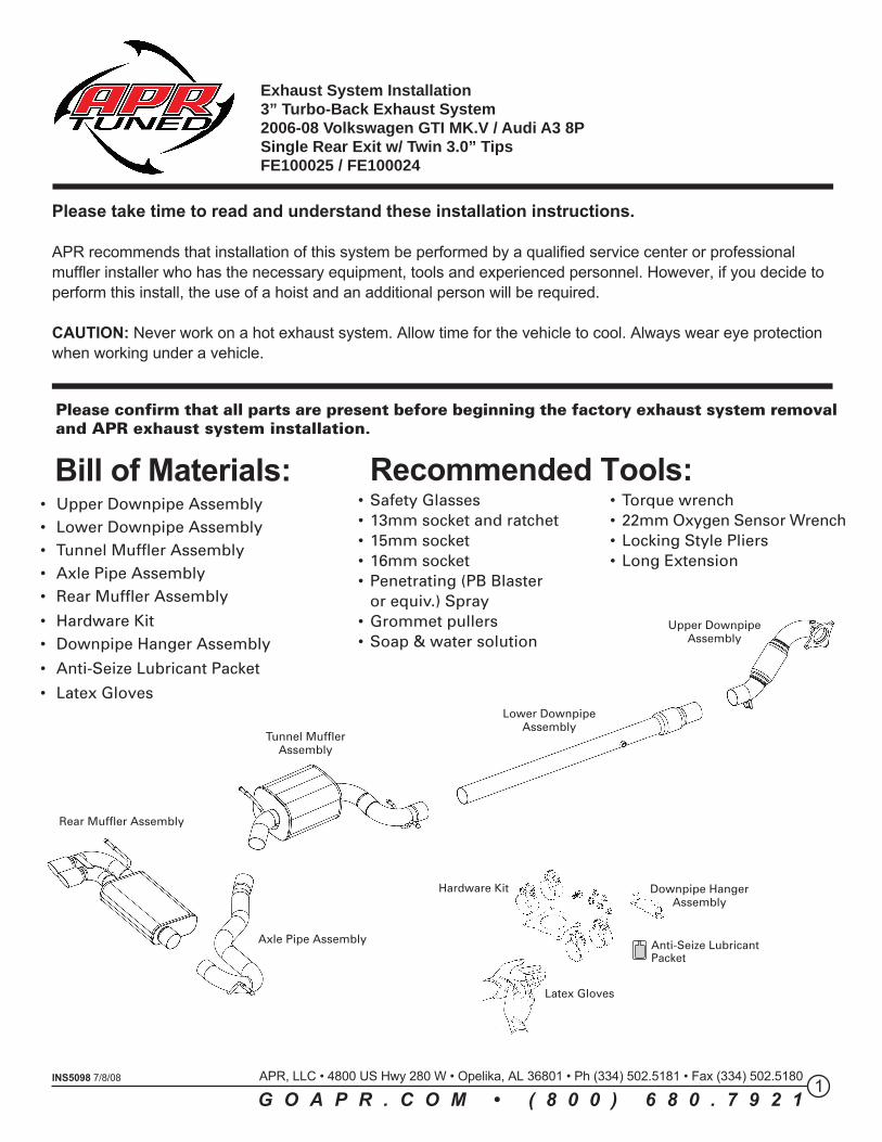
Upper DownpipeAssembly
Lower DownpipeAssembly
Tunnel MufflerAssembly
Axle Pipe Assembly
Rear Muffler Assembly
Please confirm that all parts are present before beginning the factory exhaust system removaland APR exhaust system installation.
1INS5098 7/8/08
Please take time to read and understand these installation instructions.
APR recommends that installation of this system be performed by a qualified service center or professionalmuffler installer who has the necessary equipment, tools and experienced personnel. However, if you decide toperform this install, the use of a hoist and an additional person will be required.
CAUTION: Never work on a hot exhaust system. Allow time for the vehicle to cool. Always wear eye protectionwhen working under a vehicle.
• Safety Glasses• 13mm socket and ratchet• 15mm socket• 16mm socket• Penetrating (PB Blaster
or equiv.) Spray• Grommet pullers• Soap & water solution
• Torque wrench• 22mm Oxygen Sensor Wrench• Locking Style Pliers• Long Extension
Recommended Tools:• Upper Downpipe Assembly• Lower Downpipe Assembly• Tunnel Muffler Assembly• Axle Pipe Assembly• Rear Muffler Assembly
• Hardware Kit• Downpipe Hanger Assembly
• Anti-Seize Lubricant Packet
• Latex Gloves
Bill of Materials:
Exhaust System Installation3” Turbo-Back Exhaust System2006-08 Volkswagen GTI MK.V / Audi A3 8PSingle Rear Exit w/ Twin 3.0” TipsFE100025 / FE100024
APR, LLC • 4800 US Hwy 280 W • Opelika, AL 36801 • Ph (334) 502.5181 • Fax (334) 502.5180
G O A P R . C O M • ( 8 0 0 ) 6 8 0 . 7 9 2 1
Hardware Kit
Latex Gloves
Downpipe HangerAssembly
Anti-Seize LubricantPacket
2
FIG. D
FIG. C
FIG. B
FIG. A
FIG. E
INS5098 7/8/08 APR, LLC • 4800 US Hwy 280 W • Opelika, AL 36801 • Ph (334) 502.5181 • Fax (334) 502.5180
G O A P R . C O M • ( 8 0 0 ) 6 8 0 . 7 9 2 1
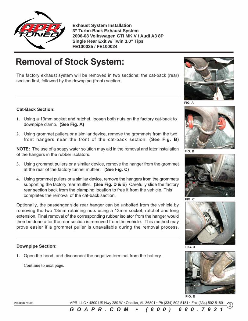
The factory exhaust system will be removed in two sections: the cat-back (rear)section first, followed by the downpipe (front) section.
Cat-Back Section:
1. Using a 13mm socket and ratchet, loosen both nuts on the factory cat-back to downpipe clamp. (See Fig. A)
2. Using grommet pullers or a similar device, remove the grommets from the two front hangers near the front of the cat-back section. (See Fig. B)
NOTE: The use of a soapy water solution may aid in the removal and later installationof the hangers in the rubber isolators.
3. Using grommet pullers or a similar device, remove the hanger from the grommetat the rear of the factory tunnel muffler. (See Fig. C)
4. Using grommet pullers or a similar device, remove the hangers from the grommetssupporting the factory rear muffler. (See Fig. D & E) Carefully slide the factoryrear section back from the clamping location to free it from the vehicle. This completes the removal of the cat-back section.
Optionally, the passenger side rear hanger can be unbolted from the vehicle byremoving the two 13mm retaining nuts using a 13mm socket, ratchet and longextension. Final removal of the corresponding rubber isolator from the hanger wouldthen be done after the rear section is removed from the vehicle. This method mayprove easier if a grommet puller is unavailable during the removal process.
Downpipe Section:
1. Open the hood, and disconnect the negative terminal from the battery.
Continue to next page.
Removal of Stock System:
Exhaust System Installation3” Turbo-Back Exhaust System2006-08 Volkswagen GTI MK.V / Audi A3 8PSingle Rear Exit w/ Twin 3.0” TipsFE100025 / FE100024
3INS5098 7/8/08 APR, LLC • 4800 US Hwy 280 W • Opelika, AL 36801 • Ph (334) 502.5181 • Fax (334) 502.5180
G O A P R . C O M • ( 8 0 0 ) 6 8 0 . 7 9 2 1
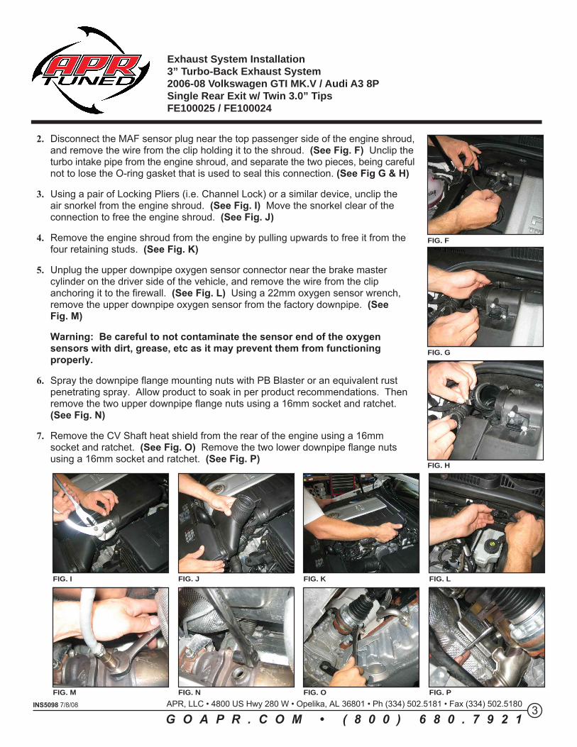
2. Disconnect the MAF sensor plug near the top passenger side of the engine shroud,and remove the wire from the clip holding it to the shroud. (See Fig. F) Unclip theturbo intake pipe from the engine shroud, and separate the two pieces, being carefulnot to lose the O-ring gasket that is used to seal this connection. (See Fig G & H)
3. Using a pair of Locking Pliers (i.e. Channel Lock) or a similar device, unclip the air snorkel from the engine shroud. (See Fig. I) Move the snorkel clear of the connection to free the engine shroud. (See Fig. J)
4. Remove the engine shroud from the engine by pulling upwards to free it from the four retaining studs. (See Fig. K)
5. Unplug the upper downpipe oxygen sensor connector near the brake master cylinder on the driver side of the vehicle, and remove the wire from the clip anchoring it to the firewall. (See Fig. L) Using a 22mm oxygen sensor wrench, remove the upper downpipe oxygen sensor from the factory downpipe. (See Fig. M)
Warning: Be careful to not contaminate the sensor end of the oxygen sensors with dirt, grease, etc as it may prevent them from functioning properly.
6. Spray the downpipe flange mounting nuts with PB Blaster or an equivalent rust penetrating spray. Allow product to soak in per product recommendations. Then remove the two upper downpipe flange nuts using a 16mm socket and ratchet. (See Fig. N)
7. Remove the CV Shaft heat shield from the rear of the engine using a 16mm socket and ratchet. (See Fig. O) Remove the two lower downpipe flange nuts using a 16mm socket and ratchet. (See Fig. P)
FIG. F
FIG. G
FIG. H
FIG. I FIG. J FIG. K FIG. L
FIG. M FIG. N FIG. O FIG. P
Exhaust System Installation3” Turbo-Back Exhaust System2006-08 Volkswagen GTI MK.V / Audi A3 8PSingle Rear Exit w/ Twin 3.0” TipsFE100025 / FE100024
Installation of APR Exhaust System:NOTE: Apply the anti-seize lubricant (supplied) to the threads ONLY of all the clampsand flange bolts. Failure to follow this procedure can cause nuts to seize on clamps andpotentially destroy threads. After applying anti-seize lubricant, be sure to thoroughlyclean hands as lubricant will tarnish stainless steel.
4INS5098 7/8/08 APR, LLC • 4800 US Hwy 280 W • Opelika, AL 36801 • Ph (334) 502.5181 • Fax (334) 502.5180
G O A P R . C O M • ( 8 0 0 ) 6 8 0 . 7 9 2 1
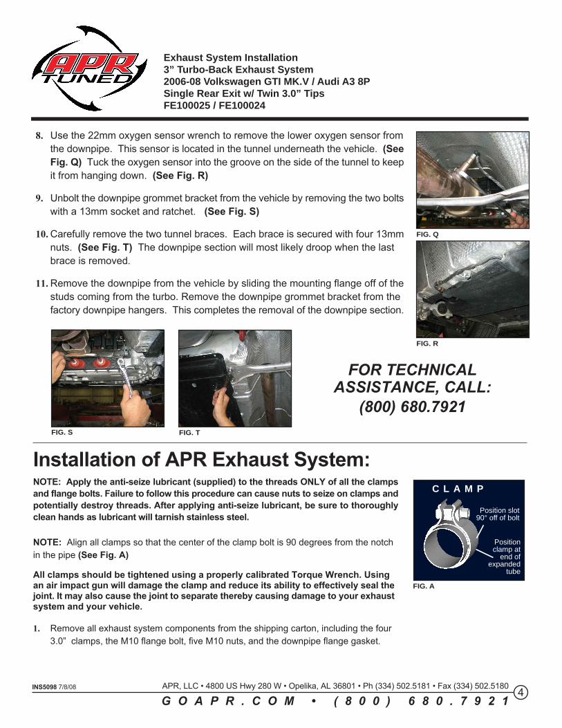
8. Use the 22mm oxygen sensor wrench to remove the lower oxygen sensor fromthe downpipe. This sensor is located in the tunnel underneath the vehicle. (SeeFig. Q) Tuck the oxygen sensor into the groove on the side of the tunnel to keepit from hanging down. (See Fig. R)
9. Unbolt the downpipe grommet bracket from the vehicle by removing the two boltswith a 13mm socket and ratchet. (See Fig. S)
10. Carefully remove the two tunnel braces. Each brace is secured with four 13mmnuts. (See Fig. T) The downpipe section will most likely droop when the last brace is removed.
11. Remove the downpipe from the vehicle by sliding the mounting flange off of thestuds coming from the turbo. Remove the downpipe grommet bracket from the factory downpipe hangers. This completes the removal of the downpipe section.
FIG. Q
FIG. R
FIG. S FIG. T
FOR TECHNICALASSISTANCE, CALL:
(800) 680.7921
NOTE: Align all clamps so that the center of the clamp bolt is 90 degrees from the notchin the pipe (See Fig. A)
All clamps should be tightened using a properly calibrated Torque Wrench. Usingan air impact gun will damage the clamp and reduce its ability to effectively seal thejoint. It may also cause the joint to separate thereby causing damage to your exhaustsystem and your vehicle.
1. Remove all exhaust system components from the shipping carton, including the four 3.0” clamps, the M10 flange bolt, five M10 nuts, and the downpipe flange gasket.
C L A M P
Position slot90° off of bolt
Positionclamp at
end ofexpanded
tube
FIG. A
Exhaust System Installation3” Turbo-Back Exhaust System2006-08 Volkswagen GTI MK.V / Audi A3 8PSingle Rear Exit w/ Twin 3.0” TipsFE100025 / FE100024
5INS5098 7/8/08 APR, LLC • 4800 US Hwy 280 W • Opelika, AL 36801 • Ph (334) 502.5181 • Fax (334) 502.5180
G O A P R . C O M • ( 8 0 0 ) 6 8 0 . 7 9 2 1
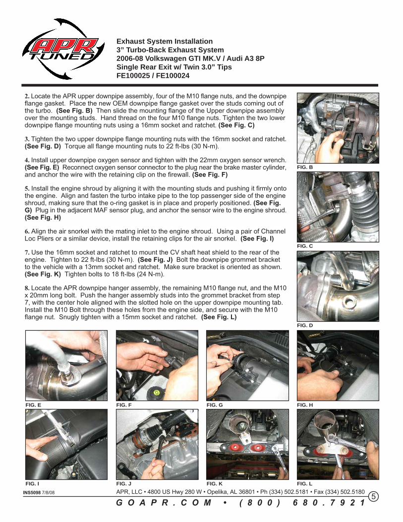
2. Locate the APR upper downpipe assembly, four of the M10 flange nuts, and the downpipeflange gasket. Place the new OEM downpipe flange gasket over the studs coming out ofthe turbo. (See Fig. B) Then slide the mounting flange of the Upper downpipe assemblyover the mounting studs. Hand thread on the four M10 flange nuts. Tighten the two lowerdownpipe flange mounting nuts using a 16mm socket and ratchet. (See Fig. C)
3. Tighten the two upper downpipe flange mounting nuts with the 16mm socket and ratchet.(See Fig. D) Torque all flange mounting nuts to 22 ft-lbs (30 N-m).
4. Install upper downpipe oxygen sensor and tighten with the 22mm oxygen sensor wrench.(See Fig. E) Reconnect oxygen sensor connector to the plug near the brake master cylinder,and anchor the wire with the retaining clip on the firewall. (See Fig. F)
5. Install the engine shroud by aligning it with the mounting studs and pushing it firmly ontothe engine. Align and fasten the turbo intake pipe to the top passenger side of the engineshroud, making sure that the o-ring gasket is in place and properly positioned. (See Fig.G) Plug in the adjacent MAF sensor plug, and anchor the sensor wire to the engine shroud.(See Fig. H)
6. Align the air snorkel with the mating inlet to the engine shroud. Using a pair of ChannelLoc Pliers or a similar device, install the retaining clips for the air snorkel. (See Fig. I)
7. Use the 16mm socket and ratchet to mount the CV shaft heat shield to the rear of theengine. Tighten to 22 ft-lbs (30 N-m). (See Fig. J) Bolt the downpipe grommet bracketto the vehicle with a 13mm socket and ratchet. Make sure bracket is oriented as shown.(See Fig. K) Tighten bolts to 18 ft-lbs (24 N-m).
8. Locate the APR downpipe hanger assembly, the remaining M10 flange nut, and the M10x 20mm long bolt. Push the hanger assembly studs into the grommet bracket from step7, with the center hole aligned with the slotted hole on the upper downpipe mounting tab.Install the M10 Bolt through these holes from the engine side, and secure with the M10flange nut. Snugly tighten with a 15mm socket and ratchet. (See Fig. L)
FIG. B
FIG. C
FIG. D
FIG. E FIG. F FIG. G FIG. H
FIG. I FIG. J FIG. K FIG. L
Exhaust System Installation3” Turbo-Back Exhaust System2006-08 Volkswagen GTI MK.V / Audi A3 8PSingle Rear Exit w/ Twin 3.0” TipsFE100025 / FE100024
6INS5098 7/8/08 APR, LLC • 4800 US Hwy 280 W • Opelika, AL 36801 • Ph (334) 502.5181 • Fax (334) 502.5180
G O A P R . C O M • ( 8 0 0 ) 6 8 0 . 7 9 2 1
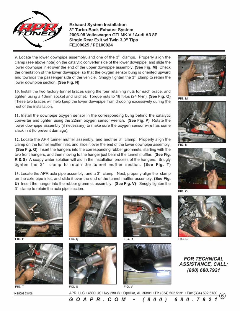
9. Locate the lower downpipe assembly, and one of the 3” clamps. Properly align theclamp (see above note) on the catalytic converter side of the lower downpipe, and slide thelower downpipe inlet over the end of the upper downpipe assembly. (See Fig. M) Checkthe orientation of the lower downpipe, so that the oxygen sensor bung is oriented upwardand towards the passenger side of the vehicle. Snugly tighten the 3” clamp to retain thelower downpipe section. (See Fig. N)
10. Install the two factory tunnel braces using the four retaining nuts for each brace, andtighten using a 13mm socket and ratchet. Torque nuts to 18 ft-lbs (24 N-m). (See Fig. O)These two braces will help keep the lower downpipe from drooping excessively during therest of the installation.
11. Install the downpipe oxygen sensor in the corresponding bung behind the catalyticconverter and tighten using the 22mm oxygen sensor wrench. (See Fig. P) Rotate thelower downpipe assembly (if necessary) to make sure the oxygen sensor wire has someslack in it (to prevent damage).
12. Locate the APR tunnel muffler assembly, and another 3” clamp. Properly align theclamp on the tunnel muffler inlet, and slide it over the end of the lower downpipe assembly. (See Fig. Q) Insert the hangers into the corresponding rubber grommets, starting with thetwo front hangers, and then moving to the hanger just behind the tunnel muffler. (See Fig.R & S) A soapy water solution will aid in the installation process of the hangers. Snuglytighten the 3” clamp to retain the tunnel muffler section . (See Fig. T)
13. Locate the APR axle pipe assembly, and a 3” clamp. Next, properly align the clampon the axle pipe inlet, and slide it over the end of the tunnel muffler assembly. (See Fig.U) Insert the hanger into the rubber grommet assembly. (See Fig. V) Snugly tighten the3” clamp to retain the axle pipe section.
FIG. M
FIG. N
FIG. O
FIG. P
FIG. T
FIG. Q
FIG. U
FIG. R
FIG. V
FIG. S
FOR TECHNICALASSISTANCE, CALL:
(800) 680.7921
Exhaust System Installation3” Turbo-Back Exhaust System2006-08 Volkswagen GTI MK.V / Audi A3 8PSingle Rear Exit w/ Twin 3.0” TipsFE100025 / FE100024
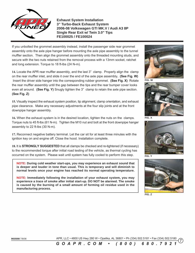
NOTE: During cold weather start-ups, you may experience an exhaust sound thatis deeper and louder in tone than usual. This is temporary and will diminish tonormal levels once your engine has reached its normal operating temperature.
NOTE: Immediately following the installation of your exhaust system, you mayexperience a trace of smoke after initial start-up. DO NOT be alarmed. The smokeis caused by the burning of a small amount of forming oil residue used in themanufacturing process.
7INS5098 7/8/08 APR, LLC • 4800 US Hwy 280 W • Opelika, AL 36801 • Ph (334) 502.5181 • Fax (334) 502.5180
G O A P R . C O M • ( 8 0 0 ) 6 8 0 . 7 9 2 1
If you unbolted the grommet assembly instead, install the passenger side rear grommetassembly onto the axle pipe hanger before mounting the axle pipe assembly to the tunnelmuffler section. Then align the grommet assembly onto the threaded mounting studs, andsecure with the two nuts retained from the removal process with a 13mm socket, ratchetand long extension. Torque to 18 ft-lbs (24 N-m).
14. Locate the APR rear muffler assembly, and the last 3” clamp. Properly align the clampon the rear muffler inlet, and slide it over the end of the axle pipe assembly. (See Fig. W) Insert the driver side hanger into the corresponding rubber grommet. (See Fig. X) Rotatethe rear muffler assembly until the gap between the tips and the rear bumper cover lookseven all around. (See Fig. Y) Snugly tighten the 3” clamp to retain the axle pipe section.(See Fig. Z)
15. Visually inspect the exhaust system position, tip alignment, clamp orientation, and exhaustpipe clearance. Make any necessary adjustments at the four slip joints and at the frontdownpipe hanger assembly.
16. When the exhaust system is in the desired location, tighten the nuts on the clamps.Torque nuts to 45 ft-lbs (61 N-m). Tighten the M10 nut and bolt at the front downpipe hangerassembly to 22 ft-lbs (30 N-m).
17. Reconnect negative battery terminal. Let the car sit for at least three minutes with theignition key on and engine off. Close the hood. Installation complete.
18. It is STRONGLY SUGGESTED that all clamps be checked and re-tightened (if necessary)to the recommended torque after initial road testing of the vehicle, as thermal cycling hasoccurred on the system. Please wait until system has fully cooled to perform this step.
FIG. W
FIG. X
FIG. Y
FIG. Z
Exhaust System Installation3” Turbo-Back Exhaust System2006-08 Volkswagen GTI MK.V / Audi A3 8PSingle Rear Exit w/ Twin 3.0” TipsFE100025 / FE100024