Embed Size (px)
DESCRIPTION
A technology overview for energy from biomass.
Citation preview

Biomass technology overview
1
Bhaskar Deol
+44 (0) 753 667 0734

Agenda
1. Biomass as a source of energy
2. Sources of biomass
3. Major conversion technologies
o Direct combustion
o Gasification
o Pyrolysis
o Anaerobic digestion
o Co-firing
o Major technologies overview
4. Bioelectricity in Europe
5. Economics of biomass
6. SWOT
7. Summary
213 June 2010 Bhaskar Deol

What is biomass
What is biomass
Biomass is a renewable organic biological material and includes materials like wood, grasses, energy crops, residues from agriculture and forestry, organic components of municipal and industrial wastes, and fumes from landfills
What is biomass energy
Biomass energy is energy produced from the direct burning of biomass, or converting it into gaseous or liquid fuels that burn more efficiently, to generate electricity or heat for industrial purposes
3
Source: EIA
13 June 2010 Bhaskar Deol

Biomass pyramid Comments
•Current total energy use is ~500 EJ/year, biomass is 10% of total energy usage
•Primary demand in 2050 is forecasted between 600-1000 EJ
•Technical potential for biomass in 2050 is 1500 EJ
•By 2050, between 250-500 EJ can be sustainably met usingbiomass• Agricultural and forestry residues~ 100 EJ
• Surplus forest production (over current harvest) ~80 EJ
• Energy crops (areas without soil degradation / water scarcity) ~120 EJ
• Energy crops (areas with soil degradation / water scarcity) ~70 EJ
• Additional potential from agricultural productivity increase ~140 EJ
Biomass as a source of energy
413 June 2010 Bhaskar Deol

Biomass to energy conversion paths
5
Heat / CHP
Electricity
Resources Conversion Products Output
Wet biomass
-Organic waste
-Manure
-Sewage, sludge
Biogas /
Landfill gas
Anaerobic
Digestion
Waste-Municipal
-Industrial
Solid biomass-Forestry residue
-Short rotational forestry
-Agricultural residue
-Energy crops
Gasification
Pyrolysis
Heat
Fuel gas
Bio oil /
biofuels
Incineration
1
2
3
4
Cofiring 5
13 June 2010 Bhaskar Deol

Direct biomass combustion
Fixed bed
• Biomass burns on a grate that travels thru the furnace, towards ash removal
• Reliable technology with low investment costs
• Limited range of biomass fuel types
Fluidized bed (bubbling / circulating)
• Fuel burns in a constantly mixing suspension of inert bed material
• Very effective mixing results in wide range of usable fuel types, if uniform particle size can be maintained
• High capex and opex is required
Dust combustion
• Small sized particles (e.g. sawdust, fine wood) is burned as a suspension in air in a combustion chamber
6
1. Solid biomass is prepared (dried, baled, chipped,
formed into pellets or briquettes)
2. Solid biomass is burned in boilers
3. Ash is removed from the system either by a grate or
as a suspension in air, depending on design
Biomass combustion schematic
Incineration
1
Fixed bed
Grate furnace
Bubbling
fluidized bed
Circulating
fluidized bed
Dust firing
13 June 2010 Bhaskar Deol

Biomass gasification
1. Biomass feedstock is converted into gaseous fuel by partial oxidation under insufficient supply of air and high temperature (~900 oC)
2. Products are H2, CO2, CH4, H20 inorganic residues & oil-tar, with calorific value ~ 10% to 50% of that of natural gas
3. This gas is burned in boilers; or after cleanup to remove tars in engines or gas turbines; or reformed to produce methanol or Hydrogen
Fixed bed gasifier
• In an updraft gasifier, air and biomass flow in counterflow, resulting in a high tar content along with the gaseous product
• In a downdraft gasifier, temperature of 1000 oC results in cracking of some of the tars and results in gas with lower tar content
Fluidized bed gasifier
• In an FB gasifier, drying, pyrolysis and gasification occurs in a fluidized mixture of inert bed material
• Various types of fluidized beds have been tested (bubbling, circulating, etc)
• These have a wide range of fuel types and can handle wet biomass but fuel needs to be treated to roughly 50mm size or smaller
• Recent developments couple fluidized beds with a combined cycle steam turbine (IGCC), which can achieve high efficiencies (~50%)
7
Gasification schematic
Gasification
2
Bubbling
fluidized bed
Circulating
fluidized bed
Updraft
fixed bed
(countercurrent)
Downdraft
Fixed bed
(cocurrent)
13 June 2010 Bhaskar Deol

Biomass pyrolysis
• Pyrolysis is very similar to gasification, but takes place at a lower temperature
• Any biomass can be considered for pyrolysis, but most work has been done on wood due to its consistency
• Biomass breaks down at 500 – 700 oC to yield partial products of char, a mixture of gases and the majority product bio-oil
• Bio-oil produced is upgraded and used in boilers, engines or gas turbines for electricity / CHP
8
Pyrolysis schematic
Pyrolysis modes and products
Pyrolysis
3
13 June 2010 Bhaskar Deol

Anaerobic digestion
• Biomass matter is fed into a tank and converted into a gas in absence of oxygen
• Solid liquid residues from the process are used as fertilizers
• Anaerobic digestion can handle very wet feedstocks, e.g. sewage sludge, agricultural and industrial organic wastes, animal by-products and organic municipal solid wastes
• Biogas contains 60-70% CH4 and remaining CO2
9
Anaerobic digestion schematic
Anaerobic
Digestion
4
13 June 2010 Bhaskar Deol

Co-firing
Direct co-firing
• Appropriately prepared biomass is fed directly into the coal furnace
• Biomass can be fed into the coal burners or dedicated biomass burners
Indirect co-firing
• Biomass is gasified (or pyrolyzed) separately to produce a fuel gas, which is burned in the coal fired furnace
• More expensive than direct co-firing and can currently only use wood fuel
Parallel co-firing
• Biomass is combusted in a separate boiler and the steam is fed into the coal fired station
• Higher temperate / pressure conditions result in increased efficiency
• Need for a parallel biomass combustion leads to higher costs
10
Indirect co-firing
Direct co-firing
Parallel co-firing
Co-firing
5
13 June 2010 Bhaskar Deol

Conversion technologies overview
11
Cofiring
Gasification
Direct
combustion
Pyrolysis
Anaerobic
Digestion
Technology Description Plant Size Comments
Fixed bed Biomass burns in a layer on a grate which moves to transport the fuel to ash removal
• Low capex• Limited range of biomass types
Fluidized bed Fuel burns in a constantly mixing suspension of hot, inert, granular bed material (e.g. silica sand)
> 20 MW • Wide range of fuels• Need uniform size• Large Capex / Opex
Dust firing Small particles (e.g. sawdust or fine wood shavings) burnedwith air in a combustion chamber
2 - 8 MW • High unit costs • Low plant efficiency
Direct co-firing Prepared biomass directly fed into the furnace 50-700 MW • Range up to 40% biomass• Typical commercial 3-5%• Typically low investment • Lowered SOx and NOx
• Indirect and parallel co-firing require increasing amounts of capital investment
Indirect-co firing Separate gasification of biomass in a fluidized bed, resulting gas is burned in the coal fired boiler furnace
15-100 MW
Parallel co-firing Biomass combusted in a separate boiler and resulting steam upgraded to that coming from the coal plant
Fixed bed Conversion of biomass to gaseous fuel by partial oxidation and elevated temperatures
Small / Decentralized
Fluidized bed (FB) Conversion of biomass to gaseous fuel in a hot, fluidized mixture with inert bed material and air. Latest developments try to combine FB with steam turbines (Integrated gasification combined cycle)
Bubbling:15-80MWCirculating:40-100MW
• FB gasifiers have high throughput and can handle various types and condition of fuel (e.g. wet biomass)
Fast pyrolysis Thermal decomposition of biomass in the absence of oxygen, resulting in char, bio-oil and combustible gases
• Pyrolysis concentrates volatile components of oil into a transportable oil
1-stage Liquid biomass is fed into a reactor where it is converted into biogas and organic material
10kW –10MW
2-stage Hydrolysis is carried out as a separate stage in AD, resulting in more stable conditions allowing higher solid content in the digester
10kW –10 MW
• Separating stages allows higher solid concentration and more stable process compared to 1-stage
13 June 2010 Bhaskar Deol

Development status of major technologies
Research & Development
Demonstration Early Commercial Commercial
Biomass Densification
TorrefactionHTU1
Pyrolysis Pelletization
Biomass to heat
Gasification Combustion(boilers and stoves)
Combustion ORC2
Stirling engine Steam cycle
Gasification IGFC3 IGCC4
IGGT5
Gasification + Steam cycle
Co-firing Indirect co-firing Parallel co-firing Direct co-firing
Anaerobic Digestion
Microbial fuel cells
Biogas upgrading
2-stage AD 1-stage AD
Biomass densification Biomass to heat Biomass to power CHP
12
1 Hydrothermal upgrading; 2 Organic rankine cycle; 3,4,5 Integrated gasification fuel cell (FC) / combined cycle (CC) / gas turbine (GT)
Source: IEA Bioenergy publication
13 June 2010 Bhaskar Deol
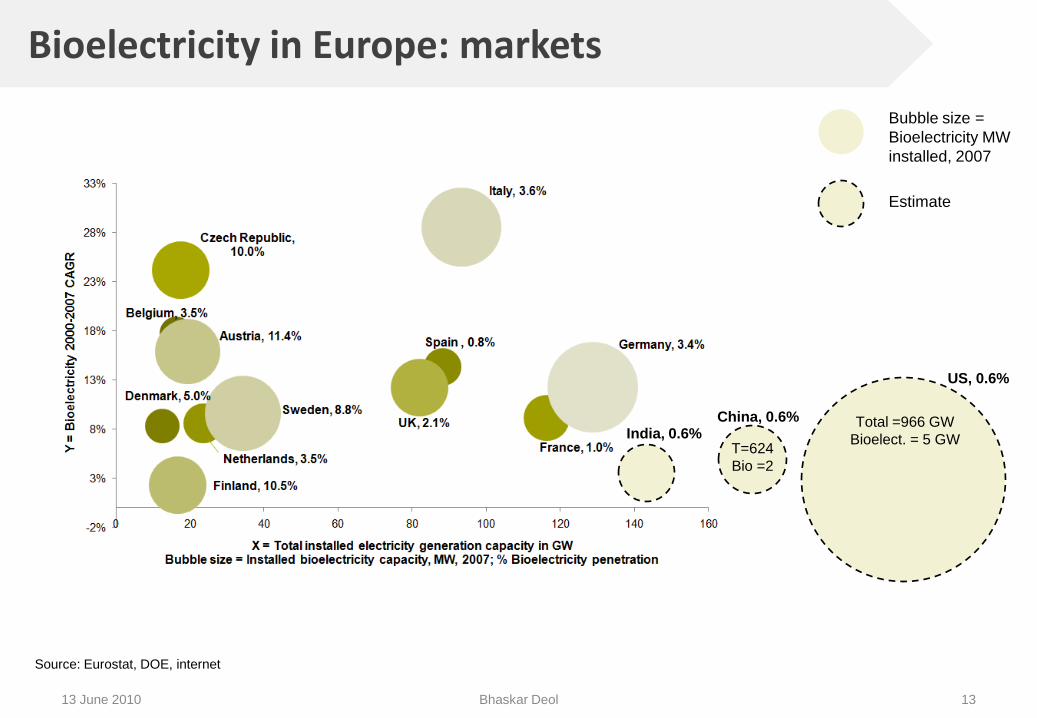
Bioelectricity in Europe: markets
13
Bubble size =
Bioelectricity MW
installed, 2007
Total =966 GW
Bioelect. = 5 GWIndia, 0.6%
US, 0.6%
Estimate
T=624
Bio =2
China, 0.6%
Source: Eurostat, DOE, internet
13 June 2010 Bhaskar Deol

Bioelectricity in Europe: sources
0
1
2
3
4
5
Belgium Denmark Spain Netherlands France Czech Republic
UK Finland Austria Sweden Italy Germany
20
07
Inst
alle
d c
apac
ity,
GW
Municipal Solid Waste
Wood/Wood Waste
Biogas
14
Source: Eurostat
13 June 2010 Bhaskar Deol
Economics of bioelectricity: capex
15
Capital cost of biomass by type
13 June 2010 Bhaskar Deol

Economics of bioelectricity: levelized
16
Levelized cost of energy $/MWh
Source: Lazard analysis
13 June 2010 Bhaskar Deol
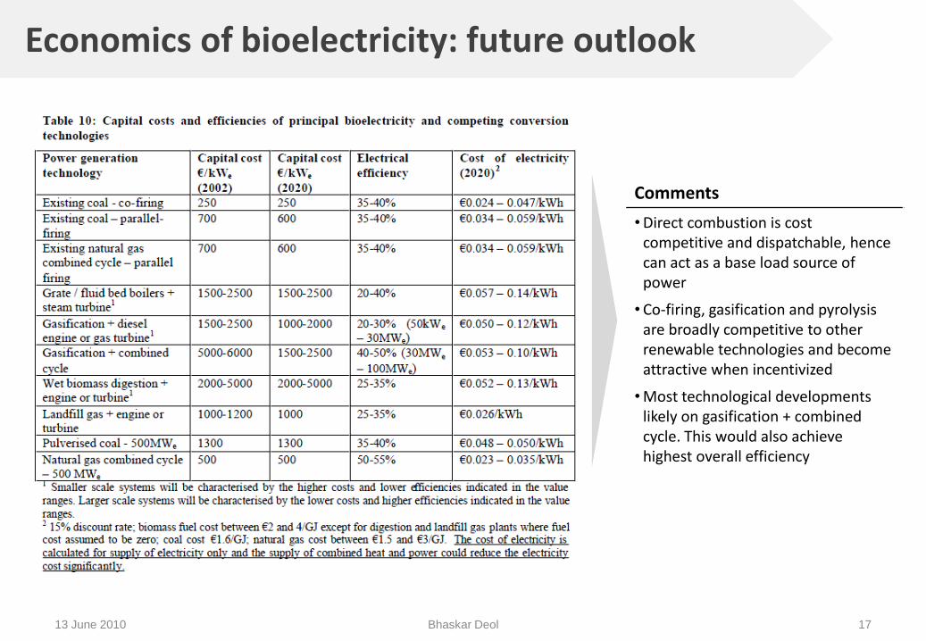
Economics of bioelectricity: future outlook
17
Comments
• Direct combustion is cost competitive and dispatchable, hence can act as a base load source of power
• Co-firing, gasification and pyrolysis are broadly competitive to other renewable technologies and become attractive when incentivized
• Most technological developments likely on gasification + combined cycle. This would also achieve highest overall efficiency
13 June 2010 Bhaskar Deol

Feed-in tariffs for biomass in Europe
Germany Biomass 2007
Germany Waste/Sewage 2007
Netherlands 2007 France 2009 UK 2009 (Proposed)
Type FIT (c€) Type FIT (c€) Type FIT (c€) Type FIT (c€) Type FIT (p)
Basic Tariff 0-150 kW 10.99 0-500 kW 7.33 Mixed 2.9Vegetable biomass
4.9Anaerobicelectricity
9
151-500 kW 9.46501 kW -5 MW
6.35 <50 MW 9.7Animalwaste
5.0Anaerobic CHP
11.5
501-5 MW 8.51
5 MW - 6.35 >50 MW 7
Biogas 9.0Biomass <50 kW
9
5-20 MW 8.03Biomass 50kW-5MW
4.5
Duration 20 years 20 years 10 years 15 years
Remarks • Special CHP Bonus• Focus on small installations• Removal of incentive for liquid biomass >150kW
• Anaerobic digestion, gasification, pyrolysis,dedicated energy crops, and biomass with CHP fall under emerging technologies category and attract 2ROC/MWh.
• 1 ROC = £ 45.52 on 10/2009
1813 June 2010 Bhaskar Deol

SWOT analysis for biomass
19
• Potentially an abundant resource
• Electricity from biomass and waste using is well
established and economically viable
• Biomass can provide baseload capacity and is
dispatchable, unlike other renewable sources
• High costs and low conversion efficiency
• Low energy density
• Fuel supply risks
• Difficulty in obtaining PPAs for small project
developers
• No market for fuels, fragmented suppliers
• Some technologies are sensitive to variety and
physical properties of feedstock
• Many biomass technologies are commercially
viable at small and large scales
• Increasing focus on bio energy would result in
increasing production of high-energy density,
purpose grown feedstock
• Favourable feed-in tariffs continue to support
small scale installations of biomass
• Financing• Perception of project complexity and risk makes
financing difficult
• Few financiers with biomass experience
• Competition from other uses of biomass, such
as biofuels, food, etc.
• Competition from other uses of land
• Public perception about emissions
• Long process for obtaining plant permissions
Strengths Weaknesses
Opportunities Threats / Barriers
13 June 2010 Bhaskar Deol

Major biomass projects
Company Name/Subsidiary Capacity Feedstock Location Status Installer Technology
Greenhunter Energy, Inc. 14MW Wood waste Florida Renovating (2009)
18.5MW Cow manure/ Wood waste California In development (2009)
Renegy Holdings 24MW Paper Mill Sludge / Wood Waste Arizona In operation
Covant a Holding Co. 1,272 MW Total -35 Plants Waste to Energy U.S./Europe In operation
76MW Total -4 Plants Wood waste/ Ag. Residues U.S. In operation 15MW Total -4 Plants Landfill Gas US In operation
Canadian Hydro Developers 25MW Wood waste Alberta In operation
Boralex Power Income Fund 63MW Wood waste Quebec Temporarily shut down
Macquarie Power & Infrastructure I.F. 28MW Wood waste Alberta In operation
31MW Wood waste Quebec In operation
Pristine Power 65MW Wood waste B.C. In development
West Fraser Timber 30MW (50% of 60MW) Wood waste B.C. In development
Run of River Power Inc. 24MW (80% of 30MW) Wood waste B.C. In development
30MW (50% of 60MW) Wood waste B.C. In development
Western Log Group / Western Bio Energy Ltd 10MW Wood Longlands Lane, Wales In operation Eco2 Wood
Fibropower Ltd 12.7MWAnimal waste (Poultry/horse/feathers)
England (Eye Airfield)
In operation Aalborg Boilers A/S
SembCorp 30MW Wood England (Wilton 10) In operation SembCorp
EPR 13.5MW Animal waste (Poultry)England (Glanford)
In operation Foster Wheeler Energy Ltd
Direct combustion, Grate
38MW StrawEngland (Ely Power Station)
In operation FLS MiljoDirect combustion, Vibrating Grate
38.5MW Animal waste (Poultry)England (Thetford)
In operation Taylor Woodrow
Direct combustion, Grate
E.on 44MW Wood (Sawmill products)Scotland (Stevens Croft)
In operation E.on
Eco2 40MW Straw England (Brigg REP) In development Eco2
40MW Straw England (Sleaford) In development Eco2
Prenergy 350MW Wood pellets Wales (Port Talbot) In development (2011) Sinclair Knight Merz
20
US
an
d C
an
ad
aU
nit
ed
Kin
gd
om
13 June 2010 Bhaskar Deol

Major biomass projects (contd.)
21
Company Name/Subsidiary Capacity Feedstock Location Status Installer Technology
Amel (operated by Renogen) 5.3MW Wood residue Belgium In operation Wartsila
BMC Moerdijk 36MW Animal waste (Poultry) Netherlands In operation Austrian energy, Siemens
Del-Nyirsegi (DBM Zrt) 20MW Wood Hungary In operation EGI Engineering
Mortagua (Enenova) 9MW Wood Portugal In operation
Pecs (Pannon Power) 65MW Wood, Natural gas Hungary In operation
Rodao (Altri SGPS SA) 11MW Wood, agricultural waste Portugal In operation
Sanguesa (EHN Group) 30MW Straw Spain In operation
Eu
rop
e
13 June 2010 Bhaskar Deol

UK 2020 renewables forecast
22
Source: DOEACC
13 June 2010 Bhaskar Deol

Summary
• Share of biomass as an energy source is going to increase over the next several years
• Multiple conversion technologies exist or are being developed efficiently utilize or to increase the viability of this abundant resource
• Biomass is one of the few renewable sources that can provide base load power and can be used on small to large scale installations
23
Technology Implications Project Implications
• Biomass is a potentially large market for cleantech
• Scope for potential investments in companies developing technology for gasification, gasification combined cycle, 2-stage anaerobic digestion and parallel co-firing
• Scope for investment in project developers or interesting business models based on biomass
• Coupled with carbon credits and FIT’s, some sources of biomass attract lucrative project returns
• Further analysis of project returns across biomass sectors needed
13 June 2010 Bhaskar Deol

Backup slides
24

Appendix 1: Energy value / Dispatchability
25
Average heat energy content of fuels Capacity factors for renewables
13 June 2010 Bhaskar Deol

Appendix 2: Integrated Gasification Combined Cycle
2613 June 2010 Bhaskar Deol

Appendix 3: Gasification products
2713 June 2010 Bhaskar Deol

Appendix 4: Detailed biomass conversion chart
2813 June 2010 Bhaskar Deol