Embed Size (px)
Citation preview

Biomechanics of smart wings in a bat robot: morphing wings using SMA actuators
This article has been downloaded from IOPscience. Please scroll down to see the full text article.
2012 Bioinspir. Biomim. 7 036006
(http://iopscience.iop.org/1748-3190/7/3/036006)
Download details:
IP Address: 138.100.76.136
The article was downloaded on 26/04/2012 at 11:59
Please note that terms and conditions apply.
View the table of contents for this issue, or go to the journal homepage for more
Home Search Collections Journals About Contact us My IOPscience
IOP PUBLISHING BIOINSPIRATION & BIOMIMETICS
Bioinspir. Biomim. 7 (2012) 036006 (16pp) doi:10.1088/1748-3182/7/3/036006
Biomechanics of smart wings in abat robot: morphing wings usingSMA actuatorsJ Colorado1, A Barrientos1, C Rossi1 and K S Breuer2
1 Centre for Automation and Robotics, Universidad Politecnica de Madrid, Madrid, Spain2 School of Engineering, Brown University, Providence, RI 02912, USA
E-mail: [email protected]
Received 7 October 2011Accepted for publication 27 February 2012Published 26 April 2012Online at stacks.iop.org/BB/7/036006
AbstractThis paper presents the design of a bat-like micro aerial vehicle with actuated morphing wings.NiTi shape memory alloys (SMAs) acting as artificial biceps and triceps muscles are used formimicking the morphing wing mechanism of the bat flight apparatus. Our objective is twofold.Firstly, we have implemented a control architecture that allows an accurate and fast SMAactuation. This control makes use of the electrical resistance measurements of SMAs to adjustmorphing wing motions. Secondly, the feasibility of using SMA actuation technology isevaluated for the application at hand. To this purpose, experiments are conducted to analyzethe control performance in terms of nominal and overloaded operation modes of the SMAs.This analysis includes: (i) inertial forces regarding the stretchable wing membrane andaerodynamic loads, and (ii) uncertainties due to impact of airflow conditions over theresistance–motion relationship of SMAs. With the proposed control, morphing actuation speedcan be increased up to 2.5 Hz, being sufficient to generate lift forces at a cruising speed of5 m s−1.
(Some figures may appear in colour only in the online journal)
1. Introduction
Bats have evolved with powerful muscles that providethe morphing capability of their wings, i.e. folding andextension of the wings during flight. To change wingmorphology, bat wings are made of flexible bones that possessindependently controllable joints [1], and a highly anisotropicwing membrane containing tiny muscles that control themembrane tension [2]. This high degree of control overthe changing shape of the wing has a great impact intothe maneuverability of the animal [3–5].
To closely mimic the morphing wing mechanism ofbats, muscle-like actuation seems to be an adequate solution.In this regard, shape memory alloys (SMAs) have openednew alternatives with the potential for building lighter andsmaller smart actuation systems [6–10]. To the best of theauthors’ knowledge, the only works attempting to reproducebio-inspired bat flight using SMAs are presented in [11] and
[12]. A robotic platform called BATMAV (fully actuated bySMA wires) is described in both papers. Thereby, SMAs havebeen used for two purposes: first, as muscle-like actuators thatprovide the flapping and morphing wingbeat motions of thebat robot, and second, as super-elastic flexible hinges that jointhe wing’s bone structure. Most of the experiments in [11]were carried out with a two degree of freedom wing capableof flapping at 3 Hz. Despite the fact that their robot is able toachieve accurate bio-inspired trajectories, the results presentedlack experimental evidence of aerodynamics measurementsthat might demonstrate the viability of their proposed design.Moreover, neither [11] nor [12] detail how to control the SMAsto achieve the bio-inspired motion of BATMAV’s wings.
The current work is oriented toward the development ofa novel biologically inspired bat aerial robot with morphingwings actuated by SMA-based artificial muscles (see figure 1).Our goal is to control these muscles to achieve morphingwing trajectories based on the biological study of bat flight
1748-3182/12/036006+16$33.00 1 © 2012 IOP Publishing Ltd Printed in the UK & the USA
Bioinspir. Biomim. 7 (2012) 036006 J Colorado et al
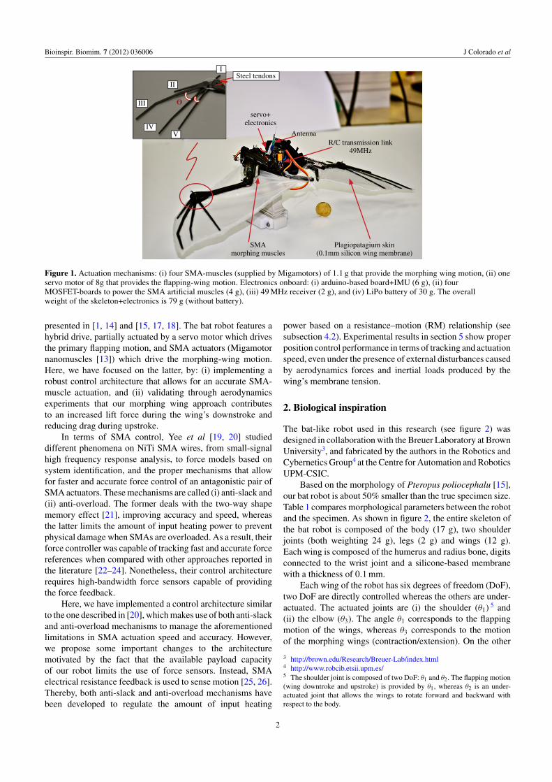
Plagiopatagium skin(0.1mm silicon wing membrane)
R/C transmission link49MHz
Antenna
Steel tendons
III
IVV
II
I
servo+electronics
SMAmorphing muscles
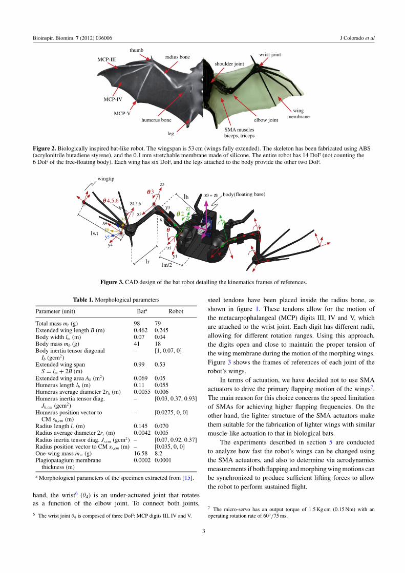
Figure 1. Actuation mechanisms: (i) four SMA-muscles (supplied by Migamotors) of 1.1 g that provide the morphing wing motion, (ii) oneservo motor of 8g that provides the flapping-wing motion. Electronics onboard: (i) arduino-based board+IMU (6 g), (ii) fourMOSFET-boards to power the SMA artificial muscles (4 g), (iii) 49 MHz receiver (2 g), and (iv) LiPo battery of 30 g. The overallweight of the skeleton+electronics is 79 g (without battery).
presented in [1, 14] and [15, 17, 18]. The bat robot features ahybrid drive, partially actuated by a servo motor which drivesthe primary flapping motion, and SMA actuators (Migamotornanomuscles [13]) which drive the morphing-wing motion.Here, we have focused on the latter, by: (i) implementing arobust control architecture that allows for an accurate SMA-muscle actuation, and (ii) validating through aerodynamicsexperiments that our morphing wing approach contributesto an increased lift force during the wing’s downstroke andreducing drag during upstroke.
In terms of SMA control, Yee et al [19, 20] studieddifferent phenomena on NiTi SMA wires, from small-signalhigh frequency response analysis, to force models based onsystem identification, and the proper mechanisms that allowfor faster and accurate force control of an antagonistic pair ofSMA actuators. These mechanisms are called (i) anti-slack and(ii) anti-overload. The former deals with the two-way shapememory effect [21], improving accuracy and speed, whereasthe latter limits the amount of input heating power to preventphysical damage when SMAs are overloaded. As a result, theirforce controller was capable of tracking fast and accurate forcereferences when compared with other approaches reported inthe literature [22–24]. Nonetheless, their control architecturerequires high-bandwidth force sensors capable of providingthe force feedback.
Here, we have implemented a control architecture similarto the one described in [20], which makes use of both anti-slackand anti-overload mechanisms to manage the aforementionedlimitations in SMA actuation speed and accuracy. However,we propose some important changes to the architecturemotivated by the fact that the available payload capacityof our robot limits the use of force sensors. Instead, SMAelectrical resistance feedback is used to sense motion [25, 26].Thereby, both anti-slack and anti-overload mechanisms havebeen developed to regulate the amount of input heating
power based on a resistance–motion (RM) relationship (seesubsection 4.2). Experimental results in section 5 show properposition control performance in terms of tracking and actuationspeed, even under the presence of external disturbances causedby aerodynamics forces and inertial loads produced by thewing’s membrane tension.
2. Biological inspiration
The bat-like robot used in this research (see figure 2) wasdesigned in collaboration with the Breuer Laboratory at BrownUniversity3, and fabricated by the authors in the Robotics andCybernetics Group4 at the Centre for Automation and RoboticsUPM-CSIC.
Based on the morphology of Pteropus poliocephalu [15],our bat robot is about 50% smaller than the true specimen size.Table 1 compares morphological parameters between the robotand the specimen. As shown in figure 2, the entire skeleton ofthe bat robot is composed of the body (17 g), two shoulderjoints (both weighting 24 g), legs (2 g) and wings (12 g).Each wing is composed of the humerus and radius bone, digitsconnected to the wrist joint and a silicone-based membranewith a thickness of 0.1 mm.
Each wing of the robot has six degrees of freedom (DoF),two DoF are directly controlled whereas the others are under-actuated. The actuated joints are (i) the shoulder (θ1) 5 and(ii) the elbow (θ3). The angle θ1 corresponds to the flappingmotion of the wings, whereas θ3 corresponds to the motionof the morphing wings (contraction/extension). On the other
3 http://brown.edu/Research/Breuer-Lab/index.html4 http://www.robcib.etsii.upm.es/5 The shoulder joint is composed of two DoF: θ1 and θ2. The flapping motion(wing downtroke and upstroke) is provided by θ1, whereas θ2 is an under-actuated joint that allows the wings to rotate forward and backward withrespect to the body.
2
Bioinspir. Biomim. 7 (2012) 036006 J Colorado et al
humerus bone
radius bonethumb
leg
elbow joint
wrist joint
SMA musclesbiceps, triceps
shoulder joint
wing membrane
MCP-III
MCP-IV
MCP-V
Figure 2. Biologically inspired bat-like robot. The wingspan is 53 cm (wings fully extended). The skeleton has been fabricated using ABS(acrylonitrile butadiene styrene), and the 0.1 mm stretchable membrane made of silicone. The entire robot has 14 DoF (not counting the6 DoF of the free-floating body). Each wing has six DoF, and the legs attached to the body provide the other two DoF.
3lh
lrlm/2
lwt
4,5,6
2
1
body(floating base)
z1
z2
z3
z4,5,6
x4
x3x1
wingtip
y4
y1
y3
y5
y6
x6
z0 = zb
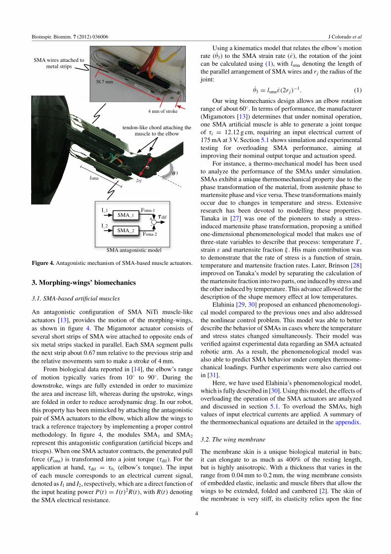
Figure 3. CAD design of the bat robot detailing the kinematics frames of references.
Table 1. Morphological parameters
Parameter (unit) Bata Robot
Total mass mt (g) 98 79Extended wing length B (m) 0.462 0.245Body width lm (m) 0.07 0.04Body mass mb (g) 41 18Body inertia tensor diagonal – [1, 0.07, 0]
Ib (gcm2)Extended wing span 0.99 0.53
S = lm + 2B (m)Extended wing area Ab (m2) 0.069 0.05Humerus length lh (m) 0.11 0.055Humerus average diameter 2rh (m) 0.0055 0.006Humerus inertia tensor diag. – [0.03, 0.37, 0.93]
Jh,cm (gcm2)Humerus position vector to – [0.0275, 0, 0]
CM sh,cm (m)Radius length lr (m) 0.145 0.070Radius average diameter 2rr (m) 0.0042 0.005Radius inertia tensor diag. Jr,cm (gcm2) – [0.07, 0.92, 0.37]Radius position vector to CM sr,cm (m) – [0.035, 0, 0]One-wing mass mw (g) 16.58 8.2Plagiopatagium membrane 0.0002 0.0001
thickness (m)
a Morphological parameters of the specimen extracted from [15].
hand, the wrist6 (θ4) is an under-actuated joint that rotatesas a function of the elbow joint. To connect both joints,
6 The wrist joint θ4 is composed of three DoF: MCP digits III, IV and V.
steel tendons have been placed inside the radius bone, asshown in figure 1. These tendons allow for the motion ofthe metacarpophalangeal (MCP) digits III, IV and V, whichare attached to the wrist joint. Each digit has different radii,allowing for different rotation ranges. Using this approach,the digits open and close to maintain the proper tension ofthe wing membrane during the motion of the morphing wings.Figure 3 shows the frames of references of each joint of therobot’s wings.
In terms of actuation, we have decided not to use SMAactuators to drive the primary flapping motion of the wings7.The main reason for this choice concerns the speed limitationof SMAs for achieving higher flapping frequencies. On theother hand, the lighter structure of the SMA actuators makethem suitable for the fabrication of lighter wings with similarmuscle-like actuation to that in biological bats.
The experiments described in section 5 are conductedto analyze how fast the robot’s wings can be changed usingthe SMA actuators, and also to determine via aerodynamicsmeasurements if both flapping and morphing wing motions canbe synchronized to produce sufficient lifting forces to allowthe robot to perform sustained flight.
7 The micro-servo has an output torque of 1.5 Kg cm (0.15 Nm) with anoperating rotation rate of 60◦/75 ms.
3
Bioinspir. Biomim. 7 (2012) 036006 J Colorado et al
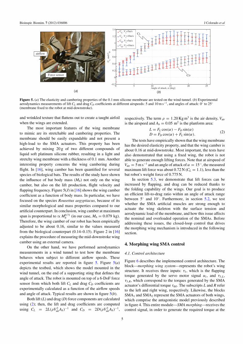
tendon-like chord attaching the muscle to the elbow
3lsma 2rj
SMA_1
SMA_2-+
I_1 Fsma-1
Fsma-2
dif
I_2
SMA antagonistic model
4 mm of stroke
38.7 mm
SMA wires attached to metal strips
Figure 4. Antagonistic mechanism of SMA-based muscle actuators.
3. Morphing-wings’ biomechanics
3.1. SMA-based artificial muscles
An antagonistic configuration of SMA NiTi muscle-likeactuators [13], provides the motion of the morphing-wings,as shown in figure 4. The Migamotor actuator consists ofseveral short strips of SMA wire attached to opposite ends ofsix metal strips stacked in parallel. Each SMA segment pullsthe next strip about 0.67 mm relative to the previous strip andthe relative movements sum to make a stroke of 4 mm.
From biological data reported in [14], the elbow’s rangeof motion typically varies from 10◦ to 90◦. During thedownstroke, wings are fully extended in order to maximizethe area and increase lift, whereas during the upstroke, wingsare folded in order to reduce aerodynamic drag. In our robot,this property has been mimicked by attaching the antagonisticpair of SMA actuators to the elbow, which allow the wings totrack a reference trajectory by implementing a proper controlmethodology. In figure 4, the modules SMA1 and SMA2
represent this antagonistic configuration (artificial biceps andtriceps). When one SMA actuator contracts, the generated pullforce (Fsma) is transformed into a joint torque (τdif). For theapplication at hand, τdif = τθ3 (elbow’s torque). The inputof each muscle corresponds to an electrical current signal,denoted as I1 and I2, respectively, which are a direct function ofthe input heating power P(t) = I(t)2R(t), with R(t) denotingthe SMA electrical resistance.
Using a kinematics model that relates the elbow’s motionrate (θ3) to the SMA strain rate (ε), the rotation of the jointcan be calculated using (1), with lsma denoting the length ofthe parallel arrangement of SMA wires and r j the radius of thejoint:
θ3 = lsmaε(2r j)−1. (1)
Our wing biomechanics design allows an elbow rotationrange of about 60◦. In terms of performance, the manufacturer(Migamotors [13]) determines that under nominal operation,one SMA artificial muscle is able to generate a joint torqueof τi = 12.12 g cm, requiring an input electrical current of175 mA at 3 V. Section 5.1 shows simulation and experimentaltesting for overloading SMA performance, aiming atimproving their nominal output torque and actuation speed.
For instance, a thermo-mechanical model has been usedto analyze the performance of the SMAs under simulation.SMAs exhibit a unique thermomechanical property due to thephase transformation of the material, from austenite phase tomartensite phase and vice versa. These transformations mainlyoccur due to changes in temperature and stress. Extensiveresearch has been devoted to modelling these properties.Tanaka in [27] was one of the pioneers to study a stress-induced martensite phase transformation, proposing a unifiedone-dimensional phenomenological model that makes use ofthree-state variables to describe that process: temperature T ,strain ε and martensite fraction ξ . His main contribution wasto demonstrate that the rate of stress is a function of strain,temperature and martensite fraction rates. Later, Brinson [28]improved on Tanaka’s model by separating the calculation ofthe martensite fraction into two parts, one induced by stress andthe other induced by temperature. This advance allowed for thedescription of the shape memory effect at low temperatures.
Elahinia [29, 30] proposed an enhanced phenomenologi-cal model compared to the previous ones and also addressedthe nonlinear control problem. This model was able to betterdescribe the behavior of SMAs in cases where the temperatureand stress states changed simultaneously. Their model wasverified against experimental data regarding an SMA actuatedrobotic arm. As a result, the phenomenological model wasalso able to predict SMA behavior under complex thermome-chanical loadings. Further experiments were also carried outin [31].
Here, we have used Elahinia’s phenomenological model,which is fully described in [30]. Using this model, the effects ofoverloading the operation of the SMA actuators are analyzedand discussed in section 5.1. To overload the SMAs, highvalues of input electrical currents are applied. A summary ofthe thermomechanical equations are detailed in the appendix.
3.2. The wing membrane
The membrane skin is a unique biological material in bats;it can elongate to as much as 400% of the resting length,but is highly anisotropic. With a thickness that varies in therange from 0.04 mm to 0.2 mm, the wing membrane consistsof embedded elastic, inelastic and muscle fibers that allow thewings to be extended, folded and cambered [2]. The skin ofthe membrane is very stiff, its elasticity relies upon the fine
4
Bioinspir. Biomim. 7 (2012) 036006 J Colorado et al
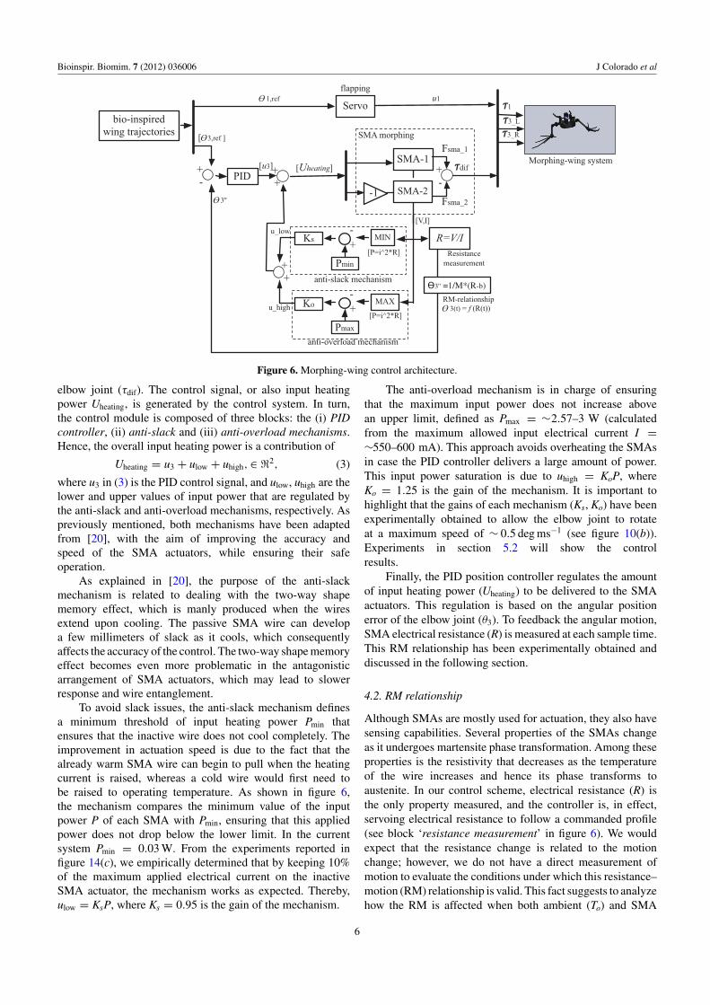
(a) (b)
CL
CDForce sensor
airflow
FL
FD
Figure 5. (a) The elasticity and cambering properties of the 0.1 mm silicone membrane are tested on the wind tunnel. (b) Experimentalaerodynamics measurements of lift CL and drag CD coefficients at different airspeeds: 5 and 10 m s−1, and angles of attack: 0◦ to 25◦
(membrane fixed to the robot at mid-downstroke).
and wrinkled texture that flattens out to create a taught airfoilwhen the wings are extended.
The most important features of the wing membraneto mimic are its stretchable and cambering properties. Themembrane should be easily expandable and not present ahigh-load to the SMA actuators. This property has beenachieved by mixing 20 g of two different compounds ofliquid soft platinum silicone rubber, resulting in a light andstretchy wing membrane with a thickness of 0.1 mm. Anotherinteresting property concerns the wing cambering duringflight. In [16], wing camber has been quantified for severalspecies of biological bats. The results of the study have shownthe influence of bat body mass (Mb) not only on the wingcamber, but also on the lift production, flight velocity andflapping frequency. Figure 5(J) in [16] shows the wing cambercoefficient as a function of body mass. In particular, we havefocused on the species Rousettus aegyptiacus, because of itssimilar morphological and mass properties compared to ourartificial counterpart. In conclusion, wing camber at maximumspan is proportional to ∝ M0.71
b (in our case, Mb = 0.079 kg).Therefore, the wing camber of our robot has been empiricallyadjusted to be about 0.16, similar to the values measuredfrom the biological counterpart (0.14–0.15). Figure 2 in [16]explains the procedure of measuring the mid-downstroke wingcamber using an external camera.
On the other hand, we have performed aerodynamicsmeasurements in a wind tunnel to test how the membranebehaves when subject to different airflow speeds. Theseexperimental results are reported in figure 5. Figure 5(a)depicts the testbed, which shows the model mounted in thewind tunnel, on the end of a supporting sting that defines theangle of attack. The robot is mounted on top of a 6-DoF forcesensor from which both lift CL and drag CD coefficients areexperimentally calculated as a function of the airflow speedsand angle of attack. Typical results are shown in figure 5(b).
Both lift (L) and drag (D) force components are calculatedusing (2); then, the lift and drag coefficients are computedusing CL = 2L(ρV 2
airAb)−1 and CD = 2D(ρV 2
airAb)−1,
respectively. The term ρ = 1.20 Kg m3 is the air density, Vair
is the airspeed and Ab = 0.05 m2 is the planform area:
L = FL cos(α) − FD sin(α)
D = FD cos(α) + FL sin(α).(2)
The tests have empirically shown that the wing membranehas the desired elasticity property, and that the wing camber isabout 0.16 at mid-downstroke. Most important, the tests havealso demonstrated that using a fixed wing, the robot is notable to generate enough lifting forces. Note that at airspeed ofVair = 5 m s−1 and an angle of attack of α = 15 ◦, the measuredmaximum lift force was about 0.72 N (CL = 1.1), less than thebat robot’s weight force of 0.775 N.
In section 5.3, we demonstrate that lift forces can beincreased by flapping, and drag can be reduced thanks tothe folding capability of the wings. Our goal is to producean efficient lift-to-drag ratio within an angle of attack rangebetween 5◦ and 10◦. Furthermore, in section 5.2, we testwhether the SMA artificial muscles are strong enough toactuate the wing skeleton with the surface tension andaerodynamic load of the membrane, and how this issue affectsthe nominal and overloaded operation of the SMAs. Beforeaddressing these issues, the closed-loop control that drivesthe morphing wing mechanism is introduced in the followingsection.
4. Morphing wing SMA control
4.1. Control architecture
Figure 6 describes the implemented control architecture. Theblock—morphing wing system—represents the robot’s wingstructure. It receives three inputs: τ1, which is the flappingtorque generated by the servo motor signal u1, and τ3,L,τ3,R, which correspond to the torques generated by the SMAactuator’s differential torque τdif. The subscripts L and R referto the left and right wing, respectively. Likewise, the blocksSMA1 and SMA2 represent the SMA actuators of both wings,which comprise the antagonistic model previously describedin figure 4. This entire module—SMA morphing—receives thecontrol signal, in order to generate the required torque at the
5
Bioinspir. Biomim. 7 (2012) 036006 J Colorado et al
SMA-1
SMA-2-+
Fsma_1
Fsma_2
[Uheating]
-1
SMA morphing
R=V/IResistance
measurement
3(t) = f (R(t))
Servo3_L
3_R
u1
[ 3,ref ]
1,ref
-+ PID
3'' =1/M*(R-b)
MIN
-+
Pmin
Ks
anti-slack mechanism
MAX
-+
Pmax
Ko
anti-overload mechanism
++
u_high
u_low
++
[V,I]
[P=i^2*R]
[P=i^2*R]
3''
Morphing-wing system
RM-relationship
bio-inspiredwing trajectories
dif[u3]
flapping
1
Figure 6. Morphing-wing control architecture.
elbow joint (τdif). The control signal, or also input heatingpower Uheating, is generated by the control system. In turn,the control module is composed of three blocks: the (i) PIDcontroller, (ii) anti-slack and (iii) anti-overload mechanisms.Hence, the overall input heating power is a contribution of
Uheating = u3 + ulow + uhigh,∈ �2, (3)
where u3 in (3) is the PID control signal, and ulow, uhigh are thelower and upper values of input power that are regulated bythe anti-slack and anti-overload mechanisms, respectively. Aspreviously mentioned, both mechanisms have been adaptedfrom [20], with the aim of improving the accuracy andspeed of the SMA actuators, while ensuring their safeoperation.
As explained in [20], the purpose of the anti-slackmechanism is related to dealing with the two-way shapememory effect, which is manly produced when the wiresextend upon cooling. The passive SMA wire can developa few millimeters of slack as it cools, which consequentlyaffects the accuracy of the control. The two-way shape memoryeffect becomes even more problematic in the antagonisticarrangement of SMA actuators, which may lead to slowerresponse and wire entanglement.
To avoid slack issues, the anti-slack mechanism definesa minimum threshold of input heating power Pmin thatensures that the inactive wire does not cool completely. Theimprovement in actuation speed is due to the fact that thealready warm SMA wire can begin to pull when the heatingcurrent is raised, whereas a cold wire would first need tobe raised to operating temperature. As shown in figure 6,the mechanism compares the minimum value of the inputpower P of each SMA with Pmin, ensuring that this appliedpower does not drop below the lower limit. In the currentsystem Pmin = 0.03 W. From the experiments reported infigure 14(c), we empirically determined that by keeping 10%of the maximum applied electrical current on the inactiveSMA actuator, the mechanism works as expected. Thereby,ulow = KsP, where Ks = 0.95 is the gain of the mechanism.
The anti-overload mechanism is in charge of ensuringthat the maximum input power does not increase abovean upper limit, defined as Pmax = ∼2.57–3 W (calculatedfrom the maximum allowed input electrical current I =∼550–600 mA). This approach avoids overheating the SMAsin case the PID controller delivers a large amount of power.This input power saturation is due to uhigh = KoP, whereKo = 1.25 is the gain of the mechanism. It is important tohighlight that the gains of each mechanism (Ks, Ko) have beenexperimentally obtained to allow the elbow joint to rotateat a maximum speed of ∼ 0.5 deg ms−1 (see figure 10(b)).Experiments in section 5.2 will show the controlresults.
Finally, the PID position controller regulates the amountof input heating power (Uheating) to be delivered to the SMAactuators. This regulation is based on the angular positionerror of the elbow joint (θ3). To feedback the angular motion,SMA electrical resistance (R) is measured at each sample time.This RM relationship has been experimentally obtained anddiscussed in the following section.
4.2. RM relationship
Although SMAs are mostly used for actuation, they also havesensing capabilities. Several properties of the SMAs changeas it undergoes martensite phase transformation. Among theseproperties is the resistivity that decreases as the temperatureof the wire increases and hence its phase transforms toaustenite. In our control scheme, electrical resistance (R) isthe only property measured, and the controller is, in effect,servoing electrical resistance to follow a commanded profile(see block ‘resistance measurement’ in figure 6). We wouldexpect that the resistance change is related to the motionchange; however, we do not have a direct measurement ofmotion to evaluate the conditions under which this resistance–motion (RM) relationship is valid. This fact suggests to analyzehow the RM is affected when both ambient (To) and SMA
6
Bioinspir. Biomim. 7 (2012) 036006 J Colorado et al
0 10 20 30 40 50 601
2
3
4
5
6
7
8
9
R [
Ohm
s]
θ3 [deg]
RM, To=23oC
RM, To=22.83oC
RM, To=22.75oC
RM, To=22.7oC
RM, To=22.6oC
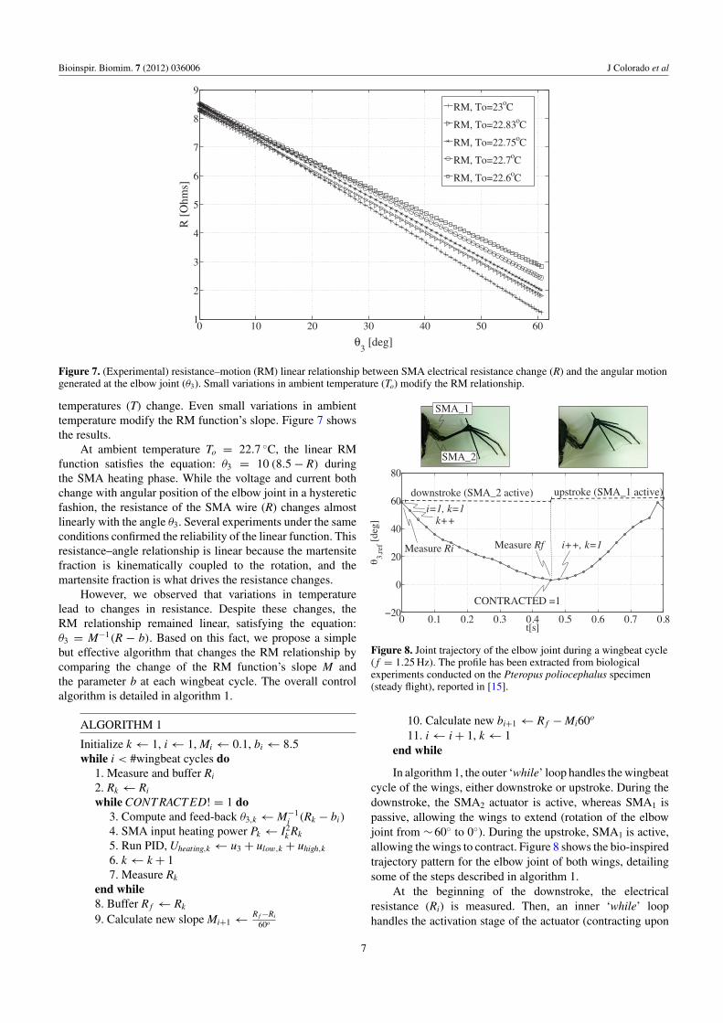
Figure 7. (Experimental) resistance–motion (RM) linear relationship between SMA electrical resistance change (R) and the angular motiongenerated at the elbow joint (θ3). Small variations in ambient temperature (To) modify the RM relationship.
temperatures (T) change. Even small variations in ambienttemperature modify the RM function’s slope. Figure 7 showsthe results.
At ambient temperature To = 22.7 ◦C, the linear RMfunction satisfies the equation: θ3 = 10 (8.5 − R) duringthe SMA heating phase. While the voltage and current bothchange with angular position of the elbow joint in a hystereticfashion, the resistance of the SMA wire (R) changes almostlinearly with the angle θ3. Several experiments under the sameconditions confirmed the reliability of the linear function. Thisresistance–angle relationship is linear because the martensitefraction is kinematically coupled to the rotation, and themartensite fraction is what drives the resistance changes.
However, we observed that variations in temperaturelead to changes in resistance. Despite these changes, theRM relationship remained linear, satisfying the equation:θ3 = M−1(R − b). Based on this fact, we propose a simplebut effective algorithm that changes the RM relationship bycomparing the change of the RM function’s slope M andthe parameter b at each wingbeat cycle. The overall controlalgorithm is detailed in algorithm 1.
ALGORITHM 1
Initialize k ← 1, i ← 1, Mi ← 0.1, bi ← 8.5while i < #wingbeat cycles do
1. Measure and buffer Ri
2. Rk ← Ri
while CONT RACT ED! = 1 do3. Compute and feed-back θ3,k ← M−1
i (Rk − bi)
4. SMA input heating power Pk ← I2k Rk
5. Run PID, Uheating,k ← u3 + ulow,k + uhigh,k
6. k ← k + 17. Measure Rk
end while8. Buffer R f ← Rk
9. Calculate new slope Mi+1 ← R f −Ri
60o
downstroke (SMA_2 active) upstroke (SMA_1 active)
i=1, k=1
i++, k=1
k++
Measure Ri
CONTRACTED =1
Measure Rf
SMA_1
SMA_2
Figure 8. Joint trajectory of the elbow joint during a wingbeat cycle( f = 1.25 Hz). The profile has been extracted from biologicalexperiments conducted on the Pteropus poliocephalus specimen(steady flight), reported in [15].
10. Calculate new bi+1 ← R f − Mi60o
11. i ← i + 1, k ← 1end while
In algorithm 1, the outer ‘while’ loop handles the wingbeatcycle of the wings, either downstroke or upstroke. During thedownstroke, the SMA2 actuator is active, whereas SMA1 ispassive, allowing the wings to extend (rotation of the elbowjoint from ∼60◦ to 0◦). During the upstroke, SMA1 is active,allowing the wings to contract. Figure 8 shows the bio-inspiredtrajectory pattern for the elbow joint of both wings, detailingsome of the steps described in algorithm 1.
At the beginning of the downstroke, the electricalresistance (Ri) is measured. Then, an inner ‘while’ loophandles the activation stage of the actuator (contracting upon
7
Bioinspir. Biomim. 7 (2012) 036006 J Colorado et al
0 0.1 0.2 0.3 0.4 0.50
7
14
21
28
35
t[s]
0 0.1 0.2 0.3 0.4
50
100
150
200
t[s]
T[d
eg]
0 20 40 600
50
100
200
0.02 0.03 0.04 0.05 0.06 0.0750
100
150
200
[
MP
a]
@350mA
@215mA
@175mA
@1A
@215mA@175mA@350mA@1A
Lower Nominal Overloaded Overheated
1
1
2
2 3
34
4
3
(d)
cooling
heating350mA
I =550mA
0
15
30
45
60
75
I =350mA
I =175mA
I =1A
3 [d
eg]
t [s]
(a)
[M
Pa]
I=350mA
I=175mA
I=550mA
I=1A
0.04 0.03 0.02 0.0150
200
heating
350mAI =350mA(b)
50454035302520
20
40
60
80
100T [C]
% A
uste
nite
20 25 30 35 40 45 5020
40
60
80
100
% M
artensite
Cooling
Heating
Ms
Af
AS
Mf
(c)
Nominal(350mA)
(a)t [s]
25 30 35 40 4520 5020
40
60
80
100
150
100
20
40
60
80
100
0.5
Figure 9. (Simulation) SMA phenomenological model response at different current profiles. (a) Joint rotation based on SMA strain.(b) Temperatures on the SMA wire. (c) Hysteresis loop for the nominal operation mode (I = 350 mA). (d) SMA strain versus stress.
heating). This loop ends when the ‘contracted’ pin of theactuator turns active, indicating that the SMA actuator isfully contracted and therefore, the joint has rotated ∼ 60◦.Inside this loop, at k = 1 (step 3 of algorithm 1), the elbowangle is calculated and fedback using the static RM function:θ3 = 10 (8.5 − R), being the function’s slope M = 0.1 andb = 8.5. This static function is shown in figure 7 (To =22.7 ◦C). Then, the SMA input heating power P is calculated instep 4, whereas the control signal (Uheating) is generated instep 5. As shown in figure 6, Uheating is calculated by thecontribution of the PID controller (u3), and both anti-slack(ulow) and anti-overload mechanisms (uhigh). This process(steps 3–7) is repeated until the end of the downstroke. Finally,when the wings are fully extended, a new function slope Mand term b are calculated based on the final measurementof electrical resistance R f (steps 8–11). Likewise, during theupstroke motion, algorithm 1 is repeated for the antagonisticSMA actuator.
5. Results
Three sets of experiments have been carried out to analyze allthe approaches introduced herein.
(i) SMA limits. Simulations and experiments are performedto explore the limits to safe overload the response of theSMA actuators, aiming at improving their nominal outputtorque and actuation speed.
(ii) Morphing wing experiments are conducted to show howthe control architecture employed (see figure 6) allows
for accurate and fast position tracking of a referencetrajectory. We have tested the overall control responseunder two conditions: (i) no-wind (Vair = 0 m s−1) and(ii) flapping at 2.5 Hz when Vair = 5 m s−1. Furthermore,we have analyzed the performance of the SMA artificialmuscles for large periods of continuous operation underwingbeat frequencies up to 2.5 Hz (fatigue issues).
(iii) Aerodynamics experiments confirm the importantbiological role that changing the wing shape enables.The morphing motion allows the bat to increase liftforces during the downstroke (wings extended), andreduce drag during the upstroke (wings folded). We haveshown that at velocities higher than Vair = 5 m s−1, ourrobot can generate enough lift forces when flapping andmorphing motions are synchronized at f = 2.5 Hz. Forlower airspeeds, the morphing motion is not synchronizedwith flapping motion; instead, the wing morphology isadjusted with the unique purpose of steering the robot,i.e. contracting/extending both wings to generate rollmomentum at the center of mass of the robot, whileflapping at f > 2.5 Hz.
5.1. SMA limits
This subsection explores the limits to safe overload theresponse of the SMA actuators. First of all, simulation testsare carried out in order to avoid physical damage of the SMAs.Subsequently, these results are contrasted against experimentaldata.
8
Bioinspir. Biomim. 7 (2012) 036006 J Colorado et al
lr
3~60º
F
Force sensor3
(a)
Connection pins
0 1 2 3 4 5 60
0.1
0.2
0.3
0.4
0.5
0.6
0.7
3
Overloaded
Nominal
(b)
0 1 2 3 4 5 6
3 [d
eg/m
s]
.
Measurements
00.1
0.2
0.3
0.4
0.5
0.6
0.7
Figure 10. (a) Wing skeleton testbed for torque measurement. (b) (Experimental) measurements of joint speed θ3 responding to stepcommands of input current I, at nominal (I = 350 mA) and overloaded (I = 550 mA) SMA operation.
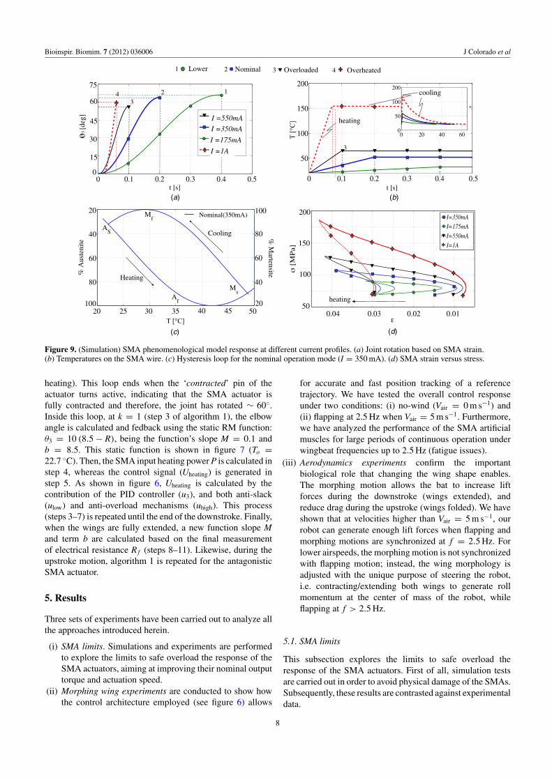
From the simulations in figure 9, one can determinethe maximum allowed input electrical current that achievesthe fastest rotation speed of the elbow joint θ3. This uppervalue can be obtained from the limits between overloadingand overheating, i.e. above the limits of the finish austenitetemperature A f . As long as the input current is smaller thana maximum allowed current, the SMAs will be safe and theangular speed resulting from this input current could be set asa feasible target speed to pursue in the experiment.
Therefore, we have tested the phenomenological modelresponse under different values of input heating current,ranging from 175 mA up to 1A. Figure 9(a) shows theangular rotation profiles (e.g. elbow joint θ3) obtained foreach input current. Figure 9(b) shows increases in the SMAwire temperature corresponding to the results shown in 9(a)(cooling temperatures are detailed in the insert). Likewise,figure 9(d) depicts the strain (ε) versus stress (σ ) curvescorresponding to the results shown in 9(b).
Regarding figure 9(a), we have used the kinematic modelin (1) to relate the strain rate of the SMA wire (ε) with themotion of the joint (θ3). Likewise, the strain was computedusing the respective equation described in the appendix. Asa first attempt, we applied an input current of 175 mA, thisbeing the value of the nominal input current suggested by themanufacturer of the SMA actuators [13]. Note that under thisvalue, the joint rotates ∼ 60◦ in 400 ms, a result too slowfor the application at hand. As expected, by increasing theinput current up to 1A, faster angular motions were achieved(up to 60◦ in 75 ms); however, the SMA finishing austenitetemperature (see figure 9(b)) was dramatically increased, beingA f = 150 ◦C, about twice as high as than the upper valuedefined in the appendix (A f = 78 ◦C). This issue clearlyillustrates an overheating problem. Overheating causes anincrease in the cooling time of the SMAs, which makes theactuator slower over a complete wingbeat cycle. It can alsocause physical damage to the shape memory effect.
In order to classify the SMA operation modes uponthe responses of input heating currents I, four modes ofSMA operation have been defined: (1) lower, (2) nominal,(3) overloaded and (4) overheated/overstressed. As observedfrom the simulations in figure 9, both nominal and overloadedmodes are feasible targets to pursue with the experiment, e.g.,by applying an input current around 550 mA, the joint is able
to rotate 60◦ in 100 ms while keeping the maximum limits oftemperature and stress below the limits of overheating.
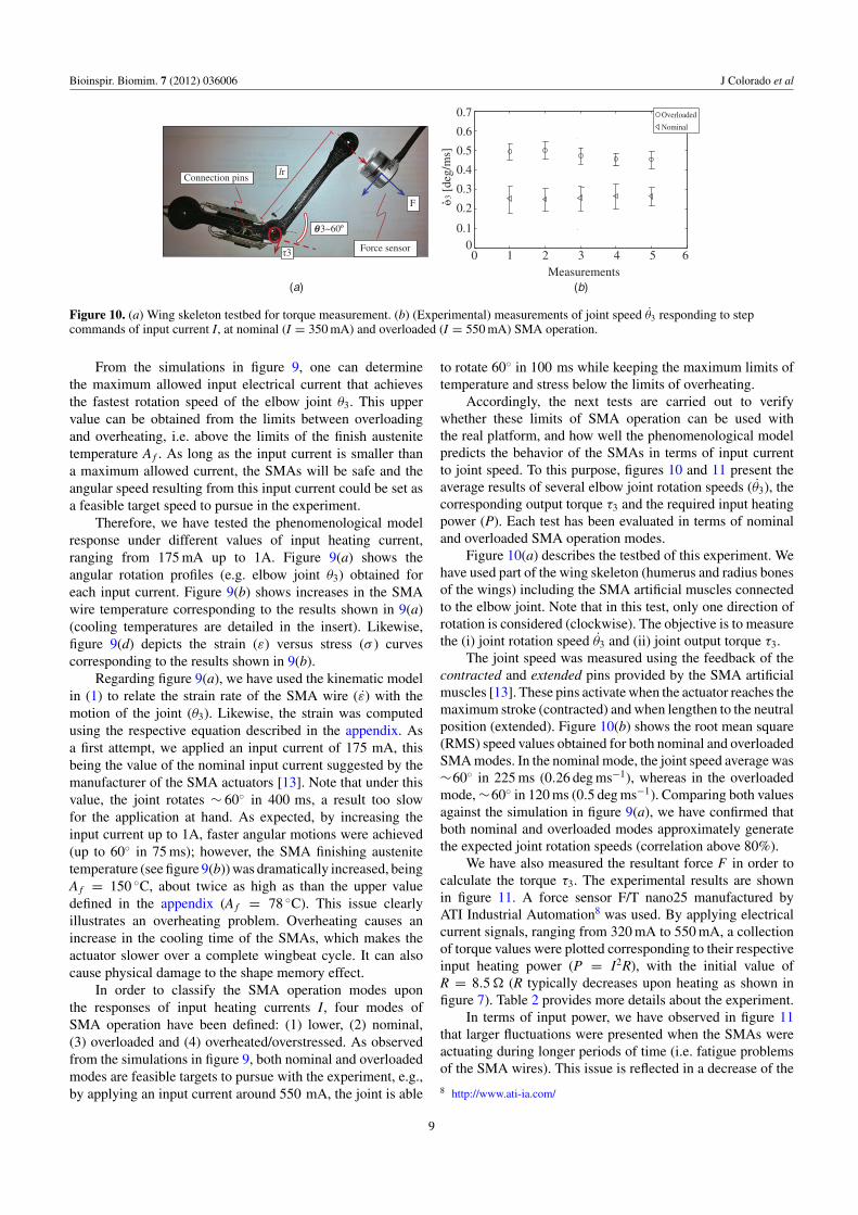
Accordingly, the next tests are carried out to verifywhether these limits of SMA operation can be used withthe real platform, and how well the phenomenological modelpredicts the behavior of the SMAs in terms of input currentto joint speed. To this purpose, figures 10 and 11 present theaverage results of several elbow joint rotation speeds (θ3), thecorresponding output torque τ3 and the required input heatingpower (P). Each test has been evaluated in terms of nominaland overloaded SMA operation modes.
Figure 10(a) describes the testbed of this experiment. Wehave used part of the wing skeleton (humerus and radius bonesof the wings) including the SMA artificial muscles connectedto the elbow joint. Note that in this test, only one direction ofrotation is considered (clockwise). The objective is to measurethe (i) joint rotation speed θ3 and (ii) joint output torque τ3.
The joint speed was measured using the feedback of thecontracted and extended pins provided by the SMA artificialmuscles [13]. These pins activate when the actuator reaches themaximum stroke (contracted) and when lengthen to the neutralposition (extended). Figure 10(b) shows the root mean square(RMS) speed values obtained for both nominal and overloadedSMA modes. In the nominal mode, the joint speed average was∼60◦ in 225 ms (0.26 deg ms−1), whereas in the overloadedmode, ∼60◦ in 120 ms (0.5 deg ms−1). Comparing both valuesagainst the simulation in figure 9(a), we have confirmed thatboth nominal and overloaded modes approximately generatethe expected joint rotation speeds (correlation above 80%).
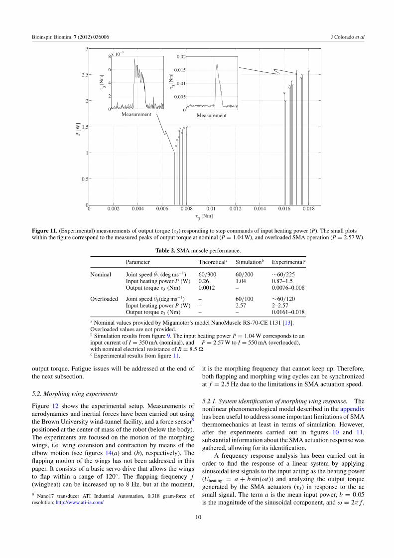
We have also measured the resultant force F in order tocalculate the torque τ3. The experimental results are shownin figure 11. A force sensor F/T nano25 manufactured byATI Industrial Automation8 was used. By applying electricalcurrent signals, ranging from 320 mA to 550 mA, a collectionof torque values were plotted corresponding to their respectiveinput heating power (P = I2R), with the initial value ofR = 8.5 (R typically decreases upon heating as shown infigure 7). Table 2 provides more details about the experiment.
In terms of input power, we have observed in figure 11that larger fluctuations were presented when the SMAs wereactuating during longer periods of time (i.e. fatigue problemsof the SMA wires). This issue is reflected in a decrease of the
8 http://www.ati-ia.com/
9
Bioinspir. Biomim. 7 (2012) 036006 J Colorado et al
0 0.002 0.004 0.006 0.008 0.01 0.012 0.014 0.016 0.0180
0.5
1
1.5
2
2.5
3
3 [Nm]
Measurement Measurement
P [W
]
Figure 11. (Experimental) measurements of output torque (τ3) responding to step commands of input heating power (P). The small plotswithin the figure correspond to the measured peaks of output torque at nominal (P = 1.04 W), and overloaded SMA operation (P = 2.57 W).
Table 2. SMA muscle performance.
Parameter Theoreticala Simulationb Experimentalc
Nominal Joint speed θ3 (deg ms−1) 60/300 60/200 ∼60/225Input heating power P (W) 0.26 1.04 0.87–1.5Output torque τ3 (Nm) 0.0012 – 0.0076–0.008
Overloaded Joint speed θ3(deg ms−1) – 60/100 ∼60/120Input heating power P (W) – 2.57 2–2.57Output torque τ3 (Nm) – – 0.0161–0.018
a Nominal values provided by Migamotor’s model NanoMuscle RS-70-CE 1131 [13].Overloaded values are not provided.b Simulation results from figure 9. The input heating power P = 1.04 W corresponds to aninput current of I = 350 mA (nominal), and P = 2.57 W to I = 550 mA (overloaded),with nominal electrical resistance of R = 8.5 .c Experimental results from figure 11.
output torque. Fatigue issues will be addressed at the end ofthe next subsection.
5.2. Morphing wing experiments
Figure 12 shows the experimental setup. Measurements ofaerodynamics and inertial forces have been carried out usingthe Brown University wind-tunnel facility, and a force sensor9
positioned at the center of mass of the robot (below the body).The experiments are focused on the motion of the morphingwings, i.e. wing extension and contraction by means of theelbow motion (see figures 14(a) and (b), respectively). Theflapping motion of the wings has not been addressed in thispaper. It consists of a basic servo drive that allows the wingsto flap within a range of 120◦. The flapping frequency f(wingbeat) can be increased up to 8 Hz, but at the moment,
9 Nano17 transducer ATI Industrial Automation, 0.318 gram-force ofresolution; http://www.ati-ia.com/
it is the morphing frequency that cannot keep up. Therefore,both flapping and morphing wing cycles can be synchronizedat f = 2.5 Hz due to the limitations in SMA actuation speed.
5.2.1. System identification of morphing wing response. Thenonlinear phenomenological model described in the appendixhas been useful to address some important limitations of SMAthermomechanics at least in terms of simulation. However,after the experiments carried out in figures 10 and 11,substantial information about the SMA actuation response wasgathered, allowing for its identification.
A frequency response analysis has been carried out inorder to find the response of a linear system by applyingsinusoidal test signals to the input acting as the heating power(Uheating = a + b sin(ωt)) and analyzing the output torquegenerated by the SMA actuators (τ3) in response to the acsmall signal. The term a is the mean input power, b = 0.05is the magnitude of the sinusoidal component, and ω = 2π f ,
10
Bioinspir. Biomim. 7 (2012) 036006 J Colorado et al
(a) (b)
(c) (d)
©Brown University©Brown University
©Brown University ©Brown University
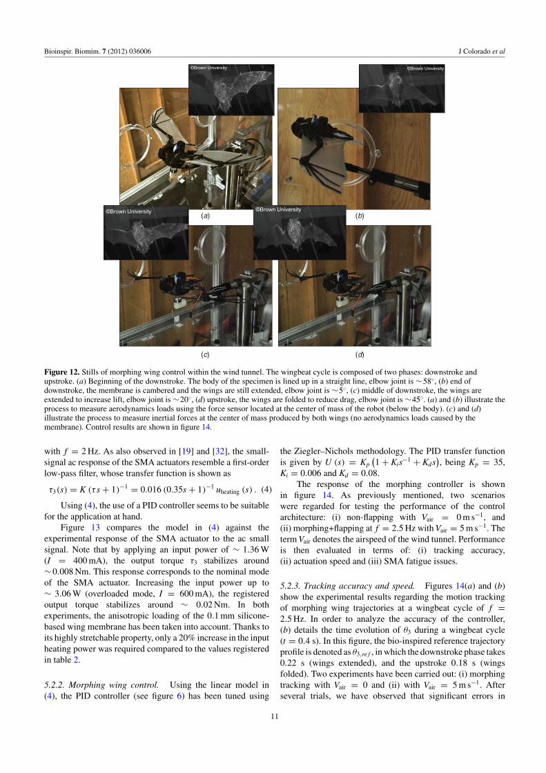
Figure 12. Stills of morphing wing control within the wind tunnel. The wingbeat cycle is composed of two phases: downstroke andupstroke. (a) Beginning of the downstroke. The body of the specimen is lined up in a straight line, elbow joint is ∼58◦, (b) end ofdownstroke, the membrane is cambered and the wings are still extended, elbow joint is ∼5◦, (c) middle of downstroke, the wings areextended to increase lift, elbow joint is ∼20◦, (d) upstroke, the wings are folded to reduce drag, elbow joint is ∼45◦. (a) and (b) illustrate theprocess to measure aerodynamics loads using the force sensor located at the center of mass of the robot (below the body). (c) and (d)illustrate the process to measure inertial forces at the center of mass produced by both wings (no aerodynamics loads caused by themembrane). Control results are shown in figure 14.
with f = 2 Hz. As also observed in [19] and [32], the small-signal ac response of the SMA actuators resemble a first-orderlow-pass filter, whose transfer function is shown as
τ3(s) = K (τ s + 1)−1 = 0.016 (0.35s + 1)−1 uheating (s) . (4)
Using (4), the use of a PID controller seems to be suitablefor the application at hand.
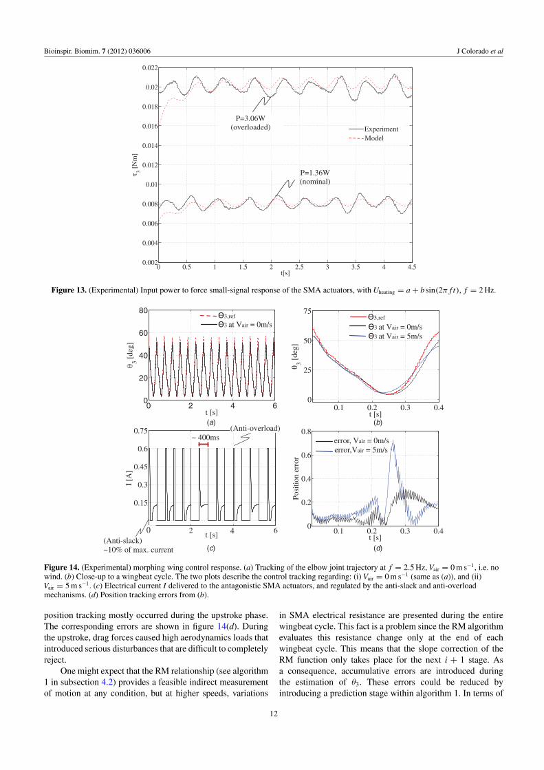
Figure 13 compares the model in (4) against theexperimental response of the SMA actuator to the ac smallsignal. Note that by applying an input power of ∼ 1.36 W(I = 400 mA), the output torque τ3 stabilizes around∼0.008 Nm. This response corresponds to the nominal modeof the SMA actuator. Increasing the input power up to∼ 3.06 W (overloaded mode, I = 600 mA), the registeredoutput torque stabilizes around ∼ 0.02 Nm. In bothexperiments, the anisotropic loading of the 0.1 mm silicone-based wing membrane has been taken into account. Thanks toits highly stretchable property, only a 20% increase in the inputheating power was required compared to the values registeredin table 2.
5.2.2. Morphing wing control. Using the linear model in(4), the PID controller (see figure 6) has been tuned using
the Ziegler–Nichols methodology. The PID transfer functionis given by U (s) = Kp
(1 + Kis−1 + Kds
), being Kp = 35,
Ki = 0.006 and Kd = 0.08.The response of the morphing controller is shown
in figure 14. As previously mentioned, two scenarioswere regarded for testing the performance of the controlarchitecture: (i) non-flapping with Vair = 0 m s−1, and(ii) morphing+flapping at f = 2.5 Hz with Vair = 5 m s−1. Theterm Vair denotes the airspeed of the wind tunnel. Performanceis then evaluated in terms of: (i) tracking accuracy,(ii) actuation speed and (iii) SMA fatigue issues.
5.2.3. Tracking accuracy and speed. Figures 14(a) and (b)show the experimental results regarding the motion trackingof morphing wing trajectories at a wingbeat cycle of f =2.5 Hz. In order to analyze the accuracy of the controller,(b) details the time evolution of θ3 during a wingbeat cycle(t = 0.4 s). In this figure, the bio-inspired reference trajectoryprofile is denoted as θ3,re f , in which the downstroke phase takes0.22 s (wings extended), and the upstroke 0.18 s (wingsfolded). Two experiments have been carried out: (i) morphingtracking with Vair = 0 and (ii) with Vair = 5 m s−1. Afterseveral trials, we have observed that significant errors in
11
Bioinspir. Biomim. 7 (2012) 036006 J Colorado et al
0 0.5 1 1.5 2 2.5 3 3.5 4 4.50.002
0.004
0.006
0.008
0.01
0.012
0.014
0.016
0.018
0.02
0.022
3 [N
m]
t[s]
P=3.06W(overloaded)
P=1.36W(nominal)
ExperimentModel
Figure 13. (Experimental) Input power to force small-signal response of the SMA actuators, with Uheating = a + b sin(2π f t), f = 2 Hz.
0 2 3 6
0.15
0.3
0.45
0.6
0.75
t [s]
I [A
]
0 2 4 60
20
40
60
80
t [s]
3 [de
g]
0.1 0.2 0.3 0.40
25
50
75
t [s]
3 [de
g]
0.1 0.2 0.3 0.40
0.2
0.4
0.6
0.8
t [s]
Posi
tion
erro
r
(Anti-slack)~10% of max. current
~ 400ms(Anti-overload)
(a) (b)
(c) (d)
3 at Vair = 0m/s3,ref 3,ref
3 at Vair = 0m/s3 at Vair = 5m/s
error, Vair = 0m/serror,Vair = 5m/s
0 4
Figure 14. (Experimental) morphing wing control response. (a) Tracking of the elbow joint trajectory at f = 2.5 Hz, Vair = 0 m s−1, i.e. nowind. (b) Close-up to a wingbeat cycle. The two plots describe the control tracking regarding: (i) Vair = 0 m s−1 (same as (a)), and (ii)Vair = 5 m s−1. (c) Electrical current I delivered to the antagonistic SMA actuators, and regulated by the anti-slack and anti-overloadmechanisms. (d) Position tracking errors from (b).
position tracking mostly occurred during the upstroke phase.The corresponding errors are shown in figure 14(d). Duringthe upstroke, drag forces caused high aerodynamics loads thatintroduced serious disturbances that are difficult to completelyreject.
One might expect that the RM relationship (see algorithm1 in subsection 4.2) provides a feasible indirect measurementof motion at any condition, but at higher speeds, variations
in SMA electrical resistance are presented during the entirewingbeat cycle. This fact is a problem since the RM algorithmevaluates this resistance change only at the end of eachwingbeat cycle. This means that the slope correction of theRM function only takes place for the next i + 1 stage. Asa consequence, accumulative errors are introduced duringthe estimation of θ3. These errors could be reduced byintroducing a prediction stage within algorithm 1. In terms of
12
Bioinspir. Biomim. 7 (2012) 036006 J Colorado et al
0
0.005
0.01
0.015
0.02
3 [N
m]
0
0.005
0.01
0.015
0
0.005
0.01
0.015
0
0.005
0.01
0 1 2 3 4
0.01
0.015
0.02
t [min]
3 [N
m]
0 4 8 12 160
0.004
0.008
0.012
0.016
t [min]
3 [N
m]
2.5Hz1.75Hz
1.35Hz
1.1Hz
1.3Hz 1.23Hz
(a) (b)
(c)
0 5
0.002
0.004
0.006
0.008
0.005
0.01
0.015
0.02
Figure 15. (Experimental) Performance of the SMA actuator for longer periods of actuation. (a) Nominal operation at 1.3 (Hz).(b) Overloaded operation at 2.5 (Hz). (c) Output torque peaks extracted from overloaded response in (b).
Table 3. Performance data of SMA actuation for longer periods oftime.
Output Actuation % PerformanceTime torque speed reductiona
Nominal initial 0.007 (Nm) 1.3 (Hz) –16 (min) 0.0068 (Nm) 1.23 (Hz) 5%initial 0.018 (Nm) 2.5 (Hz) –
Overloaded 1.5 (min) 0.015 (Nm) 1.75 (Hz) 30%3 (min) 0.011 (Nm) 1.35 (Hz) 46%5 (min) 0.008 (Nm) 1.1 (Hz) 56%
a % of reduction in the actuation speed.
actuation speed, the implemented control architecture allowedthe system to operate successfully at f = 2.5 Hz. As previouslyexplained in subsection 4.1, the adapted anti-slack and anti-overload mechanisms contributed to speed-up SMA actuation.
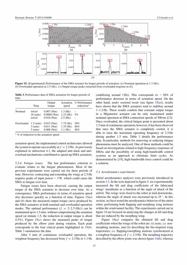
5.2.4. Fatigue issues. The last performance criterion toevaluate relates to the fatigue phenomenon. Most of theprevious experiments were carried out for short periods oftime. However, contracting and extending the wings at 2.5 Hzrequires peaks of input power ∼ 3 W, which could cause theSMA to fatigue over time.
Fatigue issues have been observed, causing the outputtorque of the SMA actuators to decrease over time. As aconsequence, SMA performance in terms of actuation speedalso decreases quickly as a function of time. Figures 15(a)and (b) show the measured output torque curve produced bythe SMA actuators at both nominal and overloaded operationmodes. The optimal performance ( f = 2–2.5 (Hz)) can bemaintained up to 1.5 min, without compromising the actuationspeed (at minute 1.5, the reduction in output torque is about4.5%). Figure 15(c) shows the measured peaks of torqueproduced by the elbow joint during rotation. Each peakcorresponds to the four critical points highlighted in 15(b).Table 3 summarizes the data.
After 5 min of continuous overloaded operation, thewingbeat frequency has decreased from f = 2.5 Hz to 1.1 Hz
(stabilizing around 1 Hz). This corresponds to ∼ 56% ofperformance decrease in terms of actuation speed. On theother hand, under nominal mode (see figure 15(a)), resultshave shown that the SMA actuators tend to stabilize around1–1.2 Hz. These results confirm that constant output torquein a Migamotor actuator can be only maintained undernominal operation at SMA contraction speeds of 300 ms [13].Once overloaded, the critical fatigue point is presented about1.5 min of continuous operation; however, it has been observedthat once the SMA actuator is completely cooled, it isable to raise the maximum operating frequency of 2.5 Hzduring another 1.5 min. Table 3 details the performancedata. In particular, methods for removing or reducing fatiguephenomena must be analyzed. One of these methods could bebased on investigations related to high-frequency responses ofSMAs and the possibility of using high-bandwidth controlsystems as an approach to eliminate limit cycles. Asdemonstrated by [19], high-bandwidth force control could bea solution.
5.3. Aerodynamics experiments
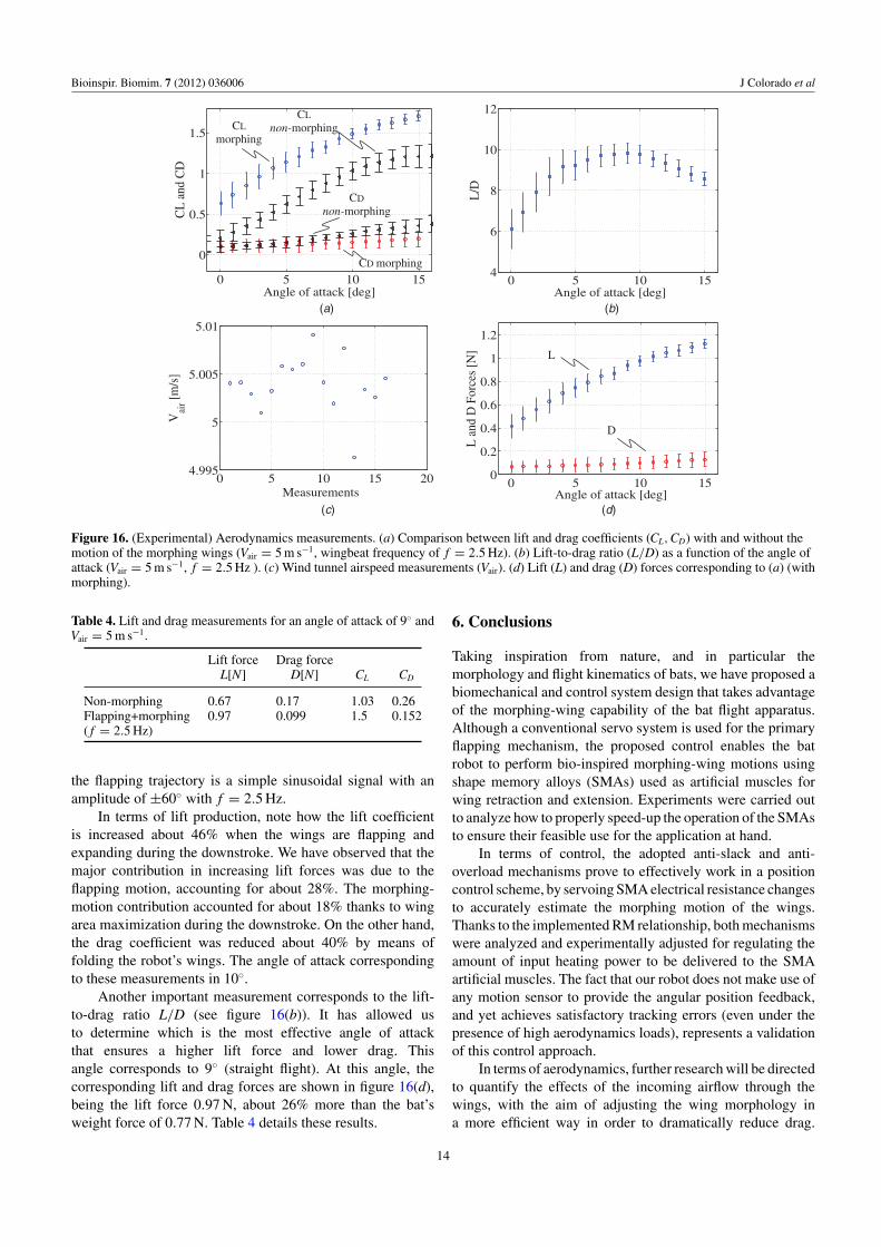
Initial aerodynamics analyses were previously introduced insection 3.2. In the tests depicted in figure 5, we experimentallymeasured the lift and drag coefficients of the fabricatedwings’ membrane as a function of the angle of attack of theairfoil. The wings were fixed to the robot at mid-downstroke,whereas the angle of attack was increased up to 25 ◦. In thissection, we have tested the aerodynamics behavior of the entirerobot, performing both flapping and morphing wing motionswithin the wind-tunnel facility. The experiments carried out infigure 16 are focused on analyzing the changes in lift and dragthat are induced by the morphing wing.
Figure 16(a) compares the obtained lift and dragcoefficients when the wings of the robot are: (i) static, i.e. non-morphing motions, and (ii) describing the bio-inspired wingtrajectories, i.e. flapping+morphing motions synchronized ata wingbeat frequency of f = 2.5 Hz. The morphing trajectorydescribed by the elbow joints was shown figure 14(b), whereas
13
Bioinspir. Biomim. 7 (2012) 036006 J Colorado et al
0 5 10 15
0
0.5
1
1.5
Angle of attack [deg]
CL
and
CD
0 5 10 154
6
8
10
12
Angle of attack [deg]
L/D
0 5 10 15 204.995
5
5.005
5.01
Measurements
Vai
r [m/s
]
0 5 10 150
0.2
0.4
0.6
0.8
1
1.2
Angle of attack [deg]
L a
nd D
For
ces
[N]
CL non-morphingCL
morphing
CD morphing
CD non-morphing
(a) (b)
(c) (d)
L
D
Figure 16. (Experimental) Aerodynamics measurements. (a) Comparison between lift and drag coefficients (CL,CD) with and without themotion of the morphing wings (Vair = 5 m s−1, wingbeat frequency of f = 2.5 Hz). (b) Lift-to-drag ratio (L/D) as a function of the angle ofattack (Vair = 5 m s−1, f = 2.5 Hz ). (c) Wind tunnel airspeed measurements (Vair). (d) Lift (L) and drag (D) forces corresponding to (a) (withmorphing).
Table 4. Lift and drag measurements for an angle of attack of 9◦ andVair = 5 m s−1.
Lift force Drag forceL[N] D[N] CL CD
Non-morphing 0.67 0.17 1.03 0.26Flapping+morphing 0.97 0.099 1.5 0.152( f = 2.5 Hz)
the flapping trajectory is a simple sinusoidal signal with anamplitude of ±60◦ with f = 2.5 Hz.
In terms of lift production, note how the lift coefficientis increased about 46% when the wings are flapping andexpanding during the downstroke. We have observed that themajor contribution in increasing lift forces was due to theflapping motion, accounting for about 28%. The morphing-motion contribution accounted for about 18% thanks to wingarea maximization during the downstroke. On the other hand,the drag coefficient was reduced about 40% by means offolding the robot’s wings. The angle of attack correspondingto these measurements in 10◦.
Another important measurement corresponds to the lift-to-drag ratio L/D (see figure 16(b)). It has allowed usto determine which is the most effective angle of attackthat ensures a higher lift force and lower drag. Thisangle corresponds to 9◦ (straight flight). At this angle, thecorresponding lift and drag forces are shown in figure 16(d),being the lift force 0.97 N, about 26% more than the bat’sweight force of 0.77 N. Table 4 details these results.
6. Conclusions
Taking inspiration from nature, and in particular themorphology and flight kinematics of bats, we have proposed abiomechanical and control system design that takes advantageof the morphing-wing capability of the bat flight apparatus.Although a conventional servo system is used for the primaryflapping mechanism, the proposed control enables the batrobot to perform bio-inspired morphing-wing motions usingshape memory alloys (SMAs) used as artificial muscles forwing retraction and extension. Experiments were carried outto analyze how to properly speed-up the operation of the SMAsto ensure their feasible use for the application at hand.
In terms of control, the adopted anti-slack and anti-overload mechanisms prove to effectively work in a positioncontrol scheme, by servoing SMA electrical resistance changesto accurately estimate the morphing motion of the wings.Thanks to the implemented RM relationship, both mechanismswere analyzed and experimentally adjusted for regulating theamount of input heating power to be delivered to the SMAartificial muscles. The fact that our robot does not make use ofany motion sensor to provide the angular position feedback,and yet achieves satisfactory tracking errors (even under thepresence of high aerodynamics loads), represents a validationof this control approach.
In terms of aerodynamics, further research will be directedto quantify the effects of the incoming airflow through thewings, with the aim of adjusting the wing morphology ina more efficient way in order to dramatically reduce drag.
14
Bioinspir. Biomim. 7 (2012) 036006 J Colorado et al
Table A1. Nonlinear SMA phenomenological model.
Variable Model Parameters Description Value (unit)
Temperature Heating: ms, R, I Mass, resistance, current 1.14 × 10⁻⁴ (kg), 8.5 ()
(T ) mscpT = I2R − hcAc (T − To) Ac Wire circumferential area 1.76 × 10⁻⁸(m2
)
Cooling: hc Heat convection coefficient 150(Jm−2 ◦C−1 s−1
)
mscpT = −hcAc (T − To) Cp Specific heat 0.2(Kcal kg−1 ◦C−1
)
Stress (σ ) Heating: Phase transformation factor −1.12 (GPa)
σ = θs−(A f −As)−1
1−(A f −As)−1
CmT θs Thermal expansion factor 0.55
(MPa
◦C−1)
Cooling: Cm,Ca Effect of stress on temperature 10.3(MPa
◦C−1)
σ = θs−(Ms−M f )−1
1−(Ms−M f )−1
CaT As, Af , Ms, Mf Temp.: austenite, martensite 68, 78, 52, 42 (◦C)
Strain (ε) Heating:ε = σ−θsT−ξ
EAEA Austenite Young mod. 75 (GPa)
Cooling: EM Martensite Young mod. 28 (GPa)
ε = σ−θsT−ξ
EM
FM (ξ ) Heating: ξm, ξa FM constants 1, 0 (dimensionless)ξ = ξm
2 [cos (aA (T − As) + bAσ ) + 1] aA Austenita amplitude factor 0.31(◦C−1
)
Cooling: aM Martensite amplitude factor 0.31(◦C−1
)
ξ = 1−ξa2
[cos
(aM
(T − Mf
) + bMσ) + 1+ξa
2
]bA, bM Stress coeff. −0.03
(◦C−1)
Actually, the wings of biological bats have tiny hairs thatsense airflow conditions, and there is some evidence that thissensing apparatus in bats contributes to their flight efficiency[33]. Besides the elbow contraction, their three DoF wristjoint also contributes to folding the digits toward the body.As a consequence, bats can reduce their wingspan about 70%during the upstroke [16]. In this work, we have attemptedto mimic part of that complexity; however, our robot is ableto reduce its wingspan about 23% during the upstroke (from0.53 m to ∼ 0.41 m). This mechanical limitation is due to thefact that the wrist joints are under-actuated, i.e. rotate as afunction of the elbow motion via steel tendons. Therefore, thewrist joint only contributes about 5% during wing contraction.Significant drag reduction still remains a challenge.
Experiments regarding fatigue issues have allowed us toverify the limits of this actuation technology. In particular,further investigations will be devoted to quantifying thelifetime of SMAs when subjected to higher stresses and largerheating currents. Methods for removing or reducing fatiguephenomenon must be analyzed. One of these methods couldbe based on investigations related to high-frequency responsesof SMAs and the possibility of using high-bandwidth controlsystems as a possible approach to eliminate limit cycles.
The developments presented in this paper are a key steptowards achieving the first bat-like robot capable of sustainedautonomous flight. The possibility of controlling the shape ofthe wings has great potential to improve the maneuverabilityof current micro aerial vehicles. Current research is devotedto the overall flight control, implementing how the bat robotcan maneuver by means of changing its wing shape, using themorphing wing control mechanism presented herein.
Acknowledgments
This work is funded by the ROBOCITY 2030-II, sponsored bythe Community of Madrid (S-0505/DPI/000235) and by the
US Air Force Office of Scientific Research. The assistanceof Rye Waldman and Joe Bahlman in the wind tunnelmeasurements is particularly appreciated.
Appendix. SMA phenomenological model
Table A1 shows the SMA phenomenological model (see[29, 30] for further details).
References
[1] Iriarte-Diaz J, Riskin D K, Willis D J, Breuer K Sand Swartz S M 2011 Whole-body kinematics of a fruit batreveal the influence of wing inertia on body accelerationsJ. Exp. Biol. 214 1546–53
[2] Swartz S M, Groves M D, Kim H D and Walsh W R 1996Mechanical properties of bat wing membrane skin J. Zool.239 357–78
[3] Swartz S M, Bishop K L and Ismael-Aguirre M-F 2005Dynamic complexity of wing form in bats: implications forflight performance Functional and Evolutionary Ecology ofBats (Oxford: Oxford University Press) pp 110–30
[4] Riskin D K, Willis D J, Iriarte-Diaz J, Hedrick T L,Kostandov M, Chen J, Laidlaw D H, Breuer K Sand Swartz S M 2008 Quantifying the complexity of batwing kinematics J. Theor. Biol. 254 604–15
[5] Lindhe-Norberg U M, Brooke A P and Trewhella W J 2000Soaring and non-soaring bats of the family Pteropodidae(flying foxes, Pteropus spp.): wing morphology and flightperformance J. Exp. Biol. 203 651–64
[6] Pons J L 2007 Emerging Actuator Technologies: AMicromechatronic Approach (New York: Wiley) pp 1–301
[7] Ouyang P, Clement R, Zhang W J and Yang G S Micro motiondevices technology: the state of arts review J. Adv. Manuf.Technol. 38 463–78
[8] Bundhoo V, Haslam E, Birch B and Park E J 2008 A shapememory alloy-based tendon-driven actuation system forbiomimetic artificial fingers, part I: design and evaluationRobotica 27 131–46
15
Bioinspir. Biomim. 7 (2012) 036006 J Colorado et al
[9] Rossi C, Coral W, Colorado J and Barrientos A 2011 Amotor-less and gear-less bio-mimetic robotic fish designICRA 2011: Proc. IEEE Int. Conf. on Robotics andAutomation (Shanghai, 9–13 May 2011) pp 3646–51
[10] Rossi C, Colorado J, Coral W and Barrientos A 2011 Bendingcontinuous structures with SMAs: a novel robotic fishdesign Bioinspir. Biomim. 6 045005
[11] Bunget G 2010 BATMAV—a bio-inspired micro-aerial vehiclefor flapping flight PhD Thesis North Carolina StateUniversity (available at https://sites.google.com/site//gheorghebunget/research/batmav)
[12] Yang S and Seelecke S 2009 FE analysis of SMA-basedbio-inspired boneÐjoint system Smart Mater. Struct.18 104020
[13] Migamotors Company, www.migamotors.com[14] Tian X, Iriarte-Diaz J, Middleton K, Galvao R, Israeli E,
Roemer A, Sullivan A, Song A, Swartz S andBreuer K 2006 Direct measurements of the kinematicsand dynamics of bat flight Bioinspir. Biomim. 1 S10–8
[15] Watts P, Mitchell E J and Swartz S M 2001 A computationalmodel for estimating the mechanics of horizontal flappingflight in bats: model description and validation J. Exp. Biol.204 2873–98
[16] Riskin D K, Iriarte-Diaz J, Middleton K M, Breuer K Sand Swartz S M 2010 The effect of body size on thewing movements of pteropodid bats, with insightsinto thrust and lift production J. Exp. Biol. 213 4110–22
[17] Alexander D A 2002 Natures Flyers: Birds, Insects and theBiomechanics of Flight (Baltimore, MD: Johns HopkinsUniversity Press)
[18] Hedenstrm A, Johansson L C, Wolf M, von Busse R, Winter Yand Spedding G R 2007 Bat flight generates complexaerodynamic tracks Science 316 894–7
[19] Yee T 2008 Fast, accurate force and position control of shapememory alloy actuators PhD Thesis Australian NationalUniversity
[20] Teh Y H and Featherstone R 2008 An architecture for fast andaccurate control of shape memory alloy actuators Int.J. Robot. Res. 27 595–611
[21] Kohl M 2004 Shape Memory Microactuators (Berlin:Springer)
[22] Grant D and Hayward V 1997 Variable structure control ofshape memory alloy actuators IEEE Syst. Control Mag.9 80–8
[23] Grant D 1999 Accurate and rapid control of shape memoryalloy actuators PhD Thesis McGill University
[24] Zhong Z W and Yeong C K 2006 Development of a gripperusing SMA wire Sensors Actuators A 126 375–38
[25] Ma N, Song G and Lee H-J 2004 Position control of shapememory alloy actuators with internal electrical resistancefeedback using neural networks Smart Mater. Struct.13 777–83
[26] Tai N T and Ahn K K 2011 Adaptive proportional–integral–derivative tuning sliding mode control for a shape memoryalloy actuator Smart Mater. Struct. 20 055010
[27] Tanaka K 1986 A thermomechanical sketch of shape memoryeffect: one-dimensional tensile behavior Res. Mech.18 251–63
[28] Brinson L C 1993 One-dimensional constitutive behaviorof shape memory alloys: thermomechanical derivationwith non-constant material functions and redefinedmartensite internal variable J. Intell. Mater. Syst. Struct.4 229–42
[29] Elahinia M H 2004 Effect of system dynamics on shapememory alloy behavior and control PhD Thesis VirginiaPolytechnic Institute and State University
[30] Elahinia M H and Ahmadian M 2005 An enhanced SMAphenomenological model: I. The shortcomings of theexisting models Smart Mater. Struct. 14 1297–308
[31] Esfahani E and Elahinia M 2007 Stable walking pattern for anSMA-actuated biped IEEE/ASME Trans. Mechatron.12 534–41
[32] Kuribayashi K 1991 Improvement of the response of an SMAactuator using a temperature sensor Int. J. Robot. Res.10 13–20
[33] Sterbing-D’Angela S, Chadha M, Chiu C, Falk B, Xian W,Barcelo J, Zook J M and Moss C F 2011 Bat wing sensorssupport flight control Proc. Natl. Acad. Sci. 108 11291–6
16