Embed Size (px)
Citation preview
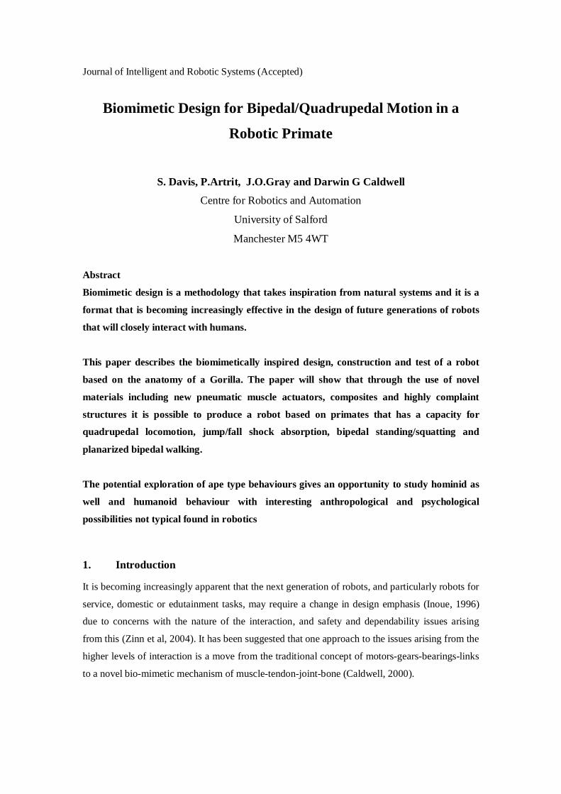
Journal of Intelligent and Robotic Systems (Accepted)
Biomimetic Design for Bipedal/Quadrupedal Motion in a
Robotic Primate
S. Davis, P.Artrit, J.O.Gray and Darwin G Caldwell
Centre for Robotics and Automation
University of Salford
Manchester M5 4WT
Abstract
Biomimetic design is a methodology that takes inspiration from natural systems and it is a
format that is becoming increasingly effective in the design of future generations of robots
that will closely interact with humans.
This paper describes the biomimetically inspired design, construction and test of a robot
based on the anatomy of a Gorilla. The paper will show that through the use of novel
materials including new pneumatic muscle actuators, composites and highly complaint
structures it is possible to produce a robot based on primates that has a capacity for
quadrupedal locomotion, jump/fall shock absorption, bipedal standing/squatting and
planarized bipedal walking.
The potential exploration of ape type behaviours gives an opportunity to study hominid as
well and humanoid behaviour with interesting anthropological and psychological
possibilities not typical found in robotics
1. Introduction
It is becoming increasingly apparent that the next generation of robots, and particularly robots for
service, domestic or edutainment tasks, may require a change in design emphasis (Inoue, 1996)
due to concerns with the nature of the interaction, and safety and dependability issues arising
from this (Zinn et al, 2004). It has been suggested that one approach to the issues arising from the
higher levels of interaction is a move from the traditional concept of motors-gears-bearings-links
to a novel bio-mimetic mechanism of muscle-tendon-joint-bone (Caldwell, 2000).

Journal of Intelligent and Robotic Systems (Accepted)
In the context of this work bio-mimetic based design is the process of taking inspiration, and
knowledge of some natural system and attempting to emulate some specific qualities or functions
to create an artificial system that has similar properties or dynamics. Although the context for bio-
mimetics can be very broad, in the work described within this paper the terminology is most
typically applied to mean a systemized and formal process of taking the properties and dynamics
from the natural world and translating them to the artificial one (Davis, 2005) .
Based on the needs of this new generation of human interactive robots and the principles of bio-
mimetic robotics, designs inspired from aspects of biological systems are becoming increasingly
important (Davis et al, 2003).
In biological entities there is no generic best body structure. Instead different creatures have
evolved differing body formats depending upon the environment in which they live, the
“lifestyle” they adopt and the strategies needed for survival. This gives rise to animals adapted to
flight, water and terrestrial living. For terrestrial creatures the mode of locomotion forms one of
the most defining requirements with leg based propulsion forming one of the pre-eminent
formats.
Within natural evolution the number of legs ranges from many tens in insects such as millipedes
to just two in humans and birds. Each leg format has certain advantages and disadvantages and
these are primarily based on the speed of locomotion, stability (both static and dynamic) and the
need for manual dexterity. This development of dexterity, although present in many creatures is
especially evident in humans with the species having evolved from walking on four legs to a two
legged biped. During this same period human’s front legs have developed digits which allow
delicate object manipulation (Leonard, 2002).
It should be noted that the dominant position of mankind in the natural order does not mean that
bipedalism is necessarily the best, and the ability to use the hands freely means that human
stability and speed are relatively poor.
However, there are species that try to combine the stability and speed of four legged locomotion
with the ability to perform delicate object manipulation. These are the primates and particularly
the great apes of which humans are, of course, members.

Journal of Intelligent and Robotic Systems (Accepted)
While humanoid development has seen extensive research in recent years (Hirai et al 1998, Hirai
1999, Chew et al 2000, Espiau et al 2000, Pfeiffer et al 2002) there have been comparatively few
attempts to replicate the form and function of apes (Nakanishi et al 1999, Kajima et al, 2004). The
aim of the work described in this chapter has the following goals:
i) Replication of the main motions of a primate (ape) although not full anatomical replication of a
primate’s mechanical structure. This will provide a platform on which to investigate quadrupedal
walking and bipedal balance, while paying attention to the dextrous capacity of the system in this
bipedal phase.
ii) Production of a bio-mimetic mechatronic structure composed of links, joints, drives and
sensors that is light, flexible, strong, energy efficient and robust. The goal is to demonstrate that
systems capable of highly complex functionality can be produced without the need for
complicated structural designs, high component counts and complexities, and precise mechanical
tolerances.
This paper will describe the analysis of the key features of a gorilla, using this data to inform the
design of a robotic version of the same animal. The primate chosen for replication was the female
gorilla and the robot produced is dimensionally similar to animal. A robot will be described that
is produced from composite materials with the majority of the skeletal structure being formed
from lightweight glass reinforced plastics and sections of high loading being formed in
aluminium and steel. This results in a 16 dof robot being produced with a mass of only 29kg. In
this paper section 2 provides an introduction to the anatomy of a gorilla. This anatomy is analysed
from a biomimetic viewpoint to provide a methodology for the design of the robotic system. The
robotic structure is described in principle in section 3 and at the component level in section 4.
Section 5 details the control architecture of the robot and testing of the performance and
robustness of the robotic primate in bipedal and quadrupedal scenarios is conducted in section 6.
In the final section conclusions relating to the robot and future work are provided.
2. Gorilla Anatomy
Before any detailed design could begin it was necessary to study basic primate anatomy and
specifically that of the gorilla. Although published literature provides basic dimensional data
regarding typical gorillas (Prue, 1976), complete skeletal structural data is illusive. It was thus
Journal of Intelligent and Robotic Systems (Accepted)
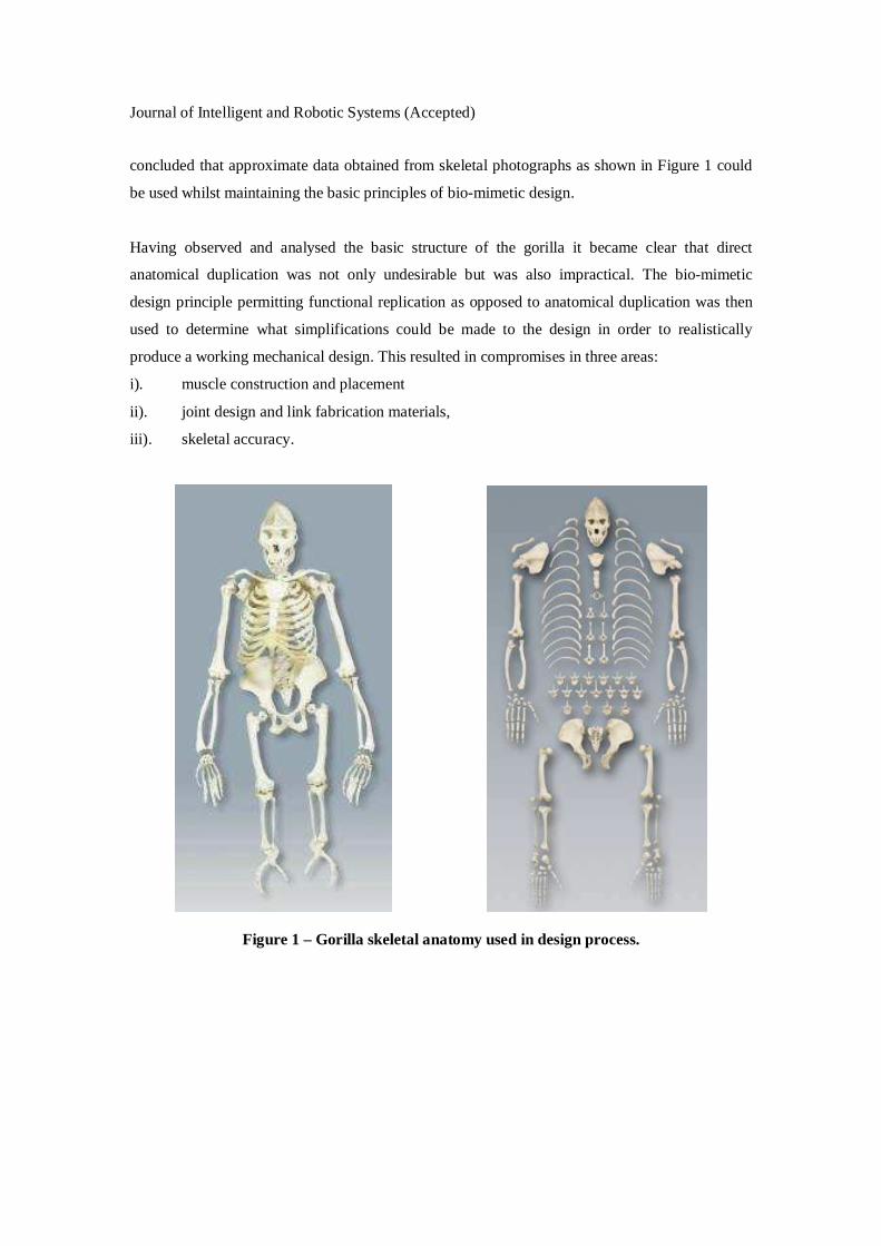
concluded that approximate data obtained from skeletal photographs as shown in Figure 1 could
be used whilst maintaining the basic principles of bio-mimetic design.
Having observed and analysed the basic structure of the gorilla it became clear that direct
anatomical duplication was not only undesirable but was also impractical. The bio-mimetic
design principle permitting functional replication as opposed to anatomical duplication was then
used to determine what simplifications could be made to the design in order to realistically
produce a working mechanical design. This resulted in compromises in three areas:
i). muscle construction and placement
ii). joint design and link fabrication materials,
iii). skeletal accuracy.
Figure 1 – Gorilla skeletal anatomy used in design process.

Journal of Intelligent and Robotic Systems (Accepted)
3. Robotic Primate Philosophy
3.1 Muscle Design and Placement
Biological muscle is a complex structure that has at the microscopic level no comparable
engineering form. However, actuation is, of course, available for robotics applications and there
has been recent development of actuators that on a macroscopic level produce functional outputs
that have good agreement with those of natural muscle. Pneumatic Muscle Actuators (pMAs)
have a particular value in this respect (Caldwell et al 1995, Chou et al 1996, Tsagarakis et 2000,
Davis et al 2003) and provide a number of characteristics that are desirable for the stated task:
i. Muscles can be produced in a range of lengths and diameters and are simple to
manufacture.
ii. Actuators have an extremely high power to weight ratio.
iii. Muscles contract by 30-35% of their dilated length, depending upon construction. This is
comparable with natural muscle.
iv. ‘Soft’ construction and finite maximum contraction make pMA safe for human-machine
interaction.
v. Muscles can be controlled to a displacement accuracy of 1% and can have a bandwidth of
5Hz when operating with an antagonist.
vi. Compared with natural muscle pMAs provide up to 10 times more force for a similar cross-
sectional area.
vii. pMAs are extremely tolerant of mechanical inaccuracies coping with both lateral and
rotational misalignment of components through the inherent compliance of the actuator.
For these reasons pneumatic Muscle Actuators were selected as the drive for the robot.
In nature the muscles used to power the limbs are varied and numerous. There appear to be two
reasons for this,
a). the joints used in nature need supporting to stop them from dislocating and many of
the muscles have a stabilising role holding the joints together.
b) using multiple muscles to power joints provides a degree of damage tolerance. Hence
if one muscle becomes damaged the body can adapt and use alternative muscles to achieve the
same task.

Journal of Intelligent and Robotic Systems (Accepted)
Each of the many muscles used to power a particular joint are coupled and so to generate a
particular motion each of the muscles needs to be activated to some extent. This high degree of
coupling is not a problem in nature, however, artificial replication of such a system presents a
substantial challenge to control engineers and it is therefore reasonable, and indeed necessary, to
simplify the design wherever possible.
3.2. Joint Design
Nature does not use the same techniques and material that are available to engineers to form
joints. This can be seen by looking at one of the simplest joints in a primate’s body, the elbow,
Figure 2 (Kapandji 1987). The joint is formed by the rotation of the rounded head of the Humerus
bone in an equally sized socket in the Ulna bone. The contact point between the two bones is
cushioned by cartilage which allows smooth motion and protects the bones from wear. Ligaments
cover the joint ensuring that it does not come apart and provided the stabilisation of the links and
the joints. Motion of the joint is produced by activation of several muscle groups working in
combination (and on occasions in opposition) of which the primary units are the biceps and
triceps. These muscles act through a simple leaver action to produce a torque at the joint.
Figure 2 – The elbow joint of a primate.
Engineering techniques provide methods of producing joints that are much better suited
mechanically and these include hinges, universal joints and flexible couplings. In light of this,
replication of a natural joint seems unnecessary and so standard engineering methods were used
in the robots design to form joints.

Journal of Intelligent and Robotic Systems (Accepted)
The primate robot uses a combination of two different joint designs, the first is a simple lever
joint, similar to that found in nature, and the second uses a belt and pulley. The lever joint is very
simple to construct, for example, one end of the muscle is attached to the tibia and the other to the
foot. As the muscle contracts so the joint rotates. However, there is a problem with this method.
As the muscle contracts and causes the joint angle to change the effective lever length (L)
becomes smaller, Figure 3. Also as the joint rotates the length of the muscle used to power it
becomes less, due to muscle contraction, and therefore the force F it produces reduces. The
combination of the lowering force and reducing effective lever length causes the torque applied to
the joint to drop off very rapidly.
L L
F
F
Beltadjustment
screw
MusclesPulley
Timingbelt
Fig 3. Joint angle dependent lever length. Fig 4 Timing belt design for consistent output.
The second method used overcomes this problem by using a pulley to maintain the lever at a
fixed length. A steel reinforced timing belt connected to the two muscles passes over the pulley as
can be seen in Fig 4. A fixing screw holds the belt on the pulley and stops it from slipping
when there is no force on the muscles. The same screw can also be used to allow the range of
motion of a joint to easily be adjusted. With the screw removed the belt can be moved relative to
the pulley and then when the desired range of motion is set the screw is replaced, this proves to be
a highly useful feature. Although pulleys are not used in nature their inclusion here can be
justified by remembering that the aim was to duplicate primate functionality but not necessarily
the way it achieves this functionality.

Journal of Intelligent and Robotic Systems (Accepted)
One highly important features of biological joints that, of course, cannot yet be replicated is the
self-repair possible in organic joints that permits the joint to renew itself throughout life and to
repair itself quickly after significant damage.
3.3. Skeletal Accuracy
The gorilla skeleton, figure 1, is formed from more than 200 structural bones, with many more
bones that do not play a central part in the motion and locomotion behaviour of the animal. Good
bio-mimetic design shows that it is unnecessary to replicate each of these bones in a robotic
system as techniques not possible in nature can be used in engineering to create similar structures
with a considerable reduction in complexity. Based on the good use of engineering design and
materials the robotic gorilla has been constructed with approximately one quarter the number of
major ‘bones’ that are used in nature. Basic functionality of the gorilla can be replicated without
the need for completely copying the mechanical structure of the gorilla as some of the functions
are very task specific and are not used in normal behaviours. This means that some of the degrees
of freedom could be neglected without hindering the overall operation.
4. Robotic Primate Mechanical Design
Having studied basic primate anatomy and identified the areas where the biomimetic design
principle could be used to reduce complexity a robotic structure was produced. The nature of the
actuators mean the robot does not need to be constructed to high tolerance specifications. The
actuators are highly flexible allowing both linear and rotational misalignments to be overcome
through slight deformation of the actuator’s body. This reduces the number of machined
components used in the design allowing more rapid and lower cost production. Whilst this less
precise design leads to some errors in control models the overall operation of the mechanical
system is unaffected yet the build process is immensely simplified. This tolerance of mechanical
imprecision is in many respects analogous with biological systems were there is no ideal structure
and all animals in a species are truly unique. It is also conceivable that in the longer term the
ability to cope with imprecision or changes in the structure of the robot will permit the possibility
of robot that can change their morphology ie grow.
4.1 Lower Limbs
Gorillas have two legs which provide both true but limited bipedal locomotion and, when used in
conjunction with the arms form part of a quadrupedal walking platform. Despite having the

Journal of Intelligent and Robotic Systems (Accepted)
ability to walk “upright” in a conventional bipedal walking mode use of this capacity is rare, and
it is usually seen in the form of a charge and seldom continues for more than a few paces. Bipedal
standing is in contrast comparatively common as it allows extended reach.
The range of motion in the lower limbs varies between species of humanoid/hominid ape, with
humans having the largest degree of flexibility. The gorilla has a reduced range and most notably
is not capable of completely straightening its legs. While adhering to the biomimetic design
principle it was decided that complete mechanical and motive duplication of the primates leg was
not necessary. Some of the degrees of freedom are only used in more complex climbing motions
and these are not currently of interest for quadrupedal and bipedal walking and standing.
Therefore the design was simplified by the inclusion of only the three joints and degrees of
freedom acting in the sagittal plane.
Analysing the actions that form the basis of the gorilla leg it is clear that the hip is the most
complex joint with three degrees of freedom, however, for quadrupedal walking and bipedal
standing only one of these actions is needed and this is the joint that provides flexion-extension.
The muscles used to actuate the hip joint are located within the centre of a pelvis with motion
being transferred to the leg through a shaft to which the femur is mounted, figure 5. Due the
nature of the pMA which provides a contractile stroke, in the same manner as organic muscle, all
pMAs are used in pairs with antagonistic actions of flexion-extension. This format permits
simultaneous control of both position and stiffness which are very beneficial features found in
biological muscle but difficult to replicate with most traditional robotic actuation. The force
produced by the muscles (200 mm long and 40 mm in diameter) is applied across a 50mm
diameter pulley which generates a maximum torque of ≈63Nm at an air pressure of 4bar
(400kPa). This provides a total output force in the two legs which can easily support the 29kg
mass of the robot when standing.
The knee has 1 dof with the muscles (260mm long and 40mm in diameter) used to actuate it
located in the upper thigh with an antagonistic pair operating across a pulley located at the point
of knee rotation, figure 5. This pulley is 60mm in diameter and generates a maximum torque of
≈ 75Nm at the knee. A gorilla is not capable of straightening its leg and by adjusting the position
of the belt on the pulley the range of motion was set to the values shown in Table 1. This
limitation means that the limb never reaches its singular configuration control becomes easier.

Journal of Intelligent and Robotic Systems (Accepted)
The robot has a simple one dof ankle which provides foot up/down (plantar/dorsi-flexion) motion.
This is achieved by muscles (260mm long and 40mm in diameter) attached directly from the foot
to the lower leg, which is in the form of a single ‘bone’ rather than duplicating the tibia and
fibula. The joint is of the lever type and produces a maximum torque of 150Nm. In nature the
tibia and fibula cross one another to create a degree of twist at the foot. In mechanical terms there
are more appropriate ways of creating this motion but ultimately it was decided that the range of
motion was so small that it would not contribute significantly to the operation of the robot. The
third motion that primates have in the ankle is inversion/eversion which is a lateral movement.
Again the range of this motion is small and it is primarily used in balanced or unassisted bipedal
walking. As this is not currently the aim of this work the degree of freedom was not included in
the design, however, this has been achieved in a previous lower limb robotic systems and can
easily be added in the future if it is necessary (Artrit et al 2001). The robot’s legs, Figure 5, are
660mm in length and the range of motion provided by each joint can be seen in Table 1.
Joint Range
Hip 30-150°
Knee 10-120°
Ankle ±30°
Table 1 – Joint ranges of robotic leg.
Figure 5 Comparison of Gorilla and Robotic Leg consisting of 3 dof.
Pelvis
Actuators
Joint

Journal of Intelligent and Robotic Systems (Accepted)
4.2 Torso and Pelvis
The main feature of the upper body of a gorilla is its spine created from numerous individual
vertebrae, attached to which are thirteen ribs which create a protective enclosure for the internal
organs. In the development of a robotic primate it was felt that direct duplication of this is not
necessary as the flexibility of the spine can be replicated, to a limited degree, by using a rigid
spine which attaches to the lower body by means of a flexible coupling.
(a) (b)
Figure 6 – Torso and pelvis front(a) and rear(b).
The single spinal column was created from 50mm Glass Reinforced Plastic composite (GRP) box
section onto which a ribcage was mounted as can be seen in Figure 6(a). This consists of three
ribs interconnected by a central sternum that forms a protective cage in which to house the robot’s
control hardware. This is not anatomically accurate, as the robot has now effectively had its brain
embedded in the chest cavity, however, the protective nature of the rib cage emulates the safety
provided by the skull and the introduction of the computation systems in this area provides a
better and more natural distribution of mass. Also the robot has no need for a cardiopulmonary
system, although valves used to control the activation of the muscles could be considered
analogous to a cardiovascular system. Additional protection is given to the most delicate parts of
the control system by a polyurethane enclosure which was also mounted to the spinal column
with a ‘quick release’ system allowing ease of removal for maintenance and upgrade.

Journal of Intelligent and Robotic Systems (Accepted)
Located along the length of the spine are a series of terminals allowing connection between
control hardware, sensors and valves as seen in Figure 6(b). This is in keeping with the
biomimetic design principle as in nature the spinal cord is used to distribute nerve impulses
throughout the body.
The lower torso consists of a pelvis which provides a mounting point for the lower limbs and the
muscles used to activate them. This is rigidly attached to the spinal column although the system
has been designed with the expectation that a 2 dof universal type joint will be put in place in the
future. This would provide flexibility in both the frontal and sagittal planes (±30°) with the
muscles used to create the motion being mounted to the sternum, the rear of the spine and along
either side of the pelvis.
4.3 Upper Limbs
Primates have 7 dof arms with dextrous hands providing a total of more than 20 degrees of
freedom in each arm and hand. The robot as currently configured contains just four, Figure 7, as
this is sufficient to produce the desired motions for quadrupdal walking. The arm and hand have
an overall arm length of 780mm.
Figure 7 – Arm with 2 dof at shoulder and 1 dof at elbow and wrist.

Journal of Intelligent and Robotic Systems (Accepted)
The robot has two dof in the shoulder which provide flexion/extension and abduction/adduction.
The muscles to produce flexion/extension motion are attached as an antagonistic pair (280mm
long and 40mm in diameter) along the side of the ribcage. In nature the muscles used to produce
both the shoulder motions are located across the gorilla’s back and chest and are highly coupled.
This coupling makes control more complex and it was therefore desirable to de-couple the two
motions in the robot’s design. If the placement of the muscles was anatomically correct intricate
cable/tendon routing would have been required in order to de-couple the two motions and it was
therefore decided that a less complex way of achieving this was to locate the muscles used to
provide the abduction/adduction motion in the upper arms. Once again although not anatomically
accurate the functional motion is largely duplicated without the need for cable routing. In addition
the aesthetic of a large muscular arm is in keeping with the general appearance of a gorilla. Both
joints use pulleys and the maximum torque generated by the flexion/extension motion is ≈63Nm
and ≈ 75Nm is available for the abduction/adduction motion.
Like the knee the elbow is a simple 1 dof joint powered by a muscle pair (280mm in length and
40mm in diameter) in the upper arm located alongside those used to actuate the
abduction/adduction motion of the shoulder. The muscles operate across a 60mm diameter pulley
allowing a maximum torque of ≈ 75Nm to be produced.
Gorillas use their hands for two tasks; walking and object manipulation. When walking the hand
is closed in a fist and the first metatarsals of each finger produce a flat paw on which to walk.
When not used in walking the fingers and thumb are used in an almost identical way to humans.
The hand on the robot has an opposal thumb and three fingers, however, as the robot’s primary
function is that of walking, to reduce computation the three fingers are linked and the hand has
only one controllable dof. The hand was designed so as to allow the robot to walk on its knuckles
and also perform very simple grasping tasks. The range of motion for each of the joints in the
upper limbs are shown in Table 2.
Joint Number DOF Range
Shoulder 2 0-180° and 0-80°
Elbow 1 10-150°
Wrist/hand 1 0-90°
Table 2 – Degrees of freedom and joint ranges of arms.

Journal of Intelligent and Robotic Systems (Accepted)
4.4 Head
The robot is fitted with a head mounted on a 2 degree of freedom pan and tilt neck. The head
provides a mounting point for navigation sensors, stereovision cameras and/or auditory sensing.
5. Control Architecture
In order for the robot to perform useful tasks a control system was needed. The robot primate uses
a single central controller akin to a vertebrate brain. Protecting this brain is critical as malfunction
leads to complete system failure and for this reason nature encases the brain in a tough protective
skull and cushions it with cerebral fluid. As already noted the main computation centre for the
robot is encased in a safety cell located in the chest as opposed to the skull.
The robot’s control hardware is a PC based system with interface cards providing digital I/O,
used to drive the valves, and analogue to digital conversion for sensor data acquisition. The main
justification for this was the vast range of possibilities offered by such a system. Although
microcontroller based systems have proven highly successful at joint control in the past
(Canderle, 2003) they are not as well suited to future upgrades or task changes as a PC type
system. The PC system uses a standard PCI bus allowing changes to be made simply by replacing
or adding interface cards thus allowing the robot to be used as a test platform for other robotic
disciplines.
The main controller used takes the form of a half size PCI card based industrial PC with a
Pentium 233 processor and 32MB RAM. The processor card also allows the use of flash memory.
The processor card plugs into a four slot PCI backplane which provides an interface to two
additional cards which provide 16 single ended and 32 differential analogue inputs with 12 bit
resolution, scalable signal amplification and 72 lines of digital I/O. The controller runs in DOS,
although it is fully Windows/Linux compatible, and software is produced using C/C++. Figure 5
shows a block diagram of the robot’s hardware.

Journal of Intelligent and Robotic Systems (Accepted)
P233 Industrial Computer
Backplane
Digital I/O Card 12 bit A/D Card
Valve Drive Circuit
Pressure Sensor Rotary Potentiometer
Compressed Air Supply
MATRIX Valves pMA
Figure 8 – Control circuit schematic.
To control the position and stiffness of each joint, the pressure in each antagonistic muscle pair
must be controlled. In this instance MATRIX 3-3 (Matrix 2001) valves in four port blocks were
selected to control the flow of air into the muscles, each port is a three position normally close
valve that can actively fill or vent. The nature of the valves means that provided there are no air
leaks in the system air can be held in the muscles allowing the robot to remain in any static
position without using any energy either pneumatic or electric. Although the valves are of a
simple on/off solenoid type, closed loop pressure control was achieved by the introduction of a
piezoelectric pressure sensor into the pneumatic circuit and pulse width modulating the valves.
Valve driver boards provide an interface between the system and the solenoid valves and allow
energy efficient switching. The valves require a 24v input in order to operate, however, it was
found that once valve switching had occurred the energy required to hold the valve in position
was considerably less and the voltage could be dropped to 5v. This permits very significant
electrical energy savings. In biological terms the use of air does not compare with the natural
systems for energy provision, however, the circulatory system does bear analogy with the blood
supply taking nutrients and oxygen to the muscles.

Journal of Intelligent and Robotic Systems (Accepted)
Figure shows the control system used. Position data obtained from a high precision
potentiometer is fed to a PID controller that determines the pressure required in each of the two
muscles used to drive a joint. A secondary PID control loop uses pressure data obtained from
pressure sensors located in the air line of each actuator to adjust the internal muscle pressures.
The maximum combined pressure in each muscle pair (Pmax) remains constant at all times,
however, the ratio between muscles varies depending upon the joint torque required. This
maximum pressure sets the joint stiffness, with a low value of Pmax giving a highly compliant
joint and conversely increasing the maximum pressure will cause the joint to become more stiff.
Figure 9 – Control system.
Figure 10 – The final primate skeletal structure stands 1.75m tall and weighs 29kg.

Journal of Intelligent and Robotic Systems (Accepted)
6. Robotic Primate Performance
The use of biomimetic based design principles, structures and materials introduces a number of
features to the performance of this primate that differ significantly from that which can be
achieved in conventional humanoid design. In particular the use of pMAs adds a capacity for
excellent power-weight performance. The following sections will explore some of the key
features of biomimetic design of a primate robot.
6.1 Compliance Regulation
To demonstrate that the pneumatic Muscle Actuators introduce compliance into the light weight
composite “skeleton” a series of “drop” tests were performed using the robot. The position of the
arms and legs were adjusted so as to provide a stable quadrupedal platform on which the robot
could stand unsupported. The robot was then suspended in a test rig so that its feet/hands were
300mm above flat ground and then released so as to land on all four legs simultaneously. This
experiment tries to duplicate the landing impacts that would be received by a primate in the wild
during climbing and jumping activities. On contact with the ground the compliance of the
legs/arms was clearly visible as they absorb the shock of the impact cushioning the fell and
ensuring that all systems continue to function.
Figure shows the behaviour of one of the robots knee joints directly after the foot makes contact
with the ground. The joint position controller is set to maintain the knee angle at 30°. It can be
seen that the force of the impact causes the knee to flex and the joint moves through
approximately 11° before returning to the desired position. This is a feature that can not be
achieved with many conventional actuators but it is essential for a system of this type which is
likely to experience continued impacts during typical operation.
This compliance adaptation and robustness to disturbances was also demonstrated during a
second test. This time with the robot in a bipedal stance on a flat surface a vertical force was
applied to one of the robots hips, this caused an abrupt change in the angle recorded by the joints
which was simply damped and corrected. The response for a disturbance input at the hip is shown
in figure 12(a), with the pressure response for one of the hip drive muscle pairs shown in figure
12 (b). Adaption and robustness of this form are characteristics of the pMA and hence the gorilla
robot that are not generally found in conventional actuation systems without the addition of
secondary sensing and controllers.

Journal of Intelligent and Robotic Systems (Accepted)
26
28
30
32
34
36
38
40
42
0 0.5 1 1.5 2 2.5
Time (s)
Kn
ee J
oin
t A
ng
le (
deg
rees
)
Figure 11 – Knee joint angle during impact testing
Figure 12(a) Response of the Right hip to a disturbance input (b) Muscle effort to correct
disturbance
6.2 Balance
To demonstrate the ability of the robot primate to balance it was placed in an upright bipedal
position and supported above the ground by a hoist consisting of a large muscle and load cell. The
load cell allowed the supporting force to be closed loop controlled therefore allowing the
proportion of the robot’s weight being supported by the muscle and by the robots legs to be
adjusted until the robot was supporting its entire weight.
With the robot under its own support the leg joints were adjusted so that the robot took up a
squatting position before the legs were straightened and the robot again stood upright. It was
demonstrated that the robot could stand from a squat with hip and knee joint angles of over 50°.

Journal of Intelligent and Robotic Systems (Accepted)
Figure 13 – Robot supported from above by force controlled hoist.
Figure 14. Hip response from Squat to Upright
Figure 14 shows that the hip can quickly rise from the squat to the stable position with minimal
overshoot.
Actuator Load Cell

Journal of Intelligent and Robotic Systems (Accepted)
This capacity demonstrates the high forces that can be generated by the pMA and used effectively
within bipedal applications. Although in its current design scenario unassisted bipedal locomotion
is not intended and in fact is not actually possible due to the limited degrees of freedom in the
ankle, the robot has proved that it was capable of bipedal standing/support.
6.3 Planar Bipedal Walking
Although full unassisted bipedal walking was not possible due to the legs having an absence of
degrees of freedom in the frontal plane some bipedal experimentation was possible by planarizing
the robots motion. This is a process used extensively by (Raibert 1986 ) and involves using an
external source to restrict the robot’s motion in single or multiple planes whilst allowing full
motion in the remaining planes.
By permitting the robot to push a wheeled support trolley, as seen in Figure 15, motion in the
frontal plane was prevented thus allowing the robot to use just one leg to support its weight. The
trolley carried a large counter weight, the position of which could be adjusted. This enabled the
amount of the robot’s weight carried by the legs to be varied. With the counter weight in the
position shown in Figure 15 the majority of the robot’s mass is supported by the trolley, as the
counter weight is moved closer to the trolley wheel the force that the legs must support becomes
greater. This allowed experiments to be performed with the robot’s legs supporting various loads.
Mg
dMrg
Figure 15 - Robot and planarizing trolley.
Using the planarizing trolley the robot was able to support its entire weight on a single leg,
however, it was found that as the leg was bent and the torque generated reduced the actuators
were unable to support the entire robot’s weight. The point of failure occurred at a hip joint angle
of approximately 25° and this is inline with the results in the previous section concerning two
legged balancing. This is more than adequate for planarized walking.

Journal of Intelligent and Robotic Systems (Accepted)
Figure shows the target joint angles during the planar walking experiments. From these profiles it
can be seen that the robot takes approximately one step per second with a step length of 45cm.
This gives a planarized walking speed of 1.6km/h. A typical measured response at the left hip is
shown in figure 17 showing good positional force and velocity control providing from effective
motion.
20304050607080
0 0.5 1 1.5 2 2.5 3 3.5 4 4.5
Time (s)
Join
t A
ng
le
L HipL KneeL Ankle
20304050607080
0 0.5 1 1.5 2 2.5 3 3.5 4 4.5
Time (s)
Join
t A
ng
le
R HipR KneeR Ankle
Figure 16 – Joint angles during planar walking.
0 0.5 1 1.5 2 2.5 3 3.5 4 4.5 5-0.05
0
0.05
0.1
0.15
0.2
0.25
0.3
seconds
angle (rad)
0 0.5 1 1.5 2 2.5 3 3.5 4 4.5 5-1
-0.8
-0.6
-0.4
-0.2
0
0.2
0.4
0.6
0.8
1
seconds
angular velocity (rad/sec)
0 0.5 1 1.5 2 2.5 3 3.5 4 4.5 5-20
-10
0
10
20
30
40
50
seconds
torque (Nm)
Figure 17 – Position, Velocity and Torque Response for the left hip during a Step Sequence
7. Conclusions
This paper has shown how a bio-mimetically inspired robot (gorilla) can be designed and
constructed with minimal technical complexity making use of new pneumatic Muscle Actuators
(which are highly tolerant of mechanical tolerances) combined with lightweight composite
materials to produce a highly complex humanoid response. This new design paradigm provides

Journal of Intelligent and Robotic Systems (Accepted)
excellent potential for the safe use of new light weight compliant robots that will closely interact
with humans. The work has shown that through the use of novel materials including new
pneumatic muscle actuators, composites and highly complaint structures it is possible to produce
a robot based on primates that has a capacity for quadrupedal locomotion, jump/fall shock
absorption, bipedal standing/squatting and planarized bipedal walking. The exploration of ape
type behaviours gives an opportunity to study hominid as well and humanoid behaviour with
interesting anthropological and psychological possibilities not typical in robotics
Future work will include:
i). development of the gait activities to permit studies in the cognitive development of strategies
to cope with the need for quadrupedal motion and the transitions from quadrupedal locomotion to
squatting and bimanual manipulation while in a bipedal stance.
ii). development of the biomimetic nature of the robot to include features such as damage
tolerance eg limping and aspects of self-healing. This features hold particular interest when
applied to future development of the actuation system.
iii).development of the actuation system to improve the dynamic response in all scenarios and to
investigate greater energy conservation within the design and operation. The ultimate goal is the
provision of a highly portable power unit.
References
Artrit P and Caldwell D G , “Single Support Balancing of a Pneumatic Biped”, CLAWAR’01, pp.835-842, Karlsruhe, Germany, Sept 2001. Caldwell D G, “Biomimetics abd Bio-robotics a new philosophy in human-machine interaction”, Industrial Robotics- An International Journal, Vol. 27, No.2, pp.163, 2000. Caldwell D G, Medrano-Cerda G A, and Goodwin M.J., "Control of Pneumatic Muscle Actuators", IEEE Control Systems Journal, Vol.15, no.1, pp.40-48, Feb. 1995. Canderle J, Caldwell D G, “A Low Structural Complexity and High Functional Robotic Approach to Humanitarian Demining”, NATO Work on Humanitarian Demining, AVT-99, Brussels, Belgium, 7-9 April 2003. Chew C, Pratt G A, “A General Control Architecture for Dynamic Biped Walking”, ICRA’2000, San Francisco, 2000. Chou P and Hannaford B, “Measurement and Modelling of McKibben Pneumatic Artificial Muscle”, IEEE

Journal of Intelligent and Robotic Systems (Accepted)
Trans. On Robotics and Automation, Vol12. pp90-102, 1996. Davis S, Tresadern P, Canderle J, Tsagarakis N G, Dodd P and Caldwell D G, “The Bimimetic Design of ‘Soft’ Mechatronic Systems”, ICAR 2003, pp. 720-725, Coimbra, Portugal, July 2003. Davis S T, Tsagarakis N G, Canderle J and Caldwell D G, “Enhanced Modelling and Performance in
Braided pneumatic Muscle Actuators”, International Journal of Robotics Research , Vol. 22, No.3-4, March-
April 2003, pp.213-227, 2003b.
Davis S, “Braided Pneumatic Muscle Actuators Enhanced Modelling And Performance In Integrated,
Redundant And Self Healing Actuators”, Ph.D Thesis, University of Salford, 2005.
Espiau B and Sardain P, “The Anthropomorphic Biped Robot BIP2000”, ICRA2000, San Francisco, 2000.
Hirai K, Hirose M, Haikawa Y and Takenaka T, “The Development of the Honda Humanoid Robot”,
ICRA’98, Leuven, Belgium, 1998
Hirai, K “The Honda Humanoid Robot: Development and future perspective”, Industrial Robot: An
International Journal, Vol. 26, pp.260-266, 1999.
Inoue H, “ Whither Robotics: Key Issues, Approaches and Applications”, IROS’96, pp. 9-14, Osaka, Japan,
Nov. 1996.
Kajima H, Hasegawa Y and Fukuda T, “Learning algorithm for a brachiating robot”, Applied Bionics and
Biomechanics: 1(1) 57-66, 2004
Kapandji I A “The Physiology of the Joints: Vol. 2 Lower Limb”, Churchill Livingstone, 1987
Leonard W R “Food for Thought. Dietary Change was a Driving Force in Human Evolution.” Scientific
American. December 2002.
Matrix “General Catalogue”, Matrix – Pneumatic Division General Catalogue – English Version, Code 861
H Rev.2001.
Nakanishi J, Fukuda T, and Koditschek D E. “Brachiation on a Ladder with Irregular Intervals”.
International Conference on Robotics and Automation. Michigan, USA. May 1999.

Journal of Intelligent and Robotic Systems (Accepted)
Pfeiffer F, Loffler K, Gienger M, “The Concept of Jogging JOHNNIE”, ICRA’2002, Washington DC, 2002.
Prue S and Napier J. “Monkeys and Apes”. Published by Time Lift Films. 1976
Raibert M H, “Legged Robots that Balance”. MIT Press, Cambridge, MA. 1986.
Tsagarakis N G and Caldwell D G, “Improved Modelling and Assessment of pneumatic Muscle Actuators”, ICRA 2000, San Francisco, USA May 2000.
Zinn M, Khatib O, and Roth.B “Actuation methods for human-centered robotics and associated
control problems” In Proc. of the Intl. Conf. on Robotics and Automation, New Orleans, April
2004.