Embed Size (px)
Citation preview
BioRadio Software Development Kit
LabVIEW™
Driver Guide

BioRadio SDK LabVIEW™
Driver Guide
03-02-2012
Version 1.2 Page © Great Lakes NeuroTechnologies 1999-2012
1
Telephone: 1-855-GLNeuro (1-855-456-3876)
9:00 a.m. - 5:00 p.m. EST
Monday - Friday
Fax: 216-361-5420
E-Mail: Customer Support: [email protected]
Sales: [email protected]
Web: http://www.glneurotech.com
Mailing Address:
Great Lakes NeuroTechnologies
10055 Sweet Valley Drive
Cleveland, OH 44125
© Great Lakes NeuroTechnologies 1999-2012

BioRadio SDK LabVIEW™
Driver Guide
03-02-2012
Version 1.2 Page © Great Lakes NeuroTechnologies 1999-2012
2
Table of Contents Introduction ................................................................................................................................................... 3 Basic Operation ............................................................................................................................................. 3 Note on Paths to DLLs in Driver VIs ........................................................................................................... 4 BioRadio Example VI ................................................................................................................................... 5 Finding and Choosing Attached Devices ...................................................................................................... 7
Overview ................................................................................................................................. 7 Finding and Choosing Attached Devices ...................................................................................................... 8
Usage....................................................................................................................................... 8 Starting Device Communications ................................................................................................................. 9
Overview ................................................................................................................................. 9 Starting Device Communications ............................................................................................................... 10
Usage..................................................................................................................................... 10
Usage..................................................................................................................................... 10 Acquiring Data ............................................................................................................................................ 12
Overview ............................................................................................................................... 12 Acquiring Data ............................................................................................................................................ 13
Usage..................................................................................................................................... 13 Stopping Device Communications.............................................................................................................. 14
Overview ............................................................................................................................... 14 Usage..................................................................................................................................... 14

BioRadio SDK LabVIEW™
Driver Guide
03-02-2012
Version 1.2 Page © Great Lakes NeuroTechnologies 1999-2012
3
Introduction
The software DLL (Dynamic Link Library) interface to the BioRadio allows for programmatic
interaction through other Windows applications. Such interaction has been designed for National
Instruments’ LabVIEW development system, allowing communications with, and control of, a
BioRadio device from within LabVIEW and LabVIEW-based applications. This document
describes the LabVIEW VI files used for BioRadio communications, and their appropriate usage.
The BioRadio SDK LabVIEW Driver consists of the following Win32 DLLS; the software
interface to the devices:
BioRadio150DLL.dll
and National Instruments LabVIEW VIs, which call DLL functions:
BioRadio_FindAndChooseReceiver.vi
BioRadio_DialogChooseBioRadio.vi
BioRadio_Start.vi
BioRadio_Read.vi
BioRadio_Stop.vi
BioRadio_Example.vi
Basic Operation
Communicating with a BioRadio through LabVIEW is divided into four main actions, listed here
and accomplished by the included VIs.
- Finding and Choosing Attached Devices:
Identify attached BioRadio receivers and, if multiple exist, choose between them.
- Starting Device Communications:
Create a BioRadio object, attend to device configuration, and get or set
communication parameters.
- Acquiring Data:
Read and interpret scaled data from the port buffer, and acquire transmission
statistics.
- Stopping Device Communications:
Stop BioRadio communication and destroy the BioRadio object.
BioRadio SDK LabVIEW™
Driver Guide
03-02-2012
Version 1.2 Page © Great Lakes NeuroTechnologies 1999-2012
4
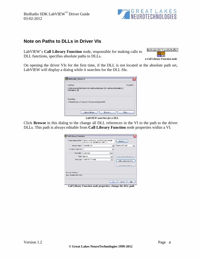
Note on Paths to DLLs in Driver VIs
LabVIEW’s Call Library Function node, responsible for making calls to
DLL functions, specifies absolute paths to DLLs.
On opening the driver VIs for the first time, if the DLL is not located at the absolute path set,
LabVIEW will display a dialog while it searches for the DLL file.
Click Browse in this dialog to the change all DLL references in the VI to the path to the driver
DLLs. This path is always editable from Call Library Function node properties within a VI.
a Call Library Function node
LabVIEW searches for a DLL
Call Library Function node properties; change the DLL path
BioRadio SDK LabVIEW™
Driver Guide
03-02-2012
Version 1.2 Page © Great Lakes NeuroTechnologies 1999-2012
5
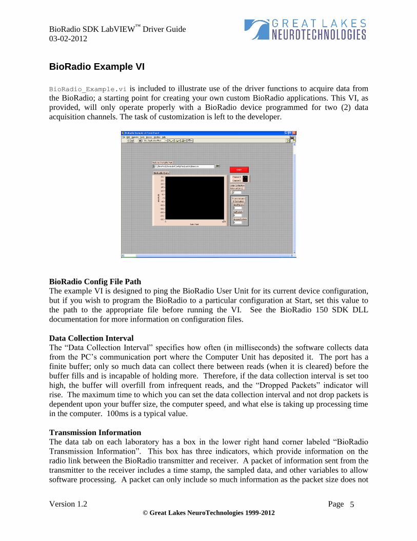
BioRadio Example VI
BioRadio_Example.vi is included to illustrate use of the driver functions to acquire data from
the BioRadio; a starting point for creating your own custom BioRadio applications. This VI, as
provided, will only operate properly with a BioRadio device programmed for two (2) data
acquisition channels. The task of customization is left to the developer.
BioRadio Config File Path The example VI is designed to ping the BioRadio User Unit for its current device configuration,
but if you wish to program the BioRadio to a particular configuration at Start, set this value to
the path to the appropriate file before running the VI. See the BioRadio 150 SDK DLL
documentation for more information on configuration files.
Data Collection Interval
The “Data Collection Interval” specifies how often (in milliseconds) the software collects data
from the PC’s communication port where the Computer Unit has deposited it. The port has a
finite buffer; only so much data can collect there between reads (when it is cleared) before the
buffer fills and is incapable of holding more. Therefore, if the data collection interval is set too
high, the buffer will overfill from infrequent reads, and the “Dropped Packets” indicator will
rise. The maximum time to which you can set the data collection interval and not drop packets is
dependent upon your buffer size, the computer speed, and what else is taking up processing time
in the computer. 100ms is a typical value.
Transmission Information
The data tab on each laboratory has a box in the lower right hand corner labeled “BioRadio
Transmission Information”. This box has three indicators, which provide information on the
radio link between the BioRadio transmitter and receiver. A packet of information sent from the
transmitter to the receiver includes a time stamp, the sampled data, and other variables to allow
software processing. A packet can only include so much information as the packet size does not

BioRadio SDK LabVIEW™
Driver Guide
03-02-2012
Version 1.2 Page © Great Lakes NeuroTechnologies 1999-2012
6
change. Therefore, if the unit is programmed for only 1 or 2 acquisition channels, a packet may
have up to 3 samples for each of channel, whereas a packet with eight channels of data will
include only one sample per channel.
Good Packets indicates the number of complete packets received from the transmitter since
starting acquisition. This number should increase rapidly while the transmitter is on. Bad
Packets indicates the number of corrupt or unreadable packets received since the start. This
number should remain extremely close to zero. Finally, Dropped Packets indicates the number
of packets sent by the User Unit, but not received or recognized. Dropped data packets can
occur for several reasons: the transmitter may be located too far from the receiver, out of
transmission range, another device may be interfering with the BioRadio signal, or the data
collection interval may be set too high. Under proper conditions, the number of dropped packets
should also remain close to zero.

BioRadio SDK LabVIEW™
Driver Guide
03-02-2012
Version 1.2 Page © Great Lakes NeuroTechnologies 1999-2012
7
Finding and Choosing Attached Devices
Overview
The first step in communicating with a BioRadio is generally to discover and identify attached
BioRadio receivers and, if multiple exist, to choose between them.
The BioRadio Find and Choose Receiver VI discovers all BioRadio receivers connected to the
user’s PC. The DLL function displays a dialog informing the user that searching is in progress,
and acts in different ways depending on the results of the search:
If exactly one BioRadio receiver is found, the
function returns the name of the device, the
number of the port to which it is attached, and
whether the BioRadio is acting as a “legacy”
COM-port device, or “non-legacy” USB.
If no BioRadio device is found, outputs reflect
this.
If multiple BioRadio devices are found, a modal
dialog (BioRadio_DialogChooseBioRadio.vi)
is presented to the user to allow selection between
the discovered devices (shown right.) The user
can choose a device, or cancel the dialog to
choose none. The appropriate information
regarding this choice is then returned by the VI
following the previous prescription.
During device discovery, a system dialog is displayed to inform the user of progress.
BioRadio SDK LabVIEW™
Driver Guide
03-02-2012
Version 1.2 Page © Great Lakes NeuroTechnologies 1999-2012
8
Finding and Choosing Attached Devices
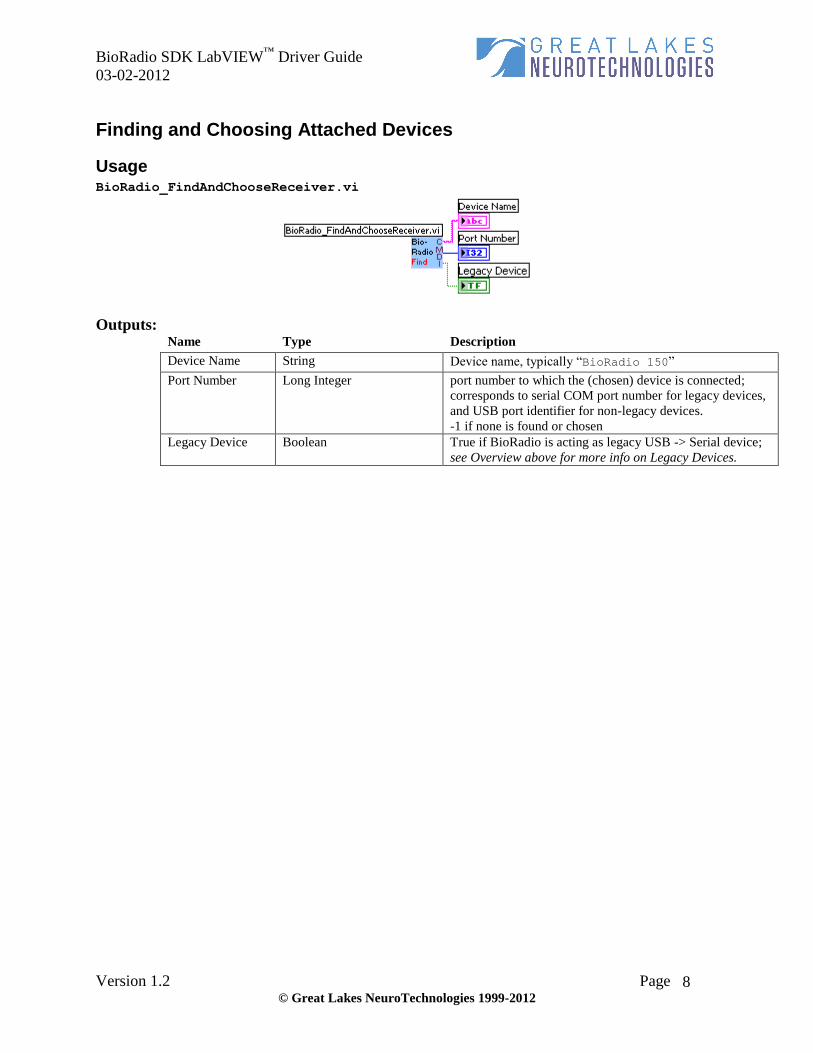
Usage BioRadio_FindAndChooseReceiver.vi
Outputs: Name Type Description
Device Name String Device name, typically “BioRadio 150”
Port Number Long Integer port number to which the (chosen) device is connected;
corresponds to serial COM port number for legacy devices,
and USB port identifier for non-legacy devices.
-1 if none is found or chosen
Legacy Device Boolean True if BioRadio is acting as legacy USB -> Serial device;
see Overview above for more info on Legacy Devices.

BioRadio SDK LabVIEW™
Driver Guide
03-02-2012
Version 1.2 Page © Great Lakes NeuroTechnologies 1999-2012
9
Starting Device Communications
Overview
Operating with the knowledge of what type of BioRadio Computer Unit is connected and on
which port, communication with the User Unit is attempted and acquisition initiated.
The BioRadio150 DLL is used to perform the following:
A BioRadio object is created (CreateBioRadio)
The value returned on dropped packets is set (SetBadDataValue)
Data acquisition is initiated (StartAcq)
Device configuration is optionally set or acquired (ProgramConfig, PingConfig)
Meta-data is gotten (GetNumChannels, GetEnabledChannels, GetSampleRate)
During Start, Programming, and Pinging of the BioRadio 150, system dialogs are displayed to
inform the user of progress.

BioRadio SDK LabVIEW™
Driver Guide
03-02-2012
Version 1.2 Page © Great Lakes NeuroTechnologies 1999-2012
10
Starting Device Communications
Usage BioRadio_StartBaseComm.vi
This vi is used to setup initial communications with the BioRadio 150 unit. For a detailed
example of its usage, see BioRadio_Example.vi
Inputs: Name Type Description Required?
PortNum Long Integer Number of port to which the device is
connected (COM Port if Legacy Device,
USB identifier if non-Legacy)
Yes
DeviceName String Device name, typically “BioRadio 150” Yes
Use Legacy
Computer Unit
Boolean Used to indicate whether you are using a
legacy CleveMed Computer Unit. If so, set
to true. Otherwise, if you are using a
CleveMed USB Receiver, set to false
Yes
Debug Boolean For internal use. This should typically be
set to false.
Yes
Outputs: Name Type Description
DeviceHandle Long Integer A unique id that is passed to other BioRadio functions to
identify the device.
PortNum Long Integer Number of port to which the device is connected (COM
Port if Legacy Device, USB identifier if non-Legacy)
DeviceName String Device name, typically “BioRadio 150”
Usage BioRadio_Start.vi
Use this vi to further initialize your BioRadio 150.

BioRadio SDK LabVIEW™
Driver Guide
03-02-2012
Version 1.2 Page © Great Lakes NeuroTechnologies 1999-2012
11
Inputs: Name Type Description Required?
PortNum Long Integer Number of port to which the device is
connected (COM Port if Legacy Device,
USB identifier if non-Legacy)
Yes
DeviceName String Device name, typically “BioRadio 150” Yes
ProgramDevice Boolean Whether the device should be programmed
to the provided configuration file upon
starting communications
Yes
BioRadio
ConfigFile Path
Path LabVIEW path variable to the configuration
file to which the device should be
programmed, if it should be programmed
If ProgramDevice
is true
BadDataValue Double-Prec. Floating-
Point
Value to which invalid/missing data should
be set (default: 0)
No
PingConfig Boolean Whether the device should be pinged and its
current configuration loaded into the object.
If ProgramDevice is set to True, PingConfig
will be ignored.
Yes
LegacyDevice Boolean This is deprecated No
Outputs: Name Type Description
NumChannels Long Integer Number of channels on which data will be acquired, based
on device configuration
Started Boolean Whether the device was successfully started
Programmed Boolean Whether the device was successfully programmed or
pinged.
Sample Rate Double-Prec. Floating-Point Samples per second, based on device configuration

BioRadio SDK LabVIEW™
Driver Guide
03-02-2012
Version 1.2 Page © Great Lakes NeuroTechnologies 1999-2012
12
Acquiring Data
Overview
Once communication with the BioRadio is established, the user will want to begin (and repeat)
acquiring data received at the PC’s communications port.
The BioRadio150 DLL is used to perform the following:
1. Instruct the device to prepare its data buffer for reading (TransferBuffer)
2. Acquire the sample rate and number of channels on which the data is being read
(GetSampleRate, GetNumChannels)
3. Establish a 655360-element array of double-precision floating-point values, initialized to
(-32768).
4. Read the data from the device’s buffer into this array (ReadScaled)
5. Multiply each data point by 1,000,000 to scale to the appropriate units.
6. De-interleave data into a 2-dimensional array whose rows correspond to input channels
7. Acquire link-status data (GetGoodPackets, GetBadPackets, GetDroppedPackets)

BioRadio SDK LabVIEW™
Driver Guide
03-02-2012
Version 1.2 Page © Great Lakes NeuroTechnologies 1999-2012
13
Acquiring Data
Usage BioRadio_Read.vi
Inputs: Name Type Description Required?
Device Name String Device name, typically “BioRadio 150” Yes
Outputs: Name Type Description
BioRadio Data 2d array of Double-Prec.
Floating-Point
Data acquired; each row of the array representing an input
channel, each column with one data point.
GoodPackets Unsigned Long Integer Number of valid packets transferred since Start
BadPackets Unsigned Long Integer Number of invalid packets transferred since Start
DroppedPackets Unsigned Long Integer Number of missed packets transferred since Start
Sample Rate Double-Prec. Floating-Point Samples/second defined by the currently loaded
configuration

BioRadio SDK LabVIEW™
Driver Guide
03-02-2012
Version 1.2 Page © Great Lakes NeuroTechnologies 1999-2012
14
Stopping Device Communications
Overview
At the end of a session, communications with the transmitter should be terminated and reserved
memory released.
The following actions are performed:
Stop BioRadio communication (StopAcq)
Destroy the BioRadio object (DestroyBioRadio)
Usage BioRadio_Stop.vi
Inputs: Name Type Description Required?
Device Name String Device name, typically “BioRadio 150” Yes