Embed Size (px)
Citation preview
BK MIKRO 8 PB
Control System for Tool Breakage and Object Monitoring with PROFIBUS Interface
Operating Instructions Issue 2.00 dated 3.2.2005
553 Industrial Dr. Hartland, WI 53029 Phone 262-367-8665 Fax 262-367-0208 web-site www.techna-tool.com email [email protected]

General Notice BA: BK MIKRO 8 PB
Seite von !Syntax Error, ; Rev. 2.00 vom 12.12.2005 ii
OI: BK MIKRO 8 PB General Notice
Rev. 2.00 dated 12.12.2005 - I -
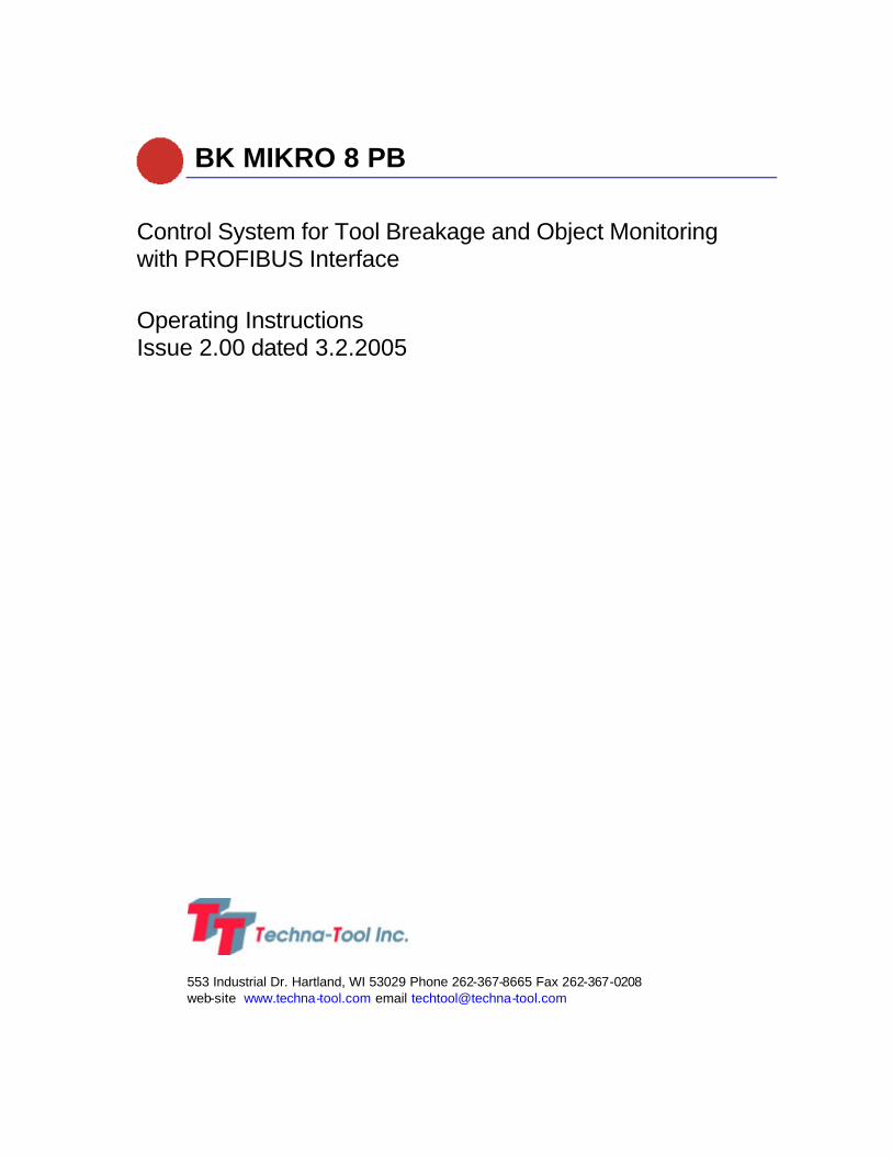
General Notice
Safety guidelines
These operating instructions contain notices which you should observe to ensure your own personal safety, as well as to protect the product and connected equipment. These notices are highlighted in the manual by a warning triangle and are marked as follows according to the level of danger:
Danger
Immediate danger
to life and limb of personnel and others.
Non-compliance may cause death or serious (crippling) injury.
Warning
Hazardous situation
to life and limb of personnel and others.
Non-compliance may cause death or serious injury.
Caution
Potentially hazardous situation
Non-compliance may cause slight injury;
possible damage to property.
Notes on correct handling Non-compliance may cause damage to the product and/or damage to parts/items in the vicinity.
Environmental protection
Non-compliance may have an impact on the environment.
Intended use
Warning
BK MIKRO is a control system suitable for tool as well as for object and free space monitoring applications. It may only be used for the applications described in the technical documents, and only in connection with devices or components from other manufacturers which have been approved or recommended by us.
This product can only function correctly and safely if it is transported, stored, set up, and installed correctly, and operated and maintained as recommended.

General Notice OI: BK MIKRO 8 PB
- II - Rev. 2.00 dated 12.12.2005
Qualification of personnel
Only qualified personnel may carry out the following activities on the control system: installation, commissioning, operation, maintenance.
Qualified persons in accordance with the safety guidelines are defined as persons who are authorized to commission, to ground, and to tag circuits, equipment, and systems in accordance with established safety practices and standards. Disclaimer of liability
We have checked the contents of this document for agreement with the hardware and software described. Since deviations cannot be precluded entirely, we cannot guarantee full agreement. However, the data in this manual are reviewed regularly and any necessary corrections included in subsequent editions. Suggestions for improvement are welcomed. EEC directive EMC 89/336/EEC
The following applies to BK MIKRO control system:
Products which carry the CE symbol meet the requirements of the EEC directive 89/336/EEC on electromagnetic compatibility.
The EEC declarations of conformity and the related documentation will be maintained at the following address for inspection by the responsible officials in accordance with article 10(1) of the above stated EEC directive:
MSC Tuttlingen GmbH Rudolf-Diesel-Straße 17 78532 Tuttlingen Areas of use
Control systems of the BK MIKRO series meet the applicable, harmonized, European standards for the respective area of applications. Fitting conditions
The fitting conditions and safety notes in the operating instructions must be adhered to when commissioning and operating the devices. Copyright
These operating instructions are intended for the operator and the operator’s personnel only. This document and its contents may not be disclosed to third parties, either in full or in part, by reproduction, transmission or any other means without express written authority.
Non-compliance may lead to prosecution under criminal law.
OI: BK MIKRO 8 PB Contents
Rev. 2.00 dated 12.12.2005 Page 1
Contents
1 Characteristics................................ ................................ ................................ ....................3
2 System Components ...........................................................................................................4 2.1 Control unit ...........................................................................................................................4 2.1.1 Technical data.......................................................................................................................5 2.1.2 Connection terminals .............................................................................................................7 2.2 Scanner................................ ................................ ................................ ................................8 2.2.1 Characteristic properties ................................ ................................ ................................ ........8 2.2.2 Technical data.......................................................................................................................9 3 PROFIBUS -DP ...................................................................................................................10 3.1 Operating mode...................................................................................................................10 3.2 Construction .......................................................................................................................11 3.3 Electric design (Physical Layer)............................................................................................12 3.3.1 Interface .............................................................................................................................12 3.3.2 LED’s to indicate status information................................ ................................ ......................13 3.3.3 Address setting...................................................................................................................13 3.4 Configuration.......................................................................................................................14 3.5 Process data: Output words 2 and 3 .....................................................................................15
Control word AW2 ...............................................................................................................15 Angle set value AW3 ...........................................................................................................15
3.6 Status words: Input words 2 and 3 ........................................................................................16 Status word EW2 ................................................................................................................16 Angle EW3 .........................................................................................................................16
3.7 Parameter...........................................................................................................................17 Parameter identification AW1 ...............................................................................................17 Parameter identification EW1 ...............................................................................................17
3.7.1 Parameter list .....................................................................................................................18 3.7.2 Declarations concerning parameters ................................ ................................ ......................19
4 Installation Notes................................ ................................ ................................ ..............21 4.1 Mounting bracket.................................................................................................................21 4.2 Interference prevention .........................................................................................................21 4.3 Tolerance Calculation:................................ ................................ ................................ ..........22
Table of Figures/Tables OI: BK MIKRO 8 PB
Page 2 Rev. 2.00 dated 12.12.2005
Table of Figures/Tables
Fig. 2-1: Control unit – front view with connections............................................................................4 Fig. 2-2: Control unit – dimensions ..................................................................................................5 Fig. 2-3: Scanner................................ ................................ ................................ ...........................9 Fig. 3-1: Construction of a typical BK MIKRO 8 PB system................................ ............................. 11 Fig. 3-1: PROFIBUS -DP interfae ................................................................................................... 12 Fig. 3-2: Light-emitting diodes....................................................................................................... 13 Fig. 3-3: DIP switch S1 ................................................................................................................ 13 Tab. 3-4: Parameter list ................................................................................................................ 18 Fig. 4-1: Mounting bracket............................................................................................................ 21
Appendix A Model 8 Manufacturing and Techna-Tool Part Numbers...................................................... 23
Purpose
These operating instructions are part of the documentation of the BK MIKRO 8 PB. They provide service personnel and system advisors with the information required to install, commission, operate and maintain the BK MIKRO 8 PB.
© Copyright MSC Tuttlingen GmbH, 78532 Tuttlingen, 2002
These operating instructions are available as article no. 68 36 239.
Subject to change without notice.
OI: BK MIKRO 8 PB Copyright
Rev. 2.00 dated 12.12.2005 Page 3
1 Characteristics
BK MIKRO 8 PB is a control system suitable for tool as well as for object and free space monitoring applications.
The complete BK MIKRO 8 PB system comprises
• a control unit
• a sensor (scanner),
• a connection cable.
BK MIKRO 8 PB is based on existing design concepts for tool, object and free space monitoring and can be used universally for different types of monitoring by the integration of multifarious functions:
• Object monitoring, Tool monitoring, free space monitoring with PROFIBUS connection. Tool monitoring with specification (angle/tolerance) of PROFIBUS master (SPS/PLC)
• Tool monitoring without PROFIBUS connection. Monitoring of the scanning position whose precise location has been previously entered by "Teach-in", e.g. to carry out a tool check before each working cycle. Through five selection inputs up to 32 tools can be learned and monitored.
Principle of operation
The wand of the scanner scans tools, objects or critical process spaces free of potential, in line with machine cycles.
A control unit equipped with a micro-computer triggers the movement of the wand upon an external signal or about a PROFIBUS message and passes the scanning result and PROFIBUS messages on to the machine control via relay contacts.
The galvanically isolated inputs and outputs guarantee a high degree of operational safety and protection against interferences.
Further features
• Scanning in clockwise (CW) or counter-clockwise (CCW) direction
• Two steps for scanning intensity
• Output relay contacts selectable as normally open or norm ally closed
• Ranges of tolerance for "O.K." message adjustable
• Indication of the scanning result by two LED’s "O.K." and "K.O." on the control unit
• Detection of cable breaks
BA: BK MIKRO 8 PB Copyright
Page 4 Rev. 2.00 dated 12.12.2005
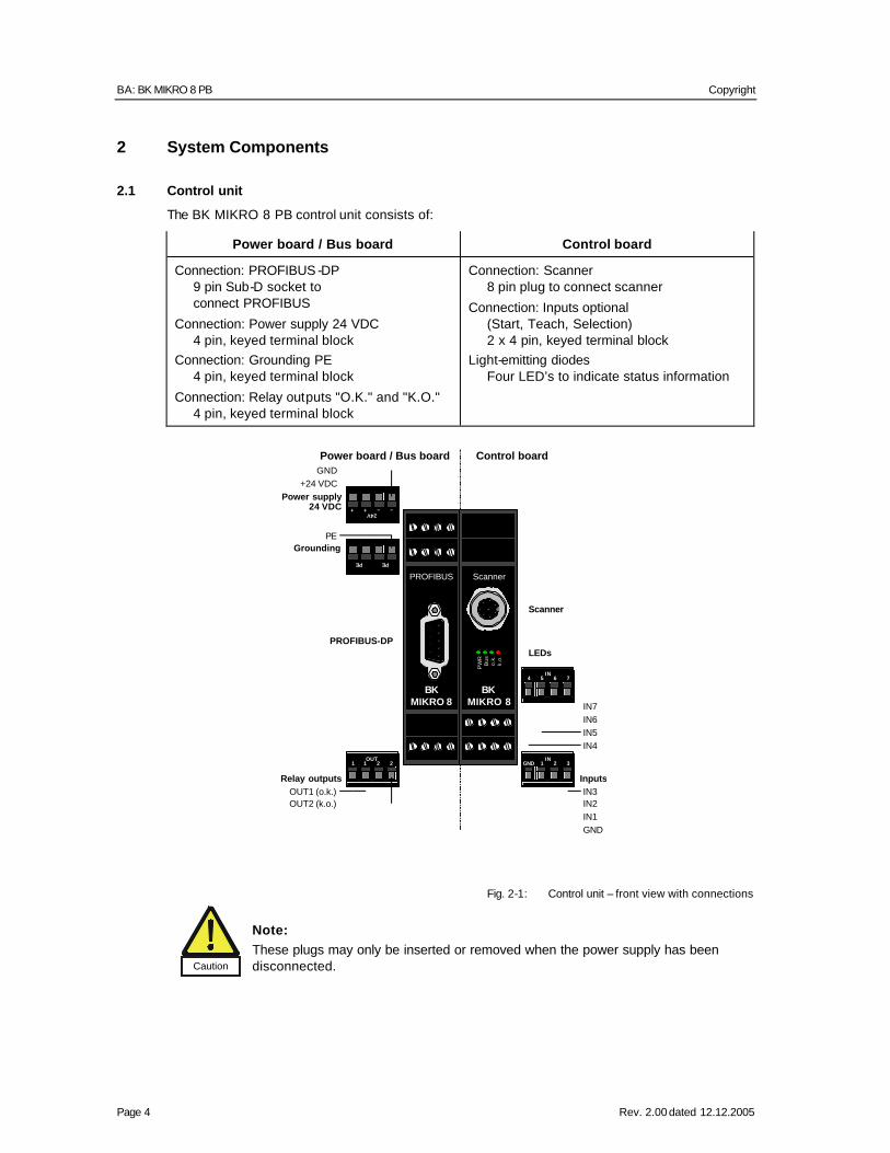
2 System Components
2.1 Control unit
The BK MIKRO 8 PB control unit consists of:
Power board / Bus board Control board
Connection: PROFIBUS -DP 9 pin Sub-D socket to connect PROFIBUS
Connection: Power supply 24 VDC 4 pin, keyed terminal block
Connection: Grounding PE 4 pin, keyed terminal block
Connection: Relay outputs "O.K." and "K.O." 4 pin, keyed terminal block
Connection: Scanner 8 pin plug to connect scanner
Connection: Inputs optional (Start, Teach, Selection) 2 x 4 pin, keyed terminal block
Light-emitting diodes Four LED’s to indicate status information
Fig. 2-1: Control unit – front view with connections
Caution
Note: These plugs may only be inserted or removed when the power supply has been disconnected.
PW
RB
uso.
k.k.
o.
PROFIBUS Scanner
BKMIKRO 8
BKMIKRO 8
+24V
+ – –
PE PE
3IN
21GND2OUT
211
Scanner
PROFIBUS-DP
OUT1 (o.k.) IN3
IN1
PE
Relay outputs Inputs
LEDs
GND
OUT2 (k.o.) IN2
GND
Control boardPower board / Bus board
+24 VDC
Grounding
Power supply 24 VDC
7IN
654
IN7
IN5IN6
IN4
OI: BK MIKRO 8 PB Copyright
Rev. 2.00 dated 12.12.2005 Page 5
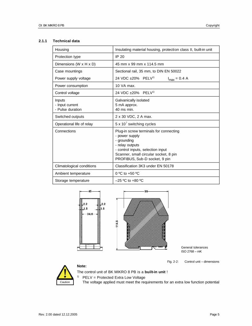
2.1.1 Technical data
Housing Insulating material housing, protection class II, built-in unit
Protection type IP 20
Dimensions (W x H x D) 45 mm x 99 mm x 114.5 mm
Case mountings Sectional rail, 35 mm, to DIN EN 50022
Power supply voltage 24 VDC ±20% PELV1) Imax = 0.4 A
Power consumption 10 VA max.
Control voltage 24 VDC ±20% PELV1)
Inputs - Input current - Pulse duration
Galvanically isolated 5 mA approx. 40 ms min.
Switched outputs 2 x 30 VDC, 2 A max.
Operational life of relay 5 x 10⁷ switching cycles
Connections Plug-in screw terminals for connecting - power supply - grounding - relay outputs - control inputs, selection input Scanner, small circular socket, 8 pin PROFIBUS, Sub-D socket, 9 pin
Climatological conditions Classification 3K3 under EN 50178
Ambient temperature 0 ºC to +50 ºC
Storage temperature –25 ºC to +80 ºC
General tolerances ISO 2768 – mK
Fig. 2-2: Control unit – dimensions
Caution
Note:
The control unit of BK MIKRO 8 PB is a built-in unit ! 1) PELV = Protected Extra Low Voltage
The voltage applied must meet the requirements for an extra low function potential

BA: BK MIKRO 8 PB Copyright
Page 6 Rev. 2.00 dated 12.12.2005
with safe disconnection (PELV).
OI: BK MIKRO 8 PB 24V – power supply 24 VDC
Rev. 2.00 dated 12.12.2005 Page 7
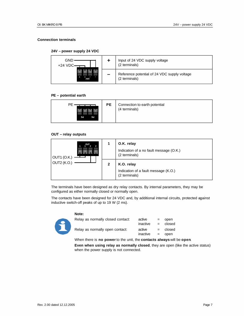
Connection terminals
24V – power supply 24 VDC
+ Input of 24 VDC supply voltage (2 terminals)
+24V
+ – –
GND+24 VDC
– Reference potential of 24 VDC supply voltage (2 terminals)
PE – potential earth
PE PE
PE
PE Connection to earth potential (4 terminals)
OUT – relay outputs
1 O.K. relay
Indication of a no fault message (O.K.) (2 terminals)
2OUT
211
OUT1 (O.K.)OUT2 (K.O.) 2 K.O. relay
Indication of a fault message (K.O.) (2 terminals)
The terminals have been designed as dry relay contacts. By internal parameters, they may be configured as either normally closed or normally open.
The contacts have been designed for 24 VDC and, by additional internal circuits, protected against inductive switch-off peaks of up to 19 W (2 ms).
Note: Relay as normally closed contact: active = open inactive = closed
Relay as normally open contact: active = closed inactive = open
When there is no power to the unit, the contacts always will be open.
Even when using relay as normally closed, they are open (like the active status) when the power supply is not connected.
BA: BK MIKRO 8 PB
Page 8 Rev. 2.00 dated 12.12.2005
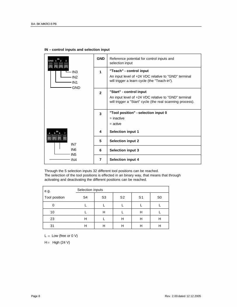
IN – control inputs and selection input
GND Reference potential for control inputs and selection input
1 "Teach" - control input
An input level of +24 VDC relative to "GND" terminal will trigger a learn cycle (the "Teach-in").
2 "Start" - control input
An input level of +24 VDC relative to "GND" terminal will trigger a "Start" cycle (the real scanning process).
3IN
21GND
IN3
IN1IN2
GND
3 "Tool position" - selection input 0
= inactive
= active
4 Selection input 1
5 Selection input 2
6 Selection input 3
7IN
654
IN7
IN5IN6
IN4 7 Selection input 4
Through the 5 selection inputs 32 different tool positions can be reached. The selection of the tool positions is effected in an binary way, that means that through activating and deactivating the different positions can be reached.
Selection inputs e.g.
Tool position S4 S3 S2 S1 S0
0 L L L L L
10 L H L H L
23 H L H H H
31 H H H H H
L Low (free or 0 V)
H High (24 V)
= ∧
= ∧
OI: BK MIKRO 8 PB IN – control inputs and selection input
Rev. 2.00 dated 12.12.2005 Page 9
2.2 Scanner
2.2.1 Characteristic properties
The scanner housing is cylindrical and smooth, thus permitting easy installation (e.g. by using the mounting bracket). The scanner is designed for easy access for servicing and changing the wand. Aligning the scanner is easy and requires no additional instruments or aids.
The BK8SC scanner offers two special features:
• Scanning wands up to a length of 380 mm allow if required greater distance between tool and/or object and scanner.
• Scanning plate at the scanning wand makes it possible to use the scanner directly at the tool magazine to control the tool's tip. The BK8SC scanner has a mechanical backstop that limits the rotary movement of the wand.
Using scanner BK8SC with a different control unit than BK MIKRO 8 PB may damage the scanner and control unit.
Warning
Note:
The wand is a wearing part.
Due to the injury hazard, users should exercise particular caution within any BK MIKRO rotating area.
BA: BK MIKRO 8 PB IN – control inputs and selection input
Page 10 Rev. 2.00 dated 12.12.2005
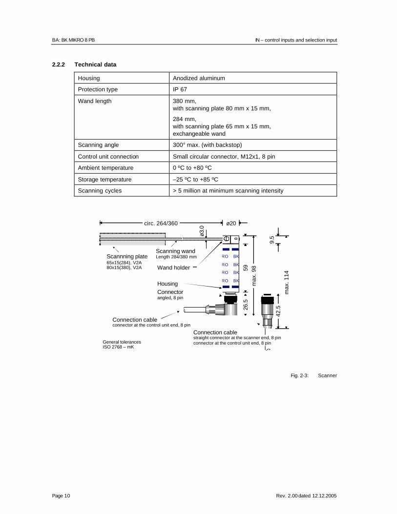
2.2.2 Technical data
Housing Anodized aluminum
Protection type IP 67
Wand length 380 mm, with scanning plate 80 mm x 15 mm,
284 mm, with scanning plate 65 mm x 15 mm, exchangeable wand
Scanning angle 300° max. (with backstop)
Control unit connection Small circular connector, M12x1, 8 pin
Ambient temperature 0 ºC to +80 ºC
Storage temperature –25 ºC to +85 ºC
Scanning cycles > 5 million at minimum scanning intensity
Fig. 2-3: Scanner
BK
BK
BK
BKRO
RO
RO
RO
ø3.0
59
ø20
26.
5
42.
5 9
.5
Connectorangled, 8 pin
Housing
Wand holder
Scanning wandLength 284/380 mm
max
. 98
max
. 114
Scannning plate65x15(284), V2A80x15(380), V2A
General tolerances ISO 2768 – mK
Connection cablestraight connector at the scanner end, 8 pinconnector at the control unit end, 8 pin
Connection cableconnector at the control unit end, 8 pin
circ. 264/360
OI: BK MIKRO 8 PB IN – control inputs and selection input
Rev. 2.00 dated 12.12.2005 Page 11
3 PROFIBUS-DP
3.1 Operating mode
BK MIKRO 8 PB can be employed in two operating modes.
• With PROFIBUS interface • Operation about external switching inputs (without PROFIBUS) If a tool (e.g. a drill) is to be checked, the control system calculates the corresponding angle of the scanning wand by the tool length stored in the tool database and transmit this value via PROFIBUS to control unit. After that the scanning can be started by the bit "Start".
If the scanning wand hits on of an object within the measuring range an O.K. message is output about the PROFIBUS, simultaneously is put also the exit (o.k.)
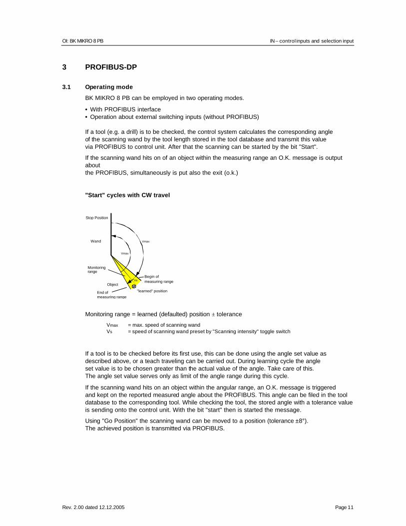
"Start" cycles with CW travel
Monitoring range = learned (defaulted) position ± tolerance
Vmax = max. speed of scanning wand Vs = speed of scanning wand preset by "Scanning intensity" toggle switch
If a tool is to be checked before its first use, this can be done using the angle set value as described above, or a teach traveling can be carried out. During learning cycle the angle set value is to be chosen greater than the actual value of the angle. Take care of this. The angle set value serves only as limit of the angle range during this cycle.
If the scanning wand hits on an object within the angular range, an O.K. message is triggered and kept on the reported measured angle about the PROFIBUS. This angle can be filed in the tool database to the corresponding tool. While checking the tool, the stored angle with a tolerance value is sending onto the control unit. With the bit "start" then is started the message.
Using "Go Position" the scanning wand can be moved to a position (tolerance ±8°). The achieved position is transmitted via PROFIBUS.
Stop Position
"learned" position
Object
Monitoring range
Vmax
Vmax
Wand
VsBegin of measuring range
End of measuring range
BA: BK MIKRO 8 PB IN – control inputs and selection input
Page 12 Rev. 2.00 dated 12.12.2005
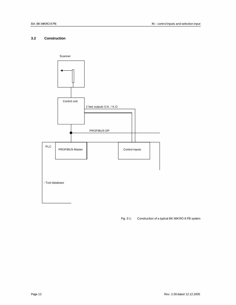
3.2 Construction
Fig. 3-1: Construction of a typical BK MIKRO 8 PB system
Scanner
Control unit
2 fast outputs O.K. / K.O.
PROFIBUS-DP
PLCPROFIBUS-Master Control inputs
- Tool database
OI: BK MIKRO 8 PB IN – control inputs and selection input
Rev. 2.00 dated 12.12.2005 Page 13
3.3 Electric design (Physical Layer)
3.3.1 Interface
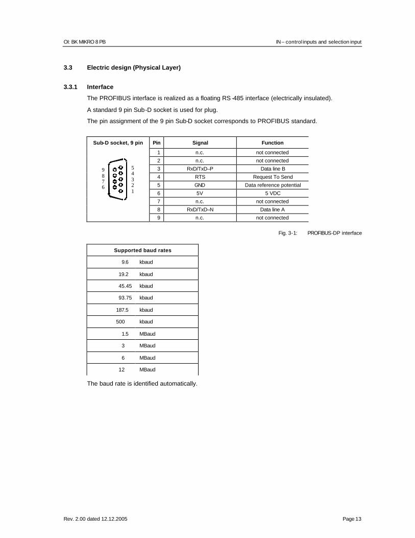
The PROFIBUS interface is realized as a floating RS -485 interface (electrically insulated).
A standard 9 pin Sub-D socket is used for plug.
The pin assignment of the 9 pin Sub-D socket corresponds to PROFIBUS standard.
Sub-D socket, 9 pin Pin Signal Function
1 n.c. not connected
2 n.c. not connected
3 RxD/TxD–P Data line B
4 RTS Request To Send
5 GND Data reference potential
6 5V 5 VDC
7 n.c. not connected
8 RxD/TxD–N Data line A
9 n.c. not connected
Fig. 3-1: PROFIBUS-DP interface
Supported baud rates
9.6 kbaud
19.2 kbaud
45.45 kbaud
93.75 kbaud
187.5 kbaud
500 kbaud
1.5 MBaud
3 MBaud
6 MBaud
12 MBaud
The baud rate is identified automatically.
12345
6789
BA: BK MIKRO 8 PB Example:
Page 14 Rev. 2.00 dated 12.12.2005
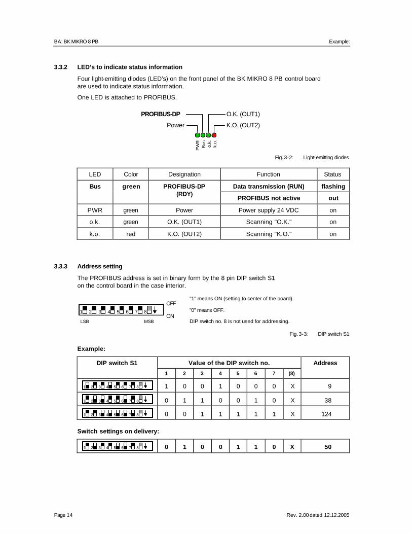
3.3.2 LED’s to indicate status information
Four light-emitting diodes (LED’s) on the front panel of the BK MIKRO 8 PB control board are used to indicate status information.
One LED is attached to PROFIBUS.
Fig. 3-2: Light-emitting diodes
LED Color Designation Function Status
Bus green Data transmission (RUN) flashing
PROFIBUS-DP (RDY)
PROFIBUS not active out
PWR green Power Power supply 24 VDC on
o.k. green O.K. (OUT1) Scanning "O.K." on
k.o. red K.O. (OUT2) Scanning "K.O." on
3.3.3 Address setting
The PROFIBUS address is set in binary form by the 8 pin DIP switch S1 on the control board in the case interior.
"1" means ON (setting to center of the board).
"0" means OFF.
DIP switch no. 8 is not used for addressing.
Fig. 3-3: DIP switch S1 Example:
DIP switch S1 Value of the DIP switch no. Address 1 2 3 4 5 6 7 (8)
1 2 3 4 5 6 7 8 1 0 0 1 0 0 0 X 9
1 2 3 4 5 6 7 8 0 1 1 0 0 1 0 X 38
1 2 3 4 5 6 7 8 0 0 1 1 1 1 1 X 124
Switch settings on delivery:
1 2 3 4 5 6 7 8 0 1 0 0 1 1 0 X 50
1 2 3 4 5 6 7 8
OFF
ONLSB MSB
PW
RB
us o.k.
k.o.
Power
PROFIBUS-DP
K.O. (OUT2)
O.K. (OUT1)
OI: BK MIKRO 8 PB Switch settings on delivery:
Rev. 2.00 dated 12.12.2005 Page 15
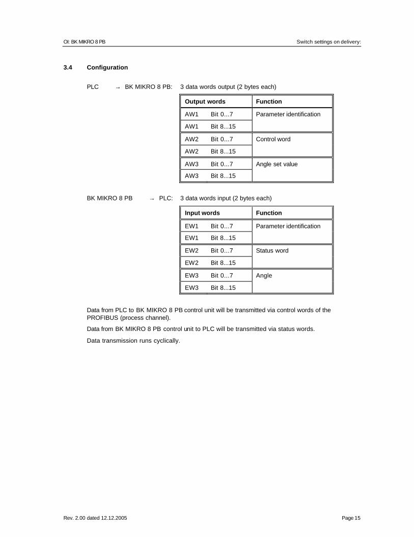
3.4 Configuration
PLC → BK MIKRO 8 PB: 3 data words output (2 bytes each)
Output words Function
AW1 Bit 0...7 Parameter identification
AW1 Bit 8...15
AW2 Bit 0...7 Control word
AW2 Bit 8...15
AW3 Bit 0...7 Angle set value
AW3 Bit 8...15
BK MIKRO 8 PB → PLC: 3 data words input (2 bytes each)
Input words Function
EW1 Bit 0...7 Parameter identification
EW1 Bit 8...15
EW2 Bit 0...7 Status word
EW2 Bit 8...15
EW3 Bit 0...7 Angle
EW3 Bit 8...15
Data from PLC to BK MIKRO 8 PB control unit will be transmitted via control words of the PROFIBUS (process channel).
Data from BK MIKRO 8 PB control unit to PLC will be transmitted via status words.
Data transmission runs cyclically.
BA: BK MIKRO 8 PB From PLC to BK MIKRO 8 PB control unit
Page 16 Rev. 2.00 dated 12.12.2005
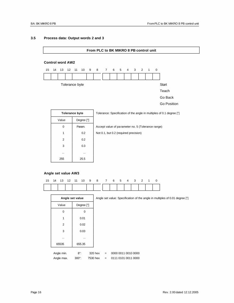
3.5 Process data: Output words 2 and 3
From PLC to BK MIKRO 8 PB control unit
Control word AW2
15 14 13 12 11 10 9 8 7 6 5 4 3 2 1 0
Tolerance byte Start Teach
Go Back Go Position
Tolerance byte Tolerance: Specification of the angle in multiples of 0.1 degree [°]
Value Degree [°]
0 Param. Accept value of parameter no. 5 (Tolerance range)
1 0.2 Not 0.1, but 0.2 (required precision)
2 0.2
3 0.3
... ...
255 25.5
Angle set value AW3
15 14 13 12 11 10 9 8 7 6 5 4 3 2 1 0
Angle set value Angle set value: Specification of the angle in multiples of 0.01 degree [°]
Value Degree [°]
0 0
1 0.01
2 0.02
3 0.03
... ...
65535 655.35
Angle min. 8°: 320 hex = 0000 0011 0010 0000
Angle max. 300°: 7530 hex = 0111 0101 0011 0000
OI: BK MIKRO 8 PB From BK MIKRO 8 PB control unit to PLC
Rev. 2.00 dated 12.12.2005 Page 17
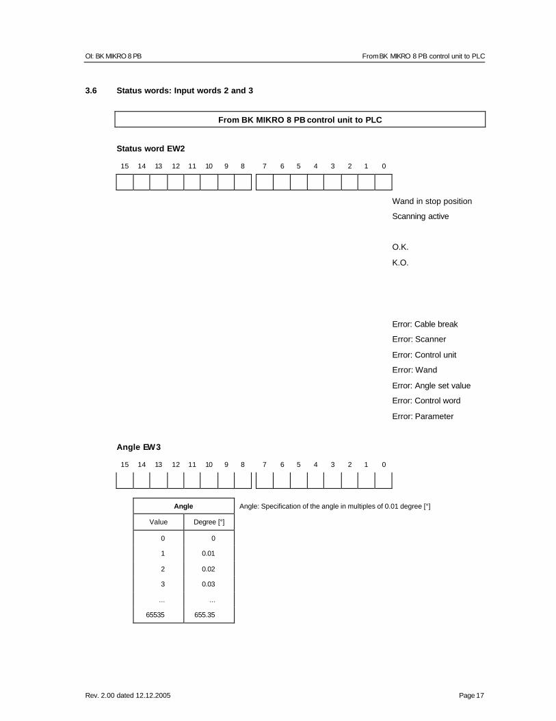
3.6 Status words: Input words 2 and 3
From BK MIKRO 8 PB control unit to PLC
Status word EW2
15 14 13 12 11 10 9 8 7 6 5 4 3 2 1 0
Wand in stop position Scanning active
O.K.
K.O.
Error: Cable break Error: Scanner
Error: Control unit Error: Wand
Error: Angle set value Error: Control word
Error: Parameter Angle EW3
15 14 13 12 11 10 9 8 7 6 5 4 3 2 1 0
Angle Angle: Specification of the angle in multiples of 0.01 degree [°]
Value Degree [°]
0 0
1 0.01
2 0.02
3 0.03
... ...
65535 655.35
BA: BK MIKRO 8 PB From PLC to BK MIKRO 8 PB control unit
Page 18 Rev. 2.00 dated 12.12.2005
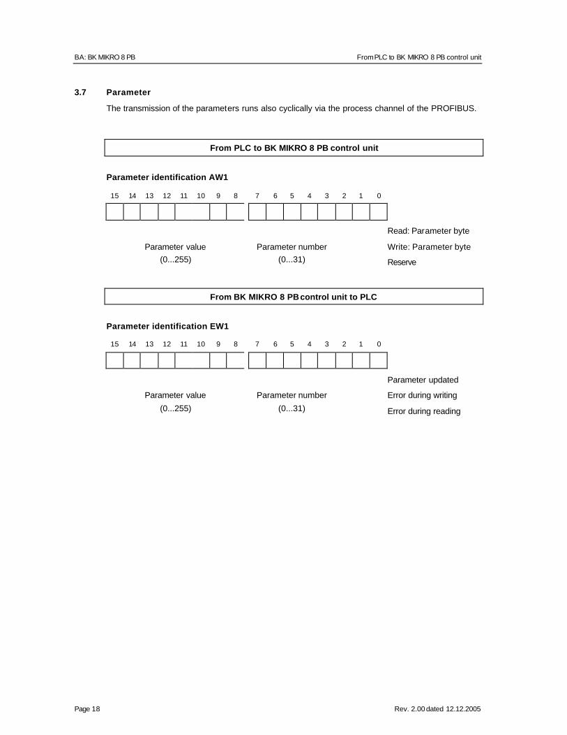
3.7 Parameter
The transmission of the parameters runs also cyclically via the process channel of the PROFIBUS.
From PLC to BK MIKRO 8 PB control unit
Parameter identification AW1
15 14 13 12 11 10 9 8 7 6 5 4 3 2 1 0
Read: Parameter byte
Parameter value Parameter number Write: Parameter byte (0...255) (0...31) Reserve
From BK MIKRO 8 PB control unit to PLC
Parameter identification EW1
15 14 13 12 11 10 9 8 7 6 5 4 3 2 1 0
Parameter updated
Parameter value Parameter number Error during writing
(0...255) (0...31) Error during reading
OI: BK MIKRO 8 PB From BK MIKRO 8 PB control unit to PLC
Rev. 2.00 dated 12.12.2005 Page 19
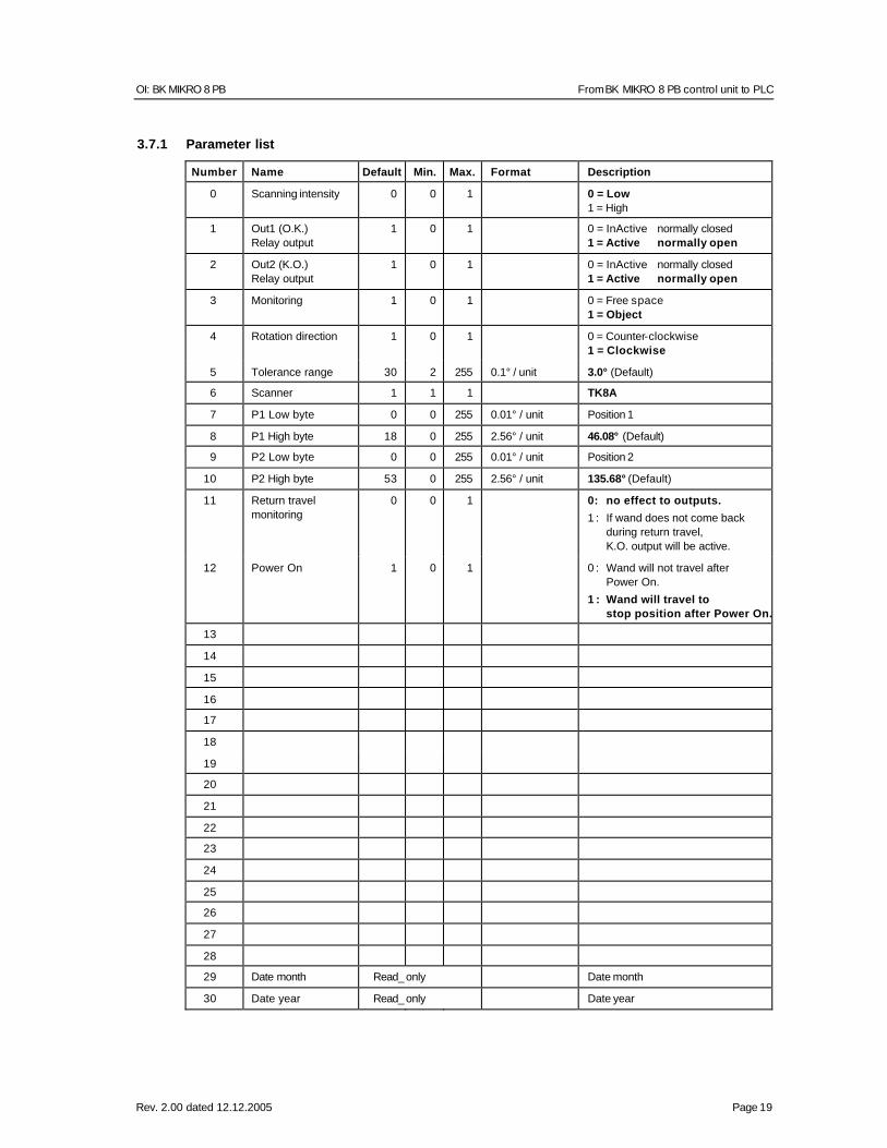
3.7.1 Parameter list
Number Name Default Min. Max. Format Description
0 Scanning intensity 0 0 1 0 = Low 1 = High
1 Out1 (O.K.) Relay output
1 0 1 0 = InActive normally closed 1 = Active normally open
2 Out2 (K.O.) Relay output
1 0 1 0 = InActive normally closed 1 = Active normally open
3 Monitoring 1 0 1 0 = Free space 1 = Object
4 Rotation direction 1 0 1 0 = Counter-clockwise 1 = Clockwise
5 Tolerance range 30 2 255 0.1° / unit 3.0° (Default)
6 Scanner 1 1 1 TK8A
7 P1 Low byte 0 0 255 0.01° / unit Position 1
8 P1 High byte 18 0 255 2.56° / unit 46.08° (Default)
9 P2 Low byte 0 0 255 0.01° / unit Position 2
10 P2 High byte 53 0 255 2.56° / unit 135.68° (Default)
11 Return travel monitoring
0 0 1 0: no effect to outputs.
1 : If wand does not come back during return travel, K.O. output will be active.
12 Power On 1 0 1 0 : Wand will not travel after Power On.
1 : Wand will travel to stop position after Power On.
13
14
15
16
17
18
19
20
21
22
23
24
25
26
27
28
29 Date month Read_ only Date month
30 Date year Read_ only Date year

BA: BK MIKRO 8 PB From BK MIKRO 8 PB control unit to PLC
Page 20 Rev. 2.00 dated 12.12.2005
31 Version Read_ only Software version
Tab. 3-4: Parameter list
OI: BK MIKRO 8 PB From BK MIKRO 8 PB control unit to PLC
Rev. 2.00 dated 12.12.2005 Page 21
3.7.2 Declarations concerning parameters
The table shows the allocation of parameters 0 ... 31.
There are parameters that can be read and to which can be written, as well as read-only parameters that can only be read.
An attempt to write a read-only parameter causes an error message.
• Scanning intensity Scanning intensity determines permissible force and permissible speed during learning cycle and/or within tolerance range of start cycle. There are two steps of setting.
• Out1 and Out2 Using these parameters relay output 1 (O.K.) and/or relay output 2 (K.O.) can be defined, as it will operate in the "active" state. After switch-on these outputs are always on the set state "normally closed" or "normally open" without a scanning has occurred before.
• Monitoring Using this parameter, monitoring mode can be set to object monitoring or free space monitoring. - In case of object monitoring an object will be scanned, and if the object is detected in the
defaulted area the O.K. output will be activated, or if the object is not detected the K.O. output will be activated.
- In case of free space monitoring it will be checked whether the predefined area can be scanned by the wand without detecting an obstacle.
This monitoring mode does not allow any learning cycle.
Monitoring ranges are defined either by angle set value and tolerance set value or by parameters position P1 and P2.
- For tolerance 0, +/– the parameter value "Tolerance range" is used as tolerance range.
- For angle set value 0, P1 and P2 are used as tolerance range.
• Rotation direction Using this parameter the scanning direction can be changed. As soon as the parameter is changed, the wand starts to the "new stop position" and will set a "new" reference position.
• Tolerance range The tolerance range can be set by this parameter. With this information the toleranc e range has not to be set in start cycle. Tolerance range = 0 in control word: +/– parameter value is used as tolerance range.
BA: BK MIKRO 8 PB
Page 22 Rev. 2.00 dated 12.12.2005
• Scanner Settings of the scanner (for further applications).
• Position 1: P1 Low byte, P1 High byte and Position 2: P2 Low byte, P2 High byte Using these parameters the angle set value can be preset by P1 and P2.
These values are used as range set value as soon as angle set value = 0.
• Return travel monitoring Using this parameter the O.K. output can be activated in case of non-attaining the stop position. If return travel monitoring is not active, this information can also be interrogated in bit "Wand in stop position" via PROFIBUS.
• Power On Using this parameter it can be prevented that the wand starts moving immediately after switch-on of the power supply. Usually set parameter to 0: Default!
OI: BK MIKRO 8 PB
Rev. 2.00 dated 12.12.2005 Page 23
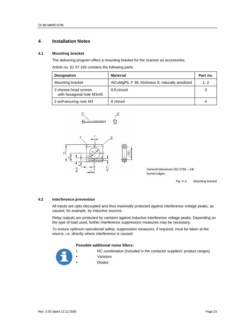
4 Installation Notes
4.1 Mounting bracket
The delivering program offers a mounting bracket for the scanner as accessories.
Article no. 61 07 165 contains the following parts:
Designation Material Part no.
Mounting bracket AlCuMgPb, F 38, thickness 8, naturally anodized 1, 2
2 cheese head screws with hexagonal hole M3x40
8.8 zinced 3
2 self-securing nuts M3 8 zinced 4
General tolerances ISO 2768 – mK burred edges
Fig. 4-1: Mounting bracket
4.2 Interference prevention
All inputs are opto-decoupled and thus maximally protected against interference voltage peaks, as caused, for example, by inductive sources.
Relay outputs are protected by varistors against inductive interference voltage peaks. Depending on the type of load used, further interference suppression measures may be necessary.
To ensure optimum operational safety, suppression measures, if required, must be taken at the source, i.e. directly where interference is caused.
Possible additional noise filters:
• RC combination (included in the contactor suppliers' product ranges) • Varistors
• Diodes

BA: BK MIKRO 8 PB
Page 24 Rev. 2.00 dated 12.12.2005
4.3 Tolerance Calculation:
Use the Angle (A) that you want the tolerance to be (the range is selectable between 0.2 and 25.5 degrees ) multiply this by p and divide by 180. Take the answer and multiply by the length of the wand you will be using. This will give the ± tolerance in inches or mm depending on which you used for the length of the wand. Ap/180 = Answer Answer X Length = ± Tolerance
Appendix A Model 8 Manufacturing and Techna -Tool Part Numbers
Mfg. Techna -Tool Part Number Part Number Description TK8A.xx BK8SC BK Mikro Model 8 Scanner 63 04 236 BK 824-PROFI BK Mikro Model 8 24V input Controller