Embed Size (px)
Citation preview

1
Blackstart of An Induction Motor in AnAutonomous Microgrid
Ahmad Tazay, Zhixin Miao, Senior Member, IEEE, and Lingling Fan, Senior Member, IEEE
Abstract—Starting of large induction motors may producevoltage dip in a weak microgrid because of high current andreactive power demand in transient period. This paper developsa solution for black start issue of an Induction Motor (IM)using Voltage-Sourced Converter (VSC) interfaced source inan autonomous microgrid. This paper provides procedures andtechniques for controlling the VSC. First, a dynamic modelof a microgrid is analyzed to provide a designing criteria ofVSC’s controller. Vector control is implemented to control thevoltage and frequency of the VSC at autonomous mode. Second,the issue of black start of IM is investigated and analyzed. Aproposed technique is presented in order to solve the overcurrentand voltage dip due to black start of IM. Finally, a microgridis modeled and simulated in PSCAD/EMTDC to validate theproposed technique on black start.
Index Terms—Microgrid, Autonomous Mode, Vector Control,Voltage-Sourced Converter (VSC), V/F Control, Black Start,Inrush Current, Soft Start.
I. INTRODUCTION
Power electronics play an important role in converting DCpower into AC power from distributed generators (DGs) tocontrollable loads. VSC is one of the commonly used powerelectronic devices that are recently implemented in controllinga microgrid due to several advantages such as independentcontrol of voltage and frequency, possibility to be connectedto weak ac grid and ability to mitigate the negative effect ofdisturbance [1]–[3].
Active loads such as induction motors occupy almost 50%of all loads in real applications [4]. The major problem ofoperating large IM is voltage dip in case of a weak system.
Three important elements have to be considered in the caseof blackstart of IM that involve starting current, reactive powerconsumption, and voltage dip. First, the high consuming cur-rent during start-up condition is the main reason of blackstart.This current may absorb almost five to ten times the ratedcurrent. Second, the motor consumes high reactive powerduring the start-up condition because of high starting current.Finally, high starting current could generate voltage dip whichwill affect the IM torque since the torque is promotional to thesquare value of the voltage. It also may affect other loads andthe system’s stability. According to IEEE, the acceptable rangeof voltage dip during starting motors is between 80% to 90%of the full rated voltage [4]. Voltage dip is the major concernin starting motors in case of weak autonomous microgrid.
Different methods have been used to reduce the negative
L. Fan, Z. L. Miao, and A. are with the Department of Electrical Engineer-ing, University of South Florida, Tampa, FL 33620 USA (e-mail: [email protected]; [email protected]; [email protected]).
effect of starting large motor [5]. In case of small motors,Direct-On-Line (DOL) method is used because of low con-suming reactive power and starting current. In case of largeinduction motors, reducing applied voltage or providing higherreactive power is needed to avoid voltage dip during startingperiod of the motor [4]–[6].
In this paper, the strategy of reducing applied voltage duringIM startup will be applied in an autonomous microgrid. AnIM will be served by a VSC interfaced voltage source duringstartup. Though VSC control, blackstart of the IM withoutovercorrect will be realized.
The rest of the paper is organized as follows. Section IIdescribes the system design and control concept of VSCbased autonomous microgrid. It also develops mathematicalmodel and tuning techniques of the transfer function equations.Section III studies and analyzes the behavior of the systemwhen IM connected to a weak microgrid. It also provides aproposed technique to control of IM during start-up condition.Section IV tests the performance of the designing controllerand proposed technique by using PSCAD/EMTDC softwaresimulation. Section V concludes and summarizes the mainpoints of the paper.
II. V/F CONTROL OF VSC IN AN AUTONOMOUSMICROGRID
A. V/F Plant Model
Vector control methodology is used to control voltage andfrequency of VSC [7]–[9]. A schematic controller design ofVSC at an autonomous microgrid is shown in Fig. 1. Theconcept of vector control depends on transferring symmetricalsignals from three-phase time domain into two-phase rotatingsynchronous reference frame. The direct transformation ofthree-phase sinusoidal signal into two-phase constant signalis calculated by using Park’s transformation [10].
The dynamic equations of the system in Fig. 1 are analyzedto find the states and controlled variables of VSC. Two maincomponents need to be controlled which are output currentand voltage of VSC. KVL and KCL are applied to find thedynamic equations of the inner current loop and outer voltageloop, respectively as follows:
LdiLabc
dt= −Riabc + Vsabc
− Epccabc(1)
CdVCabc
dt= iabc − ilabc (2)

2
M
Vector Controller in DQ
Fig. 1. General scheme of a VSC using vector control.
The current and voltage equations in Eqns. (1) and (2) aretransferred into DQ reference frame as follows:
CdVsddt
= CωVsq + id − ild (3)
CdVsqdt
= −CωVsd + iq − ilq (4)
Ldiddt
= −Rid + Lω(t)iq + Vsd (5)
Ldiqdt
= −Riq − Lω(t)id + Vsq (6)
Controlling the inner and outer loops is applied in Laplace-domain. The current equations in Laplace-domain are shownas:
id =1
Ls+Ruid(s) (7)
iq =1
Ls+Ruiq(s) (8)
Where
uid(s) = −Lωiq(s) + Vsd(s) (9)uiq(s) = +Lωid(s) + Vsq(s) (10)
The inner current control design is shown in Fig. 2 where Kid
and Kiq are the PI-compensators in DQ reference frame.The dynamic equations of the voltage controller in Laplace-
Fig. 2. Simplified control block diagram of the inner current loop.
domain are obtained as:
Vsd(s) =1
Csuvd(s)Gi(s) (11)
Vsq(s) =1
Csuvq(s)Gi(s) (12)
where
uvd = −CωVCq + ild (13)uvq = +CωVCd + ilq (14)
Gi(s) =1
1 + τis(15)
The outer voltage control block is shown in Fig. 3 based onEqns. (9), (10), (11), and (12) where Kvd and Kvq are thePI-compensators in DQ reference frame.
Fig. 3. Simplified control block diagram of the outer voltage loop.
B. Controller Design
Designing V/F controller basically depends on determiningthe optimal operating structure of the system and regulatingthe compensators. These elements have to accomplish stability,fast response and disturbance rejection. Since all signals aretransferred into DQ reference, PI controller is a sufficientcompensator to provide zero steady state error. The open-looptransfer function of the inner current controller is obtainedfrom Fig. 2 and illustrated as:
li(s) = Ki(s)Pi(s)
=
(kip +
kiis
)1
Ls+R(16)
where Ki(s) and Pi(s) are the transfer functions of thecontroller’s compensator and plant.
The order of the closed-loop transfer function of the cur-rent is less than 3 which is recommended to use “ModulusOptimum” technique [11]. This method is suitable to tune theparameters of the inner current compensator because of itssimplicity and accuracy.
The open-loop transfer function of the current is obtainedfrom Fig. 3 as follows:
li = Kip
(s+ Kii
Kip
s
)1
L(s+ RL )
(17)
=Kp
Rτis(18)
where τi = LR is the desired closed-loop time constant. The
dominate pole of the plant can be canceled by adjusting the

3
zero of PI-compensator. By letting Kip = Lτi
and Kii = Rτi
, theclosed loop response can achieve the designing requirements.The open and closed loop transfer functions of the innercurrent will be formed as:
Giol =Kip
Ls(19)
Gicl =Kip
Ls+Kip=
1
τis+ 1(20)
Tuning the compensator depends on the desired require-ments of system in both time and frequency domains. Oneof the important key in tuning the system is to design aclosed-loop bandwidth. The bandwidth of the inner currentloop should be limited to be at least 10 times lower thanthe switching frequency to avoid interfacing with switchingfrequency noise. The value of τi regulates the desired closed-loop bandwidth. The time constant τi is selected to be as:
ωswitching > 10× ωi > ωn. (21)
where ωswitching, ωi and ωn are switching frequency, innerloop frequency and natural frequency of the system respec-tively.
The desire of tuning the inner controller is to achieve fastresponse. Beside, the main goal of designing the outer loop isoptimum regulation and stability [10], [11]. The outer voltageloop in Fig. 3 shows the open loop transfer functions. It can beconcluded that the system has two poles in the origin regardingwhich “Modulus Optimum” can not be applied to tune thecontroller. Instead, “Symmetrical Optimum” method is usedto provide more stability to the system by providing moredelays in certain frequency [11].
The open loop transfer function of the voltage controller isgiven as:
lv(s) = Kv(s)Gicl(s)Pv(s)
=
(kvp +
kvis
)(1
τis+ 1
)(1
Cs
)(22)
where Cv(s),Gicl(s) and Pv(s) are the transfer functions ofouter loop compensator, inner closed-loop current and outervoltage plant respectively. The detailed equations for tuningthe outer voltage loop are as follows:
ωcutoff =1√Tsτi
(23)
Φmax = sin−1
(Ts − τiTs + τi
)(24)
Kvp = Cωcutoff (25)
where ωcutoff , Ts and Φmax are outer-loop cutoff frequency,compensator time constant and maximum open-loop phasemargin respectively. Regulating the load voltage is achievedby controlling of the magnitude of voltage components inDQ reference frame that is presented as Vs =
√v2sd + v2
sq
while the frequency is provided by Voltage-Controlled Oscil-lator (VCO). The selected parameters and bandwidth of thedesigned inner current and outer voltage loops are given inTable I. The overall V/F control algorithm of VSC basedautonomous mode is shown in Fig. 4 .
TABLE IPARAMETERS OF THE CURRENT AND VOLTAGE CONTROLLERS.
ωn 377 rad/sec Kip 4.28 Ωωswitching 19000 rad/sec Kii 2000 Ω/sec
ωi 2000 rad/sec Kvp 0.6699 Ω−1
ωv 1000 rad/sec Tv 4.5 msecωcutoff 670 rad/sec Φmax 53o
Fig. 4. VF control algorithm for VSC at autonomous mode.
III. INDUCTION MOTOR
A. Issues of Starting Motor
Starting of an induction motor from standstill at full ratedvoltage consumes high starting current. This high current iscalculated from the relation between stator voltage and currentas:
Istator =Vstator
Zthevenin= Istator + Irotor (26)
Zstator = Rstator + jXstator +Xm//(Rrotor
slip+ jXrotor)
(27)
It can be seen from Eqn. (26) that the high starting currentdepends on to the value of the rotor resistance. At IM’sstandstill, the slip equals 1 and the rotor resistance has lowvalue. Therefore, the rotor current is high as well as the statorexcitation current. These currents are almost five to eight timesthe rated current at steady state [12].
In order to investigate the impact of starting current on themicrogrid, the relationship between the voltage source and thevoltage at PCC is given as:
Iline =Vs − Vpcc
Zline(28)
In case of a strong system where the line impedance is low, thestarting current would not affect the voltage at PCC. However,if the line impedance is high, starting current can negativelyimpact on the magnitude of the load voltage. This negativeimpact may produce voltage dip on the system.
According to [13], the AC system is classified as a weaksystem if the Short Circuit Ratio (SCR) is less than 2 pu.Consequently, If the IM load is connected to the weak system,the voltage at PCC is very sensitive to any changes in the loadsuch as starting current of IM.
4
B. Proposed Method
The high starting current in Eqn. (26) can not be avoidedwhen the IM is connected to the full rated voltage. A possiblesolution to lower the starting current is to decrease the appliedstator voltage. It is proposed to increase the stator voltage fromzero up to full rated voltage gradually. Therefore, voltage dipcan be avoided in case of weak system as well as limiting thestarting current.
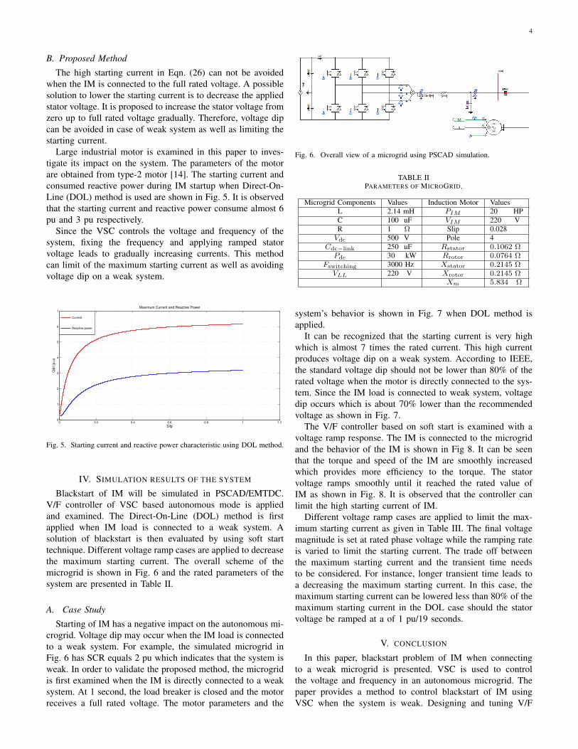
Large industrial motor is examined in this paper to inves-tigate its impact on the system. The parameters of the motorare obtained from type-2 motor [14]. The starting current andconsumed reactive power during IM startup when Direct-On-Line (DOL) method is used are shown in Fig. 5. It is observedthat the starting current and reactive power consume almost 6pu and 3 pu respectively.
Since the VSC controls the voltage and frequency of thesystem, fixing the frequency and applying ramped statorvoltage leads to gradually increasing currents. This methodcan limit of the maximum starting current as well as avoidingvoltage dip on a weak system.
0 0.2 0.4 0.6 0.8 1 1.20
1
2
3
4
5
6
7
Maximum Current and Reactive Power
Q&
I (p
.u)
Slip
Current
Reactive power
Fig. 5. Starting current and reactive power characteristic using DOL method.
IV. SIMULATION RESULTS OF THE SYSTEM
Blackstart of IM will be simulated in PSCAD/EMTDC.V/F controller of VSC based autonomous mode is appliedand examined. The Direct-On-Line (DOL) method is firstapplied when IM load is connected to a weak system. Asolution of blackstart is then evaluated by using soft starttechnique. Different voltage ramp cases are applied to decreasethe maximum starting current. The overall scheme of themicrogrid is shown in Fig. 6 and the rated parameters of thesystem are presented in Table II.
A. Case Study
Starting of IM has a negative impact on the autonomous mi-crogrid. Voltage dip may occur when the IM load is connectedto a weak system. For example, the simulated microgrid inFig. 6 has SCR equals 2 pu which indicates that the system isweak. In order to validate the proposed method, the microgridis first examined when the IM is directly connected to a weaksystem. At 1 second, the load breaker is closed and the motorreceives a full rated voltage. The motor parameters and the
Fig. 6. Overall view of a microgrid using PSCAD simulation.
TABLE IIPARAMETERS OF MICROGRID.
Microgrid Components Values Induction Motor ValuesL 2.14 mH PIM 20 HPC 100 uF VIM 220 VR 1 Ω Slip 0.028Vdc 500 V Pole 4
Cdc−link 250 uF Rstator 0.1062 ΩPdc 30 kW Rrotor 0.0764 Ω
Fswitching 3000 Hz Xstator 0.2145 ΩVLL 220 V Xrotor 0.2145 Ω
Xm 5.834 Ω
system’s behavior is shown in Fig. 7 when DOL method isapplied.
It can be recognized that the starting current is very highwhich is almost 7 times the rated current. This high currentproduces voltage dip on a weak system. According to IEEE,the standard voltage dip should not be lower than 80% of therated voltage when the motor is directly connected to the sys-tem. Since the IM load is connected to weak system, voltagedip occurs which is about 70% lower than the recommendedvoltage as shown in Fig. 7.
The V/F controller based on soft start is examined with avoltage ramp response. The IM is connected to the microgridand the behavior of the IM is shown in Fig 8. It can be seenthat the torque and speed of the IM are smoothly increasedwhich provides more efficiency to the torque. The statorvoltage ramps smoothly until it reached the rated value ofIM as shown in Fig. 8. It is observed that the controller canlimit the high starting current of IM.
Different voltage ramp cases are applied to limit the max-imum starting current as given in Table III. The final voltagemagnitude is set at rated phase voltage while the ramping rateis varied to limit the starting current. The trade off betweenthe maximum starting current and the transient time needsto be considered. For instance, longer transient time leads toa decreasing the maximum starting current. In this case, themaximum starting current can be lowered less than 80% of themaximum starting current in the DOL case should the statorvoltage be ramped at a of 1 pu/19 seconds.
V. CONCLUSION
In this paper, blackstart problem of IM when connectingto a weak microgrid is presented. VSC is used to controlthe voltage and frequency in an autonomous microgrid. Thepaper provides a method to control blackstart of IM usingVSC when the system is weak. Designing and tuning V/F

5
0 2 4 6 8 10 12 14 16 18 200
0.5
1
1.5
time(sec)
Vol
tage
(p.
u)
0 2 4 6 8 10 12 14 16 18 200
5
10
time(sec)
Cur
rent
(p.
u)
0 2 4 6 8 10 12 14 16 18 20−0.5
0
0.5
1
1.5
time(sec)
Mot
or (
p.u)
Electrical Torque
Mechanical Torque
Speed
Current
Voltage
Fig. 7. Microgrid behavior using DOL. Top figure is the voltage at PCC.Middle figure is the Line current. Bottom figure is the torques and speed ofthe IM.
0 2 4 6 8 10 12 14 16 18 200
0.5
1
1.5
time(sec)
Vol
tage
(p.
u)
0 2 4 6 8 10 12 14 16 18 200
5
10
time(sec)
Cur
rent
(p.
u)
0 2 4 6 8 10 12 14 16 18 20−0.5
0
0.5
1
1.5
time(sec)
Mot
or (
p.u)
Electrical Torque
Mechanical Torque
Speed
Voltage
Current
Fig. 8. Microgrid behavior using soft start. Top figure is the voltage at PCC.Middle figure is the line current. Bottom figure is the torques and speed ofthe IM.
TABLE IIIDIFFERENT CASES OF VOLTAGE RAMP.
Voltage Ramp Tsettling Imax Imax % Tmax
1 5 sec 7.0 p.u 100 % 0.50 p.u2 9 sec 6.7 p.u 95 % 0.45 p.u3 13 sec 6.1 p.u 87 % 0.35 p.u4 19 sec 5.5 p.u 78 % 0.25 p.u
controller of VSC are also provided. Voltage dip is occurredin weak systems and soft start method can solve this issue.This technique can limit the starting current as well.
Simulation results by PSCAD confirm the effectiveness ofthe soft start method to mitigate the blackstart issues related tohigh starting current and reactive power. It can be seen clearlythat the controller can decrease the maximum starting current.
REFERENCES
[1] J. Carrasco, L. Franquelo, J. Bialasiewicz, E. Galvan, R. Guisado,M. Prats, J. Leon, and N. Moreno-Alfonso, “Power-electronic systemsfor the grid integration of renewable energy sources: A survey,” Indus-trial Electronics, IEEE Transactions on, vol. 53, no. 4, pp. 1002–1016,June 2006.
[2] N. Flourentzou, V. Agelidis, and G. Demetriades, “Vsc-based hvdcpower transmission systems: An overview,” Power Electronics, IEEETransactions on, vol. 24, no. 3, pp. 592–602, March 2009.
[3] R. Lasseter, “Microgrids,” in Power Engineering Society Winter Meeting,2002. IEEE, vol. 1, 2002, pp. 305–308 vol.1.
[4] “Ieee recommended practice for industrial and commercial power sys-tems analysis (brown book),” IEEE Std 399-1997, pp. 1–488, Aug 1998.
[5] J. Larabee, B. Pellegrino, and B. Flick, “Induction motor startingmethods and issues,” in Petroleum and Chemical Industry Conference,2005. Industry Applications Society 52nd Annual, Sept 2005, pp. 217–222.
[6] A. Williams and M. Griffith, “Evaluating the effects of motor starting onindustrial and commercial power systems,” Industry Applications, IEEETransactions on, vol. IA-14, no. 4, pp. 292–305, July 1978.
[7] J. Rodriguez, E. Pena, P. Larrea, H. Duarte, and A. Rodriguez, “Dynamicperformance of a statcom under grid disturbances for two differentlinear controllers,” in IECON 2012 - 38th Annual Conference on IEEEIndustrial Electronics Society, Oct 2012, pp. 356–361.
[8] L. Zhang, L. Harnefors, and H.-P. Nee, “Power-synchronization controlof grid-connected voltage-source converters,” Power Systems, IEEETransactions on, vol. 25, no. 2, pp. 809–820, May 2010.
[9] M. Kazmierkowski and L. Malesani, “Current control techniques forthree-phase voltage-source pwm converters: a survey,” Industrial Elec-tronics, IEEE Transactions on, vol. 45, no. 5, pp. 691–703, Oct 1998.
[10] A. Yazdani and R. Iravani, Voltage-sourced converters in power systems:modeling, control, and applications. John Wiley & Sons, 2010.
[11] C. Bajracharya, M. Molinas, J. A. Suul, T. M. Undeland et al., “Under-standing of tuning techniques of converter controllers for vsc-hvdc,” inNordic Workshop on Power and Industrial Electronics (NORPIE/2008),June 9-11, 2008, Espoo, Finland. Helsinki University of Technology,2008.
[12] P. C. Sen, Principles of electric machines and power electronics. JohnWiley & Sons, 2007.
[13] “Ieee guide for planning dc links terminating at ac locations having lowshort-circuit capacities,” IEEE Std 1204-1997, pp. i–, 1997.
[14] W. Price, C. Taylor, and G. Rogers, “Standard load models for powerflow and dynamic performance simulation,” IEEE Transactions on powersystems, vol. 10, no. CONF-940702–, 1995.