Embed Size (px)
Citation preview

Blinding of Feeder Protection caused by Distributed Generation in Distribution Network
KARI MÄKI, SAMI REPO, PERTTI JÄRVENTAUSTA
Institute of Power Engineering Tampere University of Technology P.O.Box 692, FIN-33101 Tampere
FINLAND
Abstract: - This paper considers the effect of distributed generation on protection of distribution network. A special emphasis is on blinding problem, which may occur in the distribution network in the presence of distributed generation. The blinding phenomenon is introduced, discussed in detail and some simulation results are presented for an actual installation case. The theoretical background of blinding and calculation of the effect is also presented. The studies presented are made from the network operator’s point of view. Key-Words: - Distributed generation, protection, relay, blinding, network planning 1 Introduction Distributed generation (DG) applied on the distribution level is a common concern among distribution companies nowadays. DG is usually associated with wind power, photovoltaics and certain other environmentally friendly forms of energy. While these are some of the most typical forms of DG, the term itself, however, means simply generation that is not centrally dispatched and is typically small-scale enough to be connected straight to the distribution network. Also the liberalized energy market is steering the interest towards smaller and more modular generation units. DG has certain positive effects. It can support the voltage in the network, especially when located far from the feeding primary substation. In some cases it can even be used to avoid or to postpone network investments. In many cases it can decrease losses in the distribution level when located near to the loads. Despite these positive facts listed, DG can cause some problems in the distribution network. Two major problems consider the voltage levels and the operation of protection during fault situations. This paper concentrates on protection issues, especially on the blinding problem. Evaluating the network effects of a new DG unit requires accurate studies. Generally, the case must be modeled very comprehensively in order to make right conclusions. These studies become easily very complex requiring iterative loops and many values to be checked. Additionally, the rapid development
of the amount of DG installed makes the network planning and controlling more complicated. 2 Protection philosophy at the
distribution level Typically, the protection of distribution network is based on the assumption of unidirectional flow of fault currents. More generally, this assumption of unidirectional power flow is applied in most of the operations at the distribution level. The short-circuit protection is in this case relatively straightforward to implement with overcurrent relays coordinated to achieve selectivity and comprehensiveness of operation. The current flowing ‘down’ to the fault point is measured at certain points and tripped where needed in order to disconnect only the smallest part of the network required. For instance, inverse-time relays with operation time varying according to the fault current or definite-time relays with pre-set operation times can be used. [1,2] Integrating DG at distribution level may change the essential basis of network protection and operation presented above. In a network with DG unit(s) installed, the fault currents may also have an ‘upward’ direction. Same applies to the power flow. The DG unit can thus feed fault current also to faults located on other feeders of the same substation or even at the higher voltage levels. Practically all amounts of fault current measured in the network will change to some extent due to the presence of DG. The directions of fault currents may also change. The varying directions and currents
Proceedings of the 5th WSEAS Int. Conf. on Power Systems and Electromagnetic Compatibility, Corfu, Greece, August 23-25, 2005 (pp377-382)

complicate the using of traditional protection based on the assumption of unidirectionality. [2] These facts presented may thus cause some problems with the operation of protection. Certain studies are thereby needed. For instance, the following issues need to be checked:
• Thermal limits of components • Operation of DG-feeder protection in
different types of faults • Operation of DG unit protection during
reclosings • Fault current contribution of the DG unit
during faults elsewhere in the network • Operation of protection during voltage sags
and other disturbances 3 The blinding phenomenon Among other electrical factors, certain typical protection problems can be defined which are possible in the presence of DG. Three typical problems can be defined:
• Protection blinding • Sympathetic tripping • Failed reclosing
This paper focuses on blinding, which is relatively common protection problem on distribution level but yet quite unknown phenomenon. The problem is first introduced, then some theoretical background is explained, and finally results for studies in an actual network are presented. Sympathetic tripping and reclosing problem have been earlier discussed for instance in [3, 4]. The overall complexity of protecting and controlling the distribution system with DG has been considered for instance in [5]. 3.1 Blinding at distribution level Protection blinding is a critical issue as it may decrease the range seen by the relay. This may happen when the DG unit and the substation are feeding the fault in parallel. Due to the short circuit impedances the current flowing through the feeder relay decreases [6]. The theoretical background has been presented in the following chapter. Generally, overall fault levels always increase due to the presence of DG, but the current measured by the relay is the value that dictates the operation of the feeder protection. Hence the decrease of fault current caused by the DG unit should always be taken into account. Exactly similar problems can be expected in fuse protection of a low voltage network
[7]. Simple example situation has been presented in figure 1. Figure 2 presents simulated relay currents for the case presented in figure 1. Initial values without DG connected as well as values with DG applying synchronous generator or induction generator are presented. Also an inverter based unit can result in blinding although the effective fault current contribution is relatively low [7].
Fig. 1: Typical situation in which protection blinding is possible.
Feeder fault current in different casesInitial situation
-400
-300
-200
-100
0
100
200
300
400
Cur
rent
[A]
With synchronous generator installed
-400
-300
-200
-100
0
100
200
300
400
Cur
rent
[A]
With induction generator installed
-400
-300
-200
-100
0
100
200
300
400
0,9 0,95 1 1,05 1,1 1,15 1,2 1,25 1,3 1,35 1,4Time [s]
Cur
rent
[A]
Fig. 2: Simulated fault currents showing the blinding effect. Cases without DG, with synchronous generator and with induction generator are presented.
Proceedings of the 5th WSEAS Int. Conf. on Power Systems and Electromagnetic Compatibility, Corfu, Greece, August 23-25, 2005 (pp377-382)

Due to the blinding, the relay protection may become non-operational in certain parts of the network, typically in the tail parts of the feeder including DG units. In this sense, the most problematic fault types are two-phase faults and faults with high impedances. Especially with definite-time relays blinding is an issue as the operation may become totally blocked when the lower tripping level is no more exceeded. In proportion, with inverse-time relays the blinding may result in delay in the operation of protection, which can further lead to problems with thermal limits of components and lines. Similarly, if the blinding blocks the operation totally, but the DG unit is disconnected by its own protection (hence re-enabling the operation of feeder protection), a delay of DG unit protection operation time will appear in the operation of feeder protection. Most evident solution for such problems is applying new relay operation characteristics with lower tripping limits. In many cases this is possible and is thus a simple and efficient means to avoid blinding related problems. However, certain issues may arise when lowering the tripping limits:
• Operation during a fault on adjacent feeder • Extreme load/generation –combinations • Starting currents of DG units and other
rotating devices Especially the possibility of conflicting with the settings required by the sympathetic tripping problem during a fault on an adjacent feeder is to be considered. This has been discussed more detailed in [3,4]. Other solutions include for instance defining strict enough constraints for the operation of DG unit protection. However, the delay of operation mentioned above can not be totally avoided in the cases in which the blinding is possible. To prevent the blinding completely, network reinforcements or modifications in the type of DG unit are possible. Network reinforcements easily ruin the cost-effectiveness of DG as the whole idea is based on installing small units without significant additional costs. The type of DG unit and thus its electrical values can usually be influenced by the network operator during the planning period, but not later. 3.2 Theoretical background for the blinding
phenomenon Reasoning for blinding can be found using normal fault current calculation applying thevenin’s
impedances. First of all, let us assume the following, very simplified situation.
Fig. 3: Simple network presenting the network impedances during a fault in the presence of DG. In figure 3, a point called “common feed point” is defined. This has been made to simplify the presentation of blinding. Common feed point (CFP) is here defined as the point closest to the fault, which is yet fed in parallel by the DG unit and the feeding network. Thus CFP is not a fixed point; it can be found in various locations for different fault situations. For faults on the same branch, the CFP is, however, common. In some cases the fault can be located directly in the CFP, meaning the Zfault_b equal to zero. Common feed point is important because the intensity of blinding is dictated by the ratio of impedances between the CFP and other parts of the network as shown later. As a first case, if the DG unit located on the left in figure 3 is ignored, the fault current Ifeeder for a symmetrical short-circuit fault can be calculated as follows [1] :
bfaultnet
faultfeeder ZZ
UI
_+= (1)
Ufault is the pre-fault voltage of the fault point. Other variables are impedances as marked in figure 3. Zfault_b means here the total branch impedance between the common feed point and the fault including also the fault impedance. If we now connect the DG unit to the network as shown in figure 3 and mark the impedance of the DG unit connection line and the unit itself as Zgen, we can calculate the thevenin impedance for the
Proceedings of the 5th WSEAS Int. Conf. on Power Systems and Electromagnetic Compatibility, Corfu, Greece, August 23-25, 2005 (pp377-382)

parallel connection of feeding network and the DG unit simply as follows:
⎟⎟⎠
⎞⎜⎜⎝
⎛
++=
netgen
netgenbfaultth ZZ
ZZZZ _ (2)
Further, calculating the total fault current with reduced parallel impedance and dividing the fault current for feeder branch gives: (3) (4) (5), which can be further simplified to:
fault
netgen
netbfaultbfault
feeder UZ
ZZZ
ZI
⎟⎟⎟⎟⎟
⎠
⎞
⎜⎜⎜⎜⎜
⎝
⎛
++=
__
1 (6),
which shows that with a faulted branch impedance equal to zero, the current measured at the relay will remain the same as without the DG unit installed. It is important to notice that the faulted branch impedance Zfault_b here includes also the branch between the common feed point and the fault. Thereby Zfault_b equal or near to zero would be possible mostly on main line between the DG unit and the substation with a theoretical fault with no impedance. Thus blinding practically always occurs during the fault to some extent, but the intensity of the phenomenon is dictated by the location of fault, in other words the impedance Zfault_b and its relation to the other impedances. Similarly, it’s easy to see that a situation with DG unit temporarily disconnected also results in the initial form of equation (1). This can be seen as the open breaker at the DG connection point can be presented as infinite Zgen. Thus the disconnected DG unit has no effect on protection, which is evident.
Assuming Zfault_b as well as Zgen greater than zero and Zgen remaining in finite limits shows easily:
bfaultnet
fault
netgen
netbfaultbfault
fault
ZZU
ZZ
ZZZ
U
___
+<
++ (7),
which in other words means:
DGwithoutfeederDGwithfeeder II _,_, < (8) This is called protection blinding. The pre-fault voltage Ufault may also be increased due to the DG unit depending on unit’s voltage control system. However, the effect of short-circuit impedances is usually greater and the current measured by the relay therefore decreases. This aspect has been discussed later using the example case. From equations 1 and 6 it can be seen that the network reinforcements to decrease the impedances Znet and Zfault_b naturally result in higher fault currents at the relay regardless of the state of DG unit. Thereby the blinding problem could be avoided by applying reinforcements between the substation and the CFP, or similarly between the CFP and the worst-case fault location. However, reinforcing the branch that connects the DG unit to the CFP results in a more severe blinding problem. This is also evident, as the contribution of DG unit increases due to the stronger connection to the CFP. Unfortunately other aspects such as voltage or power flow often require reinforcing the network particularly in the vicinity of the DG unit. 3.3 Blinding phenomenon studied in an
example case In the following a simple example case is studied applying the equations presented above. The overall network form is similar to the one presented earlier in figure 3. The case comprises of a medium-voltage distribution network at the Finnish coast and a small wind park with four synchronous generators to be connected into the network. The network is relatively weak overhead network with some sea cable connections, showing thereby the blinding effects quite strongly. The feeder 1 studied is equipped with definite-time overcurrent relays. The distance between the feeding substation and the wind park is about 22 kilometers. The distance from the CFP to the tail of the feeder is more than 30 kilometers. Actual network data is used in the example network. The network form is presented in
faultfault
feeder ZZZ ⎟⎠
⎜⎝ ++ )_ netgennetgenb
gen
netgen
netgenbfault
fault
netgen
gen
thnetgen
gen
UZZ
Z
ZZZ
UZ
ZU
ZZZ
⎟⎞
⎜⎛
=
⎟⎟
⎟⎟
⎠
⎞
⎜⎜⎜⎜⎜
⎝
⎛
++⎠
⎞
⎝
⎛
⎠
⎞⎜⎜⎝
⎛
⎠
⎞
⎝
⎛
+
(
_
feeder ZZZZI ⎟⎟
⎟⎜⎜
+=
faultfeederI ⎟⎟⎟
⎟⎜⎜=
I
Proceedings of the 5th WSEAS Int. Conf. on Power Systems and Electromagnetic Compatibility, Corfu, Greece, August 23-25, 2005 (pp377-382)
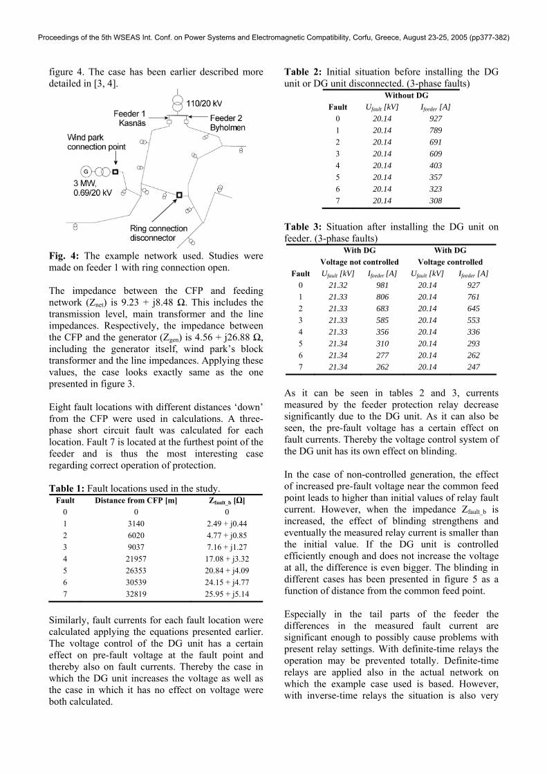
figure 4. The case has been earlier described more detailed in [3, 4].
Fig. 4: The example network used. Studies were made on feeder 1 with ring connection open. The impedance between the CFP and feeding network (Znet) is 9.23 + j8.48 Ω. This includes the transmission level, main transformer and the line impedances. Respectively, the impedance between the CFP and the generator (Zgen) is 4.56 + j26.88 Ω, including the generator itself, wind park’s block transformer and the line impedances. Applying these values, the case looks exactly same as the one presented in figure 3. Eight fault locations with different distances ‘down’ from the CFP were used in calculations. A three-phase short circuit fault was calculated for each location. Fault 7 is located at the furthest point of the feeder and is thus the most interesting case regarding correct operation of protection. Table 1: Fault locations used in the study.
Fault Distance from CFP [m] Zfault_b [Ω] 0 0 0 1 3140 2.49 + j0.44 2 6020 4.77 + j0.85 3 9037 7.16 + j1.27 4 21957 17.08 + j3.32 5 26353 20.84 + j4.09 6 30539 24.15 + j4.77 7 32819 25.95 + j5.14
Similarly, fault currents for each fault location were calculated applying the equations presented earlier. The voltage control of the DG unit has a certain effect on pre-fault voltage at the fault point and thereby also on fault currents. Thereby the case in which the DG unit increases the voltage as well as the case in which it has no effect on voltage were both calculated.
Table 2: Initial situation before installing the DG unit or DG unit disconnected. (3-phase faults)
Without DG Fault Ufault [kV] Ifeeder [A]
0 20.14 927 1 20.14 789 2 20.14 691 3 20.14 609 4 20.14 403 5 20.14 357 6 20.14 323 7 20.14 308
Table 3: Situation after installing the DG unit on feeder. (3-phase faults)
With DG With DG Voltage not controlled Voltage controlled Fault Ufault [kV] Ifeeder [A] Ufault [kV] Ifeeder [A]
0 21.32 981 20.14 927 1 21.33 806 20.14 761 2 21.33 683 20.14 645 3 21.33 585 20.14 553 4 21.33 356 20.14 336 5 21.34 310 20.14 293 6 21.34 277 20.14 262 7 21.34 262 20.14 247
As it can be seen in tables 2 and 3, currents measured by the feeder protection relay decrease significantly due to the DG unit. As it can also be seen, the pre-fault voltage has a certain effect on fault currents. Thereby the voltage control system of the DG unit has its own effect on blinding. In the case of non-controlled generation, the effect of increased pre-fault voltage near the common feed point leads to higher than initial values of relay fault current. However, when the impedance Zfault_b is increased, the effect of blinding strengthens and eventually the measured relay current is smaller than the initial value. If the DG unit is controlled efficiently enough and does not increase the voltage at all, the difference is even bigger. The blinding in different cases has been presented in figure 5 as a function of distance from the common feed point. Especially in the tail parts of the feeder the differences in the measured fault current are significant enough to possibly cause problems with present relay settings. With definite-time relays the operation may be prevented totally. Definite-time relays are applied also in the actual network on which the example case used is based. However, with inverse-time relays the situation is also very
Proceedings of the 5th WSEAS Int. Conf. on Power Systems and Electromagnetic Compatibility, Corfu, Greece, August 23-25, 2005 (pp377-382)

problematic, as the relay operation is delayed usually quite much on the lowest current levels. On the other hand, the overall fault current flowing to the fault point increases. In other words, the fault current is actually increased but the tripping is delayed. This can cause problems with the thermal limits of lines and components.
200
300
400
500
600
700
800
900
1000
0 5000 10000 15000 20000 25000 30000 35000
Distance from CFP [m]
Ifeed
er [A
]
Without DGWith DG, voltage not controlledWith DG, voltage controlled
Fig. 5: Relay currents presented as a function of distance from the common feed point. The fault point 7 has the longest electrical distance from the relay and is thus the point in which the operation of protection needs to be especially studied. Calculating for a 2-phase fault, a fault current of 266 A was to be expected. Due to the DG unit to be installed and the blinding problem these currents will decrease. Depending on the voltage control of the DG unit, the new fault current sensed by the relay would be 226 A or 213 A. In the worst case, the difference is more than 50 A and might interfere with the relay protection. 4 Conclusion As described in the article, protection blinding can become a serious problem in certain installation cases. When new DG units are installed to the network, blinding of relays always increases to some extent. However, possible problems occur when the effect becomes too violent. The rate of the effect depends on short circuit impedances ratio between:
• Feeding network and common feed point • DG unit and common feed point • Common feed point and fault
Similarly, fault levels increase always to a certain extent, when new DG units are installed.
Blinding may result in total failure of operation of protection or it may cause some delay to the operation of protection. Combined with increased fault levels and multiple fault current infeeds, such malfunctions can easily lead to adequate thermal limits of components and lines. Thereby the effects of planned DG units should be studied comprehensively enough in advance to find out modifications required. In a more extensive network planning perspective blinding must be considered simultaneously with other protection related issues. Especially the operation during a fault on an adjacent feeder (possibility of sympathetic tripping) is usually more or less inconsistent with blinding problems [4]. The operation of DG unit protection has an essential effect on blinding as well. On the other hand, where blinding occurs, feeder tripping can always be at least delayed by the operation time of DG unit protection. References: [1] E. Lakervi, E.J. Holmes, Electricity distribution network design, IEE, 1998, 325 p. [2] S.K. Salman, I.M. Rida, Investigating the Impact of Embedded Generation on Relay Settings of Utilities’ Electrical Feeders, IEEE Transactions on Power Delivery, Vol.16, No.2, 2001, pp.246
-251 [3] K. Mäki, P. Järventausta, S. Repo, Protection
issues in planning of distribution network including distributed generation, CIGRE Symposium: Power Systems with Dispersed Generation, 2005, pp. 1P-05
[4] K. Mäki, S. Repo, P. Järventausta, Effect of wind power based distributed generation on protection of distribution network, Developments in Power System Protection, 2004, pp. 327-330
[5] N. Hadjsaid, J-F. Canard, F. Dumas, Dispersed generation increases the complexity of controlling, protecting and maintaining the distribution systems, IEEE Computer Applications in Power, April 1999, pp.23-28
[6] R.C. Dugan, T.E. McDermott, Operation Conflicts for Distributed Generation on Distribution Systems, IEE Rural Electric Power Conference 2001, pp. A3-1 – A3-6
[7] L. Kumpulainen, K. Kauhaniemi, P. Verho, O. Vähämäki, New requirements for system protection caused by distributed generation, CIRED 18th International Conference on Electricity Distribution, 2005
Proceedings of the 5th WSEAS Int. Conf. on Power Systems and Electromagnetic Compatibility, Corfu, Greece, August 23-25, 2005 (pp377-382)