Embed Size (px)
Citation preview
Authors:Student1 Student2
Blobo Clone – Angry Birds Toy Upgrade
Schedule of the project and log of work done
DOCUMENT INFORMATION
Subject:
Authors: Student1, Student2
Keywords:
Comments:
Creation date: 10 December 2012
Revision date: 02/21/13
Print date: 02/21/13
PROJECT INFORMATION
Course name: Embedded Systems Project
Assistent: Assistant
Document status: [ ] Draft
[x] Proposal
[ ] Inspected & approved
Revision history:
Page 1 of 16
Authors:Student1 Student2
Content
SCHEDULE ................................................................................................................................................... 3
Project management ................................................................................................................................... 3
Stories and tasks ......................................................................................................................................... 4
Story level time schedule ............................................................................................................................ 9
LOG ........................................................................................................................................................... 10
Daily hour log ............................................................................................................................................ 10
Story level time log ................................................................................................................................... 14
SUMMARY ................................................................................................................................................. 15
Page 2 of 16
Authors:Student1 Student2
1. Schedule
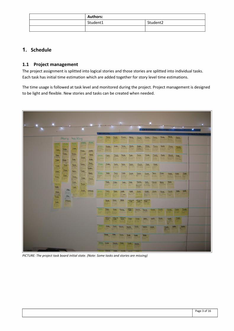
1.1 Project managementThe project assignment is splitted into logical stories and those stories are splitted into individual tasks. Each task has initial time estimation which are added together for story level time estimations.
The time usage is followed at task level and monitored during the project. Project management is designed to be light and flexible. New stories and tasks can be created when needed.
PICTURE: The project task board initial state. (Note: Some tasks and stories are missing)
Page 3 of 16
Authors:Student1 Student2
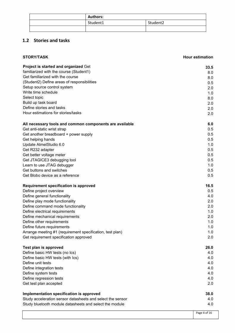
1.2 Stories and tasks
STORY/TASK Hour estimation
33.58.08.00.52.01.08.02.02.0
Project is started and organized Get familiarized with the course (Student1) Get familiarized with the course (Student2) Define areas of responsibilities Setup source control systemWrite time scheduleSelect topicBuild up task boardDefine stories and tasksHour estimations for stories/tasks 2.0
All necessary tools and common components are available 6.0Get anti-static wrist strap 0.5Get another breadboard + power supply 0.5Get helping hands 0.5Update AtmelStudio 6.0 1.0Get R232 adapter 0.5Get better voltage meter 0.5Get JTAGICE3 debugging tool 0.5Learn to use JTAG debugger 1.0Get buttons and switches 0.5Get Blobo device as a reference 0.5
Requirement specification is approved 16.5Define project overview 0.5Define general functionality 4.0Define play mode functionality 2.0Define command mode functionality 2.0Define electrical requirements 1.0Define mechanical requirements 2.0Define other requirements 1.0Define future requirements 1.0Arrange meeting #1 (requirement specification, test plan) 1.0Get requirement specification approved 2.0
Test plan is approved 26.0Define basic HW tests (no Ics) 4.0Define basic HW tests (with Ics) 4.0Define unit tests 4.0Define integration tests 4.0Define system tests 4.0Define regression tests 4.0Get test plan accepted 2.0
Implementation specification is approved 38.0Study acceleration sensor datasheets and select the sensor 4.0Study bluetooth module datasheets and select the module 4.0
Page 4 of 16
Authors:Student1 Student2
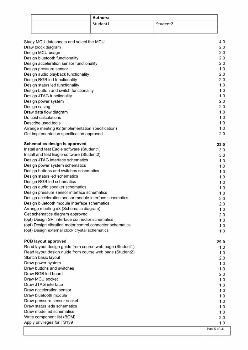
Study MCU datasheets and select the MCU 4.0Draw block diagram 2.0Design MCU usage 2.0Design bluetooth functionality 2.0Design acceleration sensor functionality 2.0Design pressure sensor 1.0Design audio playback functionality 2.0Design RGB led functionality 2.0Design status led functionality 1.0Design button and switch functionality 1.0Design JTAG functionality 1.0Design power system 2.0Design casing 2.0Draw data flow diagram 1.0Do cost calculations 1.0Describe used tools 1.0Arrange meeting #2 (implementation specification) 1.0Get implementation specification approved 2.0
23.03.03.01.01.01.01.01.01.01.02.02.01.02.01.01.0
Schematics design is approvedInstall and test Eagle software (Student1)Install and test Eagle software (Student2)Design JTAG interface schematicsDesign power system schematicsDesign buttons and switches schematicsDesign status led schematicsDesign RGB led schematicsDesign audio speaker schematicsDesign pressure sensor interface schematicsDesign acceleration sensor module interface schematics Design bluetooth module interface schematicsArrange meeting #3 (Schematic diagram)Get schematics diagram approved(opt) Design SPI interface connector schematics(opt) Design vibration motor control connector schematics (opt) Design external clock crystal schematics 1.0
29.01.01.02.01.01.02.01.01.01.01.01.01.01.02.0
PCB layout approvedRead layout design guide from course web page (Student1) Read layout design guide from course web page (Student2) Sketch basic layoutDraw power systemDraw buttons and switchesDraw RGB led boardDraw MCU socketDraw JTAG interfaceDraw acceleration sensor Draw bluetooth moduleDraw pressure sensor socketDraw status leds schematicsDraw mode led schematicsWrite component list (BOM)Apply privileges for TS139 1.0
Page 5 of 16
Authors:Student1 Student2
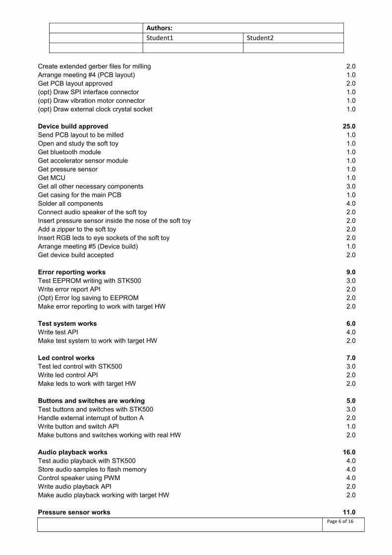
Create extended gerber files for milling 2.0Arrange meeting #4 (PCB layout) 1.0Get PCB layout approved 2.0(opt) Draw SPI interface connector 1.0(opt) Draw vibration motor connector 1.0(opt) Draw external clock crystal socket 1.0
Device build approved 25.0Send PCB layout to be milled 1.0Open and study the soft toy 1.0Get bluetooth module 1.0Get accelerator sensor module 1.0Get pressure sensor 1.0Get MCU 1.0Get all other necessary components 3.0Get casing for the main PCB 1.0Solder all components 4.0Connect audio speaker of the soft toy 2.0Insert pressure sensor inside the nose of the soft toy 2.0Add a zipper to the soft toy 2.0Insert RGB leds to eye sockets of the soft toy 2.0Arrange meeting #5 (Device build) 1.0Get device build accepted 2.0
Error reporting works 9.0Test EEPROM writing with STK500 3.0Write error report API 2.0(Opt) Error log saving to EEPROM 2.0Make error reporting to work with target HW 2.0
Test system works 6.0Write test API 4.0Make test system to work with target HW 2.0
Led control works 7.0Test led control with STK500 3.0Write led control API 2.0Make leds to work with target HW 2.0
Buttons and switches are working 5.0Test buttons and switches with STK500 3.0Handle external interrupt of button A 2.0Write button and switch API 1.0Make buttons and switches working with real HW 2.0
Audio playback works 16.0Test audio playback with STK500 4.0Store audio samples to flash memory 4.0Control speaker using PWM 4.0Write audio playback API 2.0Make audio playback working with target HW 2.0
Pressure sensor works 11.0Page 6 of 16
Authors:Student1 Student2
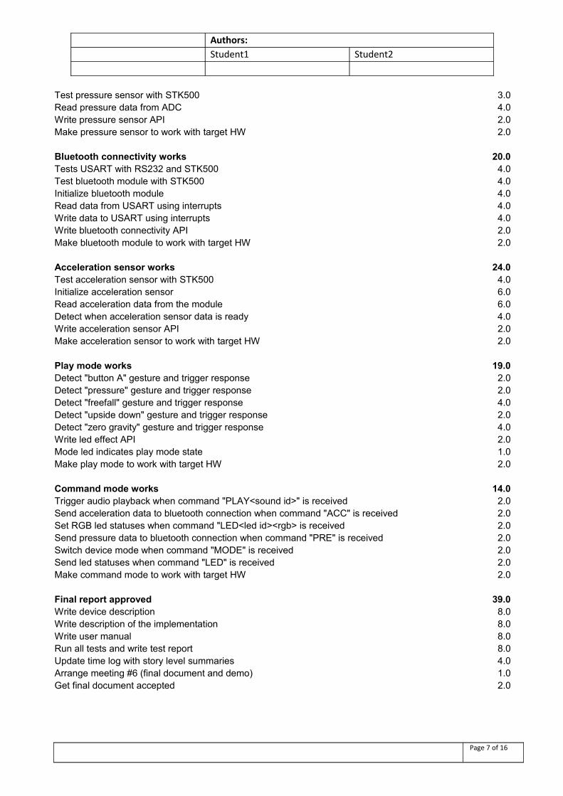
Test pressure sensor with STK500 3.0Read pressure data from ADC 4.0Write pressure sensor API 2.0Make pressure sensor to work with target HW 2.0
Bluetooth connectivity works 20.0Tests USART with RS232 and STK500 4.0Test bluetooth module with STK500 4.0Initialize bluetooth module 4.0Read data from USART using interrupts 4.0Write data to USART using interrupts 4.0Write bluetooth connectivity API 2.0Make bluetooth module to work with target HW 2.0
Acceleration sensor works 24.0Test acceleration sensor with STK500 4.0Initialize acceleration sensor 6.0Read acceleration data from the module 6.0Detect when acceleration sensor data is ready 4.0Write acceleration sensor API 2.0Make acceleration sensor to work with target HW 2.0
Play mode works 19.0Detect "button A" gesture and trigger response 2.0Detect "pressure" gesture and trigger response 2.0Detect "freefall" gesture and trigger response 4.0Detect "upside down" gesture and trigger response 2.0Detect "zero gravity" gesture and trigger response 4.0Write led effect API 2.0Mode led indicates play mode state 1.0Make play mode to work with target HW 2.0
Command mode works 14.0Trigger audio playback when command "PLAY<sound id>" is received 2.0Send acceleration data to bluetooth connection when command "ACC" is received 2.0Set RGB led statuses when command "LED<led id><rgb> is received 2.0Send pressure data to bluetooth connection when command "PRE" is received 2.0Switch device mode when command "MODE" is received 2.0Send led statuses when command "LED" is received 2.0Make command mode to work with target HW 2.0
Final report approved 39.0Write device description 8.0Write description of the implementation 8.0Write user manual 8.0Run all tests and write test report 8.0Update time log with story level summaries 4.0Arrange meeting #6 (final document and demo) 1.0Get final document accepted 2.0
Page 7 of 16
Authors:Student1 Student2
Totally hour estimation is 364 hours. The hour realization is tracked by story level and compared to initial estimations at the end of the project. Realization is also tracked during the project to keep progress estimations up-to-date.
Page 8 of 16
Authors:Student1 Student2
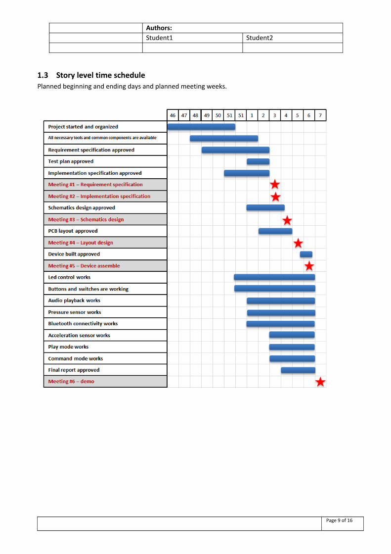
1.3 Story level time schedulePlanned beginning and ending days and planned meeting weeks.
Page 9 of 16
Authors:Student1 Student2
2. Log
2.1 Daily hour log
The hour log was kept separate from the task and story based time log so there are differences between these two logs. The accuracy of the time logs is estimated to be around 10-20% but they gives a good overall view about time usage of this project.
3.10.2012:
MK: 1.0h Initial lecture
MP: 1.0h Initial lecture
1.11.2012-31.11-2012:
MK: 20.0h Studying Atmega MCU:s and selecting the topic.
16.12.2012:
MP: 2.0h Reading course material
18.12.2012:
MK: 2.0h Reading atmega32 datasheets
19.12.2012:
MK: 6.0h Writing requirement specification, planning time table
20.12.2012:
MK: 8.0h Writing requirement specification
21.12.2012:
MK: 3.0h Exploring set of new components and development tools
22.12.2012:
MK: 1.0h Finding components for sensors and bluetooth
23.12.2012:
MK: 3.0h Finding components for sensors and bluetooth
27.12.2012:
Page 10 of 16
Authors:Student1 Student2
MK: 3.0h Studying component datasheets
28.12.2012:
MK: 3.0h Studying component datasheets
29.12.2012:
MK: 3.0h Writing requirement specification and design specification, studying component datasheets
30.12.2012:
MK: 3.0h Writing requirement specification and design specification, studying component datasheets
31.12.2012:
MK: 5.0h Writing requirement specification and design specification, studying component datasheets
1.1.2013:
MK: 6.0h Writing requirement specification and design specification, studying component datasheets.
2.1.2013:
MK: 8.0h Writing implementation specification.
MP: 1.0h Reading course material
3.1.2013:
MK: 8.0h Studying datasheets, selecting components, writing implementation specification, testing voltage regulation.
MP: 2.0h Reading course material
4.1.2013:
MK: 8.0h Studying acceleration sensor and MCU datasheets, sketching PCB, testing push button with STK500
MP: 3.0h Writing test report
5.1.2013:
MK: 8.0h Studying acceleration sensor and MCU datasheets, sketching PCB
MP: 2.0h Writing test report
6.1.2013:
MK: 14.0h Testing USART with STK500
7.1.2013:
Page 11 of 16
Authors:Student1 Student2
MK: 6.0h Testing audio playback with STK500
8.1.2013:
MK: 8.0h Testing audio playback with STK 500
9.1.2013:
MK: 8.0h Building task board, task hour estimations, updating requirement specification and implementation specification, testing JTAGICE3 tool.
MP: 2.0h Testing Eagle
10.1.2013:
MK: 12.0h Writing time schedule log, building task board, testing Eagle and designing schematics
MP: 3.0h Writing test report, updating spefications document
11.1.2013:
MK: 10.0h Designing schematics
MP: 4.0h Writing test report, updating schedule log
12.1.2013:
MK: 3.0h Setting up control system
13.1.2013:
MK: 8.5h Coding basic API:s, testing PCB layout
MP: 3.0h Writing test report
14.1.2013:
MK: 10.5h Team meeting, writing tests, documentation, PCB layout designing
MP: 5.0h Team meeting, writing test report, updating spefications document
15.1.2013:
MK: 9.5h Layout design, programming
16.1.2013:
MK: 10.5h Programming
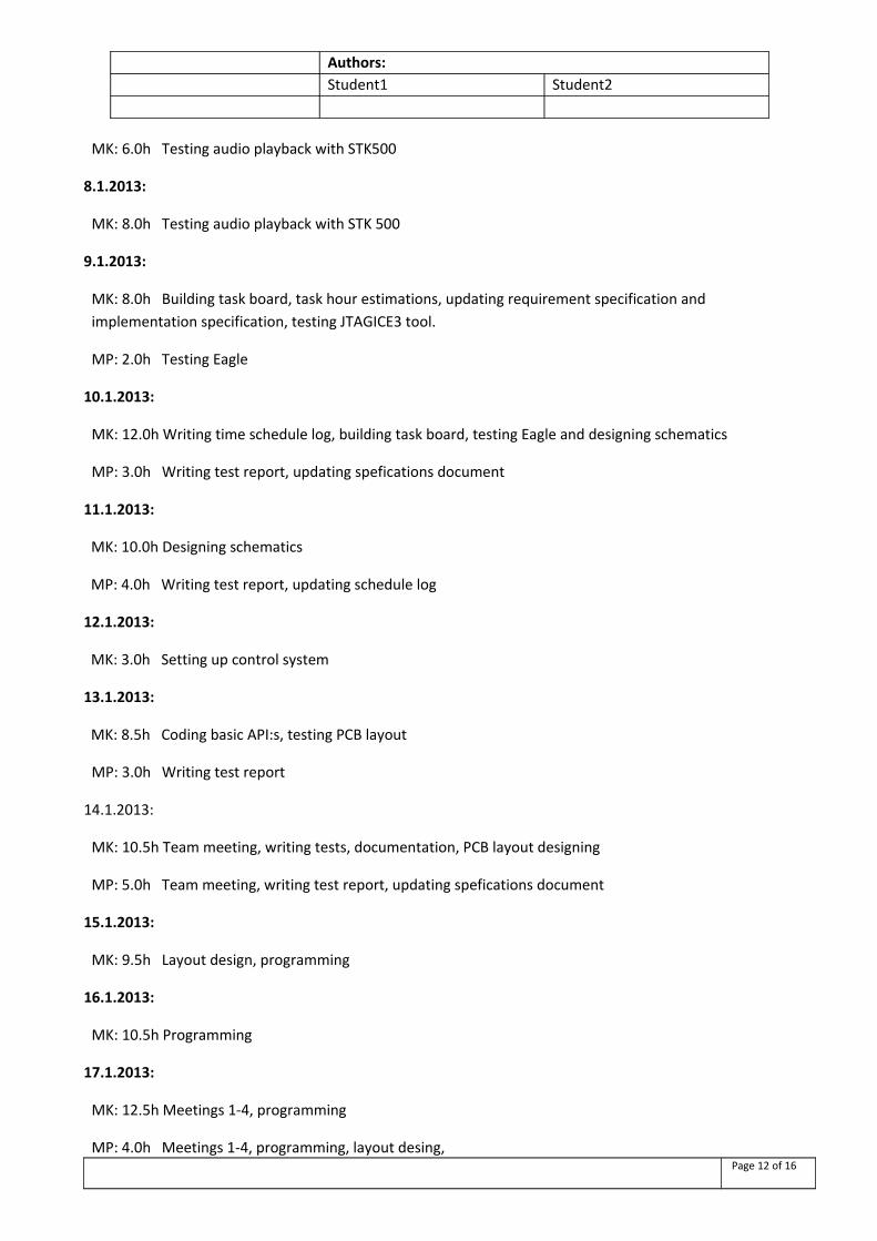
17.1.2013:
MK: 12.5h Meetings 1-4, programming
MP: 4.0h Meetings 1-4, programming, layout desing, Page 12 of 16
Authors:Student1 Student2
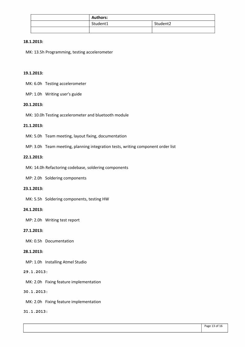
18.1.2013:
MK: 13.5h Programming, testing accelerometer
19.1.2013:
MK: 6.0h Testing accelerometer
MP: 1.0h Writing user's guide
20.1.2013:
MK: 10.0h Testing accelerometer and bluetooth module
21.1.2013:
MK: 5.0h Team meeting, layout fixing, documentation
MP: 3.0h Team meeting, planning integration tests, writing component order list
22.1.2013:
MK: 14.0h Refactoring codebase, soldering components
MP: 2.0h Soldering components
23.1.2013:
MK: 5.5h Soldering components, testing HW
24.1.2013:
MP: 2.0h Writing test report
27.1.2013:
MK: 0.5h Documentation
28.1.2013:
MP: 1.0h Installing Atmel Studio
29.1.2013:
MK: 2.0h Fixing feature implementation
30.1.2013:
MK: 2.0h Fixing feature implementation
31.1.2013:
Page 13 of 16
Authors:Student1 Student2
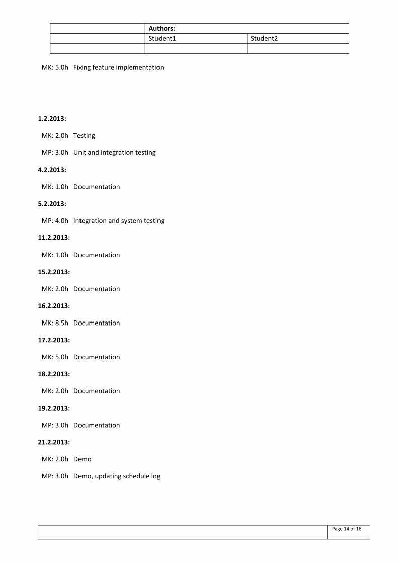
MK: 5.0h Fixing feature implementation
1.2.2013:
MK: 2.0h Testing
MP: 3.0h Unit and integration testing
4.2.2013:
MK: 1.0h Documentation
5.2.2013:
MP: 4.0h Integration and system testing
11.2.2013:
MK: 1.0h Documentation
15.2.2013:
MK: 2.0h Documentation
16.2.2013:
MK: 8.5h Documentation
17.2.2013:
MK: 5.0h Documentation
18.2.2013:
MK: 2.0h Documentation
19.2.2013:
MP: 3.0h Documentation
21.2.2013:
MK: 2.0h Demo
MP: 3.0h Demo, updating schedule log
Page 14 of 16
Authors:Student1 Student2
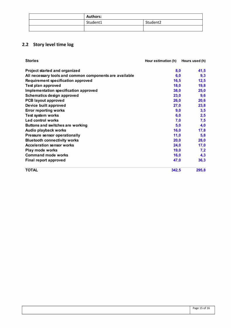
2.2 Story level time log
Page 15 of 16
Stories Hour estimation (h) Hours used (h)
Project started and organized 8,0 41,5All necessary tools and common components are available 6,0 9,3Requirement specification approved 16,5 12,5Test plan approved 18,0 19,8Implementation specification approved 38,0 25,0Schematics design approved 23,0 9,6PCB layout approved 26,0 20,6Device built approved 27,0 23,8Error reporting works 9,0 3,5Test system works 6,0 2,5Led control works 7,0 7,5Buttons and switches are working 5,0 4,0Audio playback works 16,0 17,8Pressure sensor operationally 11,0 5,8Bluetooth connectivity works 20,0 28,0Acceleration sensor works 24,0 17,0Play mode works 19,0 7,2Command mode works 16,0 4,3Final report approved 47,0 36,3
TOTAL 342,5 295,8
Authors:Student1 Student2
3. Summary
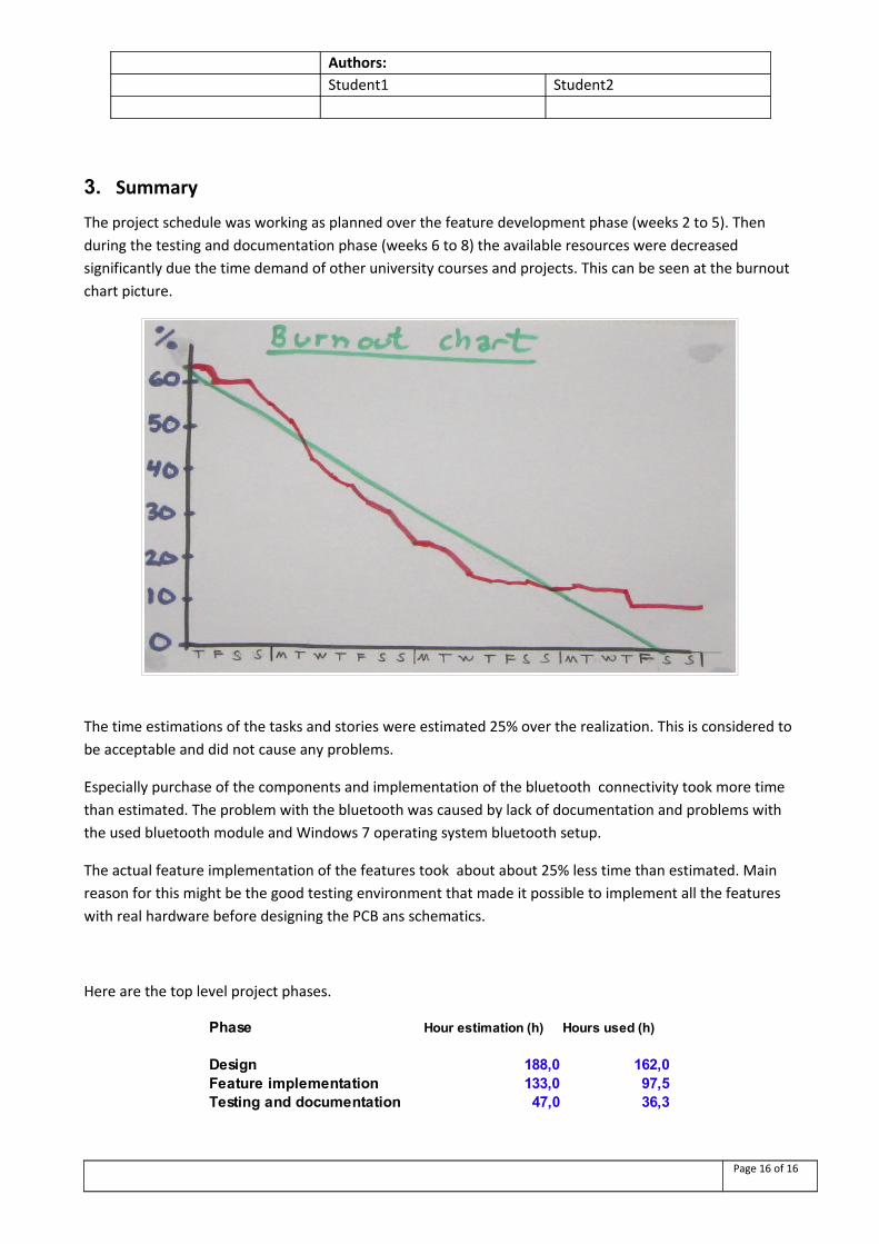
The project schedule was working as planned over the feature development phase (weeks 2 to 5). Then during the testing and documentation phase (weeks 6 to 8) the available resources were decreased significantly due the time demand of other university courses and projects. This can be seen at the burnout chart picture.
The time estimations of the tasks and stories were estimated 25% over the realization. This is considered to be acceptable and did not cause any problems.
Especially purchase of the components and implementation of the bluetooth connectivity took more time than estimated. The problem with the bluetooth was caused by lack of documentation and problems with the used bluetooth module and Windows 7 operating system bluetooth setup.
The actual feature implementation of the features took about about 25% less time than estimated. Main reason for this might be the good testing environment that made it possible to implement all the features with real hardware before designing the PCB ans schematics.
Here are the top level project phases.
Page 16 of 16
Phase Hour estimation (h) Hours used (h)
Design 188,0 162,0Feature implementation 133,0 97,5Testing and documentation 47,0 36,3