Embed Size (px)
Citation preview

Bachelor Thesis No. BEE 02-02
Blueboat
Ola Nilsson Tedh Stjärnborg
This thesis is presented as part of the Degree of Bachelor of Science in Electrical Engineering
Blekinge Institute of Technology
July 2002
_____________________________________ Blekinge Institute of Technology Department of Telecommunications and Signal Processing Examinator: Lennart Isaksson, Blekinge Institute of Technology

Blekinge institute of Technology Department of Telecommunication and Signal Processing
Blueboat 2
Abstract As today (July 2002) there is no doubt that a wireless revolution has arrived. As internet communication is growing stronger, more suitable and advanced techniques are used to integrate offices and home based networks to this new standard. A still somewhat sleeping and awaiting market actor to this new technology is the industrial one. The Blueboat application is meant to replace cables in a military marine system, showing that the wireless solution is as least as good and more flexible as the traditional based on cables. Our task was to send system information such as course, speed and depth from an internal rack to a client computer via Bluetooth. The system information is to be received, interpreted and logged on some kind of software (Bluboat) at the client computer. To do this we are using a microcontroller that is listening on a serial port to receive the information that is to be transmitted. In the microcontroller the data packets are reformatted to Bluetooth packets which are sent to a Bluetooth device connected to the microcontroller On the client side the Bluetooth packets are received and formatted so that it is possible to read real-time data on e.g. a laptop anywhere in the near facility. Key Words: Bluetooth, Microcontroller, Visual Basic, STK500/501, AT MEGA128
Sammanfattning Idag (juli 2002) är det ingen tvekan om att en trådlös revulotion är här. I takt med att Internetkommunikation växer sig starkare utvecklas mer anpassade tekniker för att integrera kontors och hemmanätverk med den nya standarden. En fortfarande något återhållsam och vaksam aktör på den trådlösa marknaden är industrin. Vår applikation är tänkt att ersätta kablar i ett militärt marint system och samtidigt visa att den trådlösa tekniken är minst så god och mer flexibel än den traditionella lösningen som är baserad på kablar. Vår uppgift bestod i att skicka systemdata såsom t.ex. kurs, hastighet och djup från en intern-rack till en klient dator via Bluetooth. Informationen ska tas emot, tolkas, visas och loggas i en mjukvara (Blueboat) på klientmaskinen. För att klara av detta använde vi oss av en mikrodator som lyssnar på en seriell port för att ta emot information som sedan ska skickas vidare. I mikrodatorn tas datapaketen emot och formateras om till Bluetooth-paket som sedan skickas till en Bluetooth enhet som är kopplad till mikrodatorn. På klientsidan tas Bluetooth-paketen emot och tolkas så att det är möjligt att läsa av realtidsdata på t.ex. en bärbar dator någonstans i närheten. Nyckelord: Bluetooth, Mikrodator, Visual Basic, STK500/501, AT MEGA128

Blekinge institute of Technology Department of Telecommunication and Signal Processing
Blueboat 3
Preface This work was done by Ola Nilsson and Tedh Stjärnborg as our final thesis of the Degree, Bachelor of Science in Electrical Engineering at Blekinge Institute of Technology (BTH). Lennart Isaksson became our supervisor, examiner and contact person at BTH. Martin Larsson and Marek Janiec were our contact persons at Kockums. This project has been very interesting for us in the sense of learning a new technology as Bluetooth is. We are convinced that the industrial market has a revolution of it own ahead in applying itself to the wireless community and we hope our work can be step in the right direction for it to happen. We would like to thank Martin, Marek and Lennart for the great support. We would also like to thank all others that supported us in this project.

Blekinge institute of Technology Department of Telecommunication and Signal Processing
Blueboat 4
Table of Contents 1 Introduction ..........................................................................................................................5
1.1 Background ..................................................................................................................... 5 1.2 How to read this report ................................................................................................... 6 1.3 Concept ........................................................................................................................... 7 1.4 Requirements specification............................................................................................. 8 1.5 Issues............................................................................................................................... 8
2 Hardware...............................................................................................................................9 2.1 Bluetooth......................................................................................................................... 9
2.1.1 Bluetooth air interface ..........................................................................................9 2.1.2 Bluetooth networking ...........................................................................................9 2.1.3 Bluetooth device...................................................................................................9 2.1.4 Bluetooth security...............................................................................................10 2.1.5 Problems in security of Bluetooth ......................................................................11 2.1.6 Bluetooth interference ........................................................................................11
2.2 Microcontroller ............................................................................................................. 11 2.2.1 Atmel STK500/STK501.....................................................................................12 2.2.2 Basic stamp.........................................................................................................14
3 Software...............................................................................................................................18 3.1 AVR studio 4 ................................................................................................................ 18 3.2 Microsoft Visual Basic 6.0 ........................................................................................... 21 3.3 National Instrument ...................................................................................................... 21 3.4 SMISK .......................................................................................................................... 22 3.5 IAR ICC Version 6 ....................................................................................................... 23
4 Construction........................................................................................................................24 4.1 MCU program............................................................................................................... 24
4.1.1 Initialize MCU....................................................................................................25 4.1.2 Initialize Bluetooth .............................................................................................27 4.1.3 Receiving data packets from data panel to MCU...............................................32 4.1.4 Build ACL-packet ..............................................................................................34 4.1.5 Send ACL-data ...................................................................................................36
4.2 Blueboat Software......................................................................................................... 37 4.2.1 Blueboat structure...............................................................................................37 4.2.2 Bluetooth setup...................................................................................................37
4.3 Connecting to the MCU................................................................................................ 39 4.3.1 Show incoming data ...........................................................................................40 4.3.2 Save incoming data.............................................................................................41 4.3.3 Show saved data .................................................................................................42
5 Results..................................................................................................................................44 6 Conclusions .........................................................................................................................45
6.1 BASIC STAMP 2 ......................................................................................................... 45 6.2 Codevision .................................................................................................................... 45
7 Glossary ...............................................................................................................................46 8 References ...........................................................................................................................47 9 Appendix – Visual Basic Comm Control..........................................................................48 10 Appendix – MCU Program AVR 128 .............................................................................55 11 Appendix – Bluetooth commands ...................................................................................59 12 Appendix – MSChart Example .......................................................................................60

Blekinge institute of Technology Department of Telecommunication and Signal Processing
Blueboat 5
1 Introduction 1.1 Background
Wireless communications became a commercial success in the early 1980s with the introduction of cellular communication systems in the United States, Japan, and Europe. Wireless communication systems of interest are for example WLAN, HomeRF and IRDA. These systems tend to operate in the Industrial-Scientific-Medical (ISM) band (902-928 MHz, 2400-24835 MHz, 5725-5780 MHz). This band is available for unlicensed use (Not everywhere) provided either the power levels are small enough or spread-spectrum modulation techniques are employed with larger transmitted power. The 2.4 GHz band is available world wide while the 900 MHz band is not available in some parts of the world (e.g., Europe). Another wireless system gaining significant attention is the cable replacement, wireless system Bluetooth (used in this project). It is being developed by a consortium of communication and computer companies (e.g., Ericsson, Nokia, IBM, Intel and Motorola). The objective of a Bluetooth system is to replace the cables connecting different components in a computer system with wireless links. Because it is a cable replacement the objective is for a very low cost, low range system. The range is about 10 meters with 0 dBm (1 milliwatt) transmitted power, but can be increased to 100 meters with larger power. Bluetooth uses the 2.4 GHz ISM band with frequency-hopped spread-spectrum. The maximum data rate is 721 kbps. It handles up to 8 devices in so-called piconets and can have up to 10 pico-nets operating in a coverage area. A competing system is HomeRF. HomeRF is geared more towards higher data rates and higher transmitted power. As with Bluetooth, HomeRF is a frequency-hopping system operating in the 2.4 GHz band. Products with data rates in the range of 2 Mbps with operating distances on the order of 150 feet are possible.

Blekinge institute of Technology Department of Telecommunication and Signal Processing
Blueboat 6
1.2 How to read this report
In addition to the headlines a report usually is built of, this report is divided into three major parts.
• Hardware: This part discusses different technical and hardware products that we have encountered during the thesis work. Both hardware that have been used and things that we had to abandon. It also describes Bluetooth in a both technical and outlined way so that readers without a technical background can understand it.
• Software: This part handles mostly the software that was used to develop the code in the different tools of the project e.g. the MCU and the client computer program “Blueboat “. It also describes a test-software we used to simulate the data traffic used in the military environment this thesis work was intended to work in.
• Construction: It is here the actual work is presented, it begins with the development of the Microcontroller and the board it is connected to and ends with the “Blueboat” software that was designed to work at the client computer.

Blekinge institute of Technology Department of Telecommunication and Signal Processing
Blueboat 7
1.3 Concept
In December 2001, we sent a request to se if there was any suitable project for us at Kockums in Malmoe. And we got an answer from Marek Janiec. The main goal with this project was to show that Bluetooth is a standard that works well in different military marine environments and that it has a satisfied compability. The system should send data in some kind of wireless technology from a data panel to a laptop where the information should be logged and presented in a suitable way. Since Bluetooth is one of the new interesting wireless standards and distance wasn’t an issue we all agreed on letting Bluetooth be our main way of transmitting the data.
Figure 1: System description Figure1 shows the overhead picture of what was to be done.
• The outgoing data panel sends continuously data in a RS422 format. • The RS422 / RS232 converts the signal so it can be received at the
Microcontroller (MCU) • The MCU receives the data from the data panel and rebuilds the data into
Bluetooth data packets and sends the packets to the Bluetooth device connected to the MCU.
• The data packets are sent from the Bluetooth device connected to the MCU to the device connected to the client computer.
• The Client computer finally receives, unpacks and shows/logs the data.
Outgoing data panel (RS422 format)
RS 422 / RS232 converter
MCU Bluetooth device Bluetooth device
Client Computer with Blueboat Software installed
Blekinge institute of Technology Department of Telecommunication and Signal Processing
Blueboat 8
1.4 Requirements specification
Hardware: • The hardware is to be powered with batteries. • Electro Magnetic Compatibility (EMC) with surrounding equipment is demanded.
Software: • Microcontroller (MCU):
o The software is to be able to receive data at both 9600 and 19200 baud. • Client software:
o Real time data should be shown in a suitable format. o It should be possible to log incoming data. o It should be possible to choose the rate of which packets are to be saved. o It should be possible to show logged data in a diagram form and to choose start
and stop time for viewing logged data.
1.5 Issues
• How will Bluetooth work in a military marine environment? • How do we solve security problems such as other people are able to “listen”
to the connection between the Bluetooth devices? • Which kind of Microcontroller is to be used? • Which are the best software development tools to use? • How do we log and present the data that is received at the client computer?
Blekinge institute of Technology Department of Telecommunication and Signal Processing
Blueboat 9
2 Hardware 2.1 Bluetooth
Bluetooth technology and standards provide the means for the replacement of cable that connects one device to another with a universal short-range radio link. The technology was initially developed for replacing cables, but has now evolved into not only being a cable replacement technique but also a technique to establish connection between several units.
The name Bluetooth comes from a Danish Viking and King, Harald Blåtand (Bluetooth in English), who lived in the latter part of the 10th century. Harald Blåtand united and controlled Denmark and Norway [1].
2.1.1 Bluetooth air interface To meet the requirements for the air interface a frequency band between 2.400 and 2.500 GHz was selected. Thus, the requirements regarding operating world wide, support for both data and speech and the limitations regarding physical characteristics (size and power consumption) were covered. This radio frequency band is the Industrial-Scientific-Medical, ISM band and ranges in Europe and the USA from 2.400 to 2.4835 GHz (in France and Spain only parts of this range are available) [2]. As a result, Bluetooth devices must be able to act in the range from 2.400 to 2.4835 GHz and be able to select a segment in the ISM band within which they can act. The ISM band is open to any radio system. Cordless telephones, garage door openers and microwave ovens operate in this band, where microwave ovens are the strongest source of interference.
2.1.2 Bluetooth networking When Bluetooth units are communicating, one unit is master and the rest of the units act as slaves. The master unit's system clock and the master identity are the central parts in the frequency hop technology. The hop channel is determined by the hop sequence and by the phase in this sequence. The identity of the master determines the sequence and the master unit's system clock determines the phase. In the slave unit, an offset may be added to its system clock to create a copy of the master's clock. In this way every unit in the Bluetooth connection holds synchronised clocks and the master identity, that uniquely identifies the connection [3]. To create Bluetooth packages you need some form of intelligence. So we had to program a microcontroller.
2.1.3 Bluetooth device The Bluetooth Education slot from Signal Control / Sense Tech is a development kit. It is designed with the ROK101007 radio from Ericsson which is compliant with Bluetooth version 1.0B. [6].

Blekinge institute of Technology Department of Telecommunication and Signal Processing
Blueboat 10
Figure 2: radio ROK101007
Features
• Possible to change Bluetooth module • Antenna included on the PCB • Point-to-multipoint • HCI layers available for communication • Reset button • Master/slave switch supported • Powered via USB, 5V DC/DC converter provides 3,3V • RS232 transceiver for direct connection to COM port on PC • RF output power 0dBm(class 2) • Range approx 10m The slot has a socket for easy attachment of Bluetooth module, accessible from a USB or a serial channel. The Education module is a point-to-multipoint module.
Figure 3: Bluetooth education device
2.1.4 Bluetooth security
Bluetooth security measures need to suit a peer environment, and so each Bluetooth unit is required to implement authentication, encryption and error checking in the exactly same manner. The most common threats are divided into three types: disclosure threats, integrity threats and denial of services.
• Disclosure threat involves the leakage of information from the system to a party that should not have seen the information and it is a great threat against the confidentiality of the information.
• The integrity threat involves an unauthorized change of the information in question. • The denial of service threat involves an access to a system resource being blocked
by a malicious attacker. It is a threat against availability of the system.

Blekinge institute of Technology Department of Telecommunication and Signal Processing
Blueboat 11
Confidentiality is a very vulnerable point in ad hoc networks. With wireless communication, anyone can sniff the messages on the air and without proper encryption all the information is available to anyone. On the other hand, without proper authentication, there is no point even to talk about confidentiality. If you cannot be certain who you are talking to, the confidentiality is poor anyway. And if the proper authenticity has been established, the securing of the connection with available keys is no problem. There are four entities used for maintaining the security at the link level.
• The Bluetooth device address (BD_ADDR), which is a 48 bit address (IEEE802). • Private authentication key, which is a 128 bit random number used for authentication
purposes. • Private encryption key, 8-128 bits in length used for encryption. • A random number (RAND), which is a frequently changing 128 bit random or pseudo
random number that is made by the Bluetooth device itself [8].
2.1.5 Problems in security of Bluetooth The encryption scheme of Bluetooth seems to be some weakness the 128 bit key length can be broken in (2^64) in some circumstances [5]. There is a problem in the unit key scheme. Authentication and encryption are based on the assumption that the link key is the participants shared secret. All the other information used in the procedures is public, so if a device A and B uses A’s unit key as their link key. And device C later on communicates with the device A, this means that device B has obtained A’s unit key earlier and can use the unit key with a faked device address to calculate the encryption key and therefore listen to the traffic, it can also authenticate itself to device A as device C and to device C as device A.
2.1.6 Bluetooth interference Interference from microwave ovens and radar installations can in some installations be a problem because they use the same frequencies as Bluetooth. However microwaves do not pass through buildings. Many different installations use the ISM band because they do not require government licensing. One of these bands is the worldwide 2.400-2.4835 GHz (The same frequencies that Bluetooth uses).
2.2 Microcontroller Microcontrollers are tiny computers that are designed for use in a wide array of applications. The rapid advances in semiconductor technology throughout the last decade of the 20th century have enabled the development of powerful new microprocessors and microcontrollers, bringing the embedded world computational power previously found only in supercomputers. Using microcontrollers with integrated FLASH memory modules provides greater flexibility with regard to field programmability, remote data storage, and prototyping. FLASH is a programmable, non-volatile memory technology, allows a FLASH device or a microcontroller with integrated FLASH to be programmed just before final assembly of a printed circuit board and in many cases, after the

Blekinge institute of Technology Department of Telecommunication and Signal Processing
Blueboat 12
microcontroller is actually installed on the board. In fact, a FLASH based microcontroller can execute a program that will erase its own FLASH In our case we needed some intelligence to create and send the Bluetooth packages from the data panel to the receiver at the laptop (se picture1). We developed the program for the microcontroller in c code, this code had to be translated into hex files that were done with a program called Image craft. At the receiver was another program built it should create and maintain the connection between the Bluetooth units and also log and present the data that was sent over the Bluetooth link. This particular program was mostly developed in VisualBasic6.0.
2.2.1 Atmel STK500/STK501
The Atmel STK500 board is designed to give designers a quick start to develop code on the AVR. It is also supplied with leds, ports switches and many other useful hardware solutions that easy can be used in different projects.
Figure 3: STK500 board
Features: • AVR Studio® Compatible • RS232 Interface to PC for Programming and Control • Regulated Power Supply for 10 - 15V DC Power • Sockets for 8-pin, 20-pin, 28-pin and 40-pin AVR Devices • Parallel and Serial High-voltage Programming of AVR Parts • Serial In-System Programming (ISP) of AVR Parts • In-System Programmer for Programming AVR Parts in External Target System • Reprogramming of AVR Parts • 8 Push Buttons for General Use • 8 LEDs for General Use

Blekinge institute of Technology Department of Telecommunication and Signal Processing
Blueboat 13
• All AVR I/O Ports Easily Accessible through Pin Header Connectors • Additional RS232 Port for General Use • Expansion Connectors for Plug-in Modules and Prototyping Area • On-board 2-Mbit DataFlash® for Nonvolatile Data Storage
Figure 4: STK500 board description.
The AVR STK500 board only provides oneRS232 port for communication. In our case we need two serial ports for communication one port to get data from the test panel and one to communicate with the Bluetooth device. The AVR STK501 is an expansion module that includes connectors, jumpers and a second rs232 port. It also gives you the opportunity to use faster and more complex processors as the ATmega128L that is used in our project. The STK501 kit is connected to the AVR STK500 board see picture7. Caution: do not use the STK501 board with a processor at the same time as an AVR is mounted on the STK500 board.
Blekinge institute of Technology Department of Telecommunication and Signal Processing
Blueboat 14
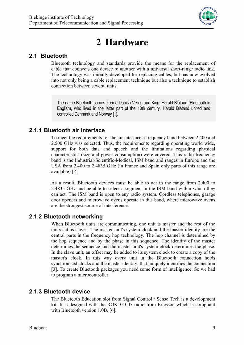
Figure 5: STK500 board with STK501 expansion board
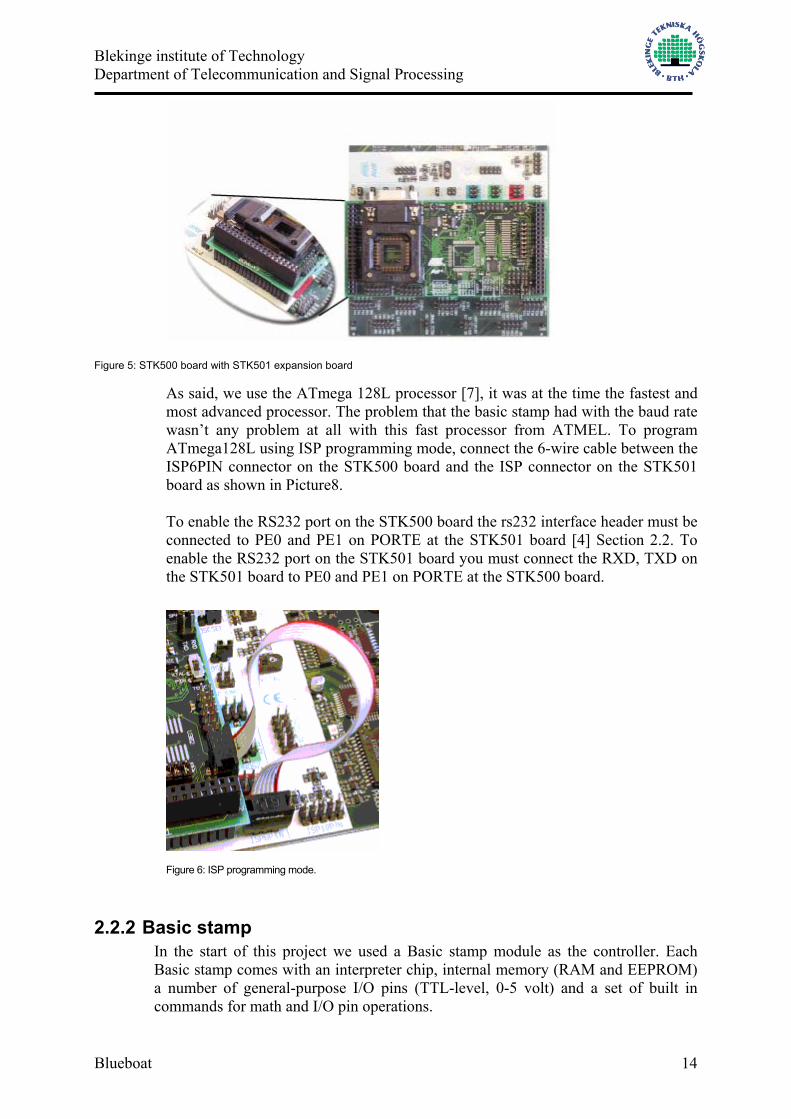
As said, we use the ATmega 128L processor [7], it was at the time the fastest and most advanced processor. The problem that the basic stamp had with the baud rate wasn’t any problem at all with this fast processor from ATMEL. To program ATmega128L using ISP programming mode, connect the 6-wire cable between the ISP6PIN connector on the STK500 board and the ISP connector on the STK501 board as shown in Picture8. To enable the RS232 port on the STK500 board the rs232 interface header must be connected to PE0 and PE1 on PORTE at the STK501 board [4] Section 2.2. To enable the RS232 port on the STK501 board you must connect the RXD, TXD on the STK501 board to PE0 and PE1 on PORTE at the STK500 board.
Figure 6: ISP programming mode.
2.2.2 Basic stamp In the start of this project we used a Basic stamp module as the controller. Each Basic stamp comes with an interpreter chip, internal memory (RAM and EEPROM) a number of general-purpose I/O pins (TTL-level, 0-5 volt) and a set of built in commands for math and I/O pin operations.

Blekinge institute of Technology Department of Telecommunication and Signal Processing
Blueboat 15
Basic stamps are capable of running a few thousand instructions per second and are programmed with a simplified, but customized form of the Basic programming language called PBASIC. The Basic stamp used in the beginning of the project is called BS2 and it will act as a “bridge”, it loads the Bluetooth packages with data from the test panel, it also tells the Bluetooth unit how to act. By programming the BS2 properly, the Bluetooth packages get the data that is sent to the test panel. The data form the test panel are sent on different I/O pins of the stamp to the Bluetooth device. Microcontrollers are often used when an embedded system needs some level of intelligence.
Programming the BS2 is relatively simple; just plug the 9-pin female side of a serial cable to an available serial port on your computer. Note: the serial cable should be a “straight-through” cable, not a null-modem cable. Connect the 9-pin male side of the cable to the DB9 connector on the development board.
Then run Basic Stamp editor software on the computer, write a program and download it to the BS2. The BS2 can be powered with a 9V battery, just plug it in on the side of the development board. The development board used is called Board of education and is specially designed for the BS2. The board provides a small breadboard for quickly prototyping simply or moderate circuits. We used the breadboard to build seriell ports on it they should send data to a LCD display and to the Bluetooth device. A more detailed description over the BS2 and the development board used is presented to you on the following page.
Figure 7: BS2

Blekinge institute of Technology Department of Telecommunication and Signal Processing
Blueboat 16
Pin Name Description 1 SOUT Serial out: connects to PC serial port RX pin (DB9 pin 2 / DB25 pin 3)
for programming
2 SIN Serial in: Connects to PC serial port TX pin (DB9 pin 3 / DB25 pin 2) for programming
3 ATN Attention: Connects to PC serial port DTR pin (DB9 pin1 / DB25 pin 20) for programming.
4 VSS System ground: (Same as pin 23) connects to PC serial port GND pin (DB9 pin 5 /DB25 pin 7) for programming.
5-20
P0-P15 General purpose I/O pins: each can sink 25 mA and source 20 mA however the total of all pins should not exceed 50 mA(sink) and 40 mA (source) if using the internal 5 Volt regulator.
21
VDD
5-volt DC input/output: if an unregulated voltage is applied to the VIN pin, then this pin will output 5-volt. If no voltage is applied to the VIN pin, then a regulated voltage between 4,5V and 5,5V should be applied to this pin.
22 RES Reset input/output: Goes low when input power consumption is less than 4, 2 volts, Causing the Basic stamp to reset. Can be driven low to force a reset.
23 VSS System ground: (Same as pin 4) connects to power supply’s ground (GND) terminal.
24 VIN Unregulated power in: Accepts 5,5 to 15VDC (6-40 VDC on BS2)
Figure 8: Board of education
When connecting the Bluetooth with the Microcontroller, you have to make a special cable. This type of connection is not a standard, as we know it. Connect pin7, 8 and pin1, 4, 9 together on each RS 232 port then connect pin 2 on the microcontroller with pin 3 on the Bluetooth unit. Connect pin 2 on the Bluetooth unit with pin 3 on the microcontroller and connect pin 5 on the Bluetooth unit to pin 5 on the microcontroller.

Blekinge institute of Technology Department of Telecommunication and Signal Processing
Blueboat 17
Figure 9: RS232 Pin connection

Blekinge institute of Technology Department of Telecommunication and Signal Processing
Blueboat 18
3 Software 3.1 AVR studio 4
When programming the ATmega128L the AVR Studio 4 was used. AVR Studio 4 is an Integrated Development Environment for writing and debugging AVR applications in Windows environments. AVR Studio 4 provides a project management tool, source file editor, chip simulator and in-circuit emulator interface for the powerful AVR 8-bit RISC family of microcontrollers. In addition, AVR Studio 4 supports the STK500, 501 development boards, which allow programming of all AVR devices, and the JTAG interface on-chip emulator. The software includes the following features: • Integrated Development Environment (IDE) for Writing, Compiling and Debugging Software • Fully Symbolic Source-level Debugger • Configurable Memory Views, Including SRAM, EEPROM, Flash, Registers and I/O • Unlimited Number of Breakpoints • Trace Buffer and Trigger Control • Online HTML Help • Variable Watch/Edit Window with Drag-and-Drop Function • Extensive Program Flow Control Options • Simulator Port Activity Logging and Pin Input Stimuli • File Parser Support for COFF, UBROF6, UBROF8, and Hex Files • Support for C, Pascal, BASIC and Assembly Languages • Support for All Atmel AVR In-Circuit Emulators and the JTAG Emulator • Support for the STK500, 501 Development Board AVR Studio 4 supports all Atmel AVR devices.
AVR Studio 4 combines an editor, project manager, assembler/compiler interface and debugger in one easy-to-use development tool. AVR Studio’s powerful editor allows seamless integration with any compiler and linker. The source code can be edited directly in the debugger source window with syntax coloring support for both C and Assembly. When an emulator is detected on the serial port, AVR Studio automatically enters emulator mode. If an emulator is not detected, AVR Studio starts in simulator mode. The user interface is identical. AVR Studio 4 includes configuration software to update the AVR emulator and the STK500 development board to their latest firmware versions. Self-test and diagnostic software for the emulators is also included. AVR Studio 4 is the front-end software for configuring and programming AVR devices using the STK500 development board. No other software is required for programming any AVR device in any programming mode. The entire development process from code writing through debugging to production is within reach with AVR Studio 4.

Blekinge institute of Technology Department of Telecommunication and Signal Processing
Blueboat 19
AVR studio provides a source file editor that is used to set the different fuses that has to be set for the microcontroller to work properly. It is also used to program a hex file into the AVR target device, select “STK501” board from “Tools” menu in AVR studio. Select the AVR target device from the pull-down menu on the “program” tab in our case ATmega128 .The Input HEX File in the “flash” menu must be selected then navigate to the directory where your hex file you want to use is and select it in this example program.hex se picture 9.
Figure 10: AVR Studio programming. Click the “erase” button followed by the “program” button. The status led will now turn yellow while the part is programmed, and when programming succeeds, the LED will turn green. Under the tab “Fuses” must some selections be done or else won’t the microcontroller work properly in our case se Figure 10 for example must the external clock be set to Ext.clock: startup time 6 CK+ 64 ms.
Blekinge institute of Technology Department of Telecommunication and Signal Processing
Blueboat 20
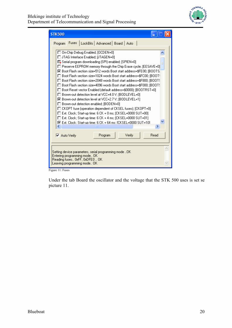
Figure 11: Fuses Under the tab Board the oscillator and the voltage that the STK 500 uses is set se picture 11.

Blekinge institute of Technology Department of Telecommunication and Signal Processing
Blueboat 21
Picture 12: Board
3.2 Microsoft Visual Basic 6.0
Visual Basic 6.0 is a complete suite of tools for developing solutions based on Microsoft Windows. Visual Basic was used to create the software Blueboat on the client computer system. It is relatively easy to create advanced programs in this development tool from Microsoft.
3.3 National Instrument
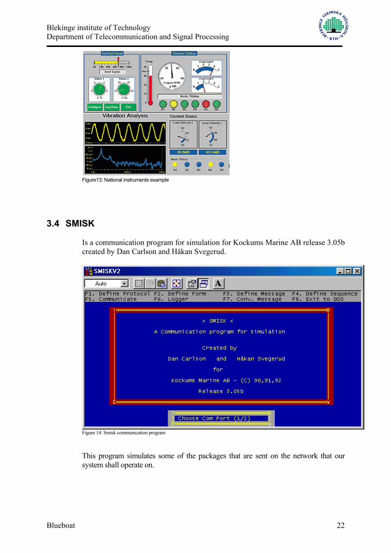
National Instruments release of Measurement studio is a set of fully integrated measurement tools that complements Visual Basic. Measurement Studio 6.0 provides all the tools you need to create a variety of integrated test, measurement, and control applications in the programming language. With the new version's enhanced visualization tools, can you quickly display your data on real-time 3D or 2D graphs and charts that would take hours to build without Measurement Studio? To make visual displays more descriptive, can you supplement those graphs with annotations to label or explain significant dips or spikes in the data and use cursors to determine exact coordinates on a 3D graph. The graphs, buttons, sliders, and LEDs use 3D hardware acceleration to speed applications while providing a professional interface.
Blekinge institute of Technology Department of Telecommunication and Signal Processing
Blueboat 22
Figure13: National instruments example
3.4 SMISK
Is a communication program for simulation for Kockums Marine AB release 3.05b created by Dan Carlson and Håkan Svegerud.
Figure 14: Smisk communication program
This program simulates some of the packages that are sent on the network that our system shall operate on.

Blekinge institute of Technology Department of Telecommunication and Signal Processing
Blueboat 23
3.5 IAR ICC Version 6
ImageCraft AVR C compiler is a modern GUI Development Environment. It is a program for developing microcontroller applications using the ANSI standard C language. It can develop “Hex files” of the source code that the microcontroller can run. It does also provide an application builder that makes the programming easier.

Blekinge institute of Technology Department of Telecommunication and Signal Processing
Blueboat 24
4 Construction This part describes how the whole system was developed piece by piece with the help of the hardware and software described earlier in the report. We divide the project into two major parts which can be divided into smaller sections.
• MCU program, this program receives data and rebuilds it into Bluetooth packets.
• Client software, Blueboat, receives displays and logs the incoming data.
4.1 MCU program This program was developed using the C programming language. The main task for this program is to receive data packets and rebuild it so it can be transmitted over the Bluetooth link. On the MCU we have two different RS232 connections, one to talk to the connected Bluetooth unit (UART0), the other listens to the data panel (UART1). After the initialization of both the MCU and the connected Bluetooth unit UART1 starts listening for traffic. The data from the panel is continuously being sent, so the first task is to find out when a packet starts and when it is finished. When this is done, e.g. we have a whole packet; we have to rebuild it into a Bluetooth data packet which is called an ACL packet. The functionality of the program is shown in the flowchart described in Figure 15, and below the flowchart we describe the program step by step.
Start
init MCU
init Bluetooth
receive data from MCU
send ACL data
complete packet?
YesNo
build ACL-packet

Blekinge institute of Technology Department of Telecommunication and Signal Processing
Blueboat 25
Figure 15: MCU program flowchart
4.1.1 Initialize MCU This is where the STK501 board is initialized. Here we set the light diodes to output mode so that we have someway of telling what the status of the MCU is at different stages of the system. We also setup the both UARTs to both receive and transmit at the right speed. The UART connected to the Bluetooth unit operates at the speed of 57600 baud and the UART connected to the data panel works at the speed of either 9600 or 19200 baud depending on which port on the data panel the MCU is connected to. Creating code for the MCU To create code for our MCU, the ATMEGA 128 we used the program ICC AVR6.0 from ImageCraft Development Tools. This is a fairly easy program to use if, like us, you are new to program an AVR MCU. To enable all registers and ports we used a function called Application builder. This tool lets you choose what kind of processor you are using (Figure 16) and when ATMEGA128 chosen all its registers are available. When all the settings are set, you generate the code by pressing OK.
Figure 16: Application builder

Blekinge institute of Technology Department of Telecommunication and Signal Processing
Blueboat 26
Light diodes To be able to communicate with the eight diodes on the STK500 we have to connect them to an available port (A-D), PORTB in our case. This is done with the help of a cable like the one on figure 8. When the cable is connected we program a value for the PORTB. If we set PORTB = 0x00 all the diodes are light and if we set it to 0xFF all the diodes are turned off. UART To be able to send and receive anything from and to the MCU we use the two UARTs (Universal Asynchronous Receiver and Transmitter) placed on the STK500/501. One UART is placed on the STK500 and the other on the STK501 board, as seen on figure 7. There are two ways of getting data on the UART, either you poll the device or you use an interrupt function. We used the latter one because of the continuous data flow from the panel the MCU is connected to. How to choose the settings for UARTs are shown in figure 17.
Figure 17: UART settings

Blekinge institute of Technology Department of Telecommunication and Signal Processing
Blueboat 27
4.1.2 Initialize Bluetooth Now, when the code for all the registers is done the next step in the MCU program is to make contact and initialize the Bluetooth unit connected to the MCU. To do this we have to construct different Bluetooth codes to utilize the Bluetooth stack. Before sending any data packets the client computer we have to do the following on the Bluetooth unit:
• Commit HCI-reset Resets the Bluetooth Host Controller, Link Manager and the Radio Module.
• Commit Write Scan Enable This is to set the unit in search mode for inquiry attempts from other units in the vicinity. This is necessary for us so that we can find the unit from our client program.
• Commit Set Event Filter This is used so that we can specify different events generated by the Bluetooth unit.
• Naming the Bluetooth unit To be able to identify the Bluetooth unit from the Client Computer software we name the Bluetooth unit connected to the MCU “BLUEBOAT”.
4.1.2.1 Communicate with the Bluetooth unit When making contact to the Bluetooth unit over a UART transport layer we make use of the HCI interface (Host Controller Interface) this is the interface which links a Bluetooth host to a Bluetooth module. In this case the MCU acts as the host. There are four kinds of HCI packets that can be sent via the UART Transport Layer.
• HCI Command Packet, used by the host to control the module and to monitor its status. HCI Command Packets can only be sent to the Bluetooth Host Controller
• HCI Event Packet, used by the module to inform the host of changes in the lower layers. HCI Event Packets can only be sent from the Bluetooth Host Controller
• HCI ACL Data Packet, used to send data. Can be sent both to and from the Bluetooth Host Controller.
• HCI SCO Data Packet, used to send sound. Can be sent both to and from the Bluetooth Host Controller.
4.1.2.2 HCI Command packet The HCI Command Packet is used to send commands to the Host Controller, which in this case is the Bluetooth unit connected to the MCU, from the Host (MCU). The format of the HCI Command Packet is shown in Figure 18, and the definition of each field is explained below. When the Host Controller completes most of the commands, a Command Complete event is sent to the Host. Some commands do not receive a Command Complete event when they have been

Blekinge institute of Technology Department of Telecommunication and Signal Processing
Blueboat 28
completed. Instead, when the Host Controller receives one of these commands the Host Controller sends a Command Status event back to the Host when it has begun to execute the command. Later on, when the actions associated with the command have finished, an event that is associated with the sent command will be sent by the Host Controller to the Host.
Figure 18: HCI-Command packet OpCode The start of every HCI command begins with a two byte OpCode that is used to identify different types of commands. The OpCode is divided into two different fields. The OGF (Opcode Group Field) and the OCF (OpCode Command Field). The OGF occupies the upper 6 bits of the Opcode, while the OCF occupies the remaining 10 bits. The Codes and commands are all found in the Specification of the Bluetooth System [5]. Example: Creating the OpCode for HCI-reset: CODE Hex bit OGF 03 0000 0011 OCF 0003 0000 0000 0000 0011
Since the OGF only consists of 6 bits, and OCF of 10 bits, as shown in figure 18, the OpCode results like this:
Important Note! Something that is very important when working with Bluetooth is the fact of using the little endian format. This is a computer architecture in which, within a given 16- or 32-bit word, bytes at lower addresses have lower significance (the word is stored "little-end-first"). So when the Bluetooth packet is finished you have to “turn the significance around”

Blekinge institute of Technology Department of Telecommunication and Signal Processing
Blueboat 29
OpCode: 000011 0000000011 And when making two bytes of this the result is: Byte 1 = 0000 1100 = 0x0C (Hexadecimal) Byte 2 = 0000 0011 = 0x03 (Hexadecimal) So when concatenating the two bytes we get the OpCode: 0x0C03 And often we think we are thru constructing our HCI OpCode here, but this is not the fact. As mentioned before, Bluetooth uses the little endian format and therefore we have to turn the bytes around. So the final OpCode is: 0x030C Parameter total length Lengths of all of the parameters contained in this packet measured in bytes. In the example we are creating, the HCI-reset command doesn’t have any parameters so therefore the value is 0x00. Building the HCI-reset command To tell difference between the different HCI-packets we use a 1 byte big identifier in the start of a HCI-packet. The identifiers for each kind of packets are described in figure 19. HCI packet type HCI packet identifier HCI Command Packet 0x01 HCI ACL Data Packet 0x02 HCI SCO Data Packet 0x03 HCI Event Packet 0x04
Figure 19: UART settings The total HCI reset command results as: Parameter Value HCI packet type 0x01 OpCode 0x030C Parameter total length: 0x00 Complete package to send: 0x01030C00
4.1.2.3 HCI Event Packet When a HCI-command packet is sent from the MCU, the Bluetooth returns a HCI-Event packet which let us know the status and/or the result of the command we sent. The HCI-Event package is very similar to the HCI-Command packet. The
OGF OCF

Blekinge institute of Technology Department of Telecommunication and Signal Processing
Blueboat 30
structure of an Event package is demonstrated in figure 20, and the definition of each field is explained below.
Figure 20: HCI-Event packet Event Code This is a field with an event code that tells us the status or success of the HCI-command packet that triggered the event. Parameter Total Length This field tells us the total length of all parameters measured in bytes. Event Parameter 0-n Each event has a specific number of parameters associated with it. These parameters and the size of each of the parameters are defined for each event. Each parameter is an integer number of bytes in size. Example: Receiving event packet To continue the example of the HCI-reset command that was described earlier we can view an HCI-event that would have been triggered of a successful HCI-reset command. Incoming HCI-event packet: 0x 04 0E 04 08 03 0C 00 Value Parameter Description 0x04 HCI packet type Description of HCI-Event packet 0x0E Event Code Command Complete, the value of the
event codes can be found in the” Specification of the Bluetooth System [5].
0x04 Parameter total length:
Total size of parameters measured in bytes.

Blekinge institute of Technology Department of Telecommunication and Signal Processing
Blueboat 31
0x08 Parameter 0 The Number of HCI command packets which are allowed to be sent to the Host Controller from the Host.
0x030C Parameter 1 Opcode of the command which caused this event.
0x00 Parameter 2 This is the return parameter(s) for the command specified in the Command Opcode event parameter. The return parameter in this case: 0x00 means that the command was executed successfully.
4.1.2.4 Sending packets from the MCU To construct the packages that is to be sent to the Bluetooth unit we simply construct an array for each command that is to be sent. Then we send it byte by byte into the function that was constructed in the ICC AVR Application builder. Example code: sending HCI-reset from MCU
4.1.2.5 Receiving packets from Bluetooth unit to MCU To receive packets from the Bluetooth unit connected to the MCU we use the interrupt function created in ICC AVR Application builder. We continue with our example of how an HCI-Event packet is received and handled in the MCU code when a HCI-reset command has been sent. Example code: receiving Event packet from Bluetooth unit
//Initialize the Array: unsigned char reset[4] = {0x01,0x03,0x0C,0x00}; //This function is made by Application builder void USART0_Transmit( unsigned char data ) {
// Wait for empty transmit buffer while ( !( UCSR0A & (1<<UDRE0)) ) ; // Put data into buffer, sends the data UDR0 = data;
} void main(void) {
int i=0; while(i<4) { USART0_Transmit(reset[i]); i++;
}

Blekinge institute of Technology Department of Telecommunication and Signal Processing
Blueboat 32
Figure 21: UART program example
4.1.3 Receiving data packets from data panel to MCU At this stage the Bluetooth unit connected to the MCU is fully initialized and the MCU is now ready to receive data from the data panel. Under this thesis work we haven’t had access to the real data panel and have therefore simulated the data by the help of the program SMISK that has been developed by Kockums. Since the actual type of data is classified and therefore not presentable, we can only show the format of the data packets as presented by SMISK.
//function created by Application builder void uart0_rx_isr(void) // int ReadLengthCnt is a global counter that counts each byte received // char ReadData[] is a global Array where the incoming bytes are stored //UDR0 is the MCU register that stores the received byte from the UART0 buffer { int i = 0; int readDataLength = 0; ReadData[ReadLengthCnt++] = UDR0; //the third byte in a Bluetooth packet should contain the total size of remaining //parameters in bytes.
if (ReadLengthCnt == 3) {
//Read the Data size and store it in ReadDataLength ReadDataLength = (int)ReadData[2];
} //When a whole packet is received ReadLengthCnt should be equal to //3+ReadDataLength if (ReadLengthCnt == (3+ReadDataLength)) {
//An example to se if e.g. an Event packet contains an OK for a HCI-//reset command. // ReadData[1] is the Event Code //ReadData[6] is the return parameter (0x00 = OK) if (ReadData[1] == 0x0E && ReadData[6] == 0x00) //when a whole packet is received we have to reset the counter ReadLengthCnt=0;
} }

Blekinge institute of Technology Department of Telecommunication and Signal Processing
Blueboat 33
4.1.3.1 SMISK data format The data block consists of a Header followed by the actual data block message and ended by a tail. Example of a SMISK data block message:
Header DLE, STX
Data block Data
Tail DLE, ETX
The character sequence DLE, STX forms the header of the data block message. The character sequence DLE, ETX terminates the data block message. Data forms the data block of the message and compromises code independent data, i.e. even DLE, STX and ETX are allowed to occur in the data block. DLE forms a synchronization control character. Each time DLE occurs as data in the data block it is copied by the sender forming a transmitted sequence of two consecutive DLE (DLE DLE).
4.1.3.2 Extracting data packets When receiving data from the data panel to the MCU we use the same technique as when we received data from the Bluetooth unit. We use an interrupt function, but this time we use UART1 placed on the STK501 expansion board. The code for the interrupt function is created by the ICC application wizard. The difference in this case is that there is now way for us to know the size of the data packet in advance since consecutive DLEs can be placed in the data block area. So the way to tell how a packet starts and ends is simply to find the right sequence of header and tail bytes. This is an example code of how to find the header and tail sequence. Needed to know is that: DLE = 0x10 STX = 0x02 ETX = 0x03
Blekinge institute of Technology Department of Telecommunication and Signal Processing
Blueboat 34
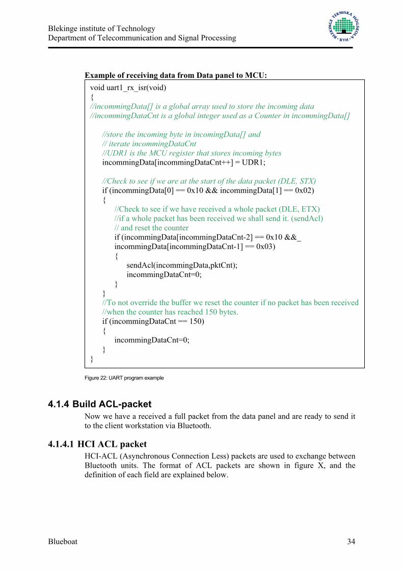
Example of receiving data from Data panel to MCU:
Figure 22: UART program example
4.1.4 Build ACL-packet Now we have a received a full packet from the data panel and are ready to send it to the client workstation via Bluetooth.
4.1.4.1 HCI ACL packet HCI-ACL (Asynchronous Connection Less) packets are used to exchange between Bluetooth units. The format of ACL packets are shown in figure X, and the definition of each field are explained below.
void uart1_rx_isr(void) { //incommingData[] is a global array used to store the incoming data //incommingDataCnt is a global integer used as a Counter in incommingData[] //store the incoming byte in incomingData[] and // iterate incommingDataCnt //UDR1 is the MCU register that stores incoming bytes
incommingData[incommingDataCnt++] = UDR1; //Check to see if we are at the start of the data packet (DLE, STX) if (incommingData[0] == 0x10 && incommingData[1] == 0x02) { //Check to see if we have received a whole packet (DLE, ETX) //if a whole packet has been received we shall send it. (sendAcl) // and reset the counter
if (incommingData[incommingDataCnt-2] == 0x10 &&_ incommingData[incommingDataCnt-1] == 0x03)
{ sendAcl(incommingData,pktCnt); incommingDataCnt=0;
} } //To not override the buffer we reset the counter if no packet has been received //when the counter has reached 150 bytes. if (incommingDataCnt == 150) {
incommingDataCnt=0; }
}

Blekinge institute of Technology Department of Telecommunication and Signal Processing
Blueboat 35
Figure 23: HCI-ACL data packet Connection Handle This is a 12 bit identifier for each connection the Bluetooth unit has made with other Bluetooth units in the vicinity. PB Flag PB stands for Packet Boundary and tells the Bluetooth unit if the packet is a continuing fragment packet of Higher Layer Message or if it is the start of a new packet. BC Flag BC stands for Broadcast and tells the Bluetooth unit if this is a point to point message or if it is a broadcast message. Data total length Length of data measured in bytes. Data The actual data that we have collected from the data panel. When sending data to an Ericsson Bluetooth module we have to store the data in an L2CAP packet (figure 24) in this part of the ACL packet. The L2CAP fields are explained below.
Figure 24: L2CAP packet Length Length indicates the size of information payload in bytes, excluding the length of the L2CAP header. The length of an information payload can be up to 65535 bytes. The Length field serves as a simple integrity check of the reassembled L2CAP packet on the receiving end. Channel ID The channel ID identifies the destination channel endpoint of the packet. The scope of the channel ID is relative to the device the packet is being sent to. Information (payload)

Blekinge institute of Technology Department of Telecommunication and Signal Processing
Blueboat 36
This becomes the actual data storage.
4.1.5 Send ACL-data This is an example of how to send an ACL-packet. The function “sendACL” is called from the earlier example in figure 22.
Figure 25: Send ACL-packet program example
//inparameters is the actual data as a pointer to an array and the value of the //length of the array as an integer void sendAcl(char *data, int dataLength) {
int i = 0; int TotalSize = dataLength+ 4; //this is for adding the ACL-id byte unsigned char ACLpkt[150] = {0}; //the actual ACL packet ACLpkt[0]=0x02; //ACL-pkt ACLpkt[1]=ConnectionID; //connectionID, earlier extracted and a global variable ACLpkt[2]=0x20; //PB and BC ACLpkt[3]=TotalSize; //datasize + header in bytes(byte1) ACLpkt[4]=0x00; //datasize + header in bytes(byte2) ACLpkt[5]= dataLength; //datasize/L2CAP (byte1) ACLpkt[6]=0x00; //datasize/L2CAP (byte2) ACLpkt[7]=0x00; // L2CAP ChannelID. ACLpkt[8]=0x00; // L2CAP ChannelID. for(i=0;i<dataLangd;i++) //Fill the data into the packet { ACLpkt[i+9] = data[i]; } i=0; //reset the counter //As long as there is anything to send, send it //USART0_Transmit puts the byte in the transmit register of the MCU while (i<TotalSize+5) {
USART0_Transmit(ACLpkt[i]); i++;
} }

Blekinge institute of Technology Department of Telecommunication and Signal Processing
Blueboat 37
4.2 Blueboat Software Blueobat is developed in Microsoft’s Visual Basic 6.0 and is the software that is developed to be installed on the client computer (figure 1). The task for this program is to:
• Setup the Bluetooth device connected to the Client computer • Find and connect to the Bluetooth units connected to the MCU. • When connection is established, show incoming data in real-time. • Save incoming data. • Be able to show saved data, and present it in a graphical way.
When beginning the thesis work we had two major options on how to work with the Bluetooth unit connected to the client computer. We could either build our own Bluetooth commands or use free software, C-Stack [9], that is made for working with Visual Basic or Visual C++. We decided early on to use and create our own Bluetooth commands in order to get a wider understanding of how the technique works.
4.2.1 Blueboat structure Blueboat is organized in a tabulated menu structured hierarchy (figure 26). The structure of the different tabs is described below.
Figure 26: Blueboat menu structure
4.2.2 Bluetooth setup This is the startup tab that is shown when Blueboat is executed. This part of the program has mainly one function: To search for and connect to Bluetooth devices that are named “BLUEBOAT”. This can be done in two different ways.
• Automatically by pressing the button “Connect”

Blekinge institute of Technology Department of Telecommunication and Signal Processing
Blueboat 38
• Manually by sending pre-assigned commands to the Bluetooth unit connected to Blueboat.
In the Bluetooth setup tab there are also different option fields so that you can choose.
• Which Com port the Bluetooth device is connected to. • Which Baud Rate to operate in. • Show HCI and ACL details. This information is for an operator to check
for eventual faults or mishaps in the communication with the Bluetooth device. Here it is possible to se exactly what is being sent and what is coming in on the Com Port.
• It is possible to choose the inquiry time, which is the time variable the Bluetooth device uses in the search for other devices in the vicinity. The longer the time the more likely it is to find devices that are further away.
It is also possible to send and create own messages to the connected Bluetooth device by typing them in the field “Raw” and by pressing send. The listbox “Fast commands” consists of the most used HCI-commands such as “Reset, Inquiry and WriteScanEnable. There are also three larger textboxes that gives the user information about what information that is being sent and received, which devices are found and which devices that are connected to Blueboat. An incoming Event packet is showed in the textbox “Info” as described in figure 27.
Figure 27: Incoming Event packet in Blueboat

Blekinge institute of Technology Department of Telecommunication and Signal Processing
Blueboat 39
4.3 Connecting to the MCU This is the overhead view of how Blueboat searches and connects to the right devices.
Open ComPort In Visual Basic it is very simple to use and program how to send and receive information via the serial ports, one simply adds the component Microsoft Comm Control 6.0. This extra component makes it possible to set the settings for your serial port. The default settings to exchange information with the Ericsson Bluetooth unit are: Baud Rate 57600 bps Parity type no parity Number of data bits 8 Number of stop bit 1
The Baud Rate and which comport to use are both values that can be changed in Blueboat. Init Bluetooth To initiate the Bluetooth device we followed the same steps as when we initiated the device that is connected to the MCU, with the difference that we don’t name this device. (The building of the HCI command packets are described in 4.1.2.1.)
1. Reset the stack 2. Write Scan Enable 3. Set Event Filter
Blekinge institute of Technology Department of Telecommunication and Signal Processing
Blueboat 40
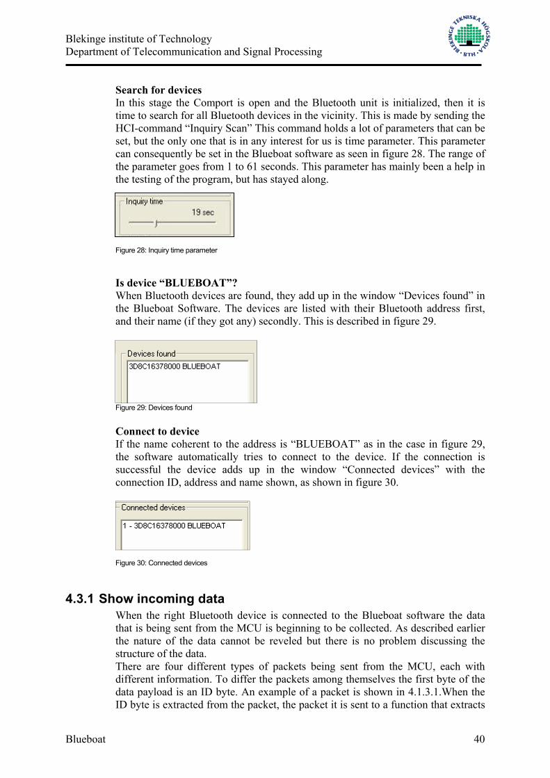
Search for devices In this stage the Comport is open and the Bluetooth unit is initialized, then it is time to search for all Bluetooth devices in the vicinity. This is made by sending the HCI-command “Inquiry Scan” This command holds a lot of parameters that can be set, but the only one that is in any interest for us is time parameter. This parameter can consequently be set in the Blueboat software as seen in figure 28. The range of the parameter goes from 1 to 61 seconds. This parameter has mainly been a help in the testing of the program, but has stayed along.
Figure 28: Inquiry time parameter
Is device “BLUEBOAT”? When Bluetooth devices are found, they add up in the window “Devices found” in the Blueboat Software. The devices are listed with their Bluetooth address first, and their name (if they got any) secondly. This is described in figure 29.
Figure 29: Devices found Connect to device If the name coherent to the address is “BLUEBOAT” as in the case in figure 29, the software automatically tries to connect to the device. If the connection is successful the device adds up in the window “Connected devices” with the connection ID, address and name shown, as shown in figure 30.
Figure 30: Connected devices
4.3.1 Show incoming data When the right Bluetooth device is connected to the Blueboat software the data that is being sent from the MCU is beginning to be collected. As described earlier the nature of the data cannot be reveled but there is no problem discussing the structure of the data. There are four different types of packets being sent from the MCU, each with different information. To differ the packets among themselves the first byte of the data payload is an ID byte. An example of a packet is shown in 4.1.3.1.When the ID byte is extracted from the packet, the packet it is sent to a function that extracts

Blekinge institute of Technology Department of Telecommunication and Signal Processing
Blueboat 41
all the data and shows it in either the tab “Packet B, Packet B/ M/ S, Packet L / data log” the different tabs are shown in figure 26. A view of how the data is shown in real time is shown in figure 31, the picture is a bit distorted so that no details can be shown. The meaning of the picture is to show the different type of speedometers and other visual effects to show the data.
Figure 31: Real-time data view in Blueboat
4.3.2 Save incoming data In addition to showing the data in real time, the information is also being saved so that it is possible to collect and view old data. The discussion about how to save the data was mainly divided in two different ways. One was to build a data base. The advantages of that would be a greater flexibility in handling it but the complexity of a database came to make another decision. But instead we saved the incoming data packets in different text files. The text files are named after the ID byte so if the incoming data packet has an ID byte of 0x46 (F) the name of the text file is “paket_F.txt”. We also added a knob so that it is possible to choose the save rate of the packets. This feature is added so that the text files don’t grow to alto huge sizes when the software is run for a very long time. The picture of the knob is shown in figure 32.

Blekinge institute of Technology Department of Telecommunication and Signal Processing
Blueboat 42
Figure 32: Packet save rate in seconds
4.3.3 Show saved data To show logged data we use the component Microsoft Chart Control 6.0 in Visual Basic. This tool makes it possible to draw charts with all the data connected to a timestamp to when it was saved. It is also possible to choose in what time span logged data is to be shown. This is done with the help of a “Date picker”. With this tool you can choose start and stop date (year, month, day and time) for the information you want to see. This is illustrated in figure 33. You can also choose the different types of packets to show.
Figure 33: How to choose start and stop date for logged data
An example of the Chart result is shown in figure 34. This picture is also somewhat distorted in order not to show any classified data.

Blekinge institute of Technology Department of Telecommunication and Signal Processing
Blueboat 43
Figure 34: An example of data chart in Blueboat

Blekinge institute of Technology Department of Telecommunication and Signal Processing
Blueboat 44
5 Results This thesis work resulted in both hardware and software products. The hardware consists of the STK500/501 board with an ATMEL MEGA 128 processor with a connected Bluetooth Device. The software is the client computer program “Blueboat”. This thesis work and products was intended to be installed in a military marine environment, but has due to unfortunate circumstances yet not been able to proof itself there. Therefore are the results hard to summarize. But with the simulation program “SMISK” developed by Kockums AB we can at least simulate sending and receiving packets that are built in the same way as in the real environment and by judging with our results Bluetooth and “Blueboat” works just as intended. The ATMEL MEGA 128 processor is also a very pleasing hardware due to its speed and relatively easy programming tools. As Bluetooth is the wireless communication method at this time that is the least sensitive to disturbances, the possibility for it to work in the intended environment is good. The negative aspect would be the effective range in which Bluetooth can work. The range without disturbances and physical obstacles is at this moment 10 meters, but in a narrow environment with a lot of steel walls the range could decrease somewhat. The software “Blueboat” is a tool not only for receiving and logging data. The problems with how to save the incoming data was solved with creating individual text files for each kind of packet that was received. It is also possible to send, view and receive Bluetooth commands and is in that way also a product that can be used to setup different Bluetooth solutions and test.
Blekinge institute of Technology Department of Telecommunication and Signal Processing
Blueboat 45
6 Conclusions When the thesis work began we had a fair knowledge about programming and using the Bluetooth commands. The things we didn’t know anything about was the programming of a Microcontroller and the development of software in Microsoft’s Visual Basic. The time and effort circled round these to tasks and became a greater obstacle than we ever intended starting the project.
6.1 BASIC STAMP 2 After a time of programming and developing the serial ports on the BS2, and on the Board of Education the results were not there. We sent Bluetooth commands but got no answers. Either was the serial port we built wrong or could the Bluetooth device not understand the commands we sent (it could be anything in the communication between the BS2 and the Bluetooth device). After some studies in the BS2 manual the answer was brought up the BS2 baud range is 243 to 50K and the Bluetooth unit must at least use the baud rate 56K. So we had to abandon the BS2 MCU and the board of education because it couldn’t measure up (the baud rate of the BS2 was to low).
6.2 Codevision Codevision is a development environment such as Imagecraft. We started to develop some code with Codevision in the beginning of the programming on the microcontroller STK500/501. But we used a free version that only let us provide codes that was smaller than 200kbit so after some code writing we soon understood that it wouldn’t be enough with codes that was smaller than 200kbit. We abandon Codevision and used a full version of Imagecraft instead.

Blekinge institute of Technology Department of Telecommunication and Signal Processing
Blueboat 46
7 Glossary
BD_ADDR : Bluetooth Device Address. Each Bluetooth transceiver is allocated a unique 48-bit device address. BTH: Blekinge Tekniska Högskola. CRC: Cyclic Redundancy Check. This is a 16-bit code added to the packet to determine whether the payload is correct or not. IEEE: Institute of Electronic and Electrical Engineering. HomeRF: HomeRF was created with the intention of providing low cost, voice and data capabilities. Voice support is provided by DECT using frequency hopping in the 2.4 GHz band. IRDA: Infrared Data Association ISM band: Industrial Scientific and Medical Bands. This spectrum is freely available worldwide with only a few basic equipment characteristics regulated (i.e. must be spread spectrum and low power). Master device: A device that initiates an action or requests a service on a piconet. Also the device in a piconet whose clock and hopping sequence are used to synchronize all other devices in the piconet. Microcontroller: tiny computer that are designed for use in a wide array of applications. Piconet: A collection of devices connected via Bluetooth technology in an ad hoc fashion. A piconet starts with two connected devices, such as a portable PC and cellular phone, and may grow to eight connected devices. All Bluetooth devices are peer units and have identical implementations. However, when establishing a piconet, one unit will act as a master and the others as slaves for the duration of the piconet connection. All devices have the same physical channel defined by the master device parameters clock and BD_ADDR. Slave device: A device in a piconet that is not the master. There can be many slaves per piconet. Scatternet: Multiple independent and non-synchronized piconets form a scatternet. WLAN: Wireless Local Area Network
Blekinge institute of Technology Department of Telecommunication and Signal Processing
Blueboat 47
8 References [1] Jennifer Bray, Charles F Sturman, 1999. Bluetooth, Connect without cables [2] Xcell Journal Online’s homepage, 23 Jan. 02 Author: Krishna Rangasayee, Mike Nelson http://www.xilinx.com/publications/products/strategic/bluetooth.htm. [3] Swedetrack’s homepage, 23 Jan. 02 Author: Ove Johnsson http://www.swedetrack.com/images/bluet14.htm. [4] AVR STK 501 User Guide [5] “Specification of the Bluetooth System: Core” (PDF available from www.bluetooth.com) [6] Ericsson Microelectronics http://www.ericsson.com/microelectronics [7] ATmega128 (L) Preliminary (Complete) (367 pages, updated 5/02) (PDF available from http://www.atmel.com/atmel/products/prod200.htm) [8] Cisco Comments on Recent Bluetooth Security Paper from University of Maryland http://www.cisco.com/warp/public/cc/pd/witc/ao350ap/prodlit/1327_pp.htm [9] Free Bluetooth stack implementation in Visual Basic or Visual C++. http://www.cstack.com/

Blekinge institute of Technology Department of Telecommunication and Signal Processing
Blueboat 48
9 Appendix – Visual Basic Comm Control Using the Communications Control in Visual Basic The Communications control allows you to add both simple serial port communication functionality to your application and advanced functionality to create a full-featured, event-driven communications tool.
The Communications Control
The Communications control provides an interface to a standard set of communications commands. It allows you to establish a connection to a serial port, connect to another communication device (a modem, for instance), issue commands, exchange data, and monitor and respond to various events and errors that may be encountered during a serial connection.
Possible Uses
• To dial a phone number. • To monitor a serial port for incoming data. • To create a full-featured terminal program.
Basics of Serial Communications Every computer comes with one or more serial ports. They are named successively: COM1, COM2, and so on. On a standard PC, the mouse is usually connected to the COM1 port. A modem may be connected to COM2, a scanner to COM3, etc. Serial ports provide a channel for the transmission of data from these external serial devices. The essential function of the serial port is to act as an interpreter between the CPU and the serial device. As data is sent through the serial port from the CPU, Byte values are converted to serial bits. When data is received, serial bits are converted to Byte values. A further layer of interpretation is needed to complete the transmission of data. On the operating system side, Windows uses a communications driver, Comm.drv, to send and receive data using standard Windows API functions. The serial device manufacturer provides a driver that connects its hardware to Windows. When you use the Communications control, you are issuing API functions, which are then interpreted by Comm.drv and passed to the device driver. As a programmer, you need only concern yourself with the Windows side of this interaction. As a Visual Basic programmer, you need only concern yourself with the interface that the Communications control provides to API functions of the Windows communications driver. In other words, you set and monitor properties and events of the Communications control.
Blekinge institute of Technology Department of Telecommunication and Signal Processing
Blueboat 49
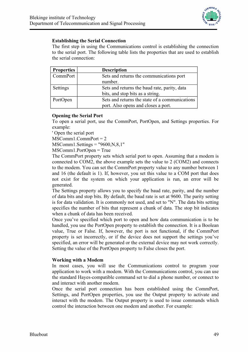
Establishing the Serial Connection The first step in using the Communications control is establishing the connection to the serial port. The following table lists the properties that are used to establish the serial connection: Properties Description CommPort Sets and returns the communications port
number. Settings Sets and returns the baud rate, parity, data
bits, and stop bits as a string. PortOpen Sets and returns the state of a communications
port. Also opens and closes a port.
Opening the Serial Port To open a serial port, use the CommPort, PortOpen, and Settings properties. For example: ' Open the serial port MSComm1.CommPort = 2 MSComm1.Settings = "9600,N,8,1" MSComm1.PortOpen = True The CommPort property sets which serial port to open. Assuming that a modem is connected to COM2, the above example sets the value to 2 (COM2) and connects to the modem. You can set the CommPort property value to any number between 1 and 16 (the default is 1). If, however, you set this value to a COM port that does not exist for the system on which your application is run, an error will be generated. The Settings property allows you to specify the baud rate, parity, and the number of data bits and stop bits. By default, the baud rate is set at 9600. The parity setting is for data validation. It is commonly not used, and set to "N". The data bits setting specifies the number of bits that represent a chunk of data. The stop bit indicates when a chunk of data has been received. Once you’ve specified which port to open and how data communication is to be handled, you use the PortOpen property to establish the connection. It is a Boolean value, True or False. If, however, the port is not functional, if the CommPort property is set incorrectly, or if the device does not support the settings you’ve specified, an error will be generated or the external device may not work correctly. Setting the value of the PortOpen property to False closes the port.
Working with a Modem In most cases, you will use the Communications control to program your application to work with a modem. With the Communications control, you can use the standard Hayes-compatible command set to dial a phone number, or connect to and interact with another modem. Once the serial port connection has been established using the CommPort, Settings, and PortOpen properties, you use the Output property to activate and interact with the modem. The Output property is used to issue commands which control the interaction between one modem and another. For example:

Blekinge institute of Technology Department of Telecommunication and Signal Processing
Blueboat 50
' Activate the modem and dial a phone number. MSComm1.Output = "ATDT 555-5555" & vbCr In the example above, the command "AT" initiates the connection, "D" dials the number, and "T" specifies touch tone (rather than pulse). A carriage return character (vbCr) must be specified when outputting to a terminal. You do not need to add the return character when outputting byte arrays. When a command is successfully processed, an "OK" result code will be returned. You can test for this result code to determine if a command was processed successfully. For More Information For a complete list of Hayes-compatible commands, check your modem documentation.
Setting Receive and Transmit Buffer Properties at Design Time When a port is opened, receive and transmit buffers are created. To manage these buffers, the Communications control provides you with a number of properties that can be set at design time using the control’s Property Pages. Setting buffer properties at design time
Buffer Memory Allocation The InBufferSize and OutBufferSize properties specify how much memory is allocated to the receive and transmit buffers. Each are set by default to the values shown above. The larger you make the number, the less memory you have available to your application. If, however, your buffer is too small, you run the risk of overflowing the buffer unless you use handshaking. Note Given the amount of memory available to most PCs at this time, buffer memory allocation is less crucial because you have more resources available. In other words, you can set the buffer values higher without affecting the performance of your application.
The RThreshold and SThreshold Properties The RThreshold and SThreshold properties set or return the number of characters that are received into the receive and transmit buffers before the OnComm event is

Blekinge institute of Technology Department of Telecommunication and Signal Processing
Blueboat 51
fired. The OnComm event is used to monitor and respond to changes in communications states. Setting the value for each property to zero (0) prevents the OnComm event from firing. Setting the value to something other than 0 (1, for instance) causes the OnComm event to be fired every time a single character is received into either buffer. For More Information See "The OnComm Event and the CommEvent Property" in this topic for more information on these properties.
The InputLen and EOFEnable Properties Setting the InputLen property to 0 causes the Communications control to read the entire contents of the receive buffer when the Input property is used. When reading data from a machine whose output is formatted in fixed-length blocks of data, the value of this property can be set appropriately. The EOFEnable property is used to indicate when an End of File (EOF) character is found during data input. Setting this to True causes data input to stop and the OnComm event to fire to inform you that this condition has occurred. For More Information See "Managing the Receive and Transmit Buffers" and "The OnComm Event and the CommEvent Property" in this topic for more information.
Managing the Receive and Transmit Buffers As mentioned above, receive and transmit buffers are created whenever a port is opened. The receive and transmit buffers are used to store incoming data and to transmit outgoing data. The Communications control allows you to manage these buffers by providing you with a number of properties that are used to place and retrieve data, return the size of each buffer, and handle both text and binary data. Properly managing these buffers is an important part of using the Communications control.
The Receive Buffer The Input property is used to store and retrieve data from the receive buffer. For example, if you wanted to retrieve data from the receive buffer and display it in a text box, you might use the following code: txtDisplay.Text = MSComm1.Input To retrieve the entire contents of the receive buffer, however, you must first set the InputLen property to 0. This can be done at design or run time. You can also receive incoming data as either text or binary data by setting the InputMode property to one of the following Visual Basic constants: comInputModeText or comInputModeBinary. The data will either be retrieved as string or as binary data in a Byte array. Use comInputModeText for data that uses the ANSI character set and comInputModeBinary for all other data, such as data that has embedded control characters, Nulls, etc. As each byte of data is received, it is moved into the receive buffer and the InBufferCount property is incremented by one. The InBufferCount property, then, can be used to retrieve the number of bytes in the receive buffer. You can also clear the receive buffer by setting the value of this property to 0.
The Transmit Buffer The Output property is used to send commands and data to the transmit buffer.

Blekinge institute of Technology Department of Telecommunication and Signal Processing
Blueboat 52
Like the Input property, data can be transmitted as either text or binary data. The Output property, however, must transmit either text or binary data by specifying either a string or Byte array variant. You can send commands, text strings, or Byte array data with the Output property. For example:
' Send an AT command MSComm1.Output = "ATDT 555-5555" ' Send a text string MsComm1.Output = "This is a text string" ' Send Byte array data MSComm1.Output = Out As previously mentioned, transmit lines must end with a carriage return character (vbCr). In the last example, Out is a variable defined as a Byte array: Dim Out() As Byte. If it were a string variant, it would be defined as: Dim Out() As String. You can monitor the number of bytes in the transmit buffer by using the OutBufferCount property. You can clear the transmit buffer by setting this value to 0.
Handshaking An integral part of managing the receive and transmit buffers is ensuring that the back-and-forth transmission of data is successful — that the speed at which the data is being received does not overflow the buffer limits, for example. Handshaking refers to the internal communications protocol by which data is transferred from the hardware port to the receive buffer. When a character of data arrives at the serial port, the communications device has to move it into the receive buffer so that your program can read it. A handshaking protocol ensures that data is not lost due to a buffer overrun, where data arrives at the port too quickly for the communications device to move the data into the receive buffer. You set the Handshaking property to specify the handshaking protocol to be used by your application. By default, this value is set to none (comNone). You can, however, specify one of the other following protocols:
Setting Value Description comNone 0 No handshaking (Default).
comXOnXOff 1 XOn/XOff handshaking.
comRTS 2 RTS/CTS (Request To Send/Clear To Send) handshaking.
comRTSXOnXOff 3 Both Request To Send and XOn/XOff handshaking.
The protocol that you choose depends upon the device to which you’re connecting. Setting this value to comRTSXOnXOff supports both of the protocols. In many cases, the communications protocol itself handles handshaking. Therefore, setting this property to something other than comNone may result in conflicts.
Note If you do set this value to either comRTS or comRTSXOnXOff, you need to set the RTSEnabled property to True. Otherwise, you will be able to connect

Blekinge institute of Technology Department of Telecommunication and Signal Processing
Blueboat 53
and send, but not receive, data. The OnComm Event and the CommEvent Property Depending upon the scope and functionality of your application, you may need to monitor and respond to any number of events or errors which may occur during the connection to another device or in the receipt or transmission of data. The OnComm event and the CommEvent property allow you to trap and check the value of communication events and errors. When a communication event or error occurs, the OnComm event is fired and the value of the CommEvent property is changed. Therefore, if necessary, you can check the value of the CommEvent property each time the OnComm event is fired. Because communications (especially over telephone lines) can be unpredictable, trapping these events and errors allows you to respond to them appropriately. The following table lists the communication events that will trigger the OnComm event. The values will then be written to the CommEvent property.
Constant Value Description
comEvSend 1 There are fewer than SThreshold number of characters in the transmit buffer.
comEvReceive 2
Received RThreshold number of characters. This event is generated continuously until you use the Input property to remove the data from the receive buffer.
comEvCTS 3 Change in Clear To Send line.
comEvDSR 4 Change in Data Set Ready line. This event is only fired when DSR changes from 1 to 0.
comEvCD 5 Change in Carrier Detect line.
comEvRing 6 Ring detected. Some UARTs (universal asynchronous receiver-transmitters) may not support this event.
comEvEOF 7 End Of File (ASCII character 26) character received.
The OnComm event is also triggered, and a value is written to the CommEvent property, when the following errors are encountered.
Setting Value Description comEventBreak 1001 A Break signal was received.
comEventFrame 1004 Framing Error. The hardware detected a framing error.
comEventOverrun 1006 Port Overrun. A character was not read from the hardware before the next character arrived and was lost.
comEventRxOver 1008 Receive Buffer Overflow. There is no room in the receive buffer.

Blekinge institute of Technology Department of Telecommunication and Signal Processing
Blueboat 54
comEventRxParity 1009 Parity Error. The hardware detected a parity error.
comEventTxFull 1010 Transmit Buffer Full. The transmit buffer was full while trying to queue a character.
comEventDCB 1011 Unexpected error retrieving Device Control Block (DCB) for the port.

Blekinge institute of Technology Department of Telecommunication and Signal Processing
Blueboat 55
10 Appendix – MCU Program AVR 128 This is the program loaded into the ATMEL128. The MCU has one connection to the Data panel (UART0) and one connection to a Bluetooth unit (UART1)
//ICC-AVR application builder : 2002-04-28 18:18:55 // Target : M128 // Crystal: 3.6864Mhz #include <iom128v.h> #include <macros.h> #include "init.h" static unsigned int InitializationCommandCnt = 0; static unsigned int SendLengthCnt = 0; unsigned char reset[4] = {0x01,0x03,0x0C,0x00}; unsigned char writeScanEnable[5] = {0x01,0x1A,0x0C,0x01,0x03}; unsigned char setEventFilter[7] = {0x01,0x05,0x0C,0x03,0x02,0x00,0x02}; unsigned char changeLocalName[252] = {0}; unsigned char ConnectionID; static unsigned char ReadData[20]= {0}; char incommingData[150] = {0}; static unsigned int ReadLengthCnt = 0; static unsigned int incommingDataCnt = 0; static unsigned int pktCnt = 0; static unsigned int ReadDataLength = 0; typedef enum {UNCONNECTED, CONNECTED} BTstatus; BTstatus ourBT = UNCONNECTED; #pragma interrupt_handler uart0_rx_isr:19 void uart0_rx_isr(void) { int i = 0; ReadData[ReadLengthCnt++] = UDR0; if (ReadLengthCnt == 3)//om vi har kommit till platsen för storleken på paketet { ReadDataLength = (int)ReadData[2]; //läs in storleken och lägg i readdatalength } if (ReadLengthCnt == (3+ReadDataLength)) /*Då är paketet färdiginläst */ { if (ReadData[1] == 0x05 && ReadData[3] == 0x00)//disonnection complete OCH ok { BTstatus ourBT = UNCONNECTED; PORTB = 0b11111110; } else if (ReadData[1] == 0x03 && ReadData[3] == 0x00) //connection complete OCH OK { BTstatus ourBT = CONNECTED; ConnectionID = ReadData[4]; PORTB = 0b01111111; }

Blekinge institute of Technology Department of Telecommunication and Signal Processing
Blueboat 56
else if (ReadData[1] == 0x0E && ReadData[6] == 0x00) //tex reset eller writescan OK { PORTB = 0b01010101; } ReadLengthCnt=0; } } void sendAcl(char *data, int dataLangd) //datan och hur mycket { int i = 0; int Totalstorlek = dataLangd + 4; unsigned char ACLpkt[150] = {0}; ACLpkt[0]=0x02; //ACL-pkt ACLpkt[1]=ConnectionID; //connectionID, om ej överstiger 8 bitars storlek ACLpkt[2]=0x20; //hci-acl header ACLpkt[3]=Totalstorlek; //datalängd(utan huvud) ACLpkt[4]=0x00; //datalängd(utan huvud) ACLpkt[5]=dataLangd; //datastorlek (storlek på rådata) ACLpkt[6]=0x00; //datastorlek (storlek på rådata) ACLpkt[7]=0x00; //l2cap applikationsnr. ACLpkt[8]=0x00; //l2cap applikationsnr. for(i=0;i<dataLangd;i++) //packa i rådata i resten av paketet { ACLpkt[i+9] = data[i]; } i=0; while (i<Totalstorlek+5) { USART0_Transmit(ACLpkt[i]); i++; } } #pragma interrupt_handler uart0_tx_isr:21 void uart0_tx_isr(void) { //character has been transmitted } #pragma interrupt_handler uart1_rx_isr:31 //recieve data from USART1 and send it to Bluetooth unit //size of data = j //the data is put in the array incomingData void uart1_rx_isr(void) { incommingData[incommingDataCnt++] = UDR1; PORTB = incommingData[incommingDataCnt]; if (incommingData[0] == 0x10 && incommingData[1] == 0x02) { pktCnt++; if (incommingData[incommingDataCnt-2] == 0x10 && incommingData[incommingDataCnt-1] == 0x03) { sendAcl(incommingData,pktCnt);
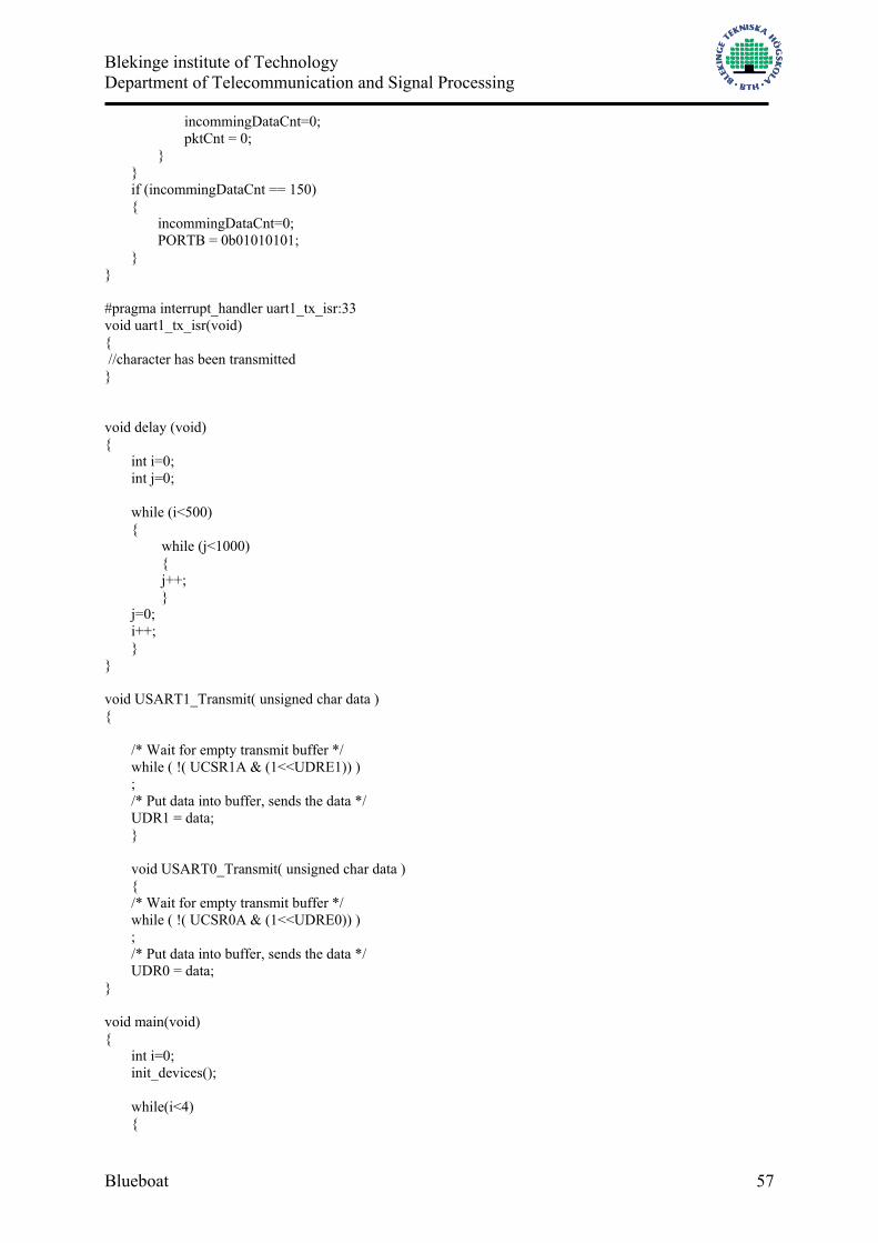
Blekinge institute of Technology Department of Telecommunication and Signal Processing
Blueboat 57
incommingDataCnt=0; pktCnt = 0; } } if (incommingDataCnt == 150) { incommingDataCnt=0; PORTB = 0b01010101; } } #pragma interrupt_handler uart1_tx_isr:33 void uart1_tx_isr(void) { //character has been transmitted } void delay (void) { int i=0; int j=0; while (i<500) { while (j<1000) { j++; } j=0; i++; } } void USART1_Transmit( unsigned char data ) { /* Wait for empty transmit buffer */ while ( !( UCSR1A & (1<<UDRE1)) ) ; /* Put data into buffer, sends the data */ UDR1 = data; } void USART0_Transmit( unsigned char data ) { /* Wait for empty transmit buffer */ while ( !( UCSR0A & (1<<UDRE0)) ) ; /* Put data into buffer, sends the data */ UDR0 = data; } void main(void) { int i=0; init_devices(); while(i<4) {
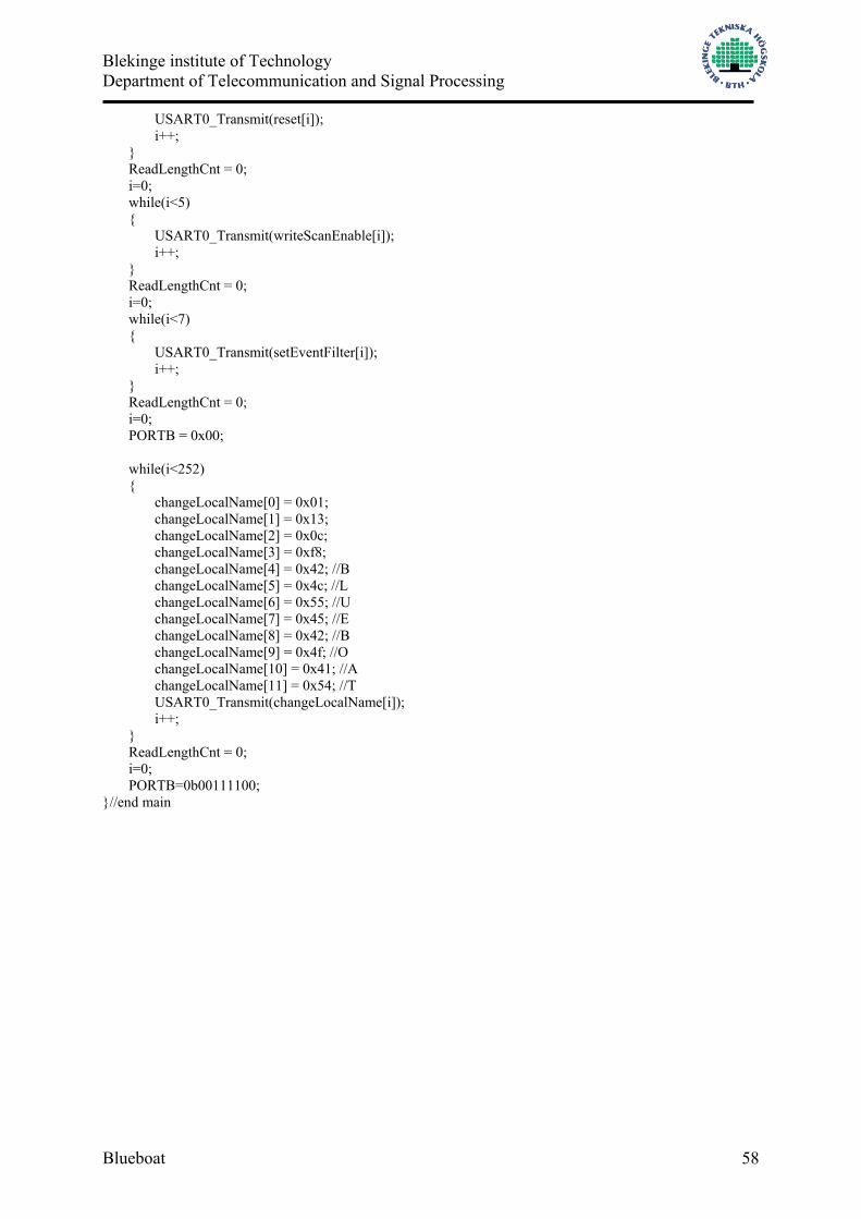
Blekinge institute of Technology Department of Telecommunication and Signal Processing
Blueboat 58
USART0_Transmit(reset[i]); i++; } ReadLengthCnt = 0; i=0; while(i<5) { USART0_Transmit(writeScanEnable[i]); i++; } ReadLengthCnt = 0; i=0; while(i<7) { USART0_Transmit(setEventFilter[i]); i++; } ReadLengthCnt = 0; i=0; PORTB = 0x00; while(i<252) { changeLocalName[0] = 0x01; changeLocalName[1] = 0x13; changeLocalName[2] = 0x0c; changeLocalName[3] = 0xf8; changeLocalName[4] = 0x42; //B changeLocalName[5] = 0x4c; //L changeLocalName[6] = 0x55; //U changeLocalName[7] = 0x45; //E changeLocalName[8] = 0x42; //B changeLocalName[9] = 0x4f; //O changeLocalName[10] = 0x41; //A changeLocalName[11] = 0x54; //T USART0_Transmit(changeLocalName[i]); i++; } ReadLengthCnt = 0; i=0; PORTB=0b00111100; }//end main

Blekinge institute of Technology Department of Telecommunication and Signal Processing
Blueboat 59
11 Appendix – Bluetooth commands HCI reset: 01030c00 write scan enable: 011a0c0103 SetEventFilter: 01050c03020002 SetEventFilter: 01050c020000 readlocalname: 01140C00 inquiry: 01010405338b9e0900 aclpkt: 0201208000040001004f4c4120 remoteNameRequest 0119040a1f8c1637800000000000 disconnect 01060403010013 readownbdaddress 01091000 readFailedContactCounter 010114020100(connectionhandle = 1) readlinkquality 010314020100(connectionhandle = 1) SendData 0201200A0006000000123456789012 change local name:(AAA): 01130cf84141410000000000000000000000000000000000000000000000000000000000000000000000000000000000000000000000000000000000000000000000000000000000000000000000000000000000000000000000000000000000000000000000000000000000000000000000000000000000000000000000000000000000000000000000000000000000000000000000000000000000000000000000000000000000000000000000000000000000000000000000000000000000000000000000000000000000000000000000000000000000000000000000000000000000000000000000000000000000000000000000000000000000

Blekinge institute of Technology Department of Telecommunication and Signal Processing
Blueboat 60
12 Appendix – MSChart Example
The MSChart control supports the following features: True three-dimensional representation. Support for all major chart types. Data grid population via random data and data arrays. The MSChart control is associated with a data grid (DataGrid object). This data grid is a table that holds the data being charted. The data grid can also include labels used to identify series and categories on the chart. The person who designs your chart application fills the data grid with information by inserting data or by importing data from a spreadsheet or array. Example In this example, the sales for two companies are shown for four months. Create the data array and bind it to the ChartData property.
Dim Sales(,) As Object = New Object(, ) {{"Company", "Company A", "Company B"}, _ {"June", 20, 10}, _ {"July", 10, 5}, _ {"August", 30, 15}, _ {"September", 14, 7}} chtSales.ChartData = Sales 'Add a title and legend. With Me.chtSales .Title.Text = "Sales" .Legend.Location.LocationType = _ MSChart20Lib.VtChLocationType.VtChLocationTypeBottom .Legend.Location.Visible = True End With 'Add titles to the axes. With Me.chtSales.Plot .Axis(MSChart20Lib.VtChAxisId.VtChAxisIdX).AxisTitle.Text = "Year" .Axis(MSChart20Lib.VtChAxisId.VtChAxisIdY).AxisTitle.Text = "Millions of $" End With 'Set custom colors for the bars. With Me.chtSales.Plot 'Yellow for Company A ' -1 selects all the datapoints. .SeriesCollection(1).DataPoints(-1).Brush.FillColor.Set(250, 250, 0) 'Purple for Company B .SeriesCollection(2).DataPoints(-1).Brush.FillColor.Set(200, 50, 200) End With