Embed Size (px)
Citation preview
¤ 2014 Microchip Technology Inc. DS00001861A-page 1
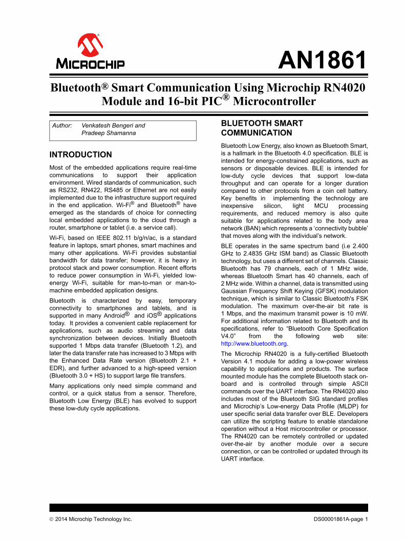
INTRODUCTIONMost of the embedded applications require real-timecommunications to support their applicationenvironment. Wired standards of communication, suchas RS232, RN422, RS485 or Ethernet are not easilyimplemented due to the infrastructure support requiredin the end application. Wi-Fi® and Bluetooth® haveemerged as the standards of choice for connectinglocal embedded applications to the cloud through arouter, smartphone or tablet (i.e. a service call).
Wi-Fi, based on IEEE 802.11 b/g/n/ac, is a standardfeature in laptops, smart phones, smart machines andmany other applications. Wi-Fi provides substantialbandwidth for data transfer; however, it is heavy inprotocol stack and power consumption. Recent effortsto reduce power consumption in Wi-Fi, yielded low-energy Wi-Fi, suitable for man-to-man or man-to-machine embedded application designs.
Bluetooth is characterized by easy, temporaryconnectivity to smartphones and tablets, and issupported in many Android® and iOS® applicationstoday. It provides a convenient cable replacement forapplications, such as audio streaming and datasynchronization between devices. Initially Bluetoothsupported 1 Mbps data transfer (Bluetooth 1.2), andlater the data transfer rate has increased to 3 Mbps withthe Enhanced Data Rate version (Bluetooth 2.1 +EDR), and further advanced to a high-speed version(Bluetooth 3.0 + HS) to support large file transfers.
Many applications only need simple command andcontrol, or a quick status from a sensor. Therefore,Bluetooth Low Energy (BLE) has evolved to supportthese low-duty cycle applications.
BLUETOOTH SMART COMMUNICATIONBluetooth Low Energy, also known as Bluetooth Smart,is a hallmark in the Bluetooth 4.0 specification. BLE isintended for energy-constrained applications, such assensors or disposable devices. BLE is intended forlow-duty cycle devices that support low-datathroughput and can operate for a longer durationcompared to other protocols from a coin cell battery.Key benefits in implementing the technology areinexpensive silicon, light MCU processingrequirements, and reduced memory is also quitesuitable for applications related to the body areanetwork (BAN) which represents a ‘connectivity bubble’that moves along with the individual’s network.
BLE operates in the same spectrum band (i.e 2.400GHz to 2.4835 GHz ISM band) as Classic Bluetoothtechnology, but uses a different set of channels. ClassicBluetooth has 79 channels, each of 1 MHz wide,whereas Bluetooth Smart has 40 channels, each of2 MHz wide. Within a channel, data is transmitted usingGaussian Frequency Shift Keying (GFSK) modulationtechnique, which is similar to Classic Bluetooth's FSKmodulation. The maximum over-the-air bit rate is1 Mbps, and the maximum transmit power is 10 mW.For additional information related to Bluetooth and itsspecifications, refer to “Bluetooth Core SpecificationV4.0” from the following web site:http://www.bluetooth.org.
The Microchip RN4020 is a fully-certified BluetoothVersion 4.1 module for adding a low-power wirelesscapability to applications and products. The surfacemounted module has the complete Bluetooth stack on-board and is controlled through simple ASCIIcommands over the UART interface. The RN4020 alsoincludes most of the Bluetooth SIG standard profilesand Microchip’s Low-energy Data Profile (MLDP) foruser specific serial data transfer over BLE. Developerscan utilize the scripting feature to enable standaloneoperation without a Host microcontroller or processor.The RN4020 can be remotely controlled or updatedover-the-air by another module over a secureconnection, or can be controlled or updated through itsUART interface.
Author: Venkatesh Bengeri and Pradeep Shamanna
AN1861Bluetooth® Smart Communication Using Microchip RN4020
Module and 16-bit PIC® Microcontroller
AN1861
DS00001861A-page 2 ¤ 2014 Microchip Technology Inc.
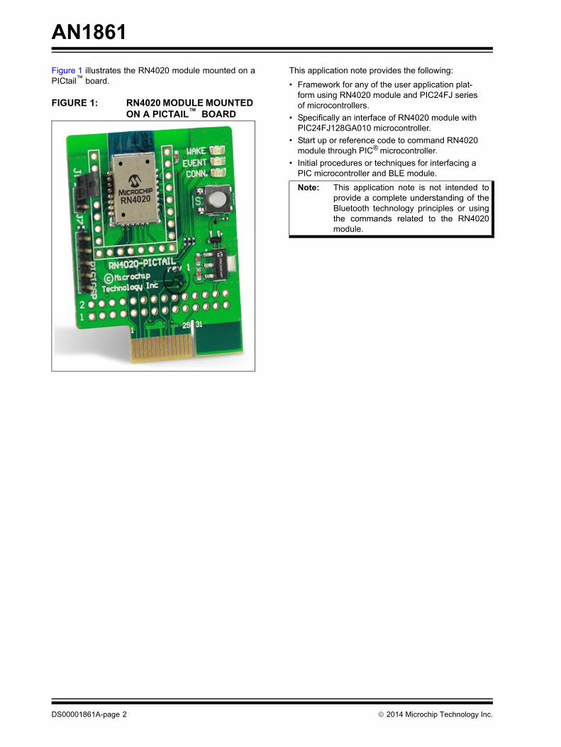
Figure 1 illustrates the RN4020 module mounted on aPICtail™ board.
FIGURE 1: RN4020 MODULE MOUNTED ON A PICTAIL™ BOARD
This application note provides the following:
• Framework for any of the user application plat-form using RN4020 module and PIC24FJ series of microcontrollers.
• Specifically an interface of RN4020 module with PIC24FJ128GA010 microcontroller.
• Start up or reference code to command RN4020 module through PIC® microcontroller.
• Initial procedures or techniques for interfacing a PIC microcontroller and BLE module.
Note: This application note is not intended toprovide a complete understanding of theBluetooth technology principles or usingthe commands related to the RN4020module.
¤ 2014 Microchip Technology Inc. DS00001861A-page 3
AN1861
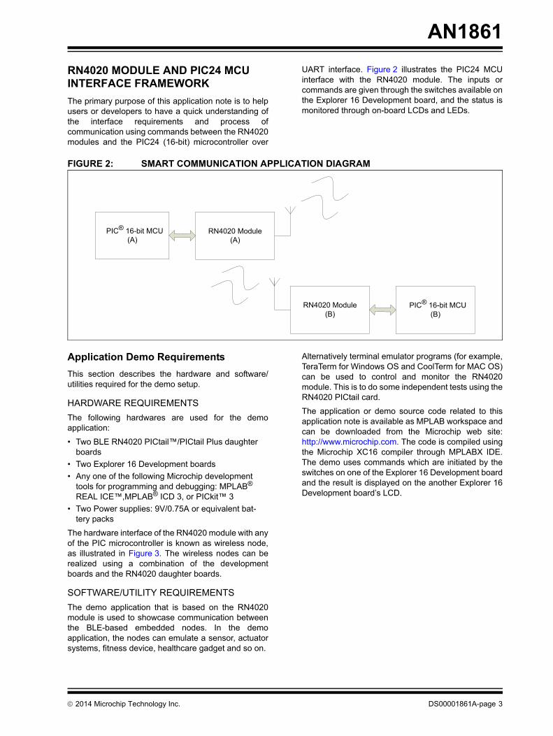
RN4020 MODULE AND PIC24 MCU INTERFACE FRAMEWORK The primary purpose of this application note is to helpusers or developers to have a quick understanding ofthe interface requirements and process ofcommunication using commands between the RN4020modules and the PIC24 (16-bit) microcontroller over
UART interface. Figure 2 illustrates the PIC24 MCUinterface with the RN4020 module. The inputs orcommands are given through the switches available onthe Explorer 16 Development board, and the status ismonitored through on-board LCDs and LEDs.
FIGURE 2: SMART COMMUNICATION APPLICATION DIAGRAM
Application Demo RequirementsThis section describes the hardware and software/utilities required for the demo setup.
HARDWARE REQUIREMENTSThe following hardwares are used for the demoapplication:
• Two BLE RN4020 PICtail™/PICtail Plus daughter boards
• Two Explorer 16 Development boards • Any one of the following Microchip development
tools for programming and debugging: MPLAB® REAL ICE™,MPLAB® ICD 3, or PICkit™ 3
• Two Power supplies: 9V/0.75A or equivalent bat-tery packs
The hardware interface of the RN4020 module with anyof the PIC microcontroller is known as wireless node,as illustrated in Figure 3. The wireless nodes can berealized using a combination of the developmentboards and the RN4020 daughter boards.
SOFTWARE/UTILITY REQUIREMENTSThe demo application that is based on the RN4020module is used to showcase communication betweenthe BLE-based embedded nodes. In the demoapplication, the nodes can emulate a sensor, actuatorsystems, fitness device, healthcare gadget and so on.
Alternatively terminal emulator programs (for example,TeraTerm for Windows OS and CoolTerm for MAC OS)can be used to control and monitor the RN4020module. This is to do some independent tests using theRN4020 PICtail card.
The application or demo source code related to thisapplication note is available as MPLAB workspace andcan be downloaded from the Microchip web site:http://www.microchip.com. The code is compiled usingthe Microchip XC16 compiler through MPLABX IDE.The demo uses commands which are initiated by theswitches on one of the Explorer 16 Development boardand the result is displayed on the another Explorer 16Development board’s LCD.
PIC® 16-bit MCU (A)
RN4020 Module(A)
RN4020 Module(B)
PIC® 16-bit MCU (B)
AN1861
DS00001861A-page 4 ¤ 2014 Microchip Technology Inc.
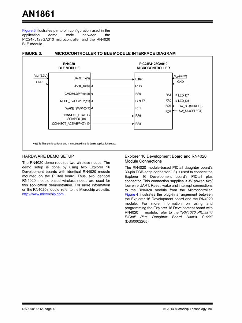
Figure 3 illustrates pin to pin configuration used in theapplication demo code between thePIC24FJ128GA010 microcontroller and the RN4020BLE module.
FIGURE 3: MICROCONTROLLER TO BLE MODULE INTERFACE DIAGRAM
HARDWARE DEMO SETUPThe RN4020 demo requires two wireless nodes. Thedemo setup is done by using two Explorer 16Development boards with identical RN4020 modulemounted on the PICtail board. Thus, two identicalRN4020 module-based wireless nodes are used forthis application demonstration. For more informationon the RN4020 module, refer to the Microchip web site:http://www.microchip.com.
Explorer 16 Development Board and RN4020 Module ConnectionsThe RN4020 module-based PICtail daughter board’s30-pin PCB-edge connector (J3) is used to connect theExplorer 16 Development board's PICtail plusconnector. This connection supplies 3.3V power, two/four wire UART, Reset, wake and interrupt connectionsto the RN4020 module from the Microcontroller.Figure 4 illustrates the plug-in arrangement betweenthe Explorer 16 Development board and the RN4020module. For more information on using andprogramming the Explorer 16 Development board withRN4020 module, refer to the “RN4020 PICtail™/PICtail Plus Daughter Board User’s Guide”(DS50002265).
RN4020BLE MODULE
PIC24FJ128GA010 MICROCONTROLLER
UART_Tx(5)
UART_Rx(6)
MLDP_EV/CS/PI02(11)
CMD/MLDP/PI04(8)
WAKE_SW/PI03(7)
CONNECT_STATUS/SCK/PI05 (10)
U1Rx
U1Tx
GPIO(1)
RF1
RF8
VDD (3.3V)
GND GND
CONNECT_ACTIVE/PI07 (19)
RF6
VDD (3.3V)
RA4
RA5
RD6
RD7 SW_S6 (SELECT)SW_S3 (SCROLL)
LED_D8
LED_D7RF0
Note 1: This pin is optional and it is not used in this demo application setup.
¤ 2014 Microchip Technology Inc. DS00001861A-page 5
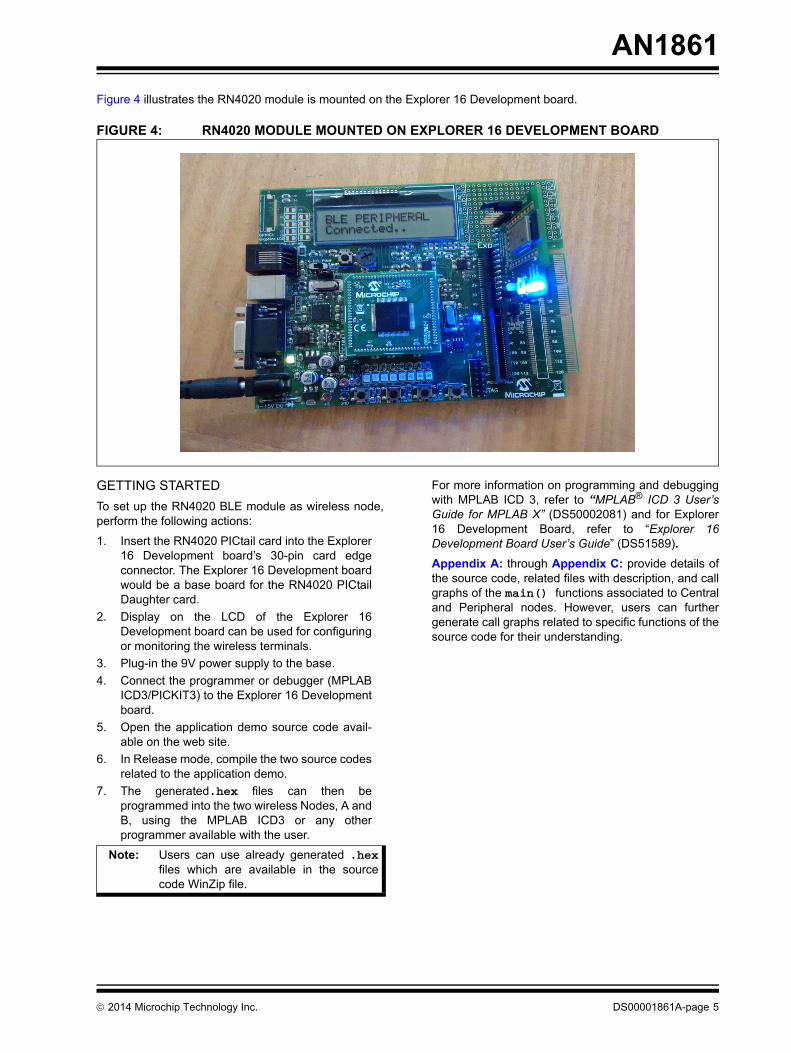
AN1861Figure 4 illustrates the RN4020 module is mounted on the Explorer 16 Development board.
FIGURE 4: RN4020 MODULE MOUNTED ON EXPLORER 16 DEVELOPMENT BOARD
GETTING STARTEDTo set up the RN4020 BLE module as wireless node,perform the following actions:
1. Insert the RN4020 PICtail card into the Explorer16 Development board’s 30-pin card edgeconnector. The Explorer 16 Development boardwould be a base board for the RN4020 PICtailDaughter card.
2. Display on the LCD of the Explorer 16Development board can be used for configuringor monitoring the wireless terminals.
3. Plug-in the 9V power supply to the base. 4. Connect the programmer or debugger (MPLAB
ICD3/PICKIT3) to the Explorer 16 Developmentboard.
5. Open the application demo source code avail-able on the web site.
6. In Release mode, compile the two source codesrelated to the application demo.
7. The generated.hex files can then beprogrammed into the two wireless Nodes, A andB, using the MPLAB ICD3 or any otherprogrammer available with the user.
For more information on programming and debuggingwith MPLAB ICD 3, refer to “MPLAB® ICD 3 User’sGuide for MPLAB X” (DS50002081) and for Explorer16 Development Board, refer to “Explorer 16Development Board User’s Guide” (DS51589).Appendix A: through Appendix C: provide details ofthe source code, related files with description, and callgraphs of the main() functions associated to Centraland Peripheral nodes. However, users can furthergenerate call graphs related to specific functions of thesource code for their understanding.
Note: Users can use already generated .hexfiles which are available in the sourcecode WinZip file.
AN1861
DS00001861A-page 6 ¤ 2014 Microchip Technology Inc.
RN4020 Demo ApplicationThe execution of the RN4020 demo applicationinvolves the following two steps:
1. Configuring one node as Central and anothernode as Peripheral.
2. Switch ON or OFF to toggle LEDs (D7 and D8)on the Node B when switches (S3 and S6) onthe Node A are pressed, and vice versa.
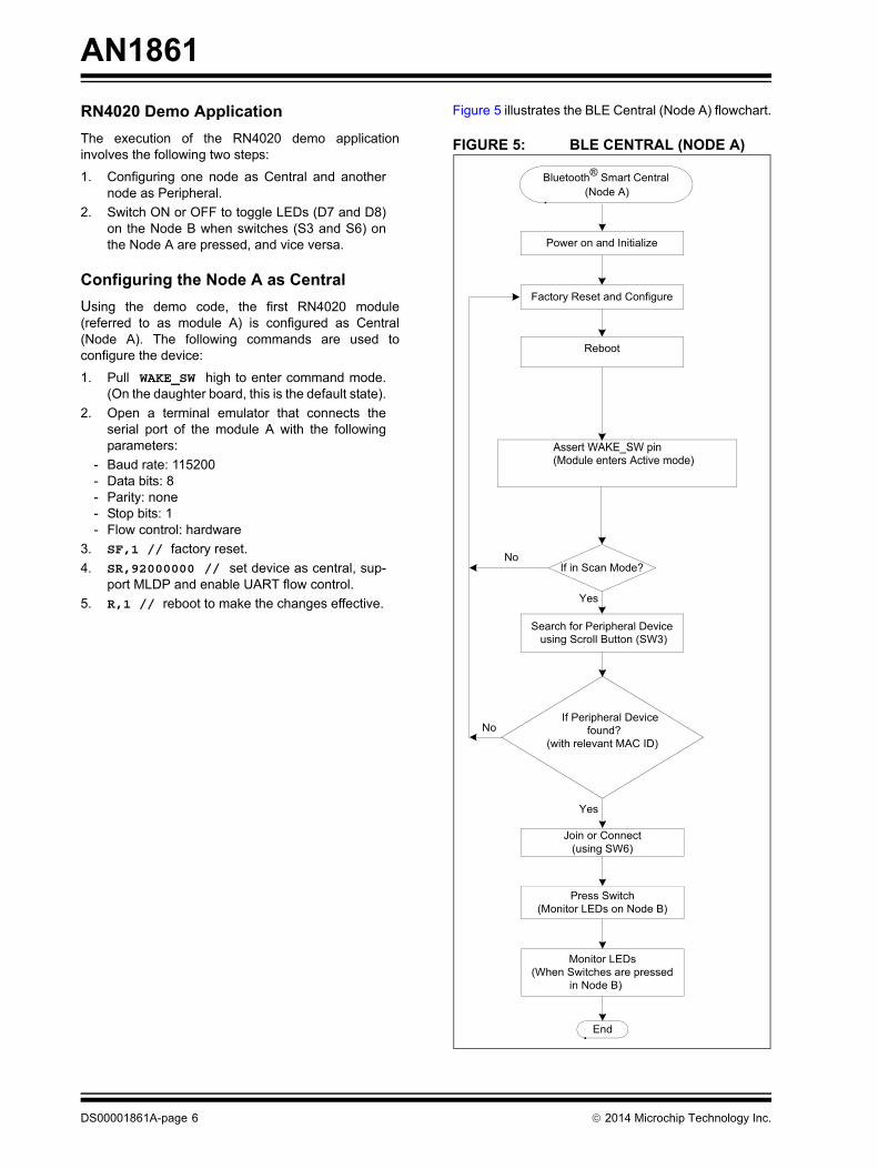
Configuring the Node A as CentralUsing the demo code, the first RN4020 module(referred to as module A) is configured as Central(Node A). The following commands are used toconfigure the device:
1. Pull WAKE_SW high to enter command mode.(On the daughter board, this is the default state).
2. Open a terminal emulator that connects theserial port of the module A with the followingparameters:
- Baud rate: 115200- Data bits: 8- Parity: none- Stop bits: 1- Flow control: hardware
3. SF,1 // factory reset.4. SR,92000000 // set device as central, sup-
port MLDP and enable UART flow control.5. R,1 // reboot to make the changes effective.
Figure 5 illustrates the BLE Central (Node A) flowchart.
FIGURE 5: BLE CENTRAL (NODE A)
Bluetooth® Smart Central (Node A)
Power on and Initialize
Factory Reset and Configure
Reboot
If in Scan Mode?
Search for Peripheral Device using Scroll Button (SW3)
Yes
Join or Connect(using SW6)
Press Switch(Monitor LEDs on Node B)
No
End
Monitor LEDs(When Switches are pressed
in Node B)
No If Peripheral Device
found?(with relevant MAC ID)
Yes
Assert WAKE_SW pin(Module enters Active mode)
¤ 2014 Microchip Technology Inc. DS00001861A-page 7
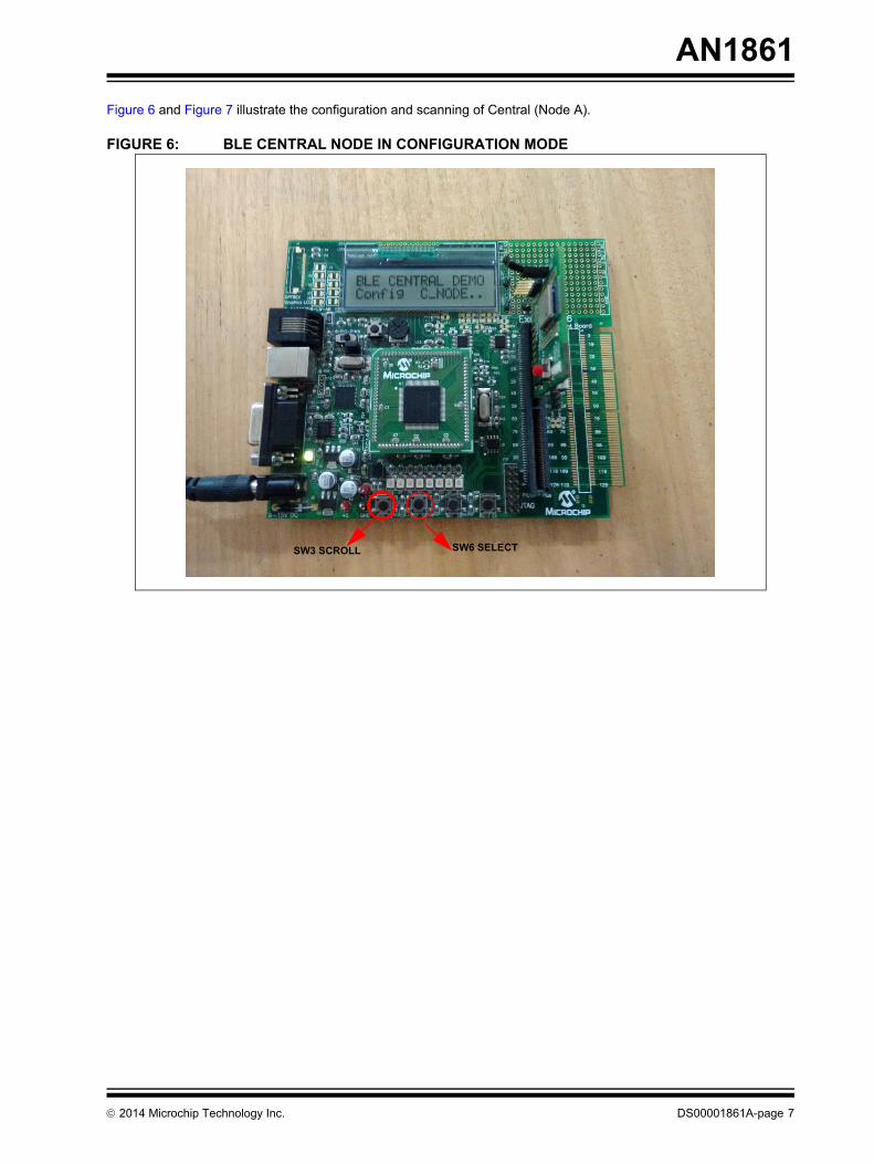
AN1861Figure 6 and Figure 7 illustrate the configuration and scanning of Central (Node A).
FIGURE 6: BLE CENTRAL NODE IN CONFIGURATION MODE
SW3 SCROLL SW6 SELECT
AN1861
DS00001861A-page 8 ¤ 2014 Microchip Technology Inc.
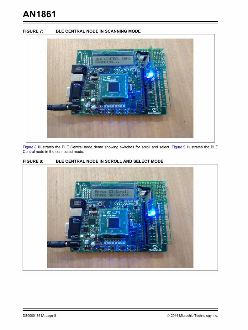
FIGURE 7: BLE CENTRAL NODE IN SCANNING MODE
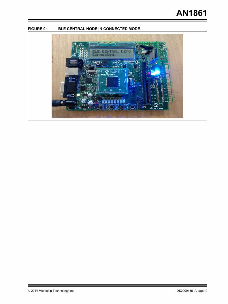
Figure 8 illustrates the BLE Central node demo showing switches for scroll and select. Figure 9 illustrates the BLECentral node in the connected mode.
FIGURE 8: BLE CENTRAL NODE IN SCROLL AND SELECT MODE
¤ 2014 Microchip Technology Inc. DS00001861A-page 9
AN1861FIGURE 9: BLE CENTRAL NODE IN CONNECTED MODE
AN1861
DS00001861A-page 10 ¤ 2014 Microchip Technology Inc.
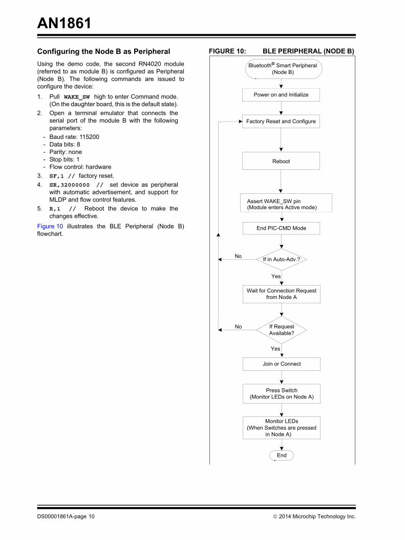
Configuring the Node B as PeripheralUsing the demo code, the second RN4020 module(referred to as module B) is configured as Peripheral(Node B). The following commands are issued toconfigure the device:
1. Pull WAKE_SW high to enter Command mode.(On the daughter board, this is the default state).
2. Open a terminal emulator that connects theserial port of the module B with the followingparameters:
- Baud rate: 115200- Data bits: 8- Parity: none- Stop bits: 1- Flow control: hardware
3. SF,1 // factory reset.4. SR,32000000 // set device as peripheral
with automatic advertisement, and support forMLDP and flow control features.
5. R,1 // Reboot the device to make thechanges effective.
Figure 10 illustrates the BLE Peripheral (Node B)flowchart.
FIGURE 10: BLE PERIPHERAL (NODE B)
Bluetooth® Smart Peripheral (Node B)
Power on and Initialize
Factory Reset and Configure
Reboot
End PIC-CMD Mode
If in Auto-Adv.?
Wait for Connection Request from Node A
Yes
Join or Connect
Press Switch(Monitor LEDs on Node A)
No
End
If Request Available?
Monitor LEDs(When Switches are pressed
in Node A)
No
Yes
Assert WAKE_SW pin(Module enters Active mode)
¤ 2014 Microchip Technology Inc. DS00001861A-page 11
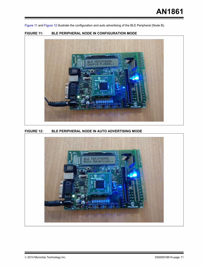
AN1861Figure 11 and Figure 12 illustrate the configuration and auto advertising of the BLE Peripheral (Node B).
FIGURE 11: BLE PERIPHERAL NODE IN CONFIGURATION MODE
FIGURE 12: BLE PERIPHERAL NODE IN AUTO ADVERTISING MODE
AN1861
DS00001861A-page 12 ¤ 2014 Microchip Technology Inc.
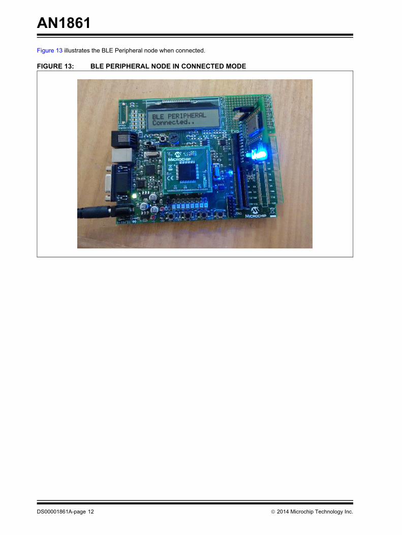
Figure 13 illustrates the BLE Peripheral node when connected.
FIGURE 13: BLE PERIPHERAL NODE IN CONNECTED MODE
¤ 2014 Microchip Technology Inc. DS00001861A-page 13
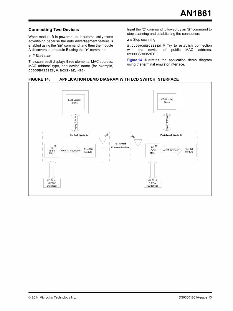
AN1861Connecting Two DevicesWhen module B is powered up, it automatically startsadvertising because the auto advertisement feature isenabled using the “SR” command, and then the moduleA discovers the module B using the “F” command:
F // Start scan
The scan result displays three elements: MAC address,MAC address type, and device name (for example,00035B0358E6,0,MCHP-LE,-50).
Input the “X” command followed by an “E” command tostop scanning and establishing the connection:
X // Stop scanning
E,0,00035B0358E6 // Try to establish connectionwith the device of public MAC address,0x00035B0358E6.
Figure 14 illustrates the application demo diagramusing the terminal emulator interface.
FIGURE 14: APPLICATION DEMO DIAGRAM WITH LCD SWITCH INTERFACE
Central (Node A)
PIC® 16-Bit
MCU
RN4020ModuleUART1 Interface
BT SmartCommunication
Peripheral (Node B)
PIC® 16-Bit
MCU
RN4020Module
UART1 Interface
LCD Display Block
Dis
play
Inte
rface
LCD Display Block
Dis
play
Inte
rface
I/O Block(LEDs/
Switches)
I/O Block(LEDs/
Switches)
AN1861
DS00001861A-page 14 ¤ 2014 Microchip Technology Inc.
MLDP Mode DetailsMLDP mode is entered by setting the CMD/MLDP pinhigh, all data from the UART is sent to the peer deviceas a data stream. To exit MLDP mode, the CMD/MLDPpin must be set low so that the RN4020 module isreturned to Command mode by outputting “CMD” to theUART. The CMD/MLDP pin (pin 8) is used to control theRN4020 module when an MLDP serial data service isused. For more information on MLDP Commands,refer to “RN4020 Bluetooth Low Energy Module User’sGuide” (DS70005191).
After the access and characteristics in public servicesare verified, the MLDP service can be started. TheMLDP service is built on top of the private service, butacts transparently by routing binary data read and writeto a private characteristic through the UART. To use theMLDP service between two RN4020 devices, both thedevices must enable MLDP with the “SR” command.The MLDP mode can only be started when twoRN4020 modules are MLDP-enabled and areconnected to each other. To start MLDP mode, performthe following actions:
1. Assert the CMD/MLDP pin to be high. TheRN4020 module will acknowledge with “MLDP”string to indicate the start of the MLDP mode.
2. Once in the MLDP mode, any data from theUART will be sent to the peer device.
3. While receiving the MLDP data from the peer, ifthe AUTO_MLDP_DISABLE feature is disabled,the RN4020 module will automatically enter theMLDP mode; otherwise, all data will be ignoreduntil the CMD/MLDP pin is set high to enterMLDP mode.
4. From the module A, assert the CMD/MLDP pinto be high and wait until “MLDP” is output to theUART. Provided module B shows “MLDP”,anything typed on the UART of the module A willbe displayed on the UART of the module B, andvice versa.
5. Set the CMD/MLDP pin to be low on module B(WAKE_HW and CMD/MLDP pins have weakpull down resistors hence they will stay low if notpulled high).
6. On module A, the status change will be notifiedto the Host. However, module A is currently inMLDP mode and only output MLDP data is sentto the UART. Instead, PIO2 will be set high (thered LED (MLDP_EV) illuminates on the RN4020PICtail Board) to indicate the pending statusmessage to be sent over the UART to the Hostmicrocontroller.
7. Once the CMD/MLDP pin is set low to entercommand mode, the status message will be out-put to the UART. The maximum status messagethat can be buffered is 256 bytes.
Note: To exit MLDP mode, set the CMD/MLDPpin to be low and the module willacknowledge with the “CMD” string, whichappears on the UART indicating that theRN4020 module is back in commandmode. A Host microcontroller is requiredto interpret the command and responsesavailable on the UART of the modules.
¤ 2014 Microchip Technology Inc. DS00001861A-page 15
AN1861Running the DemoAs mentioned earlier, configure one node as Peripheraland another node as Central as required by the BLEplatform for communication. Use the followingprocedure to program, connect, and test two wirelessBLE nodes.
1. Program one board with the BLE_Periph-eral.X.production.hex file and anotherboard with the BLE_Central.X.produc-tion.hex file.
2. After two boards are programmed, the Periph-eral device will be in the Auto-Advertising modeand the Central device will be in Scan mode.
3. The Central node has a LCD for monitoring andtwo switches for scrolling and selecting.
4. Scroll for the specific Peripheral node from theCentral node using the switch SW3.
5. Select the Peripheral node using the switchSW6.
6. Upon selection, the Peripheral node will connectto the Central node and the green (CONN) LEDon the RN4020 PICtail board turns ON, whichindicates the connection.
7. The modules then switch to the MLDP mode.8. Press the switch S3 or S6 from the Peripheral
node or Central node. The LED D9 or D10toggle on the Central or Peripheral node.
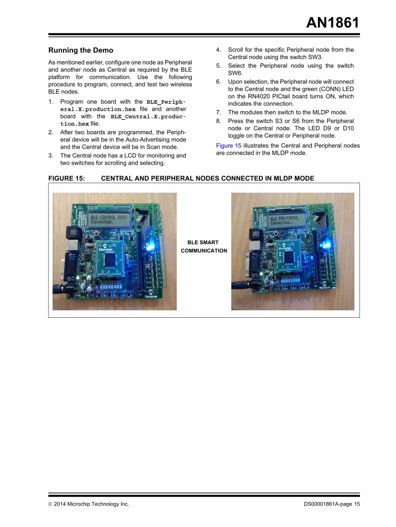
Figure 15 illustrates the Central and Peripheral nodesare connected in the MLDP mode.
FIGURE 15: CENTRAL AND PERIPHERAL NODES CONNECTED IN MLDP MODE
BLE SMART COMMUNICATION

AN1861
DS00001861A-page 16 ¤ 2014 Microchip Technology Inc.
NOTES:
¤ 2014 Microchip Technology Inc. DS00001861A-page 17
AN1861
APPENDIX A: SOURCE CODE
All of the software covered in this application note isavailable as a single WinZip archive file. This archivecan be downloaded from the Microchip corporate website at: www.microchip.com
Software License Agreement
The software supplied herewith by Microchip Technology Incorporated (the “Company”) is intended and supplied to you, theCompany’s customer, for use solely and exclusively with products manufactured by the Company.The software is owned by the Company and/or its supplier, and is protected under applicable copyright laws. All rights are reserved.Any use in violation of the foregoing restrictions may subject the user to criminal sanctions under applicable laws, as well as to civilliability for the breach of the terms and conditions of this license.THIS SOFTWARE IS PROVIDED IN AN “AS IS” CONDITION. NO WARRANTIES, WHETHER EXPRESS, IMPLIED ORSTATUTORY, INCLUDING, BUT NOT LIMITED TO, IMPLIED WARRANTIES OF MERCHANTABILITY AND FITNESS FOR APARTICULAR PURPOSE APPLY TO THIS SOFTWARE. THE COMPANY SHALL NOT, IN ANY CIRCUMSTANCES, BE LIABLEFOR SPECIAL, INCIDENTAL OR CONSEQUENTIAL DAMAGES, FOR ANY REASON WHATSOEVER.
AN1861
DS00001861A-page 18 ¤ 2014 Microchip Technology Inc.
APPENDIX B: SOURCE CODE FILE LIST
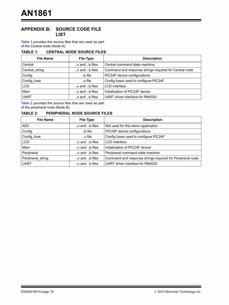
Table 1 provides the source files that are used as partof the Central node (Node A).
Table 2 provides the source files that are used as partof the peripheral node (Node B).
TABLE 1: CENTRAL NODE SOURCE FILESFile Name File Type Description
Central .c and .h files Central command state machineCentral_string .c and .h files Command and response strings required for Central nodeConfig .h file PIC24F device configurationsConfig_fuse .c file Config fuses used to configure PIC24FLCD .c and .h files LCD interfaceMain .c and .h files Initialization of PIC24F deviceUART .c and .h files UART driver interface for RN4020
TABLE 2: PERIPHERAL NODE SOURCE FILESFile Name File Type Description
ADC .c and .h files Not used for this demo applicationConfig .h file PIC24F device configurationsConfig_fuse .c file Config fuses used to configure PIC24FLCD .c and .h files LCD interfaceMain .c and .h files Initialization of PIC24F devicePeripheral .c and .h files Peripheral command state machinePeripheral_string .c and .h files Command and response strings required for Peripheral nodeUART .c and .h files UART driver interface for RN4020
¤ 2014 M
icrochip Technology Inc.D
S00001861A-page 19
AN
1861
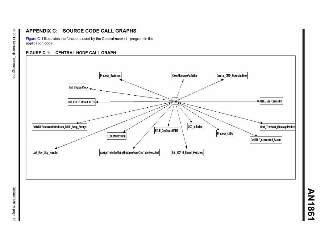
APPENDIX C: SOURCE CODE CALL GRAPHSFigure C-1 illustrates the functions used by the Central main() program in theapplication code.
FIGURE C-1: CENTRAL NODE CALL GRAPH
AN
1861
DS
00001861A-page 20
¤ 2014 M
icrochip Technology Inc.
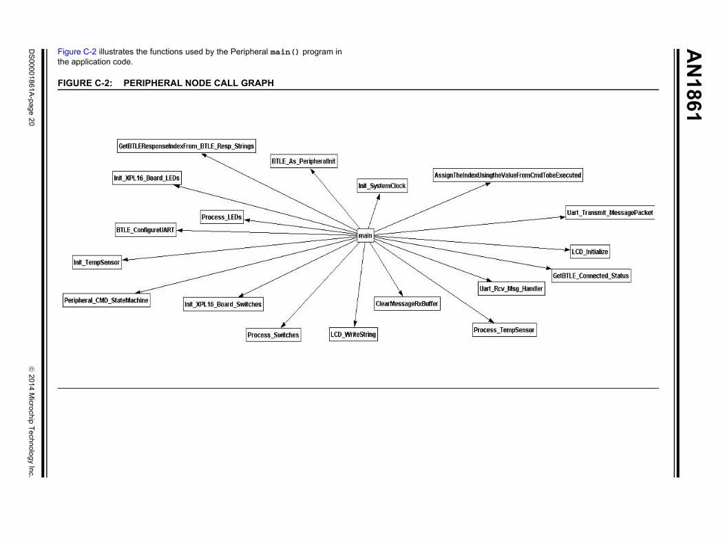
Figure C-2 illustrates the functions used by the Peripheral main() program inthe application code.
FIGURE C-2: PERIPHERAL NODE CALL GRAPH
¤ 2014 Microchip Technology Inc. DS00001861A-page 21
AN1861
APPENDIX D: REFERENCED SOURCES
This appendix provides information on the list ofresources that are referenced in this application note.
Microchip Technology Inc. Resources• “RN4020 Bluetooth Low Energy Module Data
Sheet” (DS50002279)• “RN4020 Bluetooth Low Energy Module User’s
Guide” (DS70005191)• “RN4020 PICtail™/PICtail Plus Board User’s
Guide” (DS50002265)• “Explorer 16 Development Board User’s Guide”
(DS50001589)• “PIC24FJ128GA010 Family Data sheet”
(DS39747F)• “MPLAB ICD 3 USER’S GUIDE FOR MPLAB X
IDE” (DS50002081)
Other Resources• Bluetooth Core Specification 4.1 Adopted
Documents: https://www.bluetooth.org/en-us/specification/adopted-specifications
• Bluetooth 4.1 GATT Definitions Browser: https://developer.bluetooth.org/gatt/Pages/Definition-Browser.aspx
CONCLUSIONThis application note is designed to enable MicrochipBluetooth customers to acquire basic understanding ofthe Bluetooth Low Energy (BLE) and to work withMicrochip BLE RN4020 module. This application notealso provides sample codes for enabling the RN4020modules as a Central node and Peripheral nodethrough 16-bit PIC microcontroller. The interface andcode examples can be used further as a framework forany of the user applications or projects.

AN1861
DS00001861A-page 22 ¤ 2014 Microchip Technology Inc.
NOTES:
¤ 2014 Microchip Technology Inc. DS00001861A-page 23
Information contained in this publication regarding deviceapplications and the like is provided only for your convenienceand may be superseded by updates. It is your responsibility toensure that your application meets with your specifications.MICROCHIP MAKES NO REPRESENTATIONS ORWARRANTIES OF ANY KIND WHETHER EXPRESS ORIMPLIED, WRITTEN OR ORAL, STATUTORY OROTHERWISE, RELATED TO THE INFORMATION,INCLUDING BUT NOT LIMITED TO ITS CONDITION,QUALITY, PERFORMANCE, MERCHANTABILITY ORFITNESS FOR PURPOSE. Microchip disclaims all liabilityarising from this information and its use. Use of Microchipdevices in life support and/or safety applications is entirely atthe buyer’s risk, and the buyer agrees to defend, indemnify andhold harmless Microchip from any and all damages, claims,suits, or expenses resulting from such use. No licenses areconveyed, implicitly or otherwise, under any Microchipintellectual property rights.
Trademarks
The Microchip name and logo, the Microchip logo, dsPIC, FlashFlex, flexPWR, JukeBlox, KEELOQ, KEELOQ logo, Kleer, LANCheck, MediaLB, MOST, MOST logo, MPLAB, OptoLyzer, PIC, PICSTART, PIC32 logo, RightTouch, SpyNIC, SST, SST Logo, SuperFlash and UNI/O are registered trademarks of Microchip Technology Incorporated in the U.S.A. and other countries.
The Embedded Control Solutions Company and mTouch are registered trademarks of Microchip Technology Incorporated in the U.S.A.
Analog-for-the-Digital Age, BodyCom, chipKIT, chipKIT logo, CodeGuard, dsPICDEM, dsPICDEM.net, ECAN, In-Circuit Serial Programming, ICSP, Inter-Chip Connectivity, KleerNet, KleerNet logo, MiWi, MPASM, MPF, MPLAB Certified logo, MPLIB, MPLINK, MultiTRAK, NetDetach, Omniscient Code Generation, PICDEM, PICDEM.net, PICkit, PICtail, RightTouch logo, REAL ICE, SQI, Serial Quad I/O, Total Endurance, TSHARC, USBCheck, VariSense, ViewSpan, WiperLock, Wireless DNA, and ZENA are trademarks of Microchip Technology Incorporated in the U.S.A. and other countries.
SQTP is a service mark of Microchip Technology Incorporated in the U.S.A.
Silicon Storage Technology is a registered trademark of Microchip Technology Inc. in other countries.
GestIC is a registered trademarks of Microchip Technology Germany II GmbH & Co. KG, a subsidiary of Microchip Technology Inc., in other countries.
All other trademarks mentioned herein are property of their respective companies.
© 2014, Microchip Technology Incorporated, Printed in the U.S.A., All Rights Reserved.
ISBN:978-1-63276-840-7
Note the following details of the code protection feature on Microchip devices:• Microchip products meet the specification contained in their particular Microchip Data Sheet.
• Microchip believes that its family of products is one of the most secure families of its kind on the market today, when used in the intended manner and under normal conditions.
• There are dishonest and possibly illegal methods used to breach the code protection feature. All of these methods, to our knowledge, require using the Microchip products in a manner outside the operating specifications contained in Microchip’s Data Sheets. Most likely, the person doing so is engaged in theft of intellectual property.
• Microchip is willing to work with the customer who is concerned about the integrity of their code.
• Neither Microchip nor any other semiconductor manufacturer can guarantee the security of their code. Code protection does not mean that we are guaranteeing the product as “unbreakable.”
Code protection is constantly evolving. We at Microchip are committed to continuously improving the code protection features of ourproducts. Attempts to break Microchip’s code protection feature may be a violation of the Digital Millennium Copyright Act. If such actsallow unauthorized access to your software or other copyrighted work, you may have a right to sue for relief under that Act.
Microchip received ISO/TS-16949:2009 certification for its worldwide headquarters, design and wafer fabrication facilities in Chandler and Tempe, Arizona; Gresham, Oregon and design centers in California and India. The Company’s quality system processes and procedures are for its PIC® MCUs and dsPIC® DSCs, KEELOQ® code hopping devices, Serial EEPROMs, microperipherals, nonvolatile memory and analog products. In addition, Microchip’s quality system for the design and manufacture of development systems is ISO 9001:2000 certified.
QUALITY MANAGEMENT SYSTEM CERTIFIED BY DNV
== ISO/TS 16949 ==
DS00001861A-page 24 ¤ 2014 Microchip Technology Inc.
AMERICASCorporate Office2355 West Chandler Blvd.Chandler, AZ 85224-6199Tel: 480-792-7200 Fax: 480-792-7277Technical Support: http://www.microchip.com/supportWeb Address: www.microchip.comAtlantaDuluth, GA Tel: 678-957-9614 Fax: 678-957-1455Austin, TXTel: 512-257-3370 BostonWestborough, MA Tel: 774-760-0087 Fax: 774-760-0088ChicagoItasca, IL Tel: 630-285-0071 Fax: 630-285-0075ClevelandIndependence, OH Tel: 216-447-0464 Fax: 216-447-0643DallasAddison, TX Tel: 972-818-7423 Fax: 972-818-2924DetroitNovi, MI Tel: 248-848-4000Houston, TX Tel: 281-894-5983IndianapolisNoblesville, IN Tel: 317-773-8323Fax: 317-773-5453Los AngelesMission Viejo, CA Tel: 949-462-9523 Fax: 949-462-9608New York, NY Tel: 631-435-6000San Jose, CA Tel: 408-735-9110Canada - TorontoTel: 905-673-0699 Fax: 905-673-6509
ASIA/PACIFICAsia Pacific OfficeSuites 3707-14, 37th FloorTower 6, The GatewayHarbour City, KowloonHong KongTel: 852-2943-5100Fax: 852-2401-3431Australia - SydneyTel: 61-2-9868-6733Fax: 61-2-9868-6755China - BeijingTel: 86-10-8569-7000 Fax: 86-10-8528-2104China - ChengduTel: 86-28-8665-5511Fax: 86-28-8665-7889China - ChongqingTel: 86-23-8980-9588Fax: 86-23-8980-9500China - HangzhouTel: 86-571-8792-8115 Fax: 86-571-8792-8116China - Hong Kong SARTel: 852-2943-5100 Fax: 852-2401-3431China - NanjingTel: 86-25-8473-2460Fax: 86-25-8473-2470China - QingdaoTel: 86-532-8502-7355Fax: 86-532-8502-7205China - ShanghaiTel: 86-21-5407-5533 Fax: 86-21-5407-5066China - ShenyangTel: 86-24-2334-2829Fax: 86-24-2334-2393China - ShenzhenTel: 86-755-8864-2200 Fax: 86-755-8203-1760China - WuhanTel: 86-27-5980-5300Fax: 86-27-5980-5118China - XianTel: 86-29-8833-7252Fax: 86-29-8833-7256China - XiamenTel: 86-592-2388138 Fax: 86-592-2388130China - ZhuhaiTel: 86-756-3210040 Fax: 86-756-3210049
ASIA/PACIFICIndia - BangaloreTel: 91-80-3090-4444 Fax: 91-80-3090-4123India - New DelhiTel: 91-11-4160-8631Fax: 91-11-4160-8632India - PuneTel: 91-20-3019-1500Japan - OsakaTel: 81-6-6152-7160 Fax: 81-6-6152-9310Japan - TokyoTel: 81-3-6880- 3770 Fax: 81-3-6880-3771Korea - DaeguTel: 82-53-744-4301Fax: 82-53-744-4302Korea - SeoulTel: 82-2-554-7200Fax: 82-2-558-5932 or 82-2-558-5934Malaysia - Kuala LumpurTel: 60-3-6201-9857Fax: 60-3-6201-9859Malaysia - PenangTel: 60-4-227-8870Fax: 60-4-227-4068Philippines - ManilaTel: 63-2-634-9065Fax: 63-2-634-9069SingaporeTel: 65-6334-8870Fax: 65-6334-8850Taiwan - Hsin ChuTel: 886-3-5778-366Fax: 886-3-5770-955Taiwan - KaohsiungTel: 886-7-213-7830Taiwan - TaipeiTel: 886-2-2508-8600 Fax: 886-2-2508-0102Thailand - BangkokTel: 66-2-694-1351Fax: 66-2-694-1350
EUROPEAustria - WelsTel: 43-7242-2244-39Fax: 43-7242-2244-393Denmark - CopenhagenTel: 45-4450-2828 Fax: 45-4485-2829France - ParisTel: 33-1-69-53-63-20 Fax: 33-1-69-30-90-79Germany - DusseldorfTel: 49-2129-3766400Germany - MunichTel: 49-89-627-144-0 Fax: 49-89-627-144-44Germany - PforzheimTel: 49-7231-424750Italy - Milan Tel: 39-0331-742611 Fax: 39-0331-466781Italy - VeniceTel: 39-049-7625286 Netherlands - DrunenTel: 31-416-690399 Fax: 31-416-690340Poland - WarsawTel: 48-22-3325737 Spain - MadridTel: 34-91-708-08-90Fax: 34-91-708-08-91Sweden - StockholmTel: 46-8-5090-4654UK - WokinghamTel: 44-118-921-5800Fax: 44-118-921-5820
Worldwide Sales and Service
03/25/14