Embed Size (px)
Citation preview

BODYELECTRICALS Y S T E MReturn To Main Table of ContentsGENERAL . . . . . . . . . . . . . . . . . . . . . . . . . . . . . . . . . . . . . . . . . . . . . . 2
LOCATION OF ELECTRICAL COMPONENTS . . . . . . . . . . . 7
FUSIBLE LINKS AND FUSES . . . . . . . . . . . . . . . . . . . . . . . . . 15
IGNITION SWITCH . . . . . . . . . . . . . . . . . . . . . . . . . . . . . . . . . . . . 16
INSTRUMENTS, GAUGES AND WARNING LAMPS . . . 17
MULTIFUNCTION SWITCH . . . . . . . . . . . . . . . . . . . . . . . . . . . . 2 7
LIGHTING SYSTEM . . . . . . . . . . . . . . . . . . . . . . . . . . . . . . . . . . . 3 0
AUDIO . . . . . . . . . . . . . . . . . . . . . . . . . . . . . . . . . . . . . . . . . . . . . . . . 4 3
WINDSHIELD WIPER AND WASHER . . . . . . . . . . . . . . . . . . 6 4
CLOCK . . . . . . . . . . . . . . . . . . . . . . . . . . . . . . . . . . . . . . . . . . . . . . . . 71
CIGARETTE LIGHTER . . . . . . . . . . . . . . . . . . . . . . . . . . . . . . . . . 7 2
SLIDING SUN ROOF . . . . . . . . . . . . . . . . . . . . . . . . . . . . . . . . . . 7 3
PASSIVE SEAT BELT . . . . . . . . . . . . . . . . . . . . . . . . . . . . . . . . . . 7 5
HORN . . . . . . . . . . . . . . . . . . . . . . . . . . . . . . . . . . . . . . . . . . . . . . . . . 8 2
DOOR LOCK CONTROL SYSTEM . . . . . . . . . . . . . . . . . . . . . . 8 3
POWER WINDOW REGULATOR SYSTEM . . . . . . . . . . . . . 8 6
REMOTE CONTROL MIRROR . . . . . . . . . . . . . . . . . . . . . . . . . 91
FUEL FILLER DOOR OPENER . . . . . . . . . . . . . . . . . . . . . . . . . 9 3
TRUNK LID OPENER . . . . . . . . . . . . . . . . . . . . . . . . . . . . . . . . . . 9 5
E.T.A.C.S . . . . . . . . . . . . . . . . . . . . . . . . . . . . . . . . . . . . . . . . . . . . . . 9 7
AUTOMATIC TRANSAXLE AND KEY LOCKCONTROL SYSTEM . . . . . . . . . . . . . . . . . . . . . . . . . . . . . . . . . .. 103

GENERAL
1. When servicing the electrical system, disconnect the,
negative cable from the terminal of the battery.
Caution1. Before connecting or disconnecting the negative
cable, be sure to turn off the ignition switch and the
lighting switch.
(If this is not done, there is the possibility of electrical
parts being damaged.)2. For MPI-equipped models, after completion of the-
work steps [when the battery’s negative (-) terminal is
connected], warm up the engine and allow it to idlefor approximately five minutes under the conditions
described below.Engine water temperature: 80-95°C (175-203°F)
Lamps. electric fans, accessories: OFFTransaxle: “N” or “P” positionSteering wheel: neutral (center) position
2. If any section of a wiring harness interferes with the edgeof a part or a corner, wrap the section of the harness withtape or something similar in order to protect it from damage.
3. When installing any of the vehicle parts, be careful not topinch or damage the wiring harnesses.
9 0 - 2

GENERAL
4. If a fuse is burnt-out, be sure to replace a fuse with the same
ampere rating. If a fuse of higher capacity than specified is
used, parts may be damaged and the danger of fire also
exists.
5. The sensors, relays, etc, must never be subjected to strongshocks.
6. The electronic parts used in the computer, relays, etc. arereadily damaged by heat. Never let their temperature exceed80°C (176°F).
7. Loose connectors could be troubled. Make sure that theconnectors are connected securely.
9 0 - 3

8. When removing a connector, be sure to pull only the
connector, not the harness.
9. Remove connectors which have catches by pressing in thedirection indicated by the arrows in the illustration.
10. Join the connectors which have catches by inserting oneinto the other until a “snap” noise is heard.
11. When using a circuit tester to perform continuity or voltage
checks on connector terminals, insert the test probe from theharness side.
If the connector is a sealed connector, insert the test probein through the hole in the rubber cap for the electrical wires,being careful not to damage the insulation of the wires.
Continue to insert the test probe until it contacts theterminal.
9 0 - 4

GENERAL
CHECKING CABLES AND WIRES
1.
2.
3.
4.
5.
6.
7.
8.
9.
Check the terminal for tightness.Check the terminals and wires for corrosion by battery
electrolyte, etc.
Check the terminals and wires for open circuit or impendingopen circuit.Check the wire insulation and coating for damage, cracks
and deterioration.
Check the conductive parts of terminals for contact withother metallic parts (vehicle body and other parts).Check grounding points to verify that there is continuitybetween attaching bolt(s) and vehicle body.Check for incorrect wiring.
Check that the wiring is clamped securely to prevent themfrom contacting sharp corners of the vehicle body, etc. or hotparts (exhaust manifold, pipe, etc.).
Check that the wiring is clamped firmly to keep it away from
the fan pulley, fan belt and other moving parts.10. Check that the wiring between the vehicle body and the
engine are made with adequate allowance for vibration.
CHECKING FUSES
A blade type fuse has test tabs that can be used to check thefuse without removing it from the fuse block. The fuse is okayif the test lamp comes on when its one lead is connected to thetest tabs (one at a time) and the other lead is grounded. Make
sure the key is in the correct position when checking fuses.
9 0 - 5

GENERAL
INSTALLATION OF RADIO EQUIPMENT
The computers of the electronic control system have beendesigned so that external radio waves will not interfere with their
operation.However, nearby amateur radio transmitters may affect the
operation of the computers, even if the output of the transceiveris no more than 25W.
To protect each of the computers from interference by nearby
transmitters, the following items should be observed.1. Install the antenna on the roof or rear bumper.
2. Because radio waves are emitted from the coaxial cable ofthe antenna, keep it 200 mm (8 in.) away from the computersand the wiring harness. If the cable must cross the wiring
harness, route it so that it runs at right angles to the wiringharness.
3. The antenna and the cable should be well matched, and the
standing-wave ratio* should be kept low.
4. A transmitter having a large output should not be installedin the vehicle.
5. After installation of a transmitter, run the engine at idle, turnon the transmitter and make sure that the engine is not
affected.
*STANDING-WAVE RATIO
If an antenna and a cable having different impedances are
connected, the input impedance Zi will vary in accordance withthe length of the cable and the frequency of the transmitter, and
the voltage distribution will also vary in accordance with thelocation.The ratio between this maximum voltage and minimum voltage
is called the standing-wave ratio. It can also be represented bythe ratio between the impedances of the antenna and the cable.The amount of radio waves emitted from the cable increases as
the standing-wave ratio increases, and this increases thepossibility of the electronic components being adversely affected.
9 0 - 6

LOCATION OF ELECTRICAL COMPONENTS
LOCATION OF ELECTRICAL COMPONENTSENGINE AND TRANSAXLE
ENGINE COMPARTMENT

LOCATION OF ELECTRICAL COMPONENTS
DASH AND STEERING COLUMN
9 0 - 8

LOCATION OF ELECTRICAL COMPONENTS
PASSENGER COMPARTMENT

LOCATION OF ELECTRICAL COMPONENTS
DOOR COMPARTMENT
MULTIFUNCTION SWITCH
9 0 - 1 0

LOCATION OF ELECTRICAL COMPONENTS
CONTROL UNIT
A. Electronic control unit (MPI)
C. Transaxle control unit
F. Day time running light (Canada)
B. Air conditioner control unit(manual)
D. E.T.A.C.B.
G. A/T & key lock control unit
B. Air conditioner control unit(Auto A/C)
E. Auto speed control (cruise)unit
H. DIM DIP unit (U.K.)
9 0 - 1 1

LOCATION OF ELECTRICAL COMPONENTS
RELAY AND SENSOR
9 0 - 1 2
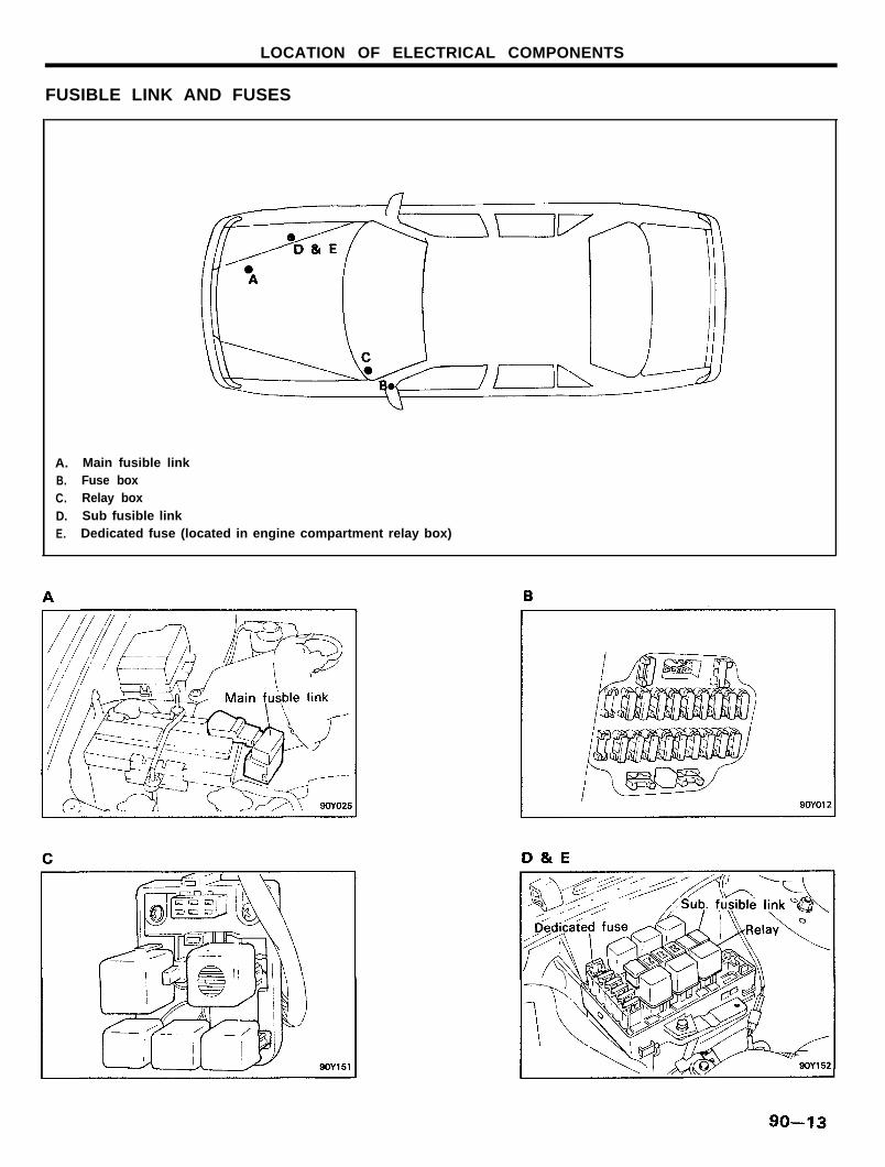
LOCATION OF ELECTRICAL COMPONENTS
FUSIBLE LINK AND FUSES
A. Main fusible linkB. Fuse boxC. Relay boxD. Sub fusible linkE. Dedicated fuse (located in engine compartment relay box)
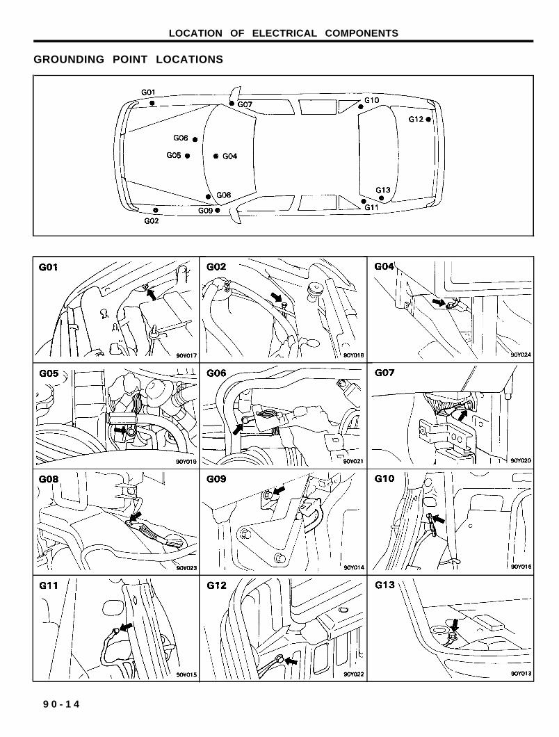
LOCATION OF ELECTRICAL COMPONENTS
GROUNDING POINT LOCATIONS
9 0 - 1 4

FUSIBLE LINKS AND FUSES
FUSIBLE LINK
SPECIFICATIONS
FUSIBLE LINKS AND FUSES
INSPECTION
1. Check for a blown fusible link with an ohmmeter.2. If a fusible link burns out, there is a short or some other
problem in the circuit. Carefully determine the cause andcorrect it before replacing the fusible link.
NOTEThe fusible link will blow within 15 seconds if a highercurrent than specified flows through the circuit.
FUSE BOX
INSPECTION
1. Be sure there is no play in the fuse holders, and that theholders hold the fuses securely.
2. Check the fuse capacities for each circuit.3. Check for any blown fuses.
If a fuse is to be replaced, be sure to use a new fuse of thespecified capacity. Always determine why the fuse has blown
and eliminate the problem before installing a new fuse.
CAUTIONNever use a fuse of higher capacity than specified.

IGNITION SWITCH
IGNITION SWITCHINSPECTION
1. Separate the connector located under the steering column.
2. Inspect the switch continuity between the terminals.3. If continuity is not as specified, replace the switch.
NOTEm indicates that there is continuity between the terminal.
RO : Round the locking barRE : Return the locking barL : Lock
F : Free
9 0 - 1 6

INSTRUMENTS, GAUGES AND WARNING LAMPS
INSTRUMENTS, GAUGES AND WARNING LAMPSINSTRUMENT CLUSTERSPECIFICATIONSAnalog Type
Items
Speedometer
TypeTachometer
TypeFuel gauge
PypeTemp gauge
TypeVolt gauge
TypeOil gauge
Type
Indicators and Warning Lamps
Items
Indicator lampsDirection indicator (LH. RH) WBattery charging WOil pressure WBrake failure WDoor warning WRear window defogger WCheck engine WLow beam WSafety belt WHigh beam WLow Beam WHazard WLow fuel WTrunk lid opener WLow washer WIlluminationA/T position indication
PRND2LOD OFF
Specifications
Eddy current, push connection type
Electronic type
Air cored type
Air cored type
Air cored type
Air cored type
Specifications
Wattage
1.21.21.21.21.21.21.21.21.21.21.21.23.01.21.23.4
1.21.21.21.21.21.21.2
Color
GreenRedRedRedAmberAmberAmberGreenRedBlueBlueRedAmberAmberAmber
AmberAmberGreenGreenGreenGreenAmber
9 0 - 1 7

INSTRUMENTS, GAUGES AND WARNING LAMPS
SERVICE STANDARD
Items
Speedometer indication error
Tachometer indication error
Fuel gauge
Specifications
Standard speed (MPH) 10 20 40 55 75 100
Allowable error (MPH) ±1.5 ±1.5 ±1.5 ±1.5 ±1.5 ±1.5
Standard speed (km/h) 20 40 60 80 1 0 0 1 2 0 1 4 0 160
Tolerace (km/h) +4 +3 +4 +5 +5 +5.5 +5.5 +5.50 0 0 0 0 +0.5 +0.5 +0.5
Standard RPM 1000 2 0 0 0 3 0 0 0 4000 5 0 0 0 6 0 0 0 7000
Allowable RPM ±100 ±125 ±150 ±150 ±150 ±180 ±210
Fuel tank level E 1 / 2 F
Standard resistance (0) 95 32.5 6.5
Indication error 2°24’ ±5 +2°24’
Fuel sender
Water temperature gauge
Water temperature sender
Float position
Resistance (0)
Allowable error (0)
Temperature (°C)
Angle
Tolerance
Temperature (°C)
Resistance (0)
F 1.2 E
3 32.5 110
±2 ±4 ±7
60 85 110 125
- 3 0 ° -7° -7° +30°
+ 2° + 2°- 3 ° - 3 °
±5
60 85 110 125
125 48.4 24 15.2
Voltmeter gauge Voltage (V) 8 10 12 14 16
Angle - 3 0 ° -16° 0° 16° 30°
Allowable error (V) ±0.5 ±0.5 ±0.6
9 0 - 1 8

INSTRUMENTS, GAUGES AND WARNING LAMPS
TIGHTENING TORQUE
9 0 - 1 9

TROUBLESHOOTING
Problem
Tachometer does not
operate
Fuel gauge does not
operate
Fuel level warninglamp does not light
Water temperaturegauge does not
operate
Low oil pressurewarning lamp does not
light
Brake warning lamp
does not light
Open door warning
lamp does not light
Seat belt warning
does not operate
Possible cause Remedy
NO.12 (1OA) fuse blown Replace fuse and check for shortTachometer faulty Check tachometerWiring faulty Repair as necessary
NO.12 (1OA) fuse blown Replace fuse and check for short
Fuel gauge faulty Check gaugeFuel sender faulty Check fuel senderWiring or ground faulty Repair as necessary
NO.12 (1OA) fuse blown Replace fuse and check for short
Bulb burned out Replace bulbFuel level sensor faulty Check switchWiring or ground faulty Repair as necessary
NO.12 (1OA) fuse blown Replace fuse and check for short
Water temperature gauge faulty Check gaugeWater temperature sender faulty Check senderWiring or ground faulty Repair as necessary
NO.12 (1OA) fuse blown Replace fuse and check for short
Bulb burned out Replace bulbOil pressure sender faulty Check sender
Wiring or ground faulty Repair as necessary
NO.12 (1OA) fuse blown Replace fuse and check for short
Bulb burned out Replace bulbBrake fluid level warning switch faulty Check switch
Parking brake switch faulty Check switchWiring or ground faulty Repair as necessary
NO.8 (1OA) fuse blown Replace fuse and check for short
Bulb burned out Replace bulb
Door switch faulty Check switchWiring or ground faulty Repair as necessary
NO.8 (1OA) fuse blown Replace fuse and check for short
Bulb burned out Replace bulb
Door warning switch faulty Check switch
Buckle switch faulty Check switch
E.T.A.C.S. faulty E.T.A.C.S.Wiring or ground faulty Repair as necessary
9 0 - 2 0

INSTRUMENTS, GAUGES AND WARNING LAMPS
SERVICE ADJUSTMENT PROCEDURES
SPEEDOMETER
Inspection
1. Using a speedometer tester, inspect the speedometer forallowable indicating error and check the operation of the
odometer.
NOTETire wear and tire over or under inflation will increase theindication error.
2. Check the speedometer for pointer vibration and abnormalnoises.
NOTEPointer vibration can be caused by a loose or dry
speedometer cable.
Standard indication (MPH) 10 20 40 55 75
Allowable error (MPH) ±1.5 ±1.5 ±1.5 ±1.5 ±1.5
SPEEDOMETER CABLE
Insert the cable until the stopper properly fits into the
speedometer groove.
CAUTIONPoor installation of the cable may cause a fluctuating pointer,
noise and a damaged harness inside the instrument panel.
TACHOMETER
Inspection
1. Connect a tachometer and start the engine.2. Compare the tester and tachometer indications.
If the difference is excessive, replace the tachometer.
CAUTION1) Reversing the connections of the tachometer will
damage the transistor and diodes.
2) When removing or installing the tachometer, becareful not to drop it or subject it to severe shock.
9 0 - 2 1

INSTRUMENTS, GAUGES AND WARNING LIGHTS
FUEL GAUGE AND FUEL SENDER
FUEL GAUGE SIMPLE TEST
1. Lift up the vehicle and disconnect the connector of the fuelgauge from the fuel sender.
2. Ground to the harness side connector via (terminals 3) the12V, 3.4W bulb.
3. Turn the ignition key to the ON position.
4. Check to be sure that the test bulb flashes and that theindicator moves.
Fuel Sender Resistance Check
1. Measure (with the float at the “F” position and at the “E”
position) the resistance between ground and the senderterminal for the fuel gauge.
Standard specification : Point F : 3±2 fi
Point E : 110±7 R
2. Also check that the resistance changes smoothly when thefloat is moved to “F” and “E”.
Fuel Level Sensor Check
1. Connect the sender with a test lamp (12V, 3,4W) to thebattery and immerse it in water.
2. The lamp should be off while the thermistor is beneath thewater, and should illuminate when the sender is taken outof the water.
NOTEIf there is a malfunction, replace the fuel sender as anassembly.
CAUTION
After completing this test, wipe the sender dry and installit in the fuel tank.
WATER TEMPERATURE GAUGE AND WATERTEMPERATURE SENDER
WATER TEMPERATURE GAUGE SIMPLE TEST
1. Disconnect the wiring connector from the water temperature
sender in the engine compartment.
2. Ground to the harness side connector via the 12V, 3.4Wbulb.
3. Turn the ignition key to the ON position.4. Check to be sure that the test bulb flashes and that the
indicator moves.
9 0 - 2 2

INSTRUMENTS, GAUGES AND WARNING LIGHTS
WATER TEMPERATURE SENDER
1. Using an ohmmeter, measure the resistance between theterminal and ground.
2. If the resistance value is not as shown in the table below,replace the temperature sender.
Temperature °C (°F) 60 (140) 110 (230)
Resistance 0 125 24
OIL PRESSURE SWITCH AND OIL PRESSURE
SENDER
OIL PRESSURE SENDER
1. Check the engine oil level. Add oil if insufficient, or replaceit if the connection is bad.
2. Measure the resistance changes by connecting an ohmmeterbetween a good ground (vehicle body) and the terminal of
the sender.
3. Refer to service standard.
OIL PRESSURE SWITCH
Specifications
Type contact points
Lighting oil pressure 0.3 kg/cm2 (4.27 psi)
If operation is not as specified, replace the oil pressure switch.
VOLTAGE GAUGE
INSPECTION
1. Connect the voltmeter in parallel with the volt gauge.
2. The voltmeter indication should be equal to the volt gauge.
Indication Tolerance
Standard
10V12V16V
Tolerance
+ 0.5V+ 0.5V+ 0.6V
9 0 - 2 3

INSTRUMENTS, GAUGES AND WARNING LAMPS
BRAKE WARNING LAMP AND SWITCH
The brake fluid level sensor or the parking brake switch isswitched ON, and the brake warning lamp illuminates, when,
with the ignition switch at the “ON” position, the brake fluid levelis at or below the specified level, or the parking brake lever is
pulled.
NOTEThe brake fluid level sensor is built into the master cylinder
reservoir cap.
Parking Brake Switch
The parking brake switch is a push type and located under theparking brake lever. To adjust, move the switch mount up anddown with the parking brake lever released all the way.
DOOR SWITCH
INSPECTION
Remove the door switch and check for continuity between theterminals.
If continuity is not as specified, replace the door switch
9 0 - 2 4

INSTRUMENTS, GAUGES AND WARNING LAMPS
COMPONENTS
ANALOG TYPE
9 0 - 2 5

INSTRUMENTS, GAUGES AND WARNING LIGHTS
PRINTED CIRCUIT BOARD
CIRCUIT DIAGRAM
9 0 - 2 6

MULTIFUNCTION SWITCH
MULTIFUNCTION SWITCHR E M O V A L
1. Remove the steering wheel.2. Remove the steering column shroud.3. Remove the multifunction switch mounting screws.
4. Disconnect the multifunction switch wiring terminal.
CAUTIONMake sure the wire leads are not being pulled when youmove the lever.Check that lever works freely without binding.
Switch Attaching Plane

MULTIFUNCTION SWITCH
INSPECTION
Operate the switch and check the continuity between theterminals.
LIGHTING SWITCH
DIMMER/PASSING SWITCH
TURN SIGNAL SWITCH
WIPER SWITCH
WASHER SWITCH
9 0 - 2 8

MULTIFUNCTION SWITCH
AUTOMATIC SPEED CONTROL SWITCH (CRUISE)
NOTEo LIGHTING SW
I = TAILII = LIGHTING
o DIMMER/PASSING SWHU = HEAD LAMP UPPER BEAMHL = HEAD LAMP LOWER BEAM
P = PASSING
9 0 - 2 9

LIGHTING SYSTEM
ItemSpecification
U.S.A. & CANADA EXCEPT U.S.A. & CANADA
Front combination lamp
Headlamp 65/45 W 60/55 W
Turn signal lamp 28/8 W -
Position lamp - 4 W
Front side marker and reflex reflector lamp 5 W -
Front turn signal lamp - 21 w
Side repeater lamp - 4 W
Rear combination lamp (outside)Turn signal lamp 27 W 21 W
Tail and stop lamp 27/8 W 21/5 W
Side marker and reflex reflector lamp 5W -
Rear combination lamp (inside)Tail and stop lamp 27/8 W 21/5 W (Except EC)
Back up lamp 27 W 21 W
Rear for lamp (EC only) - 21 W
Interior lamp
Luggage and glove box lamp 5 W
Room lamp 10 W
Map lamp 8 W
Door lamp 5 W
High mounted stop lamp 17 W -
License plate lamp 8W 5 W
Flasher unit
Turn signal blinking frequency 85 ± 10 C/M at 12.8 V
Hazard warning blinking frequency 80 ± 12 C/M at 12.8 V
9 0 - 3 0

TROUBLESHOOTING
Problem
Only one lamp does not light(all exterior)
Headlamps do not light
Tail, parking and licenselamp do not light
Stop lamps do not light
Stop lamps stay on
Instrument lamps do not
light (taillamps light)
Turn signal does not flash
on one side
Turn signal does not operate
Hazard warning lamp does
not operate
Possible cause Remedy
Bulb burned out Replace bulb
Socket, wire or ground faulty Repair as necessary
Bulb burned out Replace bulb
Fusible link blown Replace fusible link
Headlamp relay faulty Check relay
Lighting switch faulty Check switch
Wiring or ground faulty Repair as necessary
Taillamp fuse blown Replace fuse and check for short
Fusible link blown Replace fusible link
Taillamp relay faulty Check relayLighting switch faulty Check switch
Wiring or ground faulty Repair as necessary
Circuit fuse blown Replace fuse and check for short
Stop lamp switch faulty Adjust or replace switch
Wiring or ground faulty Repair as necessaryBulb burned out Replace bulb
Stop lamp switch faulty Adjust or replace switch
Lamp control rheostat faulty Check rheostat
Wiring or ground faulty Repair as necessary
Bulb burned out Replace bulb
Turn signal switch faulty Check switch
Wiring or ground faulty Repair as necessary
Turn signal fuse blown Replace fuse and check for short
Turn signal flasher faulty Check flasher
Turn signal switch faulty Check switchWiring or ground faulty Repair as necessary
Hazard fuse blown Replace fuse and check for short
Turn signal flasher faulty Check flasher
Hazard switch faulty Check switch
Wiring or ground faulty Repair as necessary
9 0 - 3 1

HEADLAMP AIMING (FOR U.S.A. CANADA)
PRE-AIMING INSTRUCTIONS
1. Test dimmer switch operation.2. Observe operation of high beam indicator lamp mounted in
the instrument cluster.
3. Inspect for badly rusted of faulty headlamp assemblies.These conditions should be corrected before a satisfactory
adjustment can be made.4. Place the vehicle on a level floor.
5. Bounce the front suspension through three (3) oscillationsby applying body weight to the bumper.
6. Check and correct tire inflation pressures.7. Rock vehicle sideways to allow vehicle to assume its normal
position.8. If the fuel tank is not full, place a weight in the trunk of the
vehicle to simulate the weight of a full tank.
9. There should be no other load in the vehicle other than thatof the driver or substituted weight of approximately 70 kg(150 Ibs.) placed in the driver’s position.
10. Thoroughly clean the headlamp lenses.
COMPENSATING THE AIMERS FORFLOOR SLOPE
The floor level offset dial must coincide with the floor slope for
accurate aiming. Calibration fixtures are included with the
aimers
1. Attach one calibration fixture to each aimer. Fixtures will
easily snap into position on the aimer when properly
positioned.2. Place the aimers at the center line of each wheel on one
side of the vehicle. Unit A must be placed at the rear wheelwith the target facing forward. Unit B must be placed at the
front wheel with the target facing rearward.
3. Adjust the thumb screw on each calibration fixture byturning either clockwise or counter-clockwise until the levelvial bubble registers in a centered, level position.
4. Look into the top port hole of Unit A. Turn the horizontal knob
until the split image is aligned.
5. Transfer the plus or minus reading indicated on thehorizontal dial to the floor level offset dial on each aimer.Press the floor level dial inward to set reading.
6. Remove the calibration fixtures from both units.
9 0 - 3 2

LIGHTING SYSTEM
TESTING AIMER CALIBRATION
The aimer calibration may be off due to extended use.
Calibration fixtures used in conjuction with the aimers can beused to check and adjust the aimer.
Turn the thumb adjusting screw on each calibration fixture
until it is approximately the same distance as the supporting
posts.
1.
2.
3.
4.5.
Attach the calibration fixtures to each unit with the level
vials on top.Locate a true vertical plate glass window or smooth surfaceand position the aimers three to five feet apart so that thesplit image targets can be located in the viewing ports.Set the floor level dial to zero.
6.
Rotate the thumb adjusting screws on each calibrationfixture until the level vials on the fixtures are centered.With both calibration level vials centered, turn the vertical
dial knobs on each aimer until the aimer level vials arecentered. If the aimer vertical dial pointers read between 1/2up and 1/2 down, the aimers are within allowable vertical
tolerance, Recalibrate the units if they are beyond these
limits.
Vertical dial pointer reading (on each aimer) . . . . . . . . . . . .1/2 up to 1/2 down
7. Adjust the horizontal dial knob on each aimer until the split
image targets align. If the aimer horizontal dial pointers read
between 1 left and 1 right, the aimers are within allowable
tolerance limits. Recalibrate the units if beyond these limits.
Horizontal dial pointer reading (on each aimer) . . . . . . . . . .1 left to 1 right
MOUNTING AIMERS
1. Remove the calibration fixture from the each unit.2. As shown in the figure, install the articulating vacuum cup
assembly (A), vacuum extension plate (B) and small universaladaptor (C) to each unit.

3. Mark the length of the adjustable rod as shown in the figure.
4. Position the aimers on the headlamps pushing the pistonhandle forward, engaging the rubber suction cup. lmme-
diately pull back the piston handle until it is locked in place.
NOTESteel inserts are molded into position on the adaptor to
insure accuracy. These inserts should be in contact withthe three guide points on the lamps when the aimers are
properly positioned.
HORIZONTAL ADJUSTMENT
1. Set the horizontal dial to zero.
2. Check to see that the split image target lines are visible inthe viewing port. If necessary, rotate each aimer slightly to
locate the target.3. Turn the horizontal screw on the side of the headlamp until
the split image of target line appears in the mirrors as onesolid line. To remove “backlash”, make the final adjustmentby turning adjusting screw in a clockwise direction.
4. Repeat the last three steps on the apposite headlamp.
VERTICAL ADJUSTMENT
1. The vertical dial should be set at zero. (For passengervehicles, “O” setting is generally required. For special
settings, consult local state laws.)
2. Turn the vertical adjusting screw until the level bubble iscentered between the lines.
3. Repeat the last two steps on the opposite headlamp.4. Re-check the target alignment on both aimers and readjust
the horizontal aimer if necessary.
5. Remove the aimers by pressing “vacuum release” buttonlocated on the piston handle.
9 0- 3 4

LIGHTING SYSTEM
AIMING WITH SCREEN
HEADLAMP AIMING PREPARATION
Place the vehicle on a level floor 7.6 m (25 feet) apart from theaiming screen or a light-colored wall. Four lines of adhesive tapeare required on the screen or wall:
1. Position a vertical piece of tape so that it is aligned with the
vehicle center line2. Position a horizontal piece of tape with reference to the
center line of the headlamp.
3. Position a vertical piece of tape on the screen for verticaladjustment, adjust the side screw for horizontal adjustment.
VISUAL HEADLAMP ADJUSTMENT
1. A properly aimed low beam will appear on the aiming screen
7.6 m (25 feet) in front of the vehicle. The shaded area as
shown in the illustration indicates a high intensity zone2. Adjust the low beam headlamps to match the low beam
pattern of the right and left headlamps.
NOTE
If the visual headlamp adjustment at low beam is made,
the adjustment at high beam is not necessary.
9 0 - 3 5

HEADLAMP AIMING (Except U.S.A. &Canada)
PRE-AIMING INSTRUCTIONS
The headlamps should be aimed with the proper beam-settingequipment and aimed in accordance with the equipment
manufacturers instructs.
NOTE
If there are any regulations pertinent to the aiming of
headlamps in the area where the vehicle is to be used,adjust
so as to satisfy those requirements.
Alternately turn the adjusting bolts to adjust the headlamp
aiming. If beam-setting equipment is not available, proceed as
follows:1. Inflate the tires to the specified pressure and remove the
load from the vehicle except a driver, spare tire and tools.2. The vehicle should be placed on the level floor.
3. Draw vertical lines (vertical lines passing through respective
headlamp centers) and a horizontal line (horizontal linepassing through center of headlamps) on the screen.
4. With the headlamp and battery in normal condition, aim theheadlamps.
Make the vertical and horizontal adjustment of the lower
beam to the standard values by using the adjusting knobs.
9 0 - 3 6
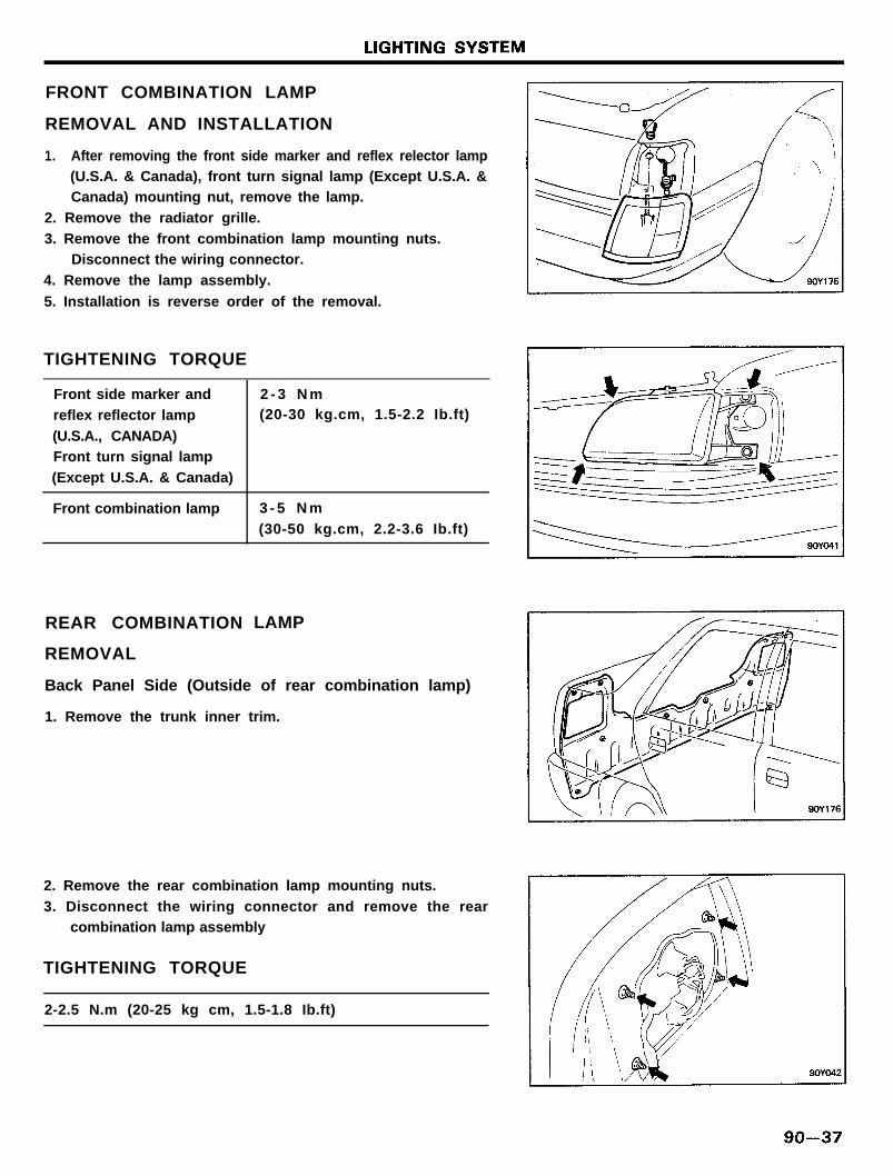
FRONT COMBINATION LAMP
REMOVAL AND INSTALLATION
1. After removing the front side marker and reflex relector lamp(U.S.A. & Canada), front turn signal lamp (Except U.S.A. &Canada) mounting nut, remove the lamp.
2. Remove the radiator grille.
3. Remove the front combination lamp mounting nuts.Disconnect the wiring connector.
4. Remove the lamp assembly.
5. Installation is reverse order of the removal.
TIGHTENING TORQUE
Front side marker and
reflex reflector lamp
(U.S.A., CANADA)Front turn signal lamp
(Except U.S.A. & Canada)
Front combination lamp
2 - 3 N m(20-30 kg.cm, 1.5-2.2 Ib.ft)
3 - 5 N m
(30-50 kg.cm, 2.2-3.6 Ib.ft)
REAR COMBINATION
REMOVAL
LAMP
Back Panel Side (Outside of rear combination lamp)
1. Remove the trunk inner trim.
2. Remove the rear combination lamp mounting nuts.
3. Disconnect the wiring connector and remove the rearcombination lamp assembly
TIGHTENING TORQUE
2-2.5 N.m (20-25 kg cm, 1.5-1.8 Ib.ft)

LIGHTING SYSTEM
Inside of trunk (Inside of rear combination lamp)
1. Disconnect the wiring connector.
2. Remove the rear combination lamp mounting nuts.3. Remove the rear combination lamp assembly.
TIGHTENING TORQUE
2-2.5 Nm (20-25 kg cm, 1.5-1.8 Ib.ft)
9 0 - 3 8

LIGHTING SYSTEM
HIGH MOUNTED STOP LAMP
COMPONENTS
9 0 - 3 9

LIGHTING SYSTEM
1. Remove the headlamp relay and taillamp relay.2. Check for continuity between the terminals.
HEADLAMP RELAY
NOTE
1. M indicates that there is continuity between theterminals.
2.01 m 10 indicates power supply connection.
TURN SIGNAL FLASHER UNIT
1. Connect the positive (+) lead from the battery to terminal Band the negative (-) lead to terminal E.
2. Connect the two turn signal lamps parallel to each other toterminal L and E, check that the bulbs turn on and off.
NOTEThe turn signal lamps should flash 60 to 120 times per
minute.If one of the front or rear turn signal lamps has an open
circuit, the number of flashes will be more than 120 perminute.
If the operation is not as specified, replace the flasher unit.
9 0 - 4 0

LIGHTING SYSTEM
HAZARD SWITCH
1. Remove the hazard switch located in the cluster housing.2. Operate the switch and check continuity between the
terminals by using an ohmmeter.
9 0 - 4 1

LIGHTING SYSTEM
DAYTIME RUNNING LIGHT (For CANADA)
SPECIFICATIONS
TIMING CHART
9 0 - 4 2

AUDIOSPECIFICATIONS
AM/FM RADIO WITH CASSETTE
BASE GRADE
Items
RadioReceiving bandTuning typeMemory (AM/FM)Frequency range
Amplifier
Output powerVolume type
Tape playerDeck type
Reproducing type
MEDIUM GRADE
Items
RadioReceiving bandTurning typeMemory (AM/FM)Frequency range
Amplifier
Output powerVolume type
Tape playerDeck typeEject typeReproducing type
C - 4 2 0
AM/FM1/FM2
E.T.R.
6 / 1 2AM : 530 - 1620 KHzFM : 87.5 - 108 MHz
MAX. 6W x 4CH
Rotary
Mechanical
Auto reverse
H 4 5 0
AM/FM1 /FM2
E.T.R.6 / 1 2AM : 530 - 1610 KHz
FM : 87.9 - 108 MHz
MAX. 25W x 2CHRotary
Full logicKey off releaseAuto reverse
H - 5 1 0 I HC-700
AM/FM1/FM2
E.T.R.6 /12AM : 530 - 1620 KHz
FM : 87.5 - 108 MHz
MAX. 20W x 2CH
Rotary
Mechanical
Auto reverse
AM/FME.T.R.6 / 6AM : 530 - 1620 KHzFM : 87.5 - 108 MHz
MAX. 25W x 2CH
Rotary
Mechanical
Auto reverse
AM/FM1 /FM2
E.T.R.6 /12AM : 530-1710 KHz
FM : 87.9- 108 MHz
MAX. 25W x 4CH
Rotary
Full logicKey off release
Auto reverse
H - 5 6 0 HC-800
AM/FM1 /FM2
E.T.R.6 / 1 2AM : 530-1620 KHz
FM : 87.9-108 Mhz
MAX. 25W x 2CH
Rotary
Full logicKey off release
Auto reverse
9 0 - 4 3

AUDIO
DELUXE GRADE
Items
RadioReceiving bandTurning type
Memory (AM/FM)
Frequency range
Tape playerDeck type
Eject type
Reproducing typeAmplifier
Output power
input impedanceSound dimensional arrayCompact disc player
Frequency responseSignal to noise ratio
PREMIUM GRADE
Items
Radio
Receiving band
Tuning typeMemory (AM/FM)Frequency range
Tape playerDeck type
Eject type
Reproducing typeAmplifier
Output powerInput impedance
Sound dimentional array
Compact disc player
Frequency responseCurrent
H - 6 0 0
AM/FM1 /FM2E.T.R.
6 /12
AM : 530 - 1620 KHzFM : 87.9 - 107.9 MHZ
Full logic
Key-off ejectAuto reverse
MAX. 25W x 4CH
MON. 10 Kn (8-12fl)S.D.A.-H3
H - 7 0 0
AM/FM1 /FM2E.T.R.
6 / 1 2AM : 530 -1620 KHz
FM : 87.9 - 107.9 MHz
Full logicKey-off eject
Auto reverse
MAX. 60W x 4CHN O M . 1 0 Kfl (8-12R)
S.D.A.-H4
5Hz-20KHz ± 1.0dB
NOM. 0.8A
H - 5 6 5
AM : 530 - 1710 KHz
FM : 87.9 - 107.9 MHz
Key-off release
5 HZ-20 KHz ± 1.0 dB
NOM. 85 dB (with lHF-A)
H - 5 9 0
AM : 530 - 1710 KHz
FM : 879 - 107.9 MHz
Key-off release
MAX. 40W x 4CH
9 0 - 4 4

SPEAKER
BASE AND MEDIUM GRADE
Items
Front speaker
Input powerRated impedance
DistortionSize
Rear speakerWoofer
Input powerRated impedance
Distortion
SizeTweeter
Input powerRated impedance
DistortionSize
Specifications
NOM. 20W (MAX. 40W)4 ± 0.6 iI (at 400 Hz, 1V)
MAX. 5% (at 400 Hz, 20W)
10 cm (4 in.)
NOM. 20W (MAX. 40W)4 ± 0.6 n (at 400 Hz, 1V)
MAX. 5% (at 400 Hz, 20W)
16 cm (6.5 in.)
NOM. 5W (MAX. 7W)4 ± 0.6 R (at 3 KHz, 1V)5% MAX. (at 100 KHz, 5W)
5 cm (2 in.)
DELUXE GRADE
Items
Front speakerMid-woofer
Input powerRated impedance
Distortion
SizeTweeter
Input powerRated impedanceDistortion
Size
Rear speakerWoofer (double)
Input powerRated impedanceDistortionSize
Specifications
NOM. 10W RMS (MAX. 20W RMS)4.0 ± 0.5 Q (at 400 Hz, 1V)
MAX. 5% (at 400 Hz, 2V)
10 cm (4 in.)
NOM. 10W RMS (MAX. 20W RMS)4.0 ± 0.5 fi (at 1 KHz, 1V)
MAX. 2.5% (at 4.3 KHz, 2V)5 cm (2 in.)
NOM. 15W RMS (MAX. 30W RMS)
3.0 ± 0.5 n (at 400 Hz, 1V)MAX. 1.5% (at 400 Hz, 2V)
16 cm (6.5 in.)
9 0 - 4 5

AUDIO
PREMIUM GRADE
Items
Front speakerMid-woofer
Input powerRated impedance
Distortion
SizeTweeter
Input power
Rated impedanceDistortion
Size
Rear speaker
Woofer (coaxial)
Input powerRated impedance
Distortion
Size
Door speaker, sub woofer speaker
Woofer (single)
Input powerRated impedanceDistortion
Size
Specifications
NOM. 10W RMS (MAX. 20W RMS)
4.0 ± 0.5 Q (at 400 Hz, 1V)
MAX. 5% (at 400 Hz, 2V)10 cm (4 in.)
NOM. 10W RMS (MAX. 20W RMS)4.0 ± 0.5 il (at 1 KHz, 1V)
MAX. 2.5% (at 4.3 KHz, 2V)
5 cm (2 in.)
NOM. 15W RMS (MAX. 30W RMS)
3.0 ± 0.5 Cl (at 400 Hz, 1V)
MAX. 3% (at 400 Hz, 2V)
16 cm (6.5 in.)
NOM. 15W RMS (MAX. 30W RMS)
3.0 ± 0.5 fl (at 400 Hz, 1V)MAX. 1.5% (at 400 Hz, 2V)
16 cm (6.5 in.)
ANTENNA
Items
Manual antenna
TypeInsulating resistance
Electrostatic capacity
Operating forcePower antenna
Rated voltage
Operating amperageInsulating resistance
Electrostatic capacity
Operating force
Specifications
Telescopic rod
MIN. 100 Ma (at DC 500V megger)
80 ± 8 PF
0.3 ~ 6 kg
DC 12VMAX. 6A (Lock current MAX 15A)
MIN. 100 Ma (at DC 500V megger)
80 ± 8 PF
5 kg
9 0 - 4 6

AUDIO
TROUBLESHOOTING
There are 5 areas where a problem can occur the wiringharness, the radio, cassette tape deck, the speaker, and theantenna.
Your job in troubleshooting is to isolate the problem to a
particular area.
9 0 - 4 7

AUDIO
CHART 1
9 0 - 4 8

AUDIO
CHART 2
9 0 - 4 9

AUDIO
CHART 3
9 0 - 5 0

AUDIO
CHART 4
1. RADIO
9 0 - 5 1

AUDIO
2. TAPE
CHART 5
9 0 - 5 2

AUDIO
CHART 6
CHART 7
9 0 - 5 3

AUDIO
CHART 8
9 0 - 5 4

AUDIO
COMPACT DISC PLAYER
TROUBLESHOOTING
Symptoms
o Skipso Stuck on one tracko Disc ejects during play
o Disc loads but ejects after
a few seconds
o Disc loads but functionswitch won’t operate anddisplay is erratic.
o Error indication
Cause
o Scratches
o Fingerprint marks or dust (Unclean
surfaces)
o Pin holes
o Disc is not centered on clampingmechanism.
o Rough edges
o Battery voltage drop or a momentary
loss of B+.
o Laser diode protection circuit isbeing activated due to excessivescratches or environmental heat.
Solution
o Handle disc by edge only.o Keep disc clean by using a cleaning kit
specifically designed for compactdiscs.
o Check for pin holes by holding disc upto a light aspect and observing it.
o Defective disc should not be used in
player.
o Disc center hole can be defective
during manufacturing process.
o Defective disc should not be used in
player.
o Rough edges may touch mechanismparts and can be corrected by lightly
sanding disc edges.
o When replacing or charging vehicle
battery, reset button should bedepressed to restore normal function.
o An excessive scratched disc maycause the tracking servo to move morethan necessary, resulting in internal
heat build up.o Remove disc and allow C.D. player to
return to a safe operating temperature
before re-inserting.
9 0 - 5 5

AUDIO
SERVICE ADJUSTMENT PROCEDURES
FUSE REPLACEMENT
Be sure to use the specified fuse when making a replacement.
Radio unit Permissible current
LOW GRADE 1A & 3A
MEDIUM GRADE 3A & 5AI
DELUXE GRADE 3A & 5A
PREMIUM GRADE 3A & 5A
CAUTIONSubstituting with a higher capacity fuse. or connection
without a fuse may result in damage to the unit.
TAPE HEAD AND CAPSTAN CLEANING
1. To obtain optimum performance, clean the head and capstan
as often as necessary, depending upon frequency of use andtape cleanliness.
2. To clean the tape head and capstan, use a cotton swabdipped in ordinary rubbing alcohol.
Wipe the head and capstan.
SPEAKER CHECKING
1. Check the speaker by using an ohmmeter.
If an ohmmeter indicates the impedance of the speaker whenchecking between the speaker (+) and speaker (-) of the
same channel, the speaker is ok.
2. If clicking sound is emitted from the speaker when theohmmeter plugs touch the speaker terminals, the speaker is
ok.
ANTENNA (AUTOMATIC)
INSPECTION
Connect the motor terminals directly to the battery and checkthat the motor operates smoothly. Next, reverse the polarity and
check that the motor operates smoothly in the reverse direction.
9 0 - 5 6

AUDIO
STRUCTURAL VIEW
- F R O N T S I D E -
- B A C K S I D E -
Ground terminal
13P Connector (M34-1)
9 0 - 5 7

AUDIO
STRUCTURAL VIEW (BASE GRADE)
- F R O N T S I D E -
- B A C K S I D E -
9 0 - 5 8

AUDIO
STRUCTURAL VIEW (MEDIUM GRADE)
- F R O N T S I D E -
H 4 5 0 H - 5 6 0
- B A C K S I D E -
13P Connector (M34-1) 14P Connector (M34-3)
9 0 - 5 9

AUDIO
STRUCTURAL VIEW (DELUXE GRADE)
- F R O N T S I D E -
- B A C K S I D E -
13P Connector (M34-1) 14P Connector (M34-3)
9 0 - 6 0

AUDIO
STRUCTURAL VIEW (PREMIUM GRADE)
H - 7 0 0
- F R O N T S I D E -
H - 5 9 0
-BACK SIDE-
5P Connector (M34-2)
9 0 - 6 1

REMOVAL AND INSTALLATION
RADIO UNIT
1. Remove the center lower crash pad facia panel.
2. Unscrew the mounting screws and remove the radio unitfrom the mounting bracket.
3. Replace in reverse order of preceding steps.
SPEAKER
FRONT SPEAKER
1. Remove the front speaker grille.2. Remove the speaker mounting bolts.
3. Remove the speaker assembly.4. Replace in reverse order of the preceding steps.
REAR SPEAKER
1. Remove the speaker mounting nuts.2. Disconnect the wiring connector.
3. Replace in reverse order of the preceding steps.
9 0 - 6 2

AUDIO
ANTENNA (AUTOMATIC)
REMOVAL
1. Remove the luggage side trim.
2. Remove the antenna mounting nuts and tapping screw forground.
3. Disconnect the wiring connector and antenna cable.
4. Remove the antenna assembly.
5. Replace in reverse order of the preceding steps.
9 0 - 6 3

WINDSHIELD WIPER AND WASHER
WINDSHIELD WIPER AND WASHERSPECIFICATIONS
Items
Wiper motorRated voltage
Testing voltageStarting voltage
Operating voltage rangeLoad speed (10 kg.cm)
LowHigh
Load speed (40 kg.cm)LowHigh
Wiper bladeWiping angle
Driver’s side
Passenger’s side
Wiper blade length
Intermittent wiper relay
Rated voltage
Operating voltage rangeLoad capacity range
Windshield washer
Motor typePump typeRated voltage
CurrentDischarge pressureFlow rate
Over load capacity (continuous operation)With water
Racing
Specifications
DC 12V13.5 V (terminal voltage)
MAX. 8VDC 10 ~ 15 V
48 ~ 56 rpm/MAX. 3.5 A
64 ~ 78 rpm/MAX. 4.5 A
40 ~ 48 rpm/MAX. 5.5 A
56 ~ 68 rpm/MAX. 7 A
DC 12 V
DC 9 ~ 16 V
MAX. 60 A
DC ferrite magnet typeCentrifugal pump
DC 12 VMAX. 3.9 A
1.2 kg/cm2
Min. 1320 cc/min.
MAX. 60 secMAX. 20 sec
9 0 - 6 4

COMPONENTS
WINDSHIELD WIPER AND WASHER
9 0 - 6 5

WINDSHIELD WIPER AND WASHER
TROUBLESHOOTING
Problem
Wipers do not operate orreturn to off position
Wipers do not operate in INT
position
Washers do not operate
Possible cause
Wiper fuse blown
Wiper motor faultyWiper switch faulty
Wiring or ground faulty
Intermittent relay faultyWiper switch faulty
Wiper motor faultyWiring or ground faulty
Washer hose or nozzle clogged
Washer motor faultyWasher switch faulty
Wiring faulty
SERVICE ADJUSTMENT PROCEDURES
WIPER MOTOR
Speed operation check
1. Remove the connector from the wiper motor.
2. Attach the positive (+) lead from the battery to terminal 5and the negative (-) lead to terminal 3.
3. Check that the motor operates at low speed.
4. Connect the positive (+) lead from the battery to terminal 6and the negative (-) lead to terminal 3.
5. Check that the motor operates at high speed.
Remedy
Replace fuse and check for short
Check motorCheck switch
Repair as necessary
Check intermittent relay.
Check switchCheck motor
Repair as necessary
Repair as necessary
Replace motorCheck switchRepair as necessary
Automatic stop operation check
1. Operate the motor at low speed.
2. Stop the motor operation anywhere except at the off positionby disconnecting terminal 5.
3. Connect terminals 5 and 2.
4. Attach the positive (+) lead from the battery to terminal 1.5. Check that the motor stops running at the off position.
9 0 - 6 6

SERVICE POINTS OF REMOVAL
REMOVAL OF FRONT DECK PANEL
Unscrew the mounting screws to pry up the front deck panel and
remove the front deck panel.
REMOVAL OF AIR INLET GARNISH
Remove the air inlet garnish while pressing the tab.
REMOVAL OF WIPER MOTOR
Loosen the wiper motor assembly mounting bolts, and thenremove the wiper motor assembly.Disconnect the linkage and the motor assembly, and then
remove the linkage.
CAUTIONBecause the installation angle of the crank arm and the motor
has been set, do not remove them unless it is necessary todo so. If they must be removed, remove them only aftermarking their mounting positions.
SERVICE POINTS OF INSTALLATION
INSTALLATION OF WIPER ARM
Mount the wiper arms onto the pivot shaft so that the stopping
position of the wiper blades is in agreement with the standard
specifications.
Standard specifications (distance between the blade tip andthe front deck garnish) : 30 ± 3 mm (1.2 in.)

WINDSHIELD WIPER AND WASHER
WINDSHIELD WASHER
COMPONENTS
INSPECTION
WASHER MOTOR
1. With the washer motor installed to the washer tank, fill thewasher tank with water.
2. Connect battery positive (+) and negative (-) cables toterminals 2 and 1 respectively to see that the washer motorruns and water is pumped.
SERVICE ADJUSTMENT PROCEDURES
1. Check the washer fluid contact point.
2. Adjust the washer fluid contact point by using a metal wireto move the washer nozzle ball.
3. If the amount of washer fluid ejected is too small, check forclogged, bent or crushed washer piping. Check the clippedpoints too, because the tube might be crused.
9 0 - 6 8

WINDSHIELD WIPER AND WASHER
WINDSHIELD WIPER AND WASHER SWITCH
INSPECTION
Inspect the switch continuity between the terminals.
If continuity is not as specified, replace the switch.
INTERMITTENT WIPER RELAY
CIRCUIT DIAGRAMFIG 1
9 0 - 6 9

WINDSHIELD WIPER AND WASHER
INSPECTION
The intermittent relay operating time is controlled by variableresistance.
When the wiper system has been troubleshooted, replace the
intermittent relay with other new one. And then the system iscompletely operated, the relay is faulty.
WIPER BLADE RUBBER REPLACEMENT
1. Pull out the rubber and backing blade from the stopper side.
2. Remove the backing blade from the rubber.3. To attach a new rubber, assemble the rubber and backing
blade, insert from the direction opposite the stopper, and
secure by the stopper. Note that, because the backing bladeis curved, installation should be as shown in the figure.
9 0 - 7 0

CLOCKSPECIFICATIONS
Items Specifications
Rated voltage
Operating voltage range
Time accuracyOperating temperature range
Current consumption (with DC 13V)
DC 12VDC 10 ~ 16VWithin ~ 2 sec./day (at DC 13V)
- 3 0 ~ +80°C (-22 ~ +176°F)
MAX. 150 mA
REMOVAL
1. Remove the 4 screws and pull out the cluster.
2. Disconnect the wiring connector.3. Remove the digital clock assembly by unscrewing the 2
screws.
CAUTION
The clock is composed of delicate electronic componentscontaining a crytal oscillator, transistor, etc. and should behandled with care. Specialized technical skill is needed torepair the internal mechanism of this clock. Do not
attempt to disassemble it. If the clock itself is mal-functioning, replace the entire assembly.
9 0 - 7 1

CIGARETTE LIGHTERSPECIFICATIONS
Items Specification
Max. input 120W
Insulation resistance MIN. 5Mfi (at the 500V megger)
Return time 13 ± 5 sec. (after pushing the lighter in)
Break temperature of fuse °C (°F) 138 ~ 151°C (278.4 ~ 303.4°F)
INSPECTION
1. Take out the plug.2. Examine the element spot connection for remnants of
tobacco and other meterials.3. Using an ohmmeter, check for the continuity of the element.
Cautions for use of the cigarette lighter socket asanxiliary power
1. When using a “plug-in” type of accessory, do not useanything with a load of more than 120W.
2. It is recommended that only the lighter be inserted into theholder.
9 0 - 7 2

SLIDING SUN ROOF
SLIDING SUN ROOFSPECIFICATIONS
Items
Sun roof motor
Rated voltage
Operating voltage
Testing voltage
No load rotation and electric current
Restriction torque and electric current
Clutch quality for output shaft
Early days torque
20,000 cycle test
Insulating resistance
Sun roof relay
Rated voltage
Rated load
Operating voltage
Operating temperature
Excitation current
Voltage drop (between both terminals)
Sun roof motor switch
Rated load
Type of operation
Operating force
Specifications
DC 12V
D C 9 ~ 1 5 V
DC 13 ± 0.2 V
MAX 180 rpm, MAX. 6 A
MIN 50 kg.cm, MAX 35 A
30 ~ 40 kg.cm
25 ~ 50 kg.cm
MIN 1Mfl (with 200 V megger)
DC 12 V
Motor 6 A
Lock 15 A
DC 9 - 15 V
- 4 0 - 100°C (40 ~ 212°F)
MAX. 250 mA
MAX. 0.15 V
DC 12 V, 1 A
Push ON and self return
0.5 ~ 1.0 kg
9 0 - 7 3

SLIDING SUN ROOF
INSPECTION
MOTOR
1. Disconnect the motor connector.2. Apply DC 12V to the 0.85 YR wire and ground the 0.85Y
wire.
3. Check that the motor turns in the direction to tilt up and
closed position.4. Reverse the connections and check that the motor turns from
open, to closed, to tilt up position.
RELAY
1. Check the continuity between the terminals “A“ and “B”, “C”
and “F” by using an ohmmeter.2. Apply DC 12 to the terminal “A”.3. Ground the terminal “B”.
4. Check for continuity between the terminals “C” and “E”.
SWITCH
Use an ohmmeter to check the continuity of the switch.If the continuity is not as specified, replace the switch.
9 0 - 7 4

PASSIVE SEAT BELT
PASSIVE SEAT BELT (FOR U.S.A.)SPECIFICATIONS
Items
Electronic control unit
Rated voltage
Operating voltage
Testing voltage
Operating temperature
Motor
Rated voltage
Operating voltage
Operating temperature
SPECIAL SERVICE TOOL
Specifications
DC 12 V
D C 9 - 1 6 V
DC 13.5 ~ 14.5 V
- 4 0 ~ +85°C (-40 ~ +185°F)
DC 12 V
D C 9 - 1 6 V
- 35 ~ +85°C (-31 ~ +185°F)
Tool(Number and name)
Illustration Use
09888 - 33000Diagnostic controller
Reading diagnosis
9 0 - 7 5

PASSIVE SEAT BELT
COMPONENTS
Passive seat belt rail cover
Track mounting clip-
TORQUE : Nm (kg.cm, Ib.ft)
9 0 - 7 6

PASSIVE SEAT BELT
DEFINITION
ITEMS
A PILLAR
B PILLAR
STOWED MODE
LATCHED
RETRACTOR INHIBITORMODE
DEFINITIONS
This is the forward pillar of the front door. The Diagonal belt should be at or
moving to this position when the ECU is in the “STOWED MODE”.
This is the rear pillar of the front door. The diagonal belt should be at or movingto this position when the ECU is in the “LATCHED MODE”.
This is the output mode of the ECU which commands the Diagonal belt to be
at or moving to the “A PILLAR”.
This is the output mode of the ECU which commands the Diagonal belt to beat or moving to the “B PILLAR”.
This is the output mode of the ECU which commands the Diagonal belt to stayin the current “STOWED” or “LATCHED” mode and activate the RETRACTOR
INHIBIT SOLENOID.
RETRACTOR INHIBITOR
SOLENOID
DIAGONAL TIMEOUT
The solenoid is used to keep the retractor from locking while the Diagonal belt
is moving to or from the “A or B PILLAR”.
A DIAGONAL TIMEOUT will stop the motor if the Diagonal belt does not reach
the correct position within a period of 15 seconds. This is used to keep the motor
from running during a MOTOR and RAIL failure. A DIAGONAL TIMEOUT causes
a warning if the ignition is on. The ECU will recognize a DIAGONAL TIMEOUTuntil the output mode changes to or from STOWED or LATCHED.
VERSION 1 Version 1 (KEY IN type) ECU’s use the KEY IN switch to drive the motor logic.
VERSION 2 Version 2 (IGN ON type) ECU’s use the IGN switch to drive the motor logic.
9 0 - 7 7

WARNING LOGIC
The warnings are listed in order of priority thus a higher prioritywarning will always occur over a lower priority warning. If ahigher priority warning occurs while in a lower priority warning,
the higher output will occur until no longer needed, then thelower warning will resume. All warnings are off when the IGN
is off except FMVSS114 chime which is only activated when the
IGN is off. All oscillating 1 Hz outputs have a 50% duty cycle.
ITEMS DESCRIPTION
SOLENOID WARNING Activated if RTR INH SOLENOID is grounded
externally and IGN ON.
DIAGONAL TIMEOUT
WARNING
Activated if seat belt transport is not at the correct
position for a period of 15 seconds and delayed
15 seconds after IGN ON.
DIAGONAL DISCONNECT Activated if DIAGONAL DISCONNECT INPUT isWARNING active and IGN ON.
LAP DISCONNECTWARNING (drivers only)
Activated if LAP CONNECT INPUT is not active
during the first 6 seconds after IGN ON.
OK WARNING Always activated during the first 6 seconds afterIGN ON unless a higher priority warning is active.
LATCHED WARNING Activated if (IGN ON) and (LATCHED MODE) and
(B SWITCH NOT ACTIVE).
FMVSS114 KEYIN WARNING
(drivers only)
Activated if (IGN OFF) and (KEY IN) and (DOOR
OPEN).
WARNING
LAMP ON
BUZZER OFFCHIME OFF
LAMP [1 Hz]
BUZZER [1 Hz](60 SEC TIMEOUT)
CHIME OFF
LAMP [1 Hz]
BUZZER [1 Hz](6 SEC TIMEOUT)
CHIME OFF
LAMP ONBUZZER OFFCHIME [1 Hz]
LAMP ON
BUZZER OFFCHIME OFF
LAMP ONBUZZER OFFCHIME OFF
LAMP OFFBUZZER OFF
CHIME [1 HZ]
9 0 - 7 8

PASSIVE SEAT BELT
DIAGNOSIS
The Diagnostic Controller receives the serial information from
the Seatbelt ECU and displays this information on 16 red LEDs.
This information is useful for diagnosis and testing.
The Diagnostic Controller is plugged into the Passive Seatbelt
ECU through the B pillar of the car with a 5 pin connector.
When the Diagnostic Controller is plugged into the ECU, it
performs a 3 second LED test. All 16 LEDs should turn on for3 seconds. If all 16 LEDs do not turn on during the first 3
seconds, the ECU does not have power applied to it or the
Diagnostic Controller does not work correctly.
After the 3 second LED test, the LED should be continuouslyupdated with the current input signals and output mode. If all
LEDs stay on after the lamp test, the ECU is not communicatingwith the Diagnostic Controller and may not be working correctly.
When the ECU is working properly, it should be in only one ofthe 3 modes (STOWED, LATCHED, RTR INHIBIT). This mode isdetermined from the following input signals (SPEED, IGN ON,
DOOR CLOSED, REVERSE).
If the STOWED MODE is active, the Diagonal belt should be ator move to the “A PILLAR”. If the Diagonal belt is moving to the“A PILLAR”, the “A SWITCH LED” will be OFF. If the Diagonalbelt is at the “A PILLAR” then both the “STOWED MODE LED”and “A SWITCH LED” are ON.
If the LATCHED MODE is active, the Diagonal belt should be ator move to the “B PILLAR”. If the Diagonal belt is moving to the“B PILLAR”. the “B SWITCH LED” will be OFF. If the Diagonalbelt is at the “B PILLAR”, both the “LATCHED MODE LED” and“B SWITCH LED” are ON.
If the STOWED MODE is active but the B SWITCH is active orthe LATCHED MODE is active but the A SWITCH is active, then
check if a DIAG TOUT has occurred.
If the Diagonal belt is stopped between the A PILLAR and B
PILLAR, check if a DIAG TOUT has occurred. The DIAG TOUTwill cause the motor to stop after 15 seconds if the Diagonal
belt did not reach the appropriate position.
9 0 - 7 9

PASSIVE SEAT BELT
LED OUTPUT (DIAGNOSIS OUTPUT)
ITEMS
STOWED
DESCRIPTIONS
This LED is ON if the ECU is in the STOWED mode. The STOWED mode indicates
that the seatbelt transport should be moving to the STOWED position or alreadyat the STOWED position. The only exception to this is a failure such as a motor
STALL or a DIAGONAL TOUT.
A SW This LED corresponds to the “A SWITCH” on the motor and rail (J3-3). This LEDis ON if the “A SW” is active which indicates that the motor transport is at the
STOWED position. The STOWED LED should be ON when the “A SW” LED isON unless a STALL or a DIAGONAL TOUT has occurred.
LATCHED This LED is ON if the ECU is in the LATCHED mode. The LATCHED mode indicates
that the seatbelt transport should be moving to the LATCHED position or alreadyat the LATCHED position. The only exception to this is a failure such as a motor
STALL or a DIAGONAL TOUT.
B SW This LED corresponds to the “B SWITCH” on the motor and rail (J3-4). This LED
is ON if the “B SW” is active which indicates that the motor transport is at theLATCHED position. The LATCHED LED should be ON when the “B SW” is ON
unless a STALL or a DIAGONAL TOUT has occurred.
SPEED This LED is ON if the vehicle speed is greater than 3 MPH. This LED correspondsto the speed input signal on (J1-12). KEY INThis LED is ON if the key is inserted in the ignition switch. This corresponds to
the KEY IN SWITCH on (J1-4).
IGN This LED is ON if the ignition switch is on. This corresponds to the Ignition switch
(J1-2).
DOOR CLOSED This LED is ON if the door is closed. This corresponds to the DOOR CLOSEDSWITCH on (J1-3).
REVERSE This LED is ON if the transaxle is in reverse gear. This corresponds to the
REVERSE SWITCH on (J1-1).
RTR INH This LED is ON if the ECU Retractor Inhibit Mode is selected. This occurs if the
IGN SWITCH ONDOOR OPENREVERSE
KEY IN This LED is ON if the KEY IN SWITCH is on. This corresponds to the KEY IN
SWITCH (J1-4).
SOLENOID WARN This LED is ON if the SOLENOID warning is active. This indicates that theRetractor Inhibit solenoid is shorted to ground.
VER 1 This LED is ON if the ECU is a Version 1 ECU. The Version 1 (KEY IN type) ECU’Suse the KEY IN switch to drive the motor logic. The Version 2 (IGN ON type) ECU’S
use the IGN switch to drive the motor logic.
9 0 - 8 0

PASSIVE SEAT BELT
LED OUTPUT (Diagnosis output) (Continued)
ITEMS
DIAG TOUT
DESCRIPTIONS
This LED is ON if a DIAGONAL TIMEOUT has occurred. A diagonal timeout is
defined as the motor transport not at the correct position(STOWED or LATCHED)
within a period of 15 seconds. When a diagonal timeout occurs, the motor stops
and waits for the output mode to change (STOWED, LATCHED). The ECU willoutput a DIAG TOUT WARNING if a DIAGONAL TIMEOUT occurs and if the
Ignition has been on for a period of 15 seconds.
DIAGONAL DISCONNECT This LED is ON if the DIAGONAL DISCONNECT SWITCH is active (J1-10). TheECU will output a DIAG DISC WARNING if the DIAGONAL DISCONNECTSWITCH is active and if the Ignition switch is on.
LAP DISC This LED is ON if the LAP BELT SWITCH is ‘active (J1-6). The ECU will outputa LAP DISC WARNING during the first 6 seconds after the ignition is turned
on if the LAP DISCONNECT SWITCH is active.
FMVSS114 WARNING This LED is ON ifKEY INIGN OFF
DOOR OPEN
The ECU will output a FMVSS114 WARNING if this LED is ON.
9 0 - 8 1

HORN
HORNSPECIFICATIONS
Items
TypeRated voltage
Current consumption
Sound levelOperating voltage range
Insulating resistance
Basic frequency
Specifications
Plate typeDC 12VMAX. 3.5 A (at DC 12 V)
105 ± 5 dB (at DC 12 V, 2 m)
DC 11 V ~ DC 14.5 V
MIN. 5 MD (By 500 V megger)
Low pitch 360 ± 20 Hz (at DC 12 V)
High pitch 420 ± 20 Hz (at DC 12 V)
REMOVAL
1. Disconnect the negative cable of the battery.
2. Remove the horn attaching bolt (on the radiator supportpanel).
3. Disconnect the horn connector.
4. Remove the horn.
ADJUSTMENT
Operate the horn, and adjust the tone to a suitable level (by
turning the adjusting screw).
CAUTION
After the adjustment, apply a small amount paint around thescrew head to keep it from loosening.
9 0 - 8 2

DOOR LOCK CONTROL SYSTEM
DOOR LOCK CONTROL SYSTEM
SPECIFICATIONS
items
Door lock actuatorRated voltageOperating voltage rangeLock current
SwitchContact resistance
Insulating resistance
Manual operating force
Push/Pulling forceDoor lock control relay
Rated voltageOperating voltage rangeTime interval (T)
COMPONENTS
Specifications
DC 12 VD C 9 - 1 5 V
MAX. 4.5 A
MAX. 100 fl (at 1 mA)
MIN 1 MD
MAX. 0.4 kg (at rod type)MAX. 0.5 kg (at lever type)
MIN. 2 kg (at DC 9V)
DC 12 V
DC 9 ~ 16V
500 ,- ms
Door lock actuator
9 0 - 8 3

DOOR LOCK CONTROL SYSTEM
DOOR LOCK CONTROL ACTUATOR
CIRCUIT DIAGRAM
INSPECTION
1. Disconnect the actuator connector from the wiring harness.2. Apply battery voltage (DC 12 V) to each terminal as shown
in the below table and confirm that the actuator makes
corresponding operation.
9 0 - 8 4

DOOR LOCK CONTROL SYSTEM
DOOR LOCK CONTROL RELAY
INSPECTION
1. After tracing the problem to the control relay, replace it with
a new one. Check for proper operation.2. If system operates properly, the original control relay is
faulty.
9 0 - 8 5

POWER WINDOW REGULATOR SYSTEM
POWER WINDOW REGULATOR SYSTEMSPECIFICATIONS
Items
Power window motor
Rated voltageRated current
Environment of useTemperatureElectrical source‘ (Motor terminal voltage)
Power window relayRated voltageRange of voltage used
Rated load currentExciting coil rated current
Voltage drop between terminal
Power window switch (Main)Rated voltage
Range of voltage usedOperating temperature
Rated load current
Voltage drop
Insulating resistanceConsumption current
Power window switch (Sub.)Rated voltageRated current
Voltage drop
Insulating resistance
Operating force
Operating temperature
Specifications
DC 13.5 V6 A or less
- 4 ~ 80°C (40 ~ +176°F)
DC 11 ~ 15 V
DC 12 VDC 10 ~ 15 V
20 AMAX. 150 mA (at 24°C)
0.3 V or less
DC 12 VDC 10 ~ 16 V
- 3 0 ~ +80°C (-22 ~ +176°F)
20 A0.4 V or less
1 MD or more (by DC 500 V megger)
0.35 A or less
DC 13V
10 A0.3 V or less
100 MD or more (by DC 500 V megger)
0.3 ~ 1.0 kg- 3 0 ~ +80°C (-22 ~ +176°F)
9 0 - 8 6

POWER WINDOW REGULATOR SYSTEM
COMPONENTS
power window switch (Driver’s)
POWER WINDOW MOTOR
REMOVAL
1. Detach the regulator assembly.
2. Disconnect the power window motor from the regulator
assembly.
CAUTION
When loosening the connecting screws of the regulatorand the motor assembly, the compressed force of the
regulator spring may cause the regulator arm to spring up.
INSPECTION
Connect the motor terminals directly to the battery and check
that the motor operates smoothly. Next reverse the polarity andcheck that the motor operates smoothly in the reverse direction.
If the operation is abnormal, replace the motor.
9 0 - 8 7

POWER WINDOW REGULATOR SYSTEM
POWER WINDOW RELAY
INSPECTION
Check for continuity between the terminals.
While power is not suppliedBetween terminal L1 - B : no continuity
Between terminal S1 - S2 : ContinuityWhile power is supplied
Between terminal L1 - B : Continuity
POWER WINDOW SWITCH (MAIN)
CIRCUIT DIAGRAM
9 0 - 8 8

POWER WINDOW REGULATOR SYSTEM
POWER WINDOW SWITCH (SUB.)
CIRCUIT DIAGRAM
TO MAIN SW TO MAIN SW
INSPECTION
Operate the switch, and check for the continuity between theterminals.If continuity is not as specified, replace the switch.
9 0 - 8 9

POWER WINDOW REGULATOR SYSTEM
1. Disconnect the power window main switch.
2. Operate the switch, and check for continuity between theterminals.
3. If continuity is not as specified, replace the switch.
9 0 - 9 0

REMOTE CONTROL MIRROR
REMOTE CONTROL MIRRORSPECIFICATIONS
Items
Remote control mirror actuator
Rated voltageRated current
Travel speedCurrent consumption
Adjustment angleRemote control mirror switch
Rated voltageRated current
Specifications
DC 12V60 mA3° ± 1°/sec (at DC 13.5 V)
MAX 150 mA9° (up. down. right. left)
DC 12V0.2 A (MAX. 0.5 A)
COMPONENTS
9 0 - 9 1

1. Disconnect the mirror switch connector from the wiringharness.
2. Operate the switch and check for continuity between theterminals. If continuity is not as specified, replace the mirrorswitch.
1. Remove the outside mirror switch on the
2. Disconnect the connector.
MIRROR ACTUATOR
Inspection
rear console.
Apply battery voltage to each terminal as shown in the table and
confirm that the mirror makes corresponding operation.
NOTE
VL : Vertical LeftVR : Vertical RightHL : Horizontal Left
HR : Horizontal Right
9 0 - 9 2

FUEL FILLER DOOR OPENER
FUEL FILLER DOOR OPENER
SPECIFICATIONS
Items
Fuel filler door opener switch
Rated voltage
Voltage dropInsulating resistance
Operating forceFuel filler door opener
Rated voltageExciting currentOperating voltage
Operating temperature
Specifications
DC 12V0.15 V or lessMIN. 5M fi (With 500V megger)
0.3 ~ 1.0 kg
DC 12 V (short time, rating)MAX. 15A (at 12 V)
DC 10 ~ 15 V
- 4 1 ~ +80°C (40 ~ +107°F).
COMPONENTS
9 0 - 9 3

FUEL FILLER DOOR OPENER
FUEL FILLER OPENER SWITCH
INSPECTION
Operate the switch, and check continuity between the terminals.
If continuity is not as specified, replace the switch.
FUEL FILLER OPENER
INSPECTION
Check continuity between terminals 1 and 2. If there is no
continuity, replace the fuel filler opener.
REMOVAL
1. Remove the luggage compartment side trim.
2. Open the fuel filler door.
3. Loosen the three bolts securing the fuel filler opener andthen disconnect the wiring connector.
9 0 - 9 4

TRUNK LID OPENER
TRUNK LID OPENERSPECIFICATIONS
COMPONENTS
9 0 - 9 5
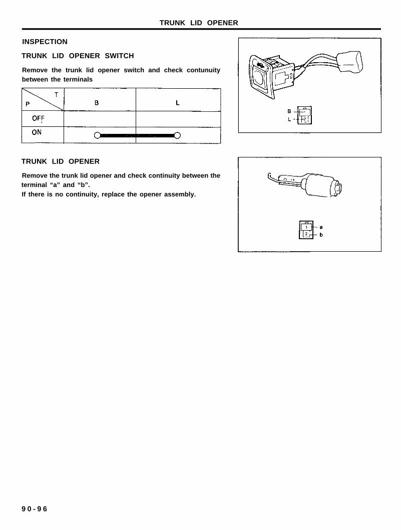
TRUNK LID OPENER
INSPECTION
TRUNK LID OPENER SWITCH
Remove the trunk lid opener switch and check contunuitybetween the terminals
TRUNK LID OPENER
Remove the trunk lid opener and check continuity between theterminal “a” and “b”.
If there is no continuity, replace the opener assembly.
9 0 - 9 6

E.T.A.C.S.
E.T.A.C.S. (Electronic Time and Alarm Control System)
SPECIFICATIONS
Items
Rated voltage
Operating voltage range
Voltage dropBefore durabilityAfter durability
Insulation resistanceOperating temperature rangeRated load
Variable intermittent wiperRear defogger timer
Seat belt warningKey illumination & delay out room lamp
Door lock actuator (lock, unlock)Chime bell
Specifications
DC 12V
DC 9-16V
MAX. 0.25VMAX. 0.4V100 MD with 500V megger
- 3 0 ~ +80°C (-22 ~ +176°F)
DC 12V, 6A (Inductive load)DC 12V. 200mA (Inductive load)DC 12V, 1.2W (Lamp load)
DC 12V, 1.2W, 10W (Lamp load)DC 12V, 200mA (Inductive load)DC 13.5V. 350mA (Inductive load)
COMPONENTS
9 0 - 9 7

E.T.A.C.S.
INSPECTION
VARIABLE INTERMITTENT WIPER
1. Operating characteristic: Fig.12. Time specification
T1: MAX. 0.5 sec.T2: Time of wiper motor 1 rotation.
T3: 1.5±0.7 sec. (VR=Okn)-10.5+3 sec. (VR=50 k0
3. Variable resistance (VR) : 0~50 kfi
WASHER
1. Operating characteristic: Fig.22. Time specification
T1: 0.4~1.2 secT2: 2.0~4.7 sec
3. This function should be operated preferentially even thoughthe variable intermittent wiper is operating.
REAR DEFOGGER (HEATED) TIMER
1. Operating characteristic: Fig.3
2. Time specification
T1: MIN. 0.5 sec.
T1: 10±3 mm
SEAT BELT WARNING
1. Operating characteristic: Fig.42. Time specification
T1: 6±1 sec.
T2: MAX. 6±1 sec.
T3: 0.3±0.1 sec.
9 0 - 9 8

E.T.A.C.S.
DOOR LOCK ACTUATOR
1. Operating characteristic: Fig.52. Time specification
T1: 0.5 sec.
IGN KEY HOLE ILLUMINATION
1. Operating characteristic: Fig.62. Time specification
T1: 6 sec.
T2: 0~ sec.
DELAY OUT ROOM LAMP
1. Operating characteristic: Fig.72. Time specification
T1: 2 sec.
T2: 4 sec.T3: 0~4 sec.
DOOR WARNING
1. Operating characteristic: Fig.8
2. Time specificationT1: 0.3±0.1 sec.
9 0 - 9 9

E.T.A.C.S.
1. Operating characteristic: Fig. 9
2. Time specificationT1: 5 sec.
1. After tracing the problem to the control unit, replace it with
a new one. Check for proper operation.
2. If system operates properly, the original control unit is faulty.
Items
Rear window defogger (heated) switch
Rated voltageOperating forceInsulating resistance
Indicator lampRear window heated glass
Rated voltagePower comsumption
Specifications
Disconnect the defogger switch connector from the wiringharness. Operate the switch, and check the continuity between
the terminals
DC 12V0.3 ~ 1.0 kg
MIN. 5M0 (DC 500V megger)
1.2 W
DC 12V185 ± 10 W (per sheet)
If continuity is not as specified, replace the switch.
9 0 - 1 0 0

E.T.A.C.S.
PRINTED HEATER LINE CHECK
CAUTION,Wrap tin foil around the end of the voltmeter test lead to
prevent damaging the heater line. Apply finger pressure on thetin foil, moving the tin foil along the grid line to check for open
circuits.
1. Turn on the defogger switch and use a voltmeter to measure
the voltage of each heater line at the glass center point. Ifa voltage of approximately 6V is indicated by the voltmeter,
the heater line of the rear window is considered satisfactory.
2. If a heater line is burned out between the center point and(+) terminal, voltmeter indicates 12 volts.
3. If a heater line is burned out between the center point and
(-) terminal, the voltmeter indicates 0 volt.

E.T.A.C.S.
4. To check for open circuits, slowly move the test lead in thedirection that the open circuit seems to exist. Try to find a
point where a voltage is generated or changes to 0V. Thepoint where the voltage has changed is the open-circuitedpoint.
Defogger OFF
5. Use an ohmmeter to measure the resistance of each heater
line between a terminal and the center of a grid line and
between the same terminal and the center of one adjacentheater line after another. The section involving a brokenheater line indicates resistance twice as that in other section.
In the affected section, move the test lead to a position
where resistance sharply changes.
Repair
Provide the following items:
1. Conductive paint2. Paint thinner
3. Masking tape.
4. Silicone remover5. Thin brush
Wipe the glass adjacent to the broken heater line, clean withsilicone remover and attach the masking tape as shown.
Shake the conductive paint container well, and apply threecoats with a brush at intervals of about 15 minutes apart.
Remove the tape and allow sufficient time for drying before
applying power.For a better finish, scrape away excess deposits with a knifeafter completely dried. (allow 24 hours)
CAUTION
After repairing, clean the glass with a soft dry cloth or
wipe along the grid line with a slightly moistened cloth.
9 0 - 1 0 2

AUTOMATIC TRANSAXLE AND KEY LOCK CONTROL SYSTEM
AUTOMATIC TRANSAXLE AND KEY LOCK CONTROL SYSTEMSPECIFICATION
Items
Control unit
Rated voltageOperating voltage range
Operating temperature rangeRated load
A/T solenoidRated voltageRated current
Operating voltage rangeOperating temperature range
Operating forceInitial pull in force
Spring forceHolding force
Key lock solenoidOperating voltage range
Operating temperature rangeExciting currentOperating force
Pull in forceHolding force
Parking position switchRated loadOperating force
Operating temperature range
Specifications
DC 12VDC 9 ~ 16V
- 3 0 ° ~ +80°C (-22°F ~ +176°F)
MAX. 1A (A/T solenoid)MAX. 0.8A (Key lock solenoid)
DC 12V1A (MAX. 2A)
DC 9 ~ 16V
- 3 0 ° ~ +80°C (-22°F ~ +176°F)
0.4 kg.cm (at 12V, 20°C)
0.2 kg.cm (at 12V, 20°C)1.5 kg.cm (at 12V, 20°C)
DC 9 ~ 16V
-30° ~ +80°C (-22°F ~ +176°F)
MAX. 0.9A
MIN. 0.17 kg.cm (at DC 7.5 ± 0.1V)
MIN. 0.25 kg.cm (at DC 6 ± 0.1V)
1A (resistance load, at DC 12V)0.8 ± 0.2 kgf- 3 0 ° ~ +80°C (-22°F ~ +176°F)
9 0 - 1 0 3

AUTOMATIC TRANSAXLE AND KEY LOCK CONTROL SYSTEM
COMPONENTS LAYOUT
A. Below front of center consoleB. Shift lever assemblyC. Ignition keyD. Shift lever assembly
A. Control unit B. A/T solenoid
C. Key lock solenoid D. P/position switch
9 0 - 1 0 4

AUTOMATIC TRANSAXLE AND KEY LOCK CONTROL SYSTEM
SYSTEM CHECK
KEY LOCK SYSTEM
1. Check that the ignition key cannot be turned to “LOCK (OFF)”position, when the position of the shift lever is not in “P”
position.
2. Check that the ignition key turns to the “LOCK (OFF)”position, when the shift lever is set to the “P” position.
SHIFT LOCK SYSTEM
1. Check that under the following conditions, the shift levercannot be moved from the “P” position to any other position.
IGNITION KEY POSITION : “ON”BRAKE PEDAL : NOT DEPRESSED
BUTTON : PRESSED
2. Check that under the following conditions, the shift lever canbe moved from the “P” position to other position.
IGNITION KEY POSITION : “ON”BRAKE PEDAL : DEPRESSED
BUTTON : PRESSED

AUTOMATIC TRANSAXLE AND KEY LOCK CONTROL SYSTEM
INSPECTION
TIMING CHART
AUTOMATIC TRANSAXLE SOLENOID
1. Remove the solenoid connector.
2. Using an ohmmeter, measure the resistance between
terminals.
Standard resistance : 12-16fi
3. Attach the positive (+) lead from the battery to terminal 1.and the negative (-) lead to terminal 2.
4. Check that an operation noise can be heard from thesolenoid.
9 0 - 1 0 6

AUTOMATIC TRANSAXLE AND KEY LOCK CONTROL SYSTEM
KEY LOCK SOLENOID
1. Remove the solenoid connector.2. Using an ohmmeter, measure the resistance between
terminals.
Standard resistance : 12.5-1 6.5R
3. Attach the positive (+) lead from the battery to terminal 2.and the negative (-) lead to terminal 1.
4. Check that an operating noise can be heard from thesolenoid.
9 0 - 1 0 7