Embed Size (px)
Citation preview

BOGERT HMMWV LIFTING JACK KIT
PART NR: 30M-HVBMI NSN: 5120-01-573-3382
Tire Replacement Jack Operating Instructions Model: 30M-HV Jack with BMI P40A Hydraulic Pump
Bogert International Inc. 3606 N. Swallow Ave., Suite 300
Pasco, WA 99301
Contact: Bogert International Inc. Office Phone Number: (509) 736-1512
Email: [email protected]
Copyright © 2009 Bogert International Inc. All Rights Reserved. Page 1 HMMWV Manual Part NR 30M-HVM, Rev C, Dated 14MAY2009

Bogert 30M-HV Jack & BMI P40A Hydraulic Pump Tire Replacement Jack Operating Instructions
Operating Instructions to change one tire at a time with the 30M-HVBMI Kit. It is not to be used for any other purpose.
Applicable to HMMWV FOV
TO PREVENT SERIOUS INJURY, READ AND UNDERSTAND ALL WARNINGS AND INSTRUCTIONS BEFORE USE.
Bogert International Inc. 3606 N. Swallow Ave., Suite 300
Pasco, WA 99301 Contact: Bogert International Inc.
Office Phone Number: (509) 736-1512 Email: [email protected]
Technical questions and replacement parts: 1-800-627-8088 in the US or (509) 736-1512
Latest Version of Manual and FAQ available at www.hmmwvjack.com
Copyright © 2009 Bogert International Inc. All Rights Reserved. Page 2 HMMWV Manual Part NR 30M-HVM, Rev C, Dated 14MAY2009

Table of Contents
Page 1.0 GENERAL SYSTEM DESCRIPTION 4 2.0 WARNING SUMMARY 5 3.0 GENERAL SAFETY INFORMATION 6 4.0 OPERATING INSTRUCTIONS 7 5.0 RECEIVING AND GENERAL JACK INFORMATION 12 6.0 INSPECTION, MAINTENANCE, AND CLEANING 14 7.0 SAFETY LABELS ON JACK 15 8.0 WARRANTY 15
9.0 REVISION CONTROL ________________________________________ 16
Copyright © 2009 Bogert International Inc. All Rights Reserved. Page 3 HMMWV Manual Part NR 30M-HVM, Rev C, Dated 14MAY2009

1.0 General System Description
The 30M-HVBMI KIT consists of an AISI 4130 steel frame hydraulic lifting jack with a 10 ton, 6.75” travel hydraulic ram (53.4 lbs), an 8”x18” jack bearing plate (5.4 lbs), and a hydraulic hand pump with a 6-foot hose extension (11.6 lbs), and a carry bag (4.2 lbs) for a combined total kit weight of 74.6 lbs.
The jack is designed to lift the HMMWV FOV at the upper most shock mounting bolt on the underside of the lower control arm, a lift point common to the HMMWV FOV.
The jack has a minimum lifting height of 5.75 inches and a maximum lift height of 20.75 inches, providing more than 14 inches of available lifting power stroke. The jack has been tested in the mud, sand, wet sand and on gravel slopes with a compound longitudinal and lateral grade of 7 percent.
30M-HVBMI KIT PERFORMANCE SPECIFICATIONS
Specification PerformanceVehicle platform Applicable to the HMMWV FOV Lift point At the upper most shock mounting bolt on the underside of the
lower control arm, a lift point common to all HMMWVs.Jack type HydraulicMax pump operating pressure 7000 psiMax operating force on pump handle 54 lbs (18 inch handle length)Lifting load rated capacity 4.25 tons (8500 lbs)Minimum lifting height 5.75 inchesMaximum lifting height 20.75 inchesTotal vertical lifting stroke More than 14 inchesGround pressure @ rated load of 7200 lbs
50 psi
Base Plate ground contact area 150 in2
Dimensions – 30M-HMMWV Jack 27.5” long x 9.75” wide x 6.0” highWeight – 30M-HMMWV JACK 53.4 lbsWeight – 30M-HVB Base Plate 5.4 lbsWeight – 30M-HVC Carry Bag 4.2 lbsWeight – 30M HVP & 30M-HV6 11.6 lbsLongitudinal slope lifting capability 7 %Side slope lifting capability 7 %Rated Endurance Minimum of 100 lifts @ rated load*
*Note that the jack was tested to the Safety Standard for Portable Automotive Lifting Devices, ASME PALD-2005, recommended procedure 5-4.1-4, compound slope stability test followed by 104 lifts (full travel) on a hard, level surface at the jack rated load. The jack was then subjected to an additional ASME PALD recommended procedure 5-4.1-4, compound slope stability test.
Copyright © 2009 Bogert International Inc. All Rights Reserved. Page 4 HMMWV Manual Part NR 30M-HVM, Rev C, Dated 14MAY2009
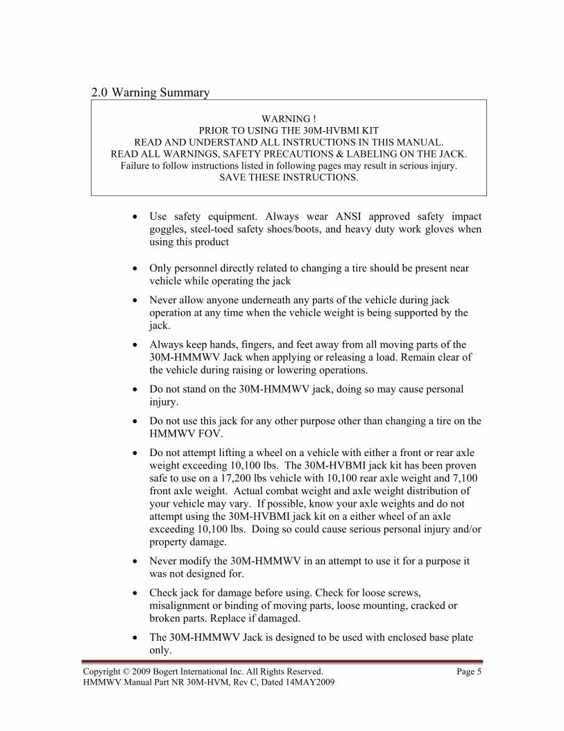
2.0 Warning Summary
WARNING ! PRIOR TO USING THE 30M-HVBMI KIT
READ AND UNDERSTAND ALL INSTRUCTIONS IN THIS MANUAL. READ ALL WARNINGS, SAFETY PRECAUTIONS & LABELING ON THE JACK.
Failure to follow instructions listed in following pages may result in serious injury. SAVE THESE INSTRUCTIONS.
• Use safety equipment. Always wear ANSI approved safety impact goggles, steel-toed safety shoes/boots, and heavy duty work gloves when using this product
• Only personnel directly related to changing a tire should be present near
vehicle while operating the jack
• Never allow anyone underneath any parts of the vehicle during jack operation at any time when the vehicle weight is being supported by the jack.
• Always keep hands, fingers, and feet away from all moving parts of the 30M-HMMWV Jack when applying or releasing a load. Remain clear of the vehicle during raising or lowering operations.
• Do not stand on the 30M-HMMWV jack, doing so may cause personal injury.
• Do not use this jack for any other purpose other than changing a tire on the HMMWV FOV.
• Do not attempt lifting a wheel on a vehicle with either a front or rear axle weight exceeding 10,100 lbs. The 30M-HVBMI jack kit has been proven safe to use on a 17,200 lbs vehicle with 10,100 rear axle weight and 7,100 front axle weight. Actual combat weight and axle weight distribution of your vehicle may vary. If possible, know your axle weights and do not attempt using the 30M-HVBMI jack kit on a either wheel of an axle exceeding 10,100 lbs. Doing so could cause serious personal injury and/or property damage.
• Never modify the 30M-HMMWV in an attempt to use it for a purpose it was not designed for.
• Check jack for damage before using. Check for loose screws, misalignment or binding of moving parts, loose mounting, cracked or broken parts. Replace if damaged.
• The 30M-HMMWV Jack is designed to be used with enclosed base plate only.
Copyright © 2009 Bogert International Inc. All Rights Reserved. Page 5 HMMWV Manual Part NR 30M-HVM, Rev C, Dated 14MAY2009

• Do not use the jack if any of the parts are damaged or not operational.
• Position the jack to lift only a single wheel station at a time. Do not use multiple jacks or lifting means to raise more than one wheel at a time.
• Jack service must be performed only by qualified personnel. Service performed by unqualified personnel could result in a risk of injury.
• Do not attempt to lift the vehicle on a side or longitudinal slope greater than 7% as per specification sheet.
• Do not use the jack to support a vehicle over extended periods of time. The duration of the lifting task should be kept to a minimum. Always use jack stands to support a vehicle over an extended period of time.
The warnings, precautions, and instructions discussed in this manual cannot cover all possible conditions and situation that may occur. The operator must understand that common sense and caution are factors, which cannot be built into this product, but must be supplied by the operator.
3.0 General Safety Information
3.1 Inspect the jack before each use. Verify that parts are not worn, bent or missing. If so, do not use the jack. Obtain replacement jack.
3.2 Do not modify or weld to the jack.
3.3 Do not use it for anything other than its intended purpose of lifting a wheel to change a tire on the HMMWV FOV.
3.4 Always lift at the designated lift point identified in this manual, the upper most shock mounting bolt on the underside of the lower control arm, a lift point common to all HMMWVs. Failure to do so will result in damage to the jack or serious injury or death to personnel.
3.5 Ensure that all air is purged from the hydraulic pump and jack before initial use. Refer to Section 8.0 for jack maintenance & purging instructions. If, after purging the jack still does not appear to be working properly, do not use the jack. Replace jack.
Copyright © 2009 Bogert International Inc. All Rights Reserved. Page 6 HMMWV Manual Part NR 30M-HVM, Rev C, Dated 14MAY2009

4.0 OPERATING INSTRUCTIONS
The following instructions are a general guideline for hydraulic hand pumps. They do not replace the operation or service manual for the enclosed pump.
IMPORTANT! Prior to its first use, make sure to check for proper hydraulic oil level in the external pump. Then thoroughly test the 30M-HMMWV jack for proper operation prior to its actual use.
If the 30M-HMMWV Jack appears not to be working properly, it may be necessary to bleed its hydraulic system of excess air. To do so, simply pump the pump handle until the hydraulic cylinder on the 30M-HMMWV has extended at least 3 inches. Tip the jack up on its nose until the hose fitting is pointing up. Release the pump valve. Compress the jack forcing any air back to the pump. Then check pump fluid level. CAUTION: If, after purging, the jack still does not appear to be working properly, do not use the Jack until it has been repaired by a qualified service technician.
WARNING: Do not allow anyone in the vehicle while using the 30M-HMMWV jack to replace a tire. Sudden movements and weight shift can result in instability. Keep all personnel a safe distance away from the vehicle.
WARNING: Never allow anyone underneath any parts of the vehicle during jack operation at any time when the vehicle weight is being supported by the jack. Failure to follow this instruction can result in severe injury or death to personnel
WARNING: Do not attempt to lift the vehicle on a side or longitudinal slope greater than 7% grade. The vehicle can slide or roll causing severe injury or death to personnel.
WARNING: Before lifting, place the vehicle’s transmission in “PARK”. Set the vehicle’s emergency brake. Then, block the wheel diagonal to the wheel that is being lifted, with the wheel chocks. Failure to follow this instruction can result in severe injury or death to personnel.
Chock Wheel – Diagonal to tire being changed
4.1 Use two wheel chocks on the tire diagonal to the tire being changed. For example, when changing the right rear tire, chock the front left tire
4.2 Sandwich the tire between the wheel chocks by placing one block in front and one block behind tire. Figure 4.1 Wheel chocks are not supplied in
30M-HVBMI Jack Kit
Copyright © 2009 Bogert International Inc. All Rights Reserved. Page 7 HMMWV Manual Part NR 30M-HVM, Rev C, Dated 14MAY2009

Check Clearance.
4.3 The base plate is equipped with a gauge built into each end of the plate.
4.4 Slide the base plate under the A-arm bolt and stand the base plate up under the A-arm bolt. A level surface ensures proper engagement with the vehicle lift point.
Note: When the wheel/tire is extremely low on a level soft-soil surface, the minimum clearance required can be attained by trenching a spot for the jack to sit. Remove sand mud etc. by trenching a level spot. It may be easier to trench a spot first, then back up/drive forward over the trench.
4.5 Recheck for minimum clearance.
Connect the Jack to the Pump. 4.6 Turn the release valve on the hydraulic pump a ½ turn counter clockwise to
release any pressure before attempting connection to the jack.
4.7 Locate the 6 foot hydraulic hose and wipe any dirt, sand, snow etc from the hydraulic fitting on the end of the hose. Also wipe any debris from the hydraulic fitting on the jack coupler.
4.8 Attach the 6 foot hose between the jack and pump by pushing the fittings together.
Lower the Jack Completely.
4.9 Check to make sure the 30M-HMMWV jack is fully lowered.
Note: The jack, hose and pump will need to be assembled to lower jack. If they are not attached, the hydraulic fluid can not move from the jack to the pump, allowing the jack to fully lower.
CAUTION!: The release valve on the hydraulic pump controls the release of the hydraulic fluid causing the jack to lower. Opening this valve too quickly will cause the vehicle to suddenly drop.
Copyright © 2009 Bogert International Inc. All Rights Reserved. Page 8 HMMWV Manual Part NR 30M-HVM, Rev C, Dated 14MAY2009

4.10 To lower jack, S-L-O-W-L-Y turn release valve on the hydraulic pump counter clockwise not more than one full turn to release any pressure on the pump. Then press down on the saddle of the jack to lower it to the fully retracted position.
Note: The saddle is the cup that makes the connection to the vehicle.
Position Jack and Base Plate Unit.
Figure 4.12 Pull back on plunger to set jack .
4.11 If clearance has not already been checked, see step 3.
4.12 Seat the nose of the jack into the base plate by pulling back on the base plate plunger then setting the front of the jack into the angle iron slot. Release the plunger.
WARNING!: Always maintain a safe distance
from the vehicle (minimum of 3 ft) during lift and lower operations.
4.13 The jack must be in-line, parallel with the axle of the vehicle.
Note: Jack should be positioned in-line with the vehicle axle to ensure the jack’s saddle and vehicle lifting points are in alignment. If not, remove and reposition the jack before lifting the vehicle.
Figure 4.13 Position Jack in line with vehicle axle. (Parallel)
Figure 4.14 Recommended lifting point.
4.14 Position the saddle of the jack under the recommended lifting point which is at the upper most shock mounting bolt on the underside of the lower control arm.
Copyright © 2009 Bogert International Inc. All Rights Reserved. Page 9 HMMWV Manual Part NR 30M-HVM, Rev C, Dated 14MAY2009

4.15 Close external pump valve by turning it clockwise . Note: The hose end of the hydraulic pump should be level with or slightly lower than the dip stick end of the pump to assure oil flow.
4.16 Pump the handle on the external pump until the Jack’s saddle has nearly reached the vehicle lifting point. Note: The pump can also be operated by holding on to the pump reservoir with one hand and the handle with the other, while the hose end is pointed down.
4.17 Check to see that the saddle has full capture on the lift point. If not, lower or raise the jack as required to reposition the jack to ensure full engagement between the saddle of the jack and the vehicle lift point.
4.18 Prior to lifting the vehicle, slightly l-o-o-s-e-n, but do not remove the 8 lug nuts (7/8”) on the affected wheel.
Jacking Up the Vehicle.
4.19 To lift the vehicle, pump the handle on the external pump. Use smooth, full strokes for best results.
4.20 Raise the vehicle just enough to remove the damaged tire, finish removal of the lug nuts and remove the damaged tire.
WARNING!: Never use the jack to raise a fully inflated replacement tire more than 2 inches off the ground. For a flat or destroyed tire, only raise the vehicle enough to install the replacement tire.
WARNING!: Do not use the Jack to support a vehicle over extended periods of time. The duration of the lifting task should be kept to a minimum, just long enough to replace a tire. Always use jack stands to support a vehicle over an extended period of time. Failure to follow this instruction can result in severe injury or death to personnel.
4.21 Install the replacement tire and tighten the lug nuts. There may be a need to raise the vehicle higher to install the replacement tire. Adjust the jack height to align these holes and the tire will go on much easier.
HMMWV Manual Part NR 30M-HVM, Rev C, Dated 14MAY2009
Follow the tightening sequence to the right.
USER NOTE: It is much easier to install the replacement tire if the wheel studs are at the same height as the replacement tire bolt holes.
4.22 Ensure all tools and personnel are clear from beneath the vehicle. Ensure hydraulic hose is clear of wheel being lowered. As soon as possible notify unit maintenance to tighten lug nuts to proper torque.
Copyright © 2009 Bogert International Inc. All Rights Reserved. Page 10

4.23 S-L-O-W-L-Y turn the pump valve control release knob counter clockwise to lower the vehicle on to the ground. Rock the base plate up by lifting up at the base plate handle and then release. This will compress the jack enough to remove the jack from its lift point.
Note: Never allow the jack to lower suddenly. Slowly and carefully lower the load with your hand covering the pump valve control release knob in the event the lowering process must be halted. To stop the vehicle from lowering, turn the pump valve release knob clockwise to tighten.
Lower the 30M-HMMWV jack completely.
4.24 Disconnect the hose from the 30M-HMMWV jack. To disconnect the hose, locate the rotating collar connected to the jack cylinder fitting. Line up the u-shaped slot to the pin. Then depress the slot into the pin to release the fitting
4.25 Remove wheel chocks from the tire diagonal to the tire just changed.
4.26 Store the jack, pump, hose and wheel chocks in their designated locations on the vehicle.
Copyright © 2009 Bogert International Inc. All Rights Reserved. Page 11 HMMWV Manual Part NR 30M-HVM, Rev C, Dated 14MAY2009

5.0 RECEIVING AND GENERAL JACK INFORMATION
Ensure that no parts were damaged during shipping. Inventory the jack kit to ensure that all parts comprising the kit have been included.
The 30M-HVBMI Kit NSN 5120-01-573-3382 includes: PN 30M-HVM One Manual for the 30M-HV Kit PN 30M-HMMWV One 30M-HMMWV Tire Replacement Jack. PN 30M-HVB One base plate. PN 30M-HVP One external hydraulic pump and pump handle. PN 30M-HV6 One 6-foot hydraulic hose with couplings PN 30M-HVC One carry bag for all components above.
No maintenance should be needed on this jack, with the exception of possibly tightening screws or wiping debris from the jack after use. If any parts are missing or broken, call Bogert International Inc. at 1+509-736-1512 or email [email protected]. If any questions arise with any of the procedures outlined in this manual or in general or safety related questions in using this jack, please contact Bogert International Inc. at telephone number 1+509-736-1512 or email [email protected].
Copyright © 2009 Bogert International Inc. All Rights Reserved. Page 12 HMMWV Manual Part NR 30M-HVM, Rev C, Dated 14MAY2009

6.0 INSPECTION, CLEANING & MAINTENANCE WARNING!
All maintenance, service, or repairs not listed in this manual are only to be attempted by a qualified service technician.
If a problem occurs, have the problem corrected before further use.
CAUTION: Maintain labels and nameplates on the 30M-HMMWV Jack. These carry important information. If unreadable or missing, contact Bogert International Inc. for a replacement.
6.1 INSPECTION
6.1.1 Check for broken, cracked or bent parts. Do not use if broken, cracked or bent.
6.1.2 Check for loose or missing parts. Tighten as required.
6.1.3 Check welds and any condition that may affect the proper operation.
6.1.4 Check hose for damage.
6.1.5 Check for leaky fittings.
6.2 CLEANING 6.2.1 Use clean cloth with mild detergent to wipe debris.
6.2.2 Do not use chemicals to clean the 30M-HMMWV Jack or components.
6.3 MAINTENANCE 6.3.1 Purge Jack and Hose
6.3.1.1 To purge jack and hose simply pump the pump handle until the hydraulic cylinder on the 30M-HMMWV has extended at least 3 inches. Tip the jack up on its nose until the hose fitting is pointing up. Turn the pump release ½ turn counter clockwise. Compress the jack forcing any air back to the pump. Turn release valve clockwise to close.
6.3.2 Fill Hydraulic Pump to Full Mark
6.3.2.1 The following is only a guide. Refer to pump manual for proper instructions. Check Pump Fluid Level. Check the pump fluid level by holding the pump with the hose end pointing down. Use a wrench to remove the uppermost bolt in the pump end cap. The dip stick is attached to this plug. Remove the dip stick and wipe the oil from the stick. Replace the dip stick. Then remove
Copyright © 2009 Bogert International Inc. All Rights Reserved. Page 13 HMMWV Manual Part NR 30M-HVM, Rev C, Dated 14MAY2009

and check dipstick for oil. If oil is present on the stick, there is enough oil to operate the jack. If no oil is present add MIL PRF-46170D. In an emergency, any light oil will work.
6.3.3 Tighten Loose Screws
6.3.3.1 Use Philips Head screw driver to hand-tight
6.3.4 Tighten Hydraulic Fittings
6.3.4.1 Use appropriate size wrench to tighten leaking or loose fittings.
6.3.5 Replace Damaged Hydraulic Fittings
6.3.5.1 Use appropriate size wrench to remove damaged fitting
6.3.5.2 Use Teflon tape on all pipe threads. (2-4 wraps)
6.3.5.3 Tighten to below specifications.
6.3.5.3.1 Swivel to Jack 360 inch lbs. or 30 foot lbs.
6.3.5.3.2 Coupling to Swivel 360 inch lbs. or 30 foot lbs.
6.3.5.4 Check for operation.
6.3.5.5 Tighten as necessary to ensure there are no leaks.
6.3.6 Replace Damaged Hose Assembly
6.3.6.1 Use appropriate size wrench to remove damaged hose fitting
6.3.6.2 Use Teflon tape on all pipe threads. (2-4 wraps)
6.3.6.3 Tighten to below specifications.
6.3.6.3.1 Hose to Pump 240 inch lbs. or 20 foot lbs.
6.3.6.3.2 Hose to Coupling 240 inch lbs. or 20 foot lbs.
6.3.6.4 Check for operation.
6.3.6.5 Tighten as necessary to ensure there are no leaks.
6.4 PERIODIC MAINTENANCE 6.4.1 Once a month, make sure to thoroughly test the 30M-HVBMI Kit
for proper operation.
6.4.2 Change the MIL-PRF-46170D hydraulic fluid at least once every year. To do so, refer to the proper manual that came with the external pump.
Copyright © 2009 Bogert International Inc. All Rights Reserved. Page 14 HMMWV Manual Part NR 30M-HVM, Rev C, Dated 14MAY2009

7.0 SAFETY LABELS ON JACK
Sample labels below. It will be located on the top-center side of the cylinder of 30M-HMMWV.
8.0 WARRANTY
Bogert International Inc. is your warranty agent for any and all items in the 30M-HVBMI Jack Kit. All components are warranted to be free of defects in materials and workmanship and carry a one year parts and labor warranty when used in accordance with the operating instructions and limitations. Any product that does not conform to specifications will be repaired or replaced. This warranty does not cover ordinary wear and tear, abuse, misuse, alterations, or the use of improper fluids. Determination of the authenticity of a warranty claim will be made only by Bogert International Inc. and original manufacturer of the warranty item. Contact Bogert International Inc. 3606 N. Swallow Ave, Suite 300, Pasco, WA 99301. Phone Number: (509) 736-1512, Facsimile: (509) 272-0280. Email: [email protected]
Copyright © 2009 Bogert International Inc. All Rights Reserved. Page 15 HMMWV Manual Part NR 30M-HVM, Rev C, Dated 14MAY2009

NOTES
Copyright © 2009 Bogert International Inc. All Rights Reserved. Page 16 HMMWV Manual Part NR 30M-HVM, Rev C, Dated 14MAY2009