Embed Size (px)
Citation preview
GF-108 OMM-0011_0A
Boiler Management system (BMS) g y ( )USER MANUAL
BOILER MANAGEMENT SYSTEM

GF-108 OMM-0011_0A
Boiler Management system (BMS) g y ( )USER MANUAL
i
GF-108 OMM-0011_0A
Boiler Management system (BMS) g y ( )USER MANUAL
Table of Contents
SECTION 1 ABOUT YOUR NEW BOILER MANAGEMENT
Page
SYSTEM (BMS) 1-1
SECTION 2 FEATURES OF THE BMS 2-1
SECTION 3 INSTALLING THE BMS 3-13.1 MOUNTING THE BMS 3-13.2 GENERAL WIRING 3-1
3.2.1 Pulse Width Modulation Wiring At the BMS 3-23.2.2 Pulse Width Modulation Wiring At the Boiler 3-2
3.3 SENSOR INSTALLATION AND WIRING 3-33.3.1 Header Sensor 3-33.3.2 Outside Air Sensor 3-3
SECTION 4 FAMILIARIZING YOURSELF WITH THE BMS 4-14.1 ABOUT BMS MODES 4-1
4.1.1 Selecting and Viewing Functions 4-14,1,2 Changing Function Settings 4-1
4.2 NORMAL MODE FUNCTIONS 4-44.2.1 HDR TEMP 4-44,2,2 AIR TEMP 4-44.2.3 % LOAD 4-44.2.4 SYS START TEMP 4-44.2.5 REF TEMP 4-44.2.6 HDR TEMP LIMIT 4-44.2.7 FIELD ADJ 4-44.2.8 SET POINT 4-44.2.9 PROP BAND 4-44.2.10 OFF SET 4-44.2.11 RESET RATIO 4-44.2.12 and Arrow Keys 4-54.2.13 ON and OFF Keys 4-54.2.14 CONFIG SYS 4-5
4.3 FIELD ADJUST MODE FUNCTIONS 4-54.3.1 HDR TEMP 4-54.3.2 AIR TEMP 4-54.3.3 % LOAD 4-54.3.4 Setting the Internal Clock With the % LOAD Key 4-54.3.5 SYS START TEMP 4-64.3.6 REF TEMP 4-64.3.7 HDR TEMP LIMIT 4-64.3.8 FIELD ADJ 4-74.3.9 SET POINT 4-7
ii
GF-108 OMM-0011_0A
Boiler Management system (BMS) g y ( )USER MANUAL
Table of Contents (Continued)
4.3.10 PROP BAND 4-74.3.11 OFF SET 4-74.3.12 Setting Up a Reset Schedule 4-74.3.13 RESET RATIO 4-84.3.14 and Arrow Keys 4-84.3.15 ON and OFF Keys 4-84.3.16 CONFIG SYS 4-8
4.4 SYSTEM CONFIGURATION MODE FUNCTIONS 4-94.4.1 TEMP FAIL MODE 4-94.4.2 SYS ENABLE 4-104.4.3 MAX PWR INPUT 4-104.4.4 START AND STOP LEVEL Keys 4-104.4.5 BLR OP MODE 4-11
4.4.5.1 Sequential Mode 4-114.4.5.2 Parallel Mode 4-114.4.5.3 Combination Mode 4-114.4.5.4 Designating the Number of Combination Boilers 4-12
4.4.6 HDR SET MODE 4-124.4.7 INTGL RATE GAIN and DERIV GAIN Keys 4-12
4.4.7.1 TEMP BANDWIDTH 4-134.4.7.2 INTGL RATE GAIN 4-13
4.4.8 AUX RELAY 4-134.4.9 and Arrow Keys 4-144.4.10 ON and OFF Keys 4-144.4.11 CONFIG SYS 4-14
SECTION 5 PROGRAMMING THE BMS MODE OF OPERATION 5.1 INDOOR/OUTDOOR RESET MODE 5-1
5.1.1 Selecting Indoor/Outdoor Reset Mode 5-15.1.2 Entering System Start Temperature 5-15.1.3 Determining the Reset Schedule 5-15.1.4 Entering the Building Reference Temperature 5-25.1.5 Entering the Reset Ratio 5-2
5.2 SETUP FOR 4-TO-20-MA REMOTE SETPOINT MODE 5-25.2.1 Entering Header Set and Boiler Operating Modes 5-25.2.2 Entering Building Reference Temperature 5-2
5.3 SETUP FOR CONSTANT SETPOINT MODE 5-35.3.1 Entering Header Set and Boiler Operating Mode 5-35.3.2 Entering Header Reference Temperature 5-3
5.4 CONFIGURING THE TEMPERATURE CONTROLLER FOR PULSE WIDTH MODULATION 5-3
5.4.1 Temperature Controller Addressing 5-35.4.2 Configuring the Temperature Controller 5-4
iii
GF-108 OMM-0011_0A
Boiler Management system (BMS) g y ( )USER MANUAL
Table of Contents (Continued)
5.5 SYSTEM INITIALIZATION AND POLLING 5-45.6 TESTING THE SYSTEM 5-4
APPENDICES Appendix A Specifications A-1Appendix B Methods for Determining Reset Schedule
and Indoor/Outdoor Reset Ratio Charts B-1Appendix C Normal (Read-Only) Mode Display Messages
and Defaults C-1Appendix D Field Adjust Mode Display Messages and Defaults D-1Appendix E Config Sys Mode Display Messages and Defaults E-1Appendix F Sensor Resistance Data Sheet F-1Appendix G Parts List G-1Appendix H Troubleshooting H-1Appendix I General BMS Wiring I-1Appendix J Programming the BMS Using RS-232 Communication J-1
iv
GF-108 OMM-0011_0A
Boiler Management system (BMS) g y ( )USER MANUAL
List of Figures Figure 1 Typical BMS Installation 3-4Figure 2 BMS Mounting 3-5Figure 3 Wire Routing Locations at the BMS 3-6Figure 4 PWM Communication Outputs at the BMS 3-7Figure 5 Pulse Width Modulation Connections at KC Series Boiler
Boiler With Modular Control Box 3-8Figure 6 Pulse Width Modulation Connections at KC Series Boiler
Boiler With C-More Control Box 3-9Figure 7 Pulse Width Modulation Connections at the Benchmark
Boiler With Modular Control Box 3-10Figure 8 Pulse Width Modulation Connections at the Benchmark
Boiler With C-More Control Box 3-11Figure 9 Header Sensor Installation With Well 3-12Figure 10 Outside Air Sensor Mounting and Connections 3-13Figure 11 Normal and Field Adjust Mode Overlay 4-2Figure 12 System Configuration Mode Overlay 4-3
1-1
GF-108 OMM-0011_0A
Boiler Management system (BMS) g y ( )USER MANUAL
Section 1 ______________________________
About Your New Boiler Management System (BMS) AERCO’s Boiler Management System (BMS), stages and modulates AERCO KC Series and Benchmark boilers, allowing them to operate efficiently as a system. It provides a broad array of operating modes, so that the nuances of specific applications can be easily accommodated. The BMS will control eight boilers via pulse width modulation communication.
PRECISE CONTROL Utilizing Pulse Width Modulation (PWM), the BMS fully exploits the condensing and modulating ability and efficiency of each boiler and regulates the output of the boiler plant with water supply temperature variation of no more than ±2°F
Staging can be performed sequentially or in parallel. The BMS can sample building reference temperatures to modulate boiler plant output, and will perform water supply temperature night setback automatically referenced to its internal clock.
SIMPLE INSTALLATION AND OPERATION Installation of the BMS is simple, and low-voltage wiring is employed between the BMS panel and boiler modules. There are no complex design steps to be performed, since a keypad in conjunction with the LCD allows the operator to acquire, change, and program settings through easy-to-use labeled buttons. Each BMS function consists only of selecting the function and toggling values, which generally requires no more than pressing four keys.
The instant a parameter is programmed, it is automatically entered into the BMS memory, avoiding multiple programming steps to store information. In the event of power loss, most factory default settings remain in nonvolatile memory for up to 10 years and need not be reprogrammed. However, date and time remain in memory for about 30 days.
RS232 COMMUNICATION If desired, the BMS can be programmed by connecting a Laptop Computer, or other type of terminal emulation device, to the RS232 connector on the front panel. See Appendix J for programming using RS232 communication.
.

GF-108 OMM-0011_0A
Boiler Management system (BMS) g y ( )USER MANUAL
2-1
GF-108 OMM-0011_0A
Boiler Management system (BMS) g y ( )USER MANUAL
Section 2 ______________________________
Features of the BMS_____ APPLICATION FLEXIBILITY Three different system or control options can be selected at setup to match the needs of any closed-loop system - Indoor/Outdoor Reset, 4-to-20 mA Remote Setpoint, and Constant Setpoint.
CONTINUOUS COMMUNICATIONS The BMS continually sends information to the boilers and receives information from them, providing total control of boiler plant dynamics.
EXCEPTIONAL ACCURACY The BMS control system uses a PID (Proportional Integral Derivative) control algorithm to respond dynamically to system changes. Water temperatures are precisely controlled by modulating energy in put. A supply water temperature of ±2°F is assured.
BUILDING INDOOR AIR TEMPERATURE INPUTS The BMS accepts building indoor air temperatures directly from a thermistor sensor or from a 4-to-20 mA signal. Adjustments can be made to the header setpoint temperature to compensate for varying building temperatures and conditions.
SEQUENTIAL OR PARALLEL OPERATION Modules can be either sequenced on, or run in parallel, by selection from the front panel. In sequential mode, boilers are brought on one at a time, so turn-down ratio is 14 multiplied by the number of KC Series boilers, or 15 multiplied by the number of Benchmark boilers. This provides higher energy savings and seasonal efficiency. In parallel mode, all of the boilers are modulated together at the same firing rate. The turn-down ratio of the system is fixed at 14:1 for the KC Series boilers and 15:1 for the Benchmark boilers.
BUMPLESS TRANSFER When in sequential mode, the BMS stages boilers on and off, one at a time, at selectable percentages of firing rate. The result is a seamless transition and undetectable room temperature changes. Sequential mode has several other unique features:
Run-Time Equalization: The BMS sequences boilers on a first on-first off basis, which automatically equalizes the run time of all boilers in the plant.
Automatic Load Distribution: The BMS continuously monitors the number of modules that are available for operation. In the event of a boiler malfunction or when service is performed, the BMS automatically compensates for a lack of response from any unit and brings on the next available boiler to satisfy demand. This feature operates in both parallel and sequential modes.

2-2
GF-108 OMM-0011_0A
Boiler Management system (BMS) g y ( )USER MANUAL
Time Delay Between Boiler Starts: A fixed, 30-second time delay between boiler starts ensures smooth energy input without spikes in electrical, gas, or venting conditions.
AUTOMATIC SYSTEM START Automatic system start contacts for controlling auxiliary equipment such as pumps and dampers can be selected to close between 32°F and 100°F outside air temperature, eliminating the need for the plant operator to turn auxiliary equipment on and off.
MINIMUM AND MAXIMUM HEADER SET CLAMPING The supply water temperature can be clamped at a maximum high temperature or minimum low temperature, to ensure that the building temperature is optimal for the greatest comfort.
Two Interlock Circuits (Enable/Disable Contacts) The BMS contains two normally-open interlock circuits that require only a set of dry contacts to enable or disable the boiler plant. They can be used to monitor pumps, combustion air dampers, or other equipment. Out-of-limit conditions trip the interlocks, shutting down the boiler plant, and providing a high level of protection.
ADJUSTABLE OFFSET The Offset feature can allow the temperature of the supply water to be offset in 1° increments over a range of -50°F below to +50°F above its current temperature. This feature is employed for night setback or morning warmup. The BMS lets you select, over a 7-day period, the time when the offset begins and ends.
CONTROL OF AUXILIARY EQUIPMENTThe auxiliary relay uses a dry set of contacts to operate auxiliary equipment. For example, when the boiler plant is at 100% load, these contacts close and can start an auxiliary boiler, or notify an energy management system of a full-load condition.
FAULT ALARM SURVEILLANCE The BMS continually monitors its sensors for opens and shorts and the interlock circuits for opens. However, the BMS fault relay does not close or indicate when a boiler has failed. The alarm circuit consists of a dry set of 120 VAC contacts rated at 5 A.
SIMPLE INSTALLATION The BMS operates from 120 VAC, 50 to 60 Hz, and uses Belden 9841 or equivalent wiring between modules for control and monitoring. The lightweight panel can be mounted up to 200 feet from the boilers when using pulse width modulation communication.
RUGGED AND RELIABLE The BMS is housed in a NEMA 13-grade enclosure and operates in ambient temperatures as high as 131°F (55°C).
POWER-OFF MEMORY Most system configuration values are retained in nonvolatile memory for up to 10 years. Date and time remain in memory for approximately 30 days.
3-1
GF-108 OMM-0011_0A
Boiler Management system (BMS) g y ( )USER MANUAL
Section 3 ______________________________
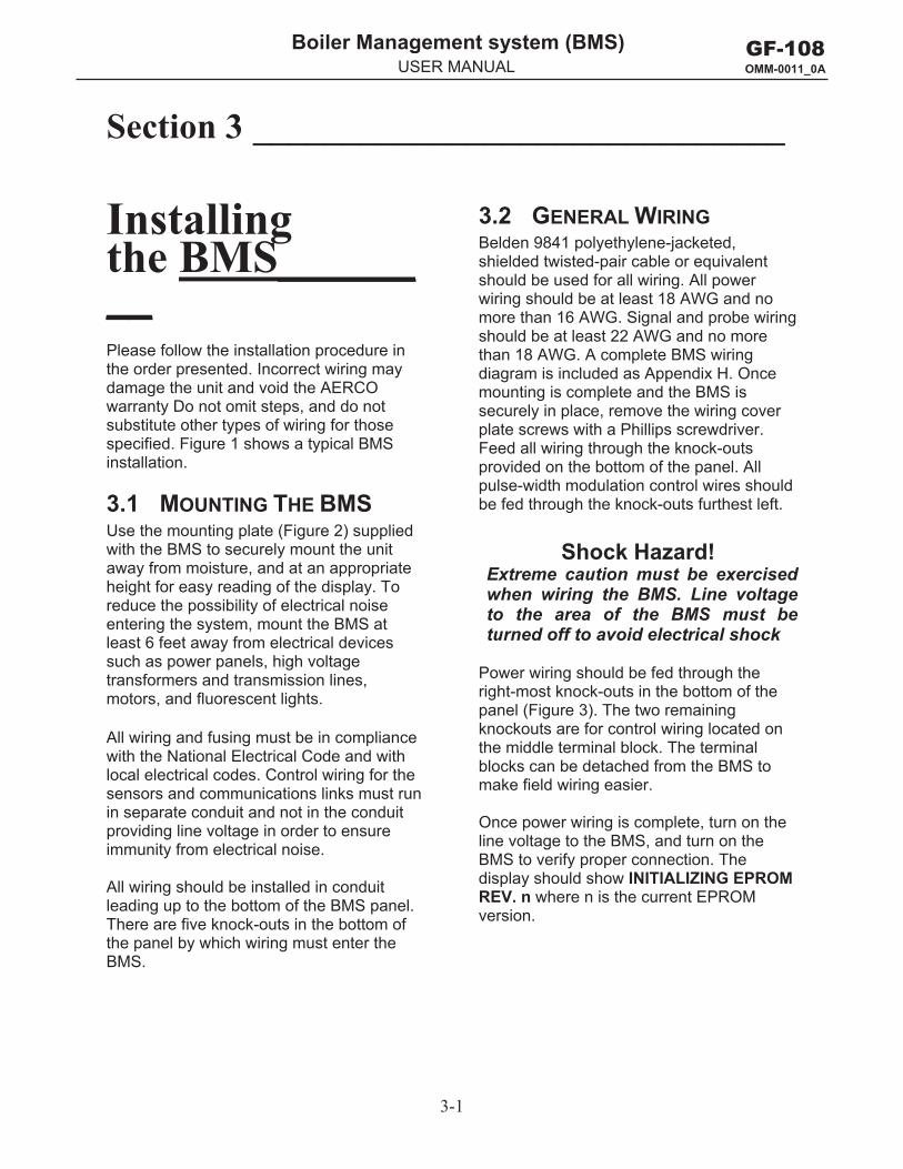
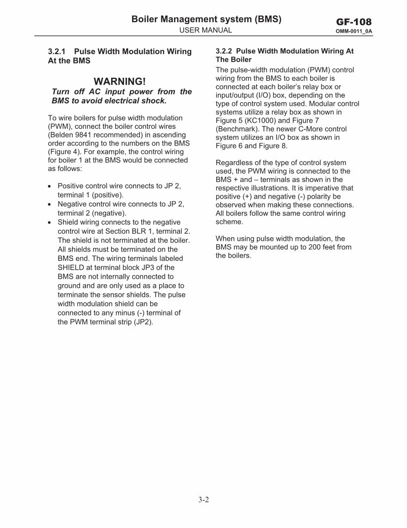
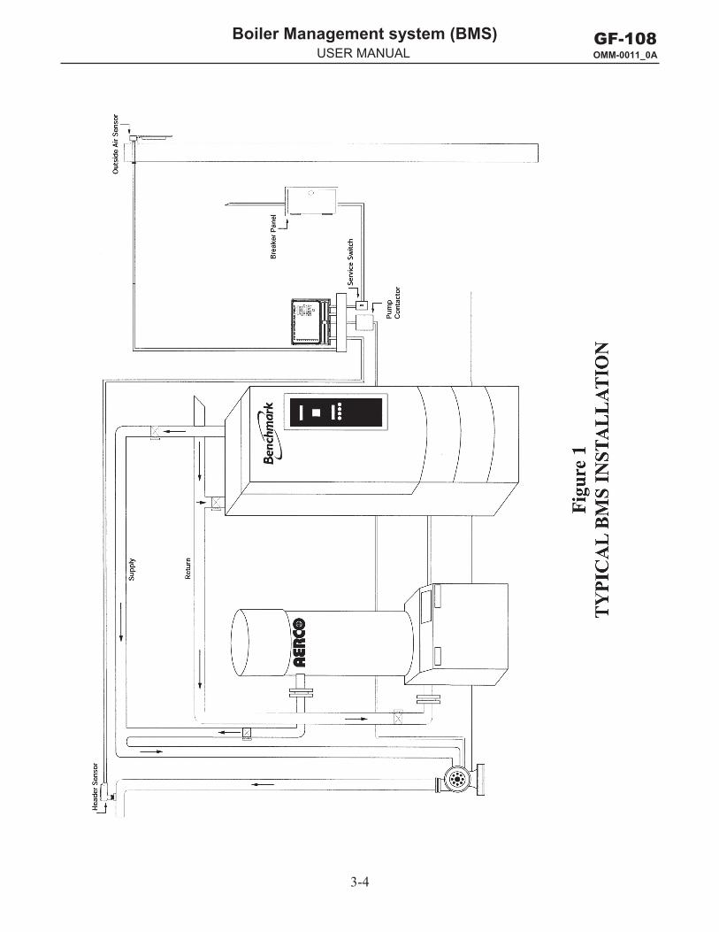
Installing the BMS________ Please follow the installation procedure in the order presented. Incorrect wiring may damage the unit and void the AERCO warranty Do not omit steps, and do not substitute other types of wiring for those specified. Figure 1 shows a typical BMS installation.
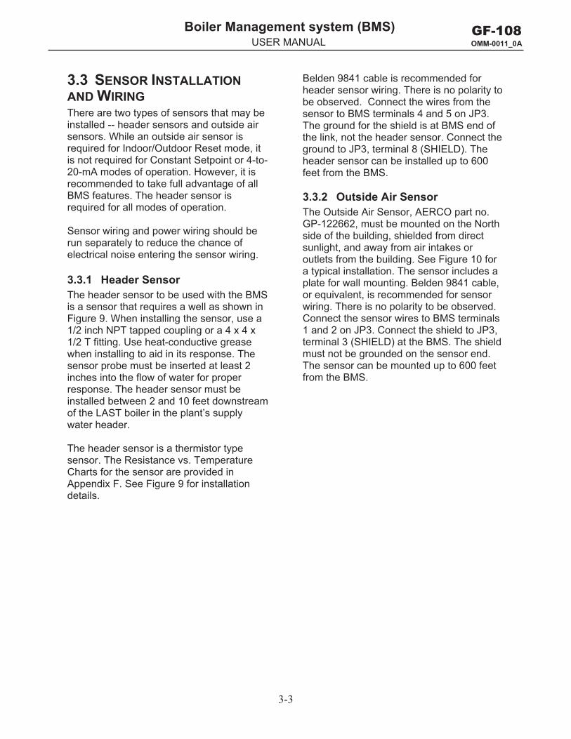
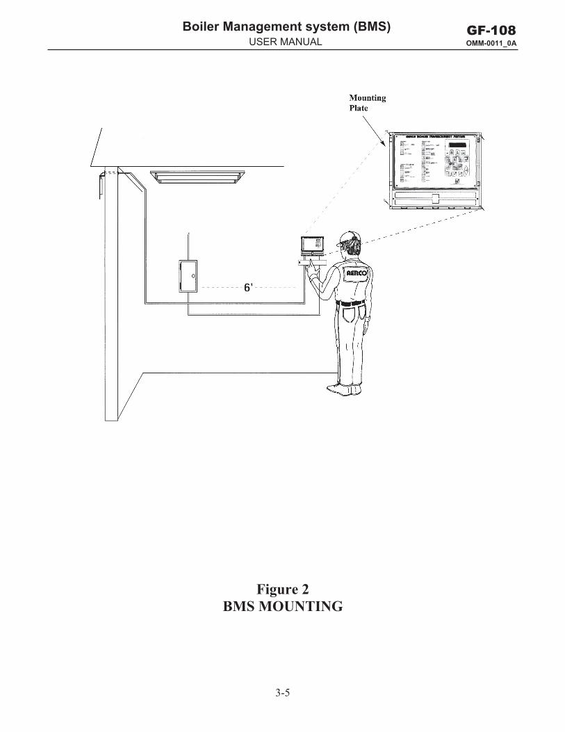
3.1 MOUNTING THE BMS Use the mounting plate (Figure 2) supplied with the BMS to securely mount the unit away from moisture, and at an appropriate height for easy reading of the display. To reduce the possibility of electrical noise entering the system, mount the BMS at least 6 feet away from electrical devices such as power panels, high voltage transformers and transmission lines, motors, and fluorescent lights.
All wiring and fusing must be in compliance with the National Electrical Code and with local electrical codes. Control wiring for the sensors and communications links must run in separate conduit and not in the conduit providing line voltage in order to ensure immunity from electrical noise.
All wiring should be installed in conduit leading up to the bottom of the BMS panel. There are five knock-outs in the bottom of the panel by which wiring must enter the BMS.
3.2 GENERAL WIRING Belden 9841 polyethylene-jacketed, shielded twisted-pair cable or equivalent should be used for all wiring. All power wiring should be at least 18 AWG and no more than 16 AWG. Signal and probe wiring should be at least 22 AWG and no more than 18 AWG. A complete BMS wiring diagram is included as Appendix H. Once mounting is complete and the BMS is securely in place, remove the wiring cover plate screws with a Phillips screwdriver. Feed all wiring through the knock-outs provided on the bottom of the panel. All pulse-width modulation control wires should be fed through the knock-outs furthest left.
Shock Hazard! Extreme caution must be exercised when wiring the BMS. Line voltage to the area of the BMS must be turned off to avoid electrical shock
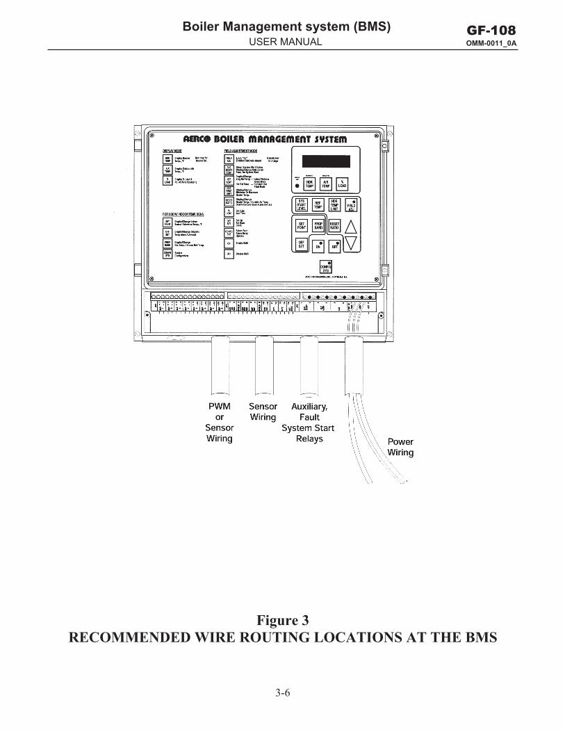
Power wiring should be fed through the right-most knock-outs in the bottom of the panel (Figure 3). The two remaining knockouts are for control wiring located on the middle terminal block. The terminal blocks can be detached from the BMS to make field wiring easier.
Once power wiring is complete, turn on the line voltage to the BMS, and turn on the BMS to verify proper connection. The display should show INITIALIZING EPROM REV. n where n is the current EPROM version.
3-2
GF-108 OMM-0011_0A
Boiler Management system (BMS) g y ( )USER MANUAL
3.2.1 Pulse Width Modulation Wiring At the BMS
WARNING! Turn off AC input power from the BMS to avoid electrical shock.
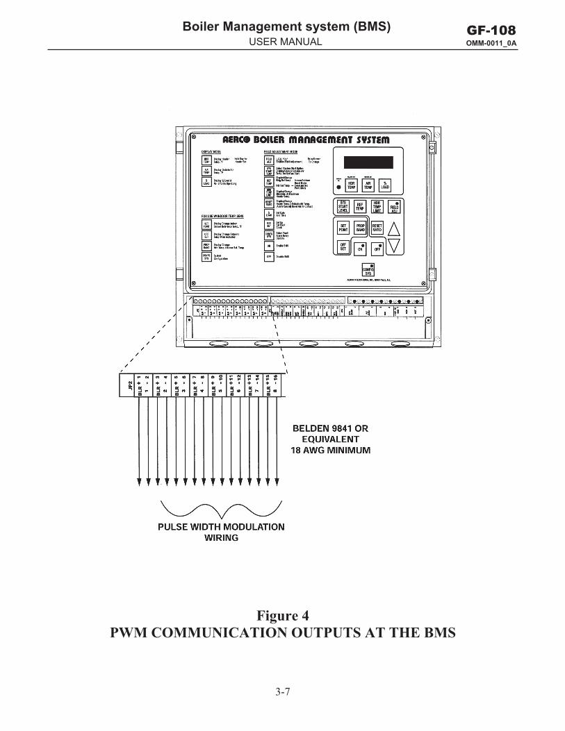
To wire boilers for pulse width modulation (PWM), connect the boiler control wires (Belden 9841 recommended) in ascending order according to the numbers on the BMS (Figure 4). For example, the control wiring for boiler 1 at the BMS would be connected as follows:
Positive control wire connects to JP 2, terminal 1 (positive).
Negative control wire connects to JP 2, terminal 2 (negative).
Shield wiring connects to the negative control wire at Section BLR 1, terminal 2. The shield is not terminated at the boiler. All shields must be terminated on the BMS end. The wiring terminals labeled SHIELD at terminal block JP3 of the BMS are not internally connected to ground and are only used as a place to terminate the sensor shields. The pulse width modulation shield can be connected to any minus (-) terminal of the PWM terminal strip (JP2).
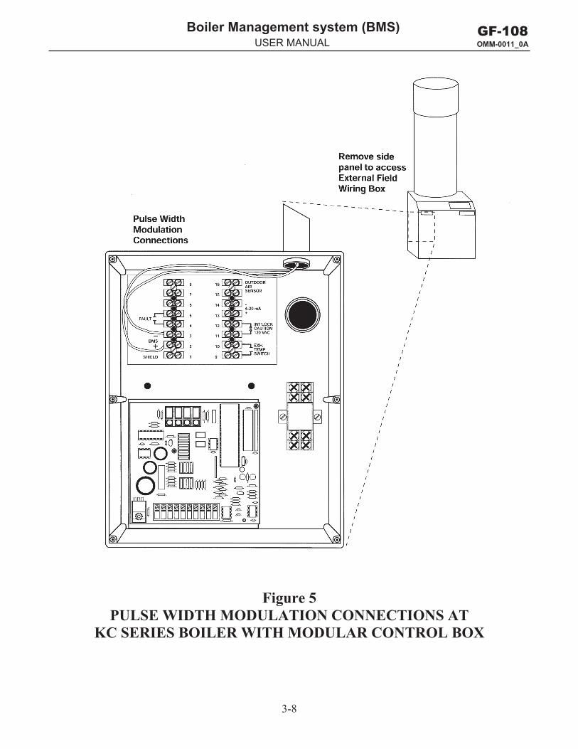
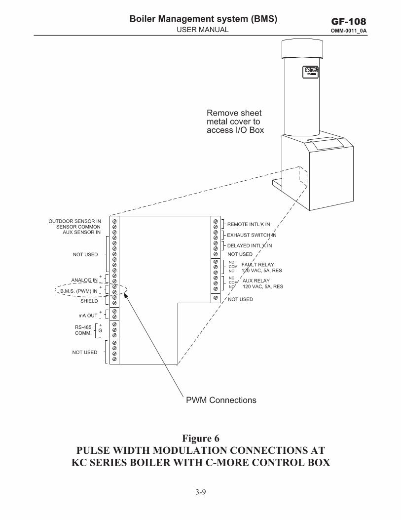
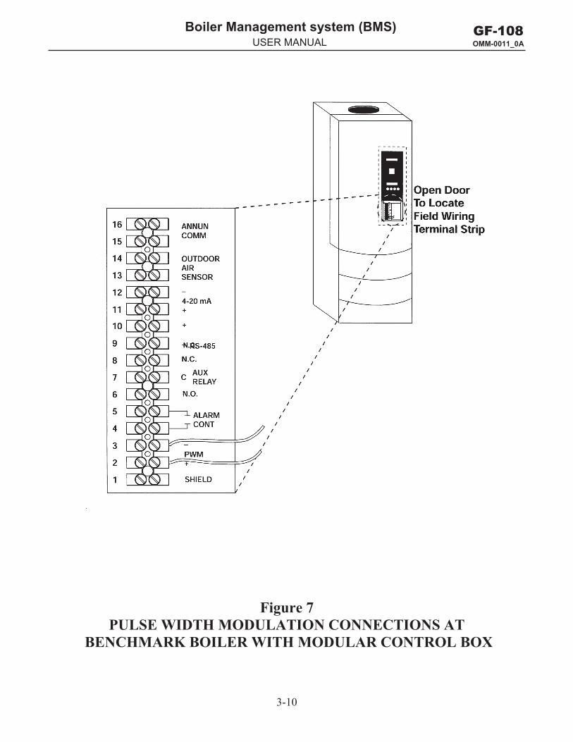
3.2.2 Pulse Width Modulation Wiring At The Boiler The pulse-width modulation (PWM) control wiring from the BMS to each boiler is connected at each boiler’s relay box or input/output (I/O) box, depending on the type of control system used. Modular control systems utilize a relay box as shown in Figure 5 (KC1000) and Figure 7 (Benchmark). The newer C-More control system utilizes an I/O box as shown in Figure 6 and Figure 8.
Regardless of the type of control system used, the PWM wiring is connected to the BMS + and – terminals as shown in the respective illustrations. It is imperative that positive (+) and negative (-) polarity be observed when making these connections. All boilers follow the same control wiring scheme.
When using pulse width modulation, the BMS may be mounted up to 200 feet from the boilers.
3-3
GF-108 OMM-0011_0A
Boiler Management system (BMS) g y ( )USER MANUAL
3.3 SENSOR INSTALLATION AND WIRING There are two types of sensors that may be installed -- header sensors and outside air sensors. While an outside air sensor is required for Indoor/Outdoor Reset mode, it is not required for Constant Setpoint or 4-to-20-mA modes of operation. However, it isrecommended to take full advantage of allBMS features. The header sensor isrequired for all modes of operation.
Sensor wiring and power wiring should be run separately to reduce the chance of electrical noise entering the sensor wiring.
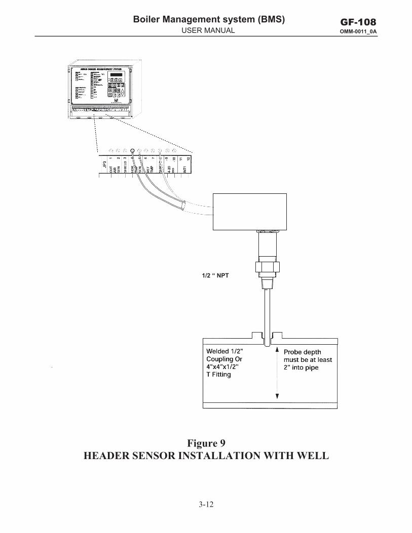
3.3.1 Header Sensor The header sensor to be used with the BMS is a sensor that requires a well as shown in Figure 9. When installing the sensor, use a 1/2 inch NPT tapped coupling or a 4 x 4 x 1/2 T fitting. Use heat-conductive grease when installing to aid in its response. The sensor probe must be inserted at least 2 inches into the flow of water for proper response. The header sensor must be installed between 2 and 10 feet downstream of the LAST boiler in the plant’s supply water header.
The header sensor is a thermistor type sensor. The Resistance vs. Temperature Charts for the sensor are provided in Appendix F. See Figure 9 for installation details.
Belden 9841 cable is recommended for header sensor wiring. There is no polarity to be observed. Connect the wires from the sensor to BMS terminals 4 and 5 on JP3. The ground for the shield is at BMS end of the link, not the header sensor. Connect the ground to JP3, terminal 8 (SHIELD). The header sensor can be installed up to 600 feet from the BMS.
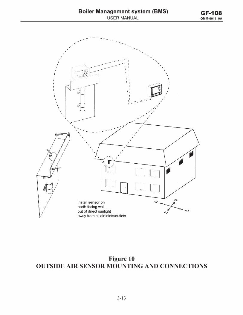
3.3.2 Outside Air Sensor The Outside Air Sensor, AERCO part no. GP-122662, must be mounted on the North side of the building, shielded from direct sunlight, and away from air intakes or outlets from the building. See Figure 10 for a typical installation. The sensor includes a plate for wall mounting. Belden 9841 cable, or equivalent, is recommended for sensor wiring. There is no polarity to be observed. Connect the sensor wires to BMS terminals 1 and 2 on JP3. Connect the shield to JP3, terminal 3 (SHIELD) at the BMS. The shield must not be grounded on the sensor end. The sensor can be mounted up to 600 feet from the BMS.
3-4
GF-108 OMM-0011_0A
Boiler Management system (BMS) g y ( )USER MANUAL
3-5
GF-108 OMM-0011_0A
Boiler Management system (BMS) g y ( )USER MANUAL
Figure 2 BMS MOUNTING
3-6
GF-108 OMM-0011_0A
Boiler Management system (BMS) g y ( )USER MANUAL
Figure 3 RECOMMENDED WIRE ROUTING LOCATIONS AT THE BMS
3-7
GF-108 OMM-0011_0A
Boiler Management system (BMS) g y ( )USER MANUAL
Figure 4 PWM COMMUNICATION OUTPUTS AT THE BMS
3-8
GF-108 OMM-0011_0A
Boiler Management system (BMS) g y ( )USER MANUAL
Figure 5 PULSE WIDTH MODULATION CONNECTIONS AT
KC SERIES BOILER WITH MODULAR CONTROL BOX
3-9
GF-108 OMM-0011_0A
Boiler Management system (BMS) g y ( )USER MANUAL
mA OUT
RS-485COMM.
+
-
+-
ANALOG IN
SENSOR COMMONOUTDOOR SENSOR IN REMOTE INTL'K IN
B.M.S. (PWM) IN
SHIELD
+-
+-
AUX SENSOR IN
NOT USED
EXHAUST SWITCH IN
DELAYED INTL'K IN
FAULT RELAY120 VAC, 5A, RES
AUX RELAY120 VAC, 5A, RES
G
NOT USED NOT USEDNCCOMNO
NCCOMNO
NOT USED
Remove sheetmetal cover toaccess I/O Box
PWM Connections
Figure 6 PULSE WIDTH MODULATION CONNECTIONS AT
KC SERIES BOILER WITH C-MORE CONTROL BOX
3-10
GF-108 OMM-0011_0A
Boiler Management system (BMS) g y ( )USER MANUAL
Figure 7 PULSE WIDTH MODULATION CONNECTIONS AT
BENCHMARK BOILER WITH MODULAR CONTROL BOX
3-11
GF-108 OMM-0011_0A
Boiler Management system (BMS) g y ( )USER MANUAL
Figure 8 PULSE WIDTH MODULATION CONNECTIONS AT
BENCHMARK BOILER WITH C-MORE CONTROL BOX
3-12
GF-108 OMM-0011_0A
Boiler Management system (BMS) g y ( )USER MANUAL
Figure 9 HEADER SENSOR INSTALLATION WITH WELL
1/2 “ NPT
3-13
GF-108 OMM-0011_0A
Boiler Management system (BMS) g y ( )USER MANUAL
Figure 10 OUTSIDE AIR SENSOR MOUNTING AND CONNECTIONS

GF-108 OMM-0011_0A
Boiler Management system (BMS) g y ( )USER MANUAL
4-1
GF-108 OMM-0011_0A
Boiler Management system (BMS) g y ( )USER MANUAL
Section 4 ______________________________
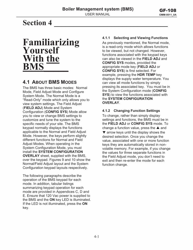
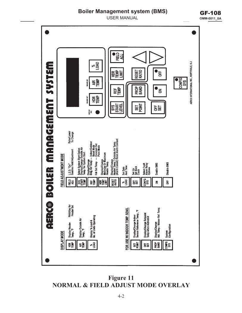
Familiarizing Yourself With the BMS_____ 4.1 ABOUT BMS MODES The BMS has three basic modes: Normal Mode, Field Adjust Mode and Configure System Mode. The Normal Mode is a “Read-Only” mode which only allows you to view system settings. The Field Adjust (FIELD ADJ) Mode and System Configuration (CONFIG SYS) Mode allow you to view or change BMS settings to customize and tune the system to the specific needs of your site. The BMS keypad normally displays the functions applicable to the Normal and Field Adjust Mode. However, the keys perform slightly different functions for Normal and Field Adjust Modes. When operating in the System Configuration Mode, you must install the SYSTEM CONFIGURATION OVERLAY sheet, supplied with the BMS, over the keypad. Figures 9 and 10 show the Normal/Field Adjust layout and the System Configuration keypad layouts respectively.
The following paragraphs describe the operation of the BMS keypad for each mode. In addition, tabular listings summarizing keypad operation for each mode are provided in Appendices C, D and E. Ensure that 120 Vac power is supplied tothe BMS and the ON key LED is illuminated.If the LED is not illuminated, press the ONkey.
4.1.1 Selecting and Viewing Functions As previously mentioned, the Normal mode, is a read-only mode which allows functions to be viewed, but not changed. However, functions associated with the keypad keys can also be viewed in the FIELD ADJ and CONFIG SYS modes, provided the appropriate mode key (FIELD ADJ or CONFIG SYS) is first selected. For example, pressing the HDR TEMP key displays the supply water temperature. You can view all mode functions by simply pressing its associated key. You must be in the System Configuration mode (CONFIG SYS) to view the functions associated with the SYSTEM CONFIGURATION OVERLAY.
4.1.2 Changing Function Settings To change, rather than simply display settings and functions, the BMS must be in the FIELD ADJ or CONFIG SYS mode. To change a function value, press the and
arrow keys until the display shows the desired selection. Once you change the value, associated with one or more function keys they are automatically stored in non-volatile memory. For example, if you change the values for three separate functions in the Field Adjust mode, you don’t need to exit and then re-enter the mode for each function change.
4-2
GF-108 OMM-0011_0A
Boiler Management system (BMS) g y ( )USER MANUAL O
Figure 11 NORMAL & FIELD ADJUST MODE OVERLAY
4-3
GF-108 OMM-0011_0A
Boiler Management system (BMS) g y ( )USER MANUAL O 00
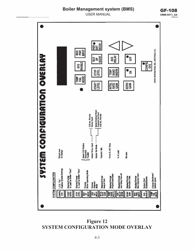
Figure 12 SYSTEM CONFIGURATION MODE OVERLAY
4-4
GF-108 OMM-0011_0A
Boiler Management system (BMS) g y ( )USER MANUAL
NOTE Sample Normal Mode displays with their Factory Default values are provided in Appendix C.
4.2 NORMAL MODE DISPLAYS AND FUNCTIONS When power is applied to the BMS, it is automatically placed in the Normal Mode. It allows you to view the settings currently stored in memory for BMS parameters. In addition, you can enter the Field Adjust or System Configuration Mode by pressing the FIELD ADJ or CONFIG SYS key. The functions provided by the keypad keys are described in the following paragraphs.
4.2.1 HDR TEMP Pressing and releasing this key displays the actual header sensor water temperature in °F. Pressing and holding this key displays the header setpoint temperature presently stored in memory.
4.2.2 AIR TEMP Pressing and releasing this key displays the actual outside air temperature. Pressing and holding this key displays the actual inside air temperature, only if an indoor air temperature sensor is installed. If an indoor air sensor is not installed, INDOOR AIR TEMP NOT CONNECTED will be displayed.
4.2.3 % LOADPressing and releasing this key displays the actual firing rate percentage (% Load) for the boiler plant. It also displays the number of boilers presently operating.
4.2.4 SYS START TEMP Pressing and holding this key displays the System Start Relay temperature setting in °F presently stored in memory. The system will start whenever the outside air temperatures drops below this setting.
4.2.5 REF TEMP Pressing and holding this key displays the Header Reference Temperature in °F presently stored in memory.
4.2.6 HDR TEMP LIMIT Pressing and holding this key displays the header high limit temperature setting (°F) stored in memory.
4.2.7 FIELD ADJ Pressing and releasing this key places the BMS in the Field Adjust Mode and lights the FIELD ADJ key LED. When this key is pressed, the display will read FLD ADJUSTMENT MAKE SELECTION. Refer to paragraph 4.3 for key functions when in this mode.
4.2.8 SET POINT Pressing and holding this key displays the indoor setpoint temperature (°F) stored in memory.
4.2.9 PROP BANDPressing this key displays the indoor air proportional bandwidth. This bandwidth is a variable used in an equation that solves for the proper offset of supply water temperature based on an indoor air temperature. Normally the display will read INDOOR PROP BAND 00.0°F/°F. See paragraph 4.3.9 for additional information.
4.2.10 OFFSETPressing and holding this key displays the Header Temperature Offset (°F) for the present time and day-of-the-week. See paragraph 4.3.10 for additional information on setting up an offset schedule.
4.2.11 RESET RATIO Pressing and holding this key will display the header reset ratio if a value is currently stored in memory. This function is only used in the Indoor/Outdoor Reset Mode. If this function is not set, or the Constant Setpoint or Remote (4-20 mA) mode is used, the display will show FUNCTION NOT VALID.
Also, ALARM CANCEL is printed directly above this key. Pressing and releasing this key will open the Alarm Relay contacts until the Alarm condition reappears.
4-5
GF-108 OMM-0011_0A
Boiler Management system (BMS) g y ( )USER MANUAL
4.2.12 and Arrow Keys The and arrow keys are not active in this mode, since no changes can be made to the displayed settings
4.2.13 ON and OFF Keys Pressing and releasing the ON or OFF key enables or disables the BMS. In addition, the corresponding key LED will light when the key is pressed.
4.2.14 CONFIG SYS Pressing and releasing this key places the BMS in the System Configuration Mode and lights the CONFIG SYS key LED. When this key is pressed, the display will read CONFIG. SYSTEM MAKE SELECTION. Refer to paragraph 4.4 for key functions when in this mode.
NOTE Sample Field Adjust Mode displays with their Factory Default values are provided in Appendix D.
4.3 FIELD ADJUST MODE DISPLAYS AND FUNCTIONS The Field Adjust Mode allows you to view or change settings currently stored in memory for BMS parameters. Many of the settings in this mode have been preset by AERCO to their Factory Defaults. However, you can reset many functions to suit the specific needs of your BMS installation. The following discussion refers to the functions of the keys.
The Field Adjust Mode is entered by simply pressing the FIELD ADJ key and verifying that the FIELD ADJ key LED lights.
4.3.1 HDR TEMP Pressing and holding this key displays the actual header sensor water temperature in °F. This is a “Read Only” display and cannot be changed.
4.3.2 AIR TEMP Pressing and holding this key displays the actual outside air temperature sensor
reading in °F. This is also a “Read Only” display and cannot be changed
4.3.3 % LOADThe % LOAD key has two separate and distinct functions in the Field Adjust Mode. Pressing and holding this key displays the actual firing rate (load) percentage and the number of boilers presently operating. Releasing the % LOAD key changes its function to Setting the Internal Clock as described in the following paragraph.
4.3.4 Setting the Internal Clock With The % LOAD Key Pressing and releasing the % LOAD key changes the first line of the display to SET TIME CLOCK. The second line of the display will show: MONTH, DATE, YEAR, DAY, HOURS, or MINS. Since these functions wrap around, it is strongly suggested that you repeatedly press the % LOAD key until the display shows MONTH: in the second line. This will make the following steps easier to follow:
NOTE When performing the following steps, use the and arrow keys to increment or decrement the displayed value. Pressing and holding the or key will change the displayed value at a rapid rate.
1. Press key until MONTH: is displayed. Setthe actual number of the month (1-12).
2. Press key again to display DATE:. Setthe actual day of the current month(1-31).
3. Press key again to display YEAR:. Setthe last 2 digits of the year.
4. Press key again to display DAY:. Set theday that you want to be the first day ofthe week. AERCO normally sets Sundayas DAY 1, however any day of the weekcan be set as DAY 1.
For example, if the actual DATE (day ofmonth) entered in step 2 is a Monday,and you want Monday to be the first day
4-6
GF-108 OMM-0011_0A
Boiler Management system (BMS) g y ( )USER MANUAL
of the week, set DAY: to 1. Conversely, if you want to retain Sunday as the first day of the week, set DAY: to 2 to indicate you are currently in the second day of the week.
5. Press key again to display HOURS:. Setthe hours using the 24-hour format (0 to23).
6. Press key again to display MINS:. Setthe minutes (0 to 59).
7. This completes the Internal Clocksettings.
4.3.5 SYS START TEMP When in the Field Adjust Mode, the SYS START TEMP key has two functions. First, It lets you select the outdoor temperature at which the system starts. Second, it lets you select the system start option (TEMP ONLY or TEMP AND LOAD).
For example, with the system start temperature set at 70°F (SYS. START RELAY 70°F), the system start relay will close and enable the boilers when the outside air temperature falls to 69°F (or lower).
To always enable the boilers, regardless of the system start temperature, or if an outside air temperature sensor is not used, see paragraph 4.4.2 in the System Configuration Mode section.
Pressing and releasing the SYS START TEMP key once displays the System Start Relay temperature. (AERCO presets System Start to an outside air temperature of 70°F).
Pressing and releasing this key a second time displays the System Start Option which can be set to either outside air temperature only (TEMP ONLY) or outside air temperature and load (TEMP AND LOAD). To change Start Option, press or key to toggle the setting.
If TEMP ONLY is chosen, the BMS will close the system start relay contacts when the outdoor air temperature drops below the
system start temperature setting, without regard to load.
The TEMP AND LOAD feature is used when the System Start Relay will control dampers. It keeps dampers closed until it is necessary to open them for combustion. This is designed to ensure that cold air is not always entering the boiler room.
If TEMP AND LOAD is chosen, two conditions are necessary for the system start relay contacts to close and enable the boilers. First, the firing rate (displayed as % LOAD) must be above 11%. Second the outdoor air temperature must be below the system start temperature. The system start relay contacts will open when the load percentage falls below 7%.
4.3.6 REF TEMP The REF TEMP key has two functions, depending on the operating mode used by the boilers connected to the BMS.
In the Indoor/Outdoor Reset Mode, pressing and releasing this key displays the Building Reference Temperature.
In the Constant Setpoint Mode, pressing this key displays the header supply water temperature setpoint (HEADER REF. TEMP).
To change the displayed Reference Temperature, press the or arrow key.
4.3.7 HDR TEMP LIMIT This key allows you to view or change the low and high temperature limits for the header supply water temperature.
In addition, when in the 4-to-20 mA Remote Setpoint Mode, it automatically scales the 4-to-20 mA signal. Accordingly, 4 mA will be equal to the header low limit setting and 20 mA will be equal to the header high limit setting.
Pressing and releasing this key once displays the header high limit temperature (HDR HIGH LIMIT).
4-7
GF-108 OMM-0011_0A
Boiler Management system (BMS) g y ( )USER MANUAL
Pressing and releasing this key a second time displays the header low limit temperature (HDR LOW LIMIT).
Pressing and releasing this key a third time displays the header offset temperature (HEADER OFFSET).
To change the displayed header high, low or offset temperature limits, press the or
arrow key.
4.3.8 FIELD ADJ The FIELD ADJ key LED should be lit to indicate that the BMS is already in the Field Adjust Mode. Pressing and releasing this key when already in the Field Adjust Mode will cause the BMS to exit the Field Adjust Mode and switch the BMS to the Normal (Read-Only) Mode.
4.3.9 SET POINT Pressing and releasing this key allows you to view or change the indoor setpoint temperature. This function is only used when an indoor air temperature sensor is connected to the BMS. If used, the input can be provided by a resistive type sensor, or a 4-to-20 mA input.
4.3.10 PROP BAND Pressing this key displays the indoor air proportional bandwidth. This bandwidth is a variable used in an equation that solves for the proper offset of supply water temperature based on an indoor air temperature. Normally, the display will read INDOOR PROP BAND 00.0°F/°F.
AERCO presets the proportional bandwidth to 00.00°F/°F. It should NOT be readjusted unless your system has an indoor air temperature sensor and is operating in the Indoor Setpoint mode. If the indoor temperature feature is not being used, PROP BAND MUST be set to 00.00°F/°F or the BMS will not run the boiler plant.
4.3.11 OFFSETThe OFFSET key is used to enable and set up an Offset Schedule for the header supply
temperature. The schedule can be set up for a 7-day period.
Pressing and releasing this key once will display OFFSET ENABLE followed by OFF or ON (Default is OFF). If an Offset Schedule will be used, toggle the display to ON using the or arrow key. See paragraph 4.3.12 for step-by-step procedures on how to set up an Offset Schedule.
IMPORTANT Prior to setting up a Reset Schedule, refer to the paragraph 4.3.4 to determine which Day of the Week has been set as Day 1. AERCO presets Day 1 of the week as Sunday. However, any day of the week can be specified as Day 1 by performing the steps outlined in paragraph 4.3.4.
4.3.12 Setting Up A Reset Schedule The basic steps for setting up a Reset Schedule consist of first selecting the temperature offset and then entering the start and stop times for which the offset will be in effect. Keep in mind that the BMS uses a 24-hour clock (00:00 to 23:59).
In the following example, for Day 1, we want to offset the setpoint temperature by -15°F starting at 12:30 am (00:30) and return it to the normal setpoint at 8:15 am (08:15). Proceed as follows:
1. Press OFFSET key once and toggle thedisplay to OFFSET ENABLE ON.
2. Press key a second time. OFFSETTEMP DAY 1 is displayed promptingentry of the offset temperature. Set theoffset temperature to -15 using the and arrow keys.
3. Press key a third time. OFFSET ONTIME DAY 1 0: 0 is displayedprompting Hours to be entered for thestart time. Set the Hours to zero(midnight) using the and arrowkeys.
4-8
GF-108 OMM-0011_0A
Boiler Management system (BMS) g y ( )USER MANUAL
4. Press key a fourth time. OFFSET ONTIME DAY 1: 0 0 is displayed,prompting Minutes to be entered for thestart time. Set the Minutes to 30 usingthe and arrow keys.
5. Press key a fifth time. OFFSET OFFTIME DAY 1 0: 0 is displayedprompting Hours to be entered for offtime. Since the BMS uses a 24-hourclock format, set the Hours to 8 using the
and arrow keys.
6. Press key a sixth time. OFFSET OFFTIME DAY 1: 8 0 is displayedprompting Minutes to be entered. Set theMinutes to 15 using the and arrowkeys.
7. This completes the steps for setting theOffset Temperature, and Start/StopTimes for Day 1.
For a 7-Day Schedule, the above steps would be repeated as needed. Offset Schedule entries stored in memory can be reviewed by repeatedly pressing the OFFSET key as needed.
4.3.13 RESET RATIO The Reset Ratio is only used in the Indoor/Outdoor Reset Mode of operation. This ratio the amount that the supply water temperature will rise for each degree drop in outside air temperature. A reset ratio of 2.0 means that the supply water temperature will increase 2°F for every 1°F decrease in outdoor air temperature. For example, if the building reference temperature is set at 70°F, when outside air temperature drops to 69°F, and the reset ratio is 1.8, the water supply temperature will increase to 71.8°F. AERCO presets the Reset Ratio to 1.2°F/°F. See Appendix B for Reset Ratio Charts.
Pressing and releasing this key will display the Header Reset Ratio (°F/°F) if a value is currently stored in memory. When operating in the Constant Setpoint or Remote (4-20 mA) mode, the display will show FUNCTION NOT VALID.
4.3.14 and Arrow Keys These keys are used to increment ( ) or decrement ( ) the displayed variable, or toggle the display through available options. When these keys are depressed and held the displayed value will increment or decrement at a rapid rate.
4.3.15 ON and OFF Keys Pressing and releasing the ON or OFF key enables or disables the BMS. In addition, the corresponding LED will light when the corresponding key is pressed.
4.3.16 CONFIG SYS When the BMS is in the Field Adjust Mode, this key has two functions. First, it allows you to select the types of faults which will cause an alarm. Second, it allows you to select how alarms are cleared.
Pressing and releasing the CONFIG SYS key once displays the FAULT ALARM RELAY status and allows you to select the types of faults which will cause an alarm. The choices are: ALL FAULTS, NO INTERLOCK, INTERLOCK 2 or INTERLOCK 1.
Selecting ALL FAULTS causes the BMS Fault Relay to close and generate an alarm when either Interlock 1 or Interlock 2 opens.
Selecting INTERLOCK 2 causes the Fault Relay to close and generate an alarm only when Interlock 2 opens. However, if INTERLOCK 1 opens, a fault message will be generated but the Fault Relay will not be closed.
Selecting INTERLOCK 1 causes the Fault Relay to close and generate an alarm only when Interlock 1 opens. However, if INTERLOCK 2 opens, a fault message will be generated but the Fault Relay will not be closed.
Selecting NO INTERLOCK causes the Fault Relay to remain open and not generate an alarm when either Interlock 1 or Interlock 2 opens. It should be noted
4-9
GF-108 OMM-0011_0A
Boiler Management system (BMS) g y ( )USER MANUAL
however that the BMS will always shut down the boilers when Interlock 1 or 2 opens, regardless of the selected Fault Relay option.
Select the desired option using the or arrow keys.
Pressing and releasing the CONFIG SYS key a second time displays FAULT ALARM CLEAR and allows you to select how faults are cleared. The available choices are MANUAL RESET or AUTOMATIC. Toggle to the desired option using the or arrow key.
Prior to placing the BMS in the System Configuration Mode, the FIELD ADJ key must be pressed to exit the Field Adjust Mode. Pressing and releasing the CONFIG SYS key places the BMS in the System Configuration Mode and lights the CONFIG SYS key LED. When this key is pressed, the display will read CONFIG. SYSTEM MAKE SELECTION. Refer to paragraph 4.4 for key functions when in this mode.
NOTE Sample System Configuration mode displays with their Factory Default values are provided in Appendix E.
4.4 SYSTEM CONFIGURATION MODE DISPLAYS AND FUNCTIONS The System Configuration Mode allows you to program and operate the BMS to effectively run and manage the performance of the boiler plant. In order to effectively use this mode, the SYSTEM CONFIGURATION OVERLAY provided with the BMS must be placed over the keypad for proper identification of key functions (Figure 12).
The System Configuration Mode is entered by simply pressing the CONFIG SYS key and verifying that the CONFIG SYS key LED lights.
The keys described in the following paragraphs allow you to view or change settings currently stored in memory. If the desired setting is not displayed for the selected BMS parameter, press the or arrow key to increase, decrease or toggle the displayed setting. All changes made will be stored in memory.
4.4.1 TEMP FAIL MODE Pressing and holding this key displays the actual header sensor water temperature in °F. This is a “Read Only” display and cannot be changed.
Pressing and releasing this key allows you to display and select a Temperature Failure Mode (TEMP FAIL MODE) of either SHUTDOWN or SWITCH INPUTS.
If SHUTDOWN is selected, regardless of the operating mode, the BMS will shut down the boiler plant whenever a temperature sensor fails or either interlock opens. If the BMS is operating in the 4-to-20-mA mode, the BMS will also shut down the boiler plant if the 4-to-20-mA signal drops below 3 mA. If any of these failures occur, the fault relay will close and the BMS will display the appropriate failure message.
If SWITCH INPUTS is selected, the BMS will automatically switch to Constant Setpoint mode if a sensor or remote input error occurs. Once the sensor or remote input error has been cleared, the BMS will automatically switch to the previous mode.
When selecting SWITCH INPUTS, the reference temperature for the Constant Setpoint mode must be preset. See Section 5 for programming steps.
Regardless of whether SHUTDOWN or SWITCH INPUTS is selected, the BMS will shut down and close the fault relay contacts if the header sensor circuit fails.
4-10
GF-108 OMM-0011_0A
Boiler Management system (BMS) g y ( )USER MANUAL
4.4.2 SYS ENABLE Pressing and releasing this key allows you to select the INTERLOCK 1 enable setting of START ENABLED or ALWAYS ENABLED.
The START ENABLED feature will not enable the boiler plant until the outside air temperature falls below the system start temperature. If the boiler plant begins to operate and Interlock 1 is open, the BMS will wait 30 seconds before stopping the boilers and displaying a fault message.
This feature is intended for use with auxiliary equipment having limit switches. For instance, dampers with proving end switches, can be triggered by the BMS system start relay or the boiler’s AUX relay as the boilers start. If the dampers do not open, the end switch wired to Interlock 1 will not make (close) and the BMS will shut down the boilers.
The ALWAYS ENABLED feature allows the boilers to run, regardless of the system start and outside air temperature settings. This feature is used when there is a loss of an outside air sensor or one is not installed. It will also function if an outside air temperature sensor is present. It should be noted that if either Interlock 1 or 2 opens, the BMS will shut down the boilers.
The system start relay will close only after the outside air temperature falls below the system start temperature, whether START ENABLED or ALWAYS ENABLED is selected. AERCO recommends that the system be equipped with a flow switch that is interlocked to the BMS. This is especially important if ALWAYS ENABLED is selected and the BMS is controlling the pumps based on outside air temperature, or the BMS is interfaced with an energy management system that is controlling the pumps.
4.4.3 MAX PWR INPUT This key is used to establish the maximum firing rate percentage for the boilers being controlled by the BMS. If desired, the maximum firing rate of the boilers can be
limited to values below 100%. This is useful if there are problems with gas supply pressure. For example, if gas pressure is too low, the boilers can be run at a lower firing rate temporarily until proper gas pressure can be restored.
Pressing the MAX PWR INPUT key displays the maximum allowable firing rate percentage for the boilers.
4.4.4 START LEVEL and STOP LEVEL Keys These keys allow you to set the energy levels (firing rate percentages) at which additional boilers are staged-in or staged-out of the system during Sequential or Combination mode operation. While the start level can be set at any percentage up to 100%, it is best to keep it below 60%. This allows the system to operate at optimum efficiency under low loads. The BMS is preset with 45% start and 18% stop levels, which generally provide the best performance.
When changing the start or stop levels, it is important to remember that load-balancing affects bumpless transfer. A sufficiently wide gap between the start and stop levels must be maintained to prevent cycling between units. For example, in a two-boiler system with a start level of 60% and a stop level of 30%, when the first boiler reaches 60%, the BMS will distribute the load between the two boilers, so that each will have a firing rate of 30%. However, since the stop level is 30%, the BMS will automatically shut down one boiler and allow the firing rate of the second boiler to increase to 60%. The BMS will then repeat this undesirable cycling. To avoid this, the start level could be set to 65%, leaving the stop level at 30%. When the BMS distributes the load after the first boiler reaches a 65% firing rate, the individual load would be 32.5%, sufficiently above the stop level. Conversely, the stop level could be changed to 25%, leaving the start level at 60%. In this case, when the BMS distributes the load, there will be 5% margin between this load (30%) and the stop level (25%).
4-11
GF-108 OMM-0011_0A
Boiler Management system (BMS) g y ( )USER MANUAL
Pressing the START LEVEL key displays firing rate percentage at which the boilers will start.
Pressing the STOP LEVEL key displays firing rate percentage at which the boilers will stop.
4.4.5 BLR OP MODE This key is used to select the Boiler Operating Mode. It allows you to make choices concerning the effective and efficient way to fire the boilers based on the building load. The mode choices include: Parallel, Sequential, or Combination Mode.
Pressing the BLR OP MODE key displays BOILER OP MODE followed by the currently selected mode (PARALLEL, SEQUENTIAL or COMBINATION). AERCO presets the mode to SEQUENTIAL. If necessary, use the and arrow keys to toggle between the 3 available modes. The following paragraphs describe the advantages of each mode selection.
4.4.5.1 Sequential Mode The Sequential Mode provides a greater turn-down ratio than Parallel Mode. This is because the turn-down ratio in Sequential Mode is equal to the number of boilers multiplied by 14 for KC Series boilers and by 15 for Benchmark boilers. In Parallel Mode, the turn-down ratio is fixed at 14:1 for KC Series boilers and 15:1 for Benchmark boilers, and does not consider the number of boilers in the plant.
In Sequential Mode, each boiler is started one at a time based on the load and start/stop levels programmed in the BMS. The BMS will start a single boiler when there is a load demand. Once the first boiler reaches the start level, a second boiler will be started and the load will be distributed evenly between the two boilers.
For instance, if a start level of 50% is chosen, when the first boiler reaches 50% a second boiler will start (after a 30 second delay), and the BMS will distribute the load
25% for each boiler. If the firing rate of both boilers reach the start level, a third boiler is started by the BMS (after a 30 second delay), and the load will be distributed across all three boilers. This sequence will continue base on load demand and the number of boilers connected to the BMS.
As the load drops off, the firing rates decrease. When all boilers reach the stop level, the first boiler turned on will be shut off by the BMS and its load will be evenly distributed to the remaining firing boilers. This off-sequencing continues until only one boiler is left firing. The last boiler will turn off when its stop level is reached.
4.4.5.2 Parallel Mode When operating in Parallel Mode, the boilers are simultaneously started by the BMS. The start and stop levels have no effect when in Parallel Mode. The turn-down ratio in Parallel Mode is fixed at 14:1 for KC 1000 Series boilers and 15:1 for Benchmark boilers, regardless of the number of boilers in the plant.
4.4.5.3 Combination Mode Combination mode is used only when the boiler plant will be used to satisfy both space heating and domestic hot water needs. This configuration, known as a Combination System, is used in conjunction with an AERCO Combination Control Panel (CCP). This system uses BMS-mode boilers dedicated to space heating and Combination boilers that are primarily used to satisfy the domestic hot water need. The domestic combination boilers are also available for the space heating load when the domestic hot water load is satisfied. This is accomplished using a motorized valve and storage tank equipped with a heat exchanger. For more information concerning the Combination System, see AERCO’s CCP-1 literature.
4-12
GF-108 OMM-0011_0A
Boiler Management system (BMS) g y ( )USER MANUAL
4.4.5.4 Designating the Number of Combination Boilers Up to 4 combination boilers can be connected to the BMS. However, when using the Combination Mode, it is necessary to tell the BMS how many combination boilers there are, and their size in millions of BTUs (MBTUs). This is accomplished as follows:
1. With the COMBINATION MODEselected, press the BLR OP MODE key.The display will read: COMBINATIONMODE X OF CCP BOILERS, (where Xis the number of Combination boilers).
2. Enter the number of Combination boilersconnected to the BMS using the and
arrow keys.
3. Press the BLR OP MODE key again.The display will read: COMBINATIONMODE X OF .5MBTU BLR.
4. Enter the number of .5MBTU boilers (ifany) connected to the BMS using the and arrow keys.
5. Press the BLR OP MODE key again.The display will read: COMBINATIONMODE X OF 1 MBTU BLR.
6. Enter the number of 1 MBTU boilers(KC1000 Series) connected to the BMSusing the and arrow keys.
7. Press the BLR OP MODE key again.The display will read: COMBINATIONMODE X OF 2 MBTU BLR.
8. Enter the number of 2 MBTU boilers(Benchmark Series) connected to theBMS using the and arrow keys.
9. This completes the entries required forCOMBINATION MODE operation.
IMPORTANT When connecting combination boilers to the BMS, it is important that you start at the BLR 8 terminals on Terminal Strip JP2 and work towards BLR 1.
4.4.6 HDR SET MODE This key has two functions. First, it is used to select the Indoor/Outdoor Reset, Constant Setpoint, or Remote 4-to-20-mA boiler mode operation. Second, it is used to select the type of indoor temperature sensor used with the BMS, if one is installed. The type of sensor can be either resistive (thermistor) or a constant voltage signal with current varying from 4 to 20 mA.
Pressing the HDR SET MODE key once selects the Header Set Mode function. If the desired mode is not displayed, toggle the display to the desired mode (IN/OUTDOOR RESET, REMOTE (4-20ma.) or CONSTANT SETTEMP) using the or arrow key.
Pressing the HDR SET MODE key a second time toggles the display to indicate the type of indoor temperature sensor which will be used with the BMS (INDOOR TEMP INP. THERMISTOR INPUT or 4-20 mA INPUT). If necessary, toggle the display using the or arrow key.
If the 4-to-20-mA boiler mode is selected and the Indoor Temperature Sensor feature is used, the Sensor input must be THERMISTOR (resistive) since the BMS has only one 4-to-20 mA input.
4.4.7 INTGL RATE GAIN TEMP BANDWIDTH and DERIV GAIN Keys These three keys provide PID (Proportional Integral Derivative) control functions which govern temperature control and response of the BMS to the boiler system. Since each system is different, these PID controls can tune the BMS to the characteristics of your specific installation. The factory defaults preset by AERCO work well for most applications. In instances when there is a large error between the setpoint and the actual supply water temperature, the BMS may appear to require PID tuning. However, It is best to observe BMS operation over a period of time prior to making any PID changes. Contact AERCO or an AERCO representative prior to making any PID setting changes.
4-13
GF-108 OMM-0011_0A
Boiler Management system (BMS) g y ( )USER MANUAL
The functions provided by the PID function keys are described in the following paragraphs.
4.4.7.1 TEMP BANDWIDTH Header Temperature Bandwidth (HDR TEMP B.W.) concerns the system’s response to the setpoint error. Setpoint error is the difference between the supply water temperature setpoint and the actual supply water temperature. A constant setpoint error will yield a constant and proportionate correction factor for the duration of the error. If there is a deviation from the constant error, the correction factor will be changed in proportion to the deviation. For instance, a temperature bandwidth of 50°F is chosen. The header temperature setpoint is 180°F and the actual incoming supply water temperature is 130°F. This is a 50° error and the following is true:
Temp. Error_____Prop Bandwidth
X 100 = Firing Rate in %
Therefore:
5050
X 100% = Firing Rate
1 X 100 = 100 % Firing Rate
With an error of 30° and a bandwidth of 50, the following would be true:
30/50 X 100 = .6 X 100 = 60% Firing Rate
4.4.7.2 INTGL RATE GAIN Integral gain responds to the setpoint error over a period of time. Integral references the proportional bandwidth error signal and sums itself with respect to the period of time that an error exists. Based on the example in the previous paragraph (4.4.7.1), if the integral is 0.15 repeats per minute and the firing rate is 60%, and a temperature error exists for 1 minute, then the following is true:
(0.15 reps/min.) x (60% firing rate) = 9% actual firing rate
60% firing rate +9% firing rate = 69% firing rate
If the error continues and is present for another minute, another 9% correction factor will be added:
69% firing rate +9% firing rate = 78% firing rate
If, after a load change, the supply water temperature stabilizes at a temperature above or below the setpoint, the integral gain should be increased. If, after a load change, the supply water temperature overshoots and oscillates excessively, integral gain should be reduced.
4.4.7.3 DERIV GAIN Derivative gain is a function of time. It senses and responds to the rate of change of the setpoint error. A slow rate of change will yield a small amount of derivative gain. Conversely, a fast rate of change will yield a large derivative gain. Too high a derivative gain setting will produce a large output for a short time. This can result in overshoot of the setpoint. Too low a derivative gain setting will have the opposite effect, producing a small output for a longer period, and may result in slow system response or the system undershooting the setpoint..
4.4.8 AUX RELAY This key is used to display or change the firing rate at which the Auxiliary Relay opens and closes. The Auxiliary Relay is typically used with AERCO’s Combination Control Panel (CCP) system or to start an auxiliary boiler for use under peak load conditions. If this boiler is of the non-condensing type, the OFF firing rate percentage must be high enough to prevent the boiler from operation in condensing mode.
Pressing the AUX RELAY key once displays the firing rate percentage at which the relay opens (AUX RELAY OPEN). The default value of 45% is acceptable for a CCP system. However, to run another non-condensing boiler, this percentage may need to be changed to approximately 70%.
4-14
GF-108 OMM-0011_0A
Boiler Management system (BMS) g y ( )USER MANUAL
The displayed percentage can be changed in 1% increments from 1 to 99%.
Pressing the AUX RELAY key again displays the firing rate percentage at which the relay closes (AUX RELAY CLOSE). Two options are available for this function, 100% FIRING RATE, or 100% AND OFF. Pressing the or arrow key will toggle the display. to 100% FIRE RATE which is the only other available setting. If the 100%FIRING RATE (default) is selected, the Auxiliary Relay contacts close when the BMS indicates that all boilers are at a 100% firing rate. If 100% AND OFF is selected, the Auxiliary contacts close when the BMS indicates 100%, or when the BMSdetermines that all boilers are off. The off-state is when each boiler has either faulted, or someone has pressed the off button on the boilers. This function allows a boiler that is wired to the Auxiliary Relay contacts to fire when all of the other boilers have faulted or have been turned off.
When in Combination Control Panel (CCP) mode, care must be taken to ensure that the AUX RELAY OPEN percentage is set so that the system does not oscillate turning boilers on and off. A maximum open percentage of 45% is recommended for
Combination Control mode. If using the AUX contacts to fire an auxiliary boiler, the recommended open percentage is 70%.
4.4.9 and Arrow Keys These keys are used to increment ( ) or decrement ( ) the displayed variable, or toggle the display through available options. Pressing and holding these keys will increment or decrement the displayed value at a rapid rate.
4.4.10 ON and OFF Keys Pressing and releasing the ON or OFF key enables or disables the BMS. In addition, the corresponding LED will light when the corresponding key is pressed.
4.4.11 CONFIG SYS When the CONFIG SYS key LED is lit, pressing this key will exit the System Configuration Mode and place the BMS in the Normal Mode. When this occurs, the display will show HEADER TEMP (°F) which is the default Normal Mode display. See paragraph 4.2 for key functions in Normal Mode.
5-1
GF-108 OMM-0011_0A
Boiler Management system (BMS) g y ( )USER MANUAL
Section 5 ______________________________
Programming the BMS Mode of Operation__ Prior to programming, the BMS must be mounted and all required wiring completed. In addition, all connections should be checked for accuracy. The BMS is now ready to be programmed for the desired mode of operation of the boiler plant. The steps for programming will vary somewhat, depending on which of the three operating modes is selected
5.1 INDOOR/OUTDOOR RESET MODE The Indoor/Outdoor Reset mode is based on outside air temperature. The header supply water temperature will vary up or down in accordance with outside air temperature. This mode requires that, as a minimum, a System Start Temperature (SYS.START RELAY), Building Reference Temperature (BLDG REF. TEMP) and Reset Ratio be programmed into the BMS. This data is based on the degree days for your geographic area. An outdoor air sensor MUST be installed when operating in this mode (refer to paragraph 3.3.2).
5.1.1 Selecting Indoor/Outdoor Reset Mode To select Indoor/Outdoor Reset mode, perform the following steps:
1. Press the CONFIG SYS key to enter theSystem Configuration mode. TheCONFIG SYS key LED will illuminate.
2. Place SYSTEM CONFIGURATIONOVERLAY on the BMS front panel.
3. Press the HDR SET MODE key once.HEADER SET MODE is displayed withthe present mode selection.
4. While observing the display, toggle theHDR SET MODE using the or keyto IN/OUTDOOR RESET.
5.1.2 Entering System Start Temperature The system start temperature is the outside temperature at which the boiler plant begins to operate. AERCO presets the system start temperature at 70°F. However, temper-atures from 32 to 100°F can be selected using the and arrow keys on the keypad. Proceed as follows to enter the system start temperature::
1. Press FIELD ADJ mode key. Verify thatthe FIELD ADJ key LED illuminates.
2. Press the SYS START TEMP key.
3. Using the and arrow keys, selectthe desired Start Temperature for theboiler plant.
5.1.3 Determining the Reset Schedule There are two possible variables that must be considered when determining reset schedule - reset ratio and building reference temperature. There are two methods for determining reset ratio. The first uses the charts from Appendix B. This method is suitable for most installations. However, if a special reset schedule is desired for reheat or other purposes, the calculation method must be used. In this method, both reset ratio and building reference temperature must be calculated. See Appendix B for further instructions concerning both of these methods.
5-2
GF-108 OMM-0011_0A
Boiler Management system (BMS) g y ( )USER MANUAL
5.1.4 Entering the Building Reference Temperature To enter the Building Reference Temperature, perform the following steps:
1. Enter Field Adjust mode by pressing theFIELD ADJ key. Verify that the key LEDilluminates.
2. Press the REF TEMP key. The displaywill show the present BLDG REF. TEMP.
3. Using the and arrow keys, selectthe desired Building ReferenceTemperature.
5.1.5 Entering the Reset Ratio To enter the Reset Ratio, proceed as follows:
1. Ensure that the BMS is in the FieldAdjust mode.
2. Press the RESET RATIO key. Thedisplay will show RESET RATIO1.2°F/°F which is the default setting.
3. Using the and arrow keys, selectthe desired Reset Ratio.
4. Initialize the system as described inparagraph 5.5.
5.2 SETUP FOR 4-TO-20-MA REMOTE SETPOINT MODE In order to set up the BMS to operate in this mode, a 4-to-20 mA communications line from an Energy Management System with a floating ground and a BMS header sensor, are required. This mode may be used with or without an outdoor air temperature sensor installed. Entries in this mode are required for the Header Set Mode, Boiler Operating Mode and Building Reference Temperature.
5.2.1 Entering Header Set and Boiler Operating Modes These selections are made with the BMS in the System Configuration mode. Proceed as follows:
1. Press the CONFIG SYS key to enter theSystem Configuration mode. TheCONFIG SYS key LED will illuminate.
2. Place SYSTEM CONFIGURATIONOVERLAY on the BMS front panel.
3. Press the HDR SET MODE key once.HEADER SET MODE is displayed withthe present mode selection.
4. While observing the display, toggle theHDR SET MODE to REMOTE (4-20ma.)using the or arrow key.
5. Press the BLR OP MODE key. BOILEROP MODE is displayed with the presentlystored mode selection.
6. Select either the PARALLEL orSEQUENTIAL boiler mode using the or arrow key.
7. Press the CONFIG SYS key to exit theSystem Configuration mode. TheCONFIG SYS LED will go off.
8. Remove the SYSTEM CONFIG-URATION overlay from the BMS frontpanel.
5.2.2 Entering Building Reference Temperature The Building Reference Temperature is entered as follows:
1. Enter Field Adjust mode by pressing theFIELD ADJ key. Verify that the key LEDilluminates.
2. Press the REF TEMP key. The displaywill show the present BLDG REF. TEMP.
3. Using the and arrow keys, selectthe desired Building ReferenceTemperature.
4. Initialize the BMS using the proceduresin paragraph 5.5.
5-3
GF-108 OMM-0011_0A
Boiler Management system (BMS) g y ( )USER MANUAL
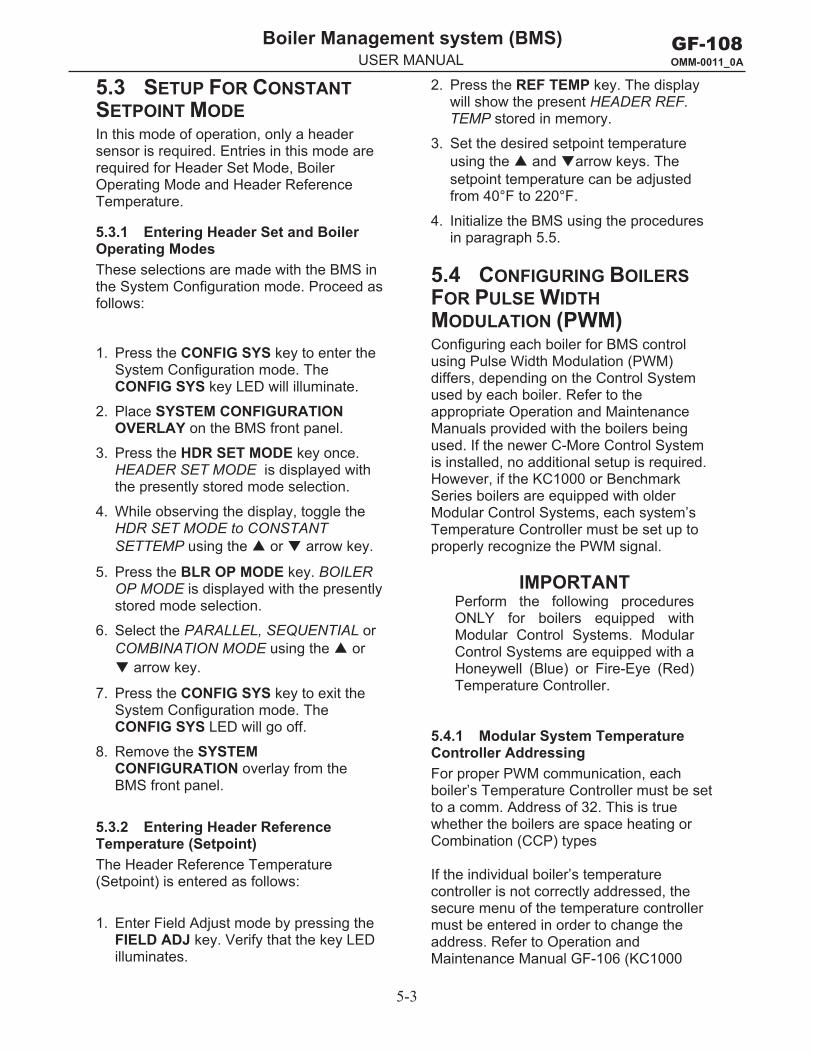
5.3 SETUP FOR CONSTANT SETPOINT MODE In this mode of operation, only a header sensor is required. Entries in this mode are required for Header Set Mode, Boiler Operating Mode and Header Reference Temperature.
5.3.1 Entering Header Set and Boiler Operating Modes These selections are made with the BMS in the System Configuration mode. Proceed as follows:
1. Press the CONFIG SYS key to enter theSystem Configuration mode. TheCONFIG SYS key LED will illuminate.
2. Place SYSTEM CONFIGURATIONOVERLAY on the BMS front panel.
3. Press the HDR SET MODE key once.HEADER SET MODE is displayed withthe presently stored mode selection.
4. While observing the display, toggle theHDR SET MODE to CONSTANTSETTEMP using the or arrow key.
5. Press the BLR OP MODE key. BOILEROP MODE is displayed with the presentlystored mode selection.
6. Select the PARALLEL, SEQUENTIAL orCOMBINATION MODE using the or
arrow key.
7. Press the CONFIG SYS key to exit theSystem Configuration mode. TheCONFIG SYS LED will go off.
8. Remove the SYSTEMCONFIGURATION overlay from theBMS front panel.
5.3.2 Entering Header Reference Temperature (Setpoint) The Header Reference Temperature (Setpoint) is entered as follows:
1. Enter Field Adjust mode by pressing theFIELD ADJ key. Verify that the key LEDilluminates.
2. Press the REF TEMP key. The displaywill show the present HEADER REF.TEMP stored in memory.
3. Set the desired setpoint temperatureusing the and arrow keys. Thesetpoint temperature can be adjustedfrom 40°F to 220°F.
4. Initialize the BMS using the proceduresin paragraph 5.5.
5.4 CONFIGURING BOILERS FOR PULSE WIDTH MODULATION (PWM) Configuring each boiler for BMS control using Pulse Width Modulation (PWM) differs, depending on the Control System used by each boiler. Refer to the appropriate Operation and Maintenance Manuals provided with the boilers being used. If the newer C-More Control System is installed, no additional setup is required. However, if the KC1000 or Benchmark Series boilers are equipped with older Modular Control Systems, each system’s Temperature Controller must be set up to properly recognize the PWM signal.
IMPORTANT Perform the following procedures ONLY for boilers equipped with Modular Control Systems. Modular Control Systems are equipped with a Honeywell (Blue) or Fire-Eye (Red) Temperature Controller.
5.4.1 Modular System Temperature Controller Addressing For proper PWM communication, each boiler’s Temperature Controller must be set to a comm. Address of 32. This is true whether the boilers are space heating or Combination (CCP) types
If the individual boiler’s temperature controller is not correctly addressed, the secure menu of the temperature controller must be entered in order to change the address. Refer to Operation and Maintenance Manual GF-106 (KC1000
5-4
GF-108 OMM-0011_0A
Boiler Management system (BMS) g y ( )USER MANUAL
Boiler) or GF-107 (Benchmark Boiler) for detailed procedures.
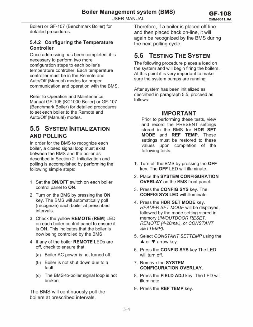
5.4.2 Configuring the Temperature Controller Once addressing has been completed, it is necessary to perform two more configuration steps to each boiler’s temperature controller. Each temperature controller must be in the Remote and Auto/Off (Manual) modes for proper communication and operation with the BMS.
Refer to Operation and Maintenance Manual GF-106 (KC1000 Boiler) or GF-107 (Benchmark Boiler) for detailed procedures to set each boiler to the Remote and Auto/Off (Manual) modes.
5.5 SYSTEM INITIALIZATIONAND POLLING In order for the BMS to recognize each boiler, a closed signal loop must exist between the BMS and the boiler as described in Section 2. Initialization and polling is accomplished by performing the following simple steps:
1. Set the ON/OFF switch on each boilercontrol panel to ON.
2. Turn on the BMS by pressing the ONkey. The BMS will automatically poll(recognize) each boiler at prescribedintervals.
3. Check the yellow REMOTE (REM) LEDon each boiler control panel to ensure itis ON. This indicates that the boiler isnow being controlled by the BMS.
4. If any of the boiler REMOTE LEDs areoff, check to ensure that:
(a) Boiler AC power is not turned off.
(b) Boiler is not shut down due to afault.
(c) The BMS-to-boiler signal loop is notbroken.
The BMS will continuously poll the boilers at prescribed intervals.
Therefore, if a boiler is placed off-line and then placed back on-line, it will again be recognized by the BMS during the next polling cycle.
5.6 TESTING THE SYSTEM The following procedure places a load on the system and will begin firing the boilers. At this point it is very important to make sure the system pumps are running.
After system has been initialized as described in paragraph 5.5, proceed as follows:
IMPORTANT Prior to performing these tests, view and record the PRESENT settings stored in the BMS for HDR SET MODE and REF TEMP. These settings must be restored to these values upon completion of the following tests.
1. Turn off the BMS by pressing the OFFkey. The OFF LED will illuminate..
2. Place the SYSTEM CONFIGURATIONOVERLAY on the BMS front panel.
3. Press the CONFIG SYS key. TheCONFIG SYS LED will illuminate.
4. Press the HDR SET MODE key.HEADER SET MODE will be displayed,followed by the mode setting stored inmemory (IN/OUTDOOR RESET,REMOTE (4-20ma.), or CONSTANTSETTEMP).
5. Select CONSTANT SETTEMP using the or arrow key.
6. Press the CONFIG SYS key The LEDwill turn off.
7. Remove the SYSTEMCONFIGURATION OVERLAY.
8. Press the FIELD ADJ key. The LED willilluminate.
9. Press the REF TEMP key.
5-5
GF-108 OMM-0011_0A
Boiler Management system (BMS) g y ( )USER MANUAL
10. Set the HEADER REF. TEMP (setpoint)to 220°F using the and arrowkeys.
11. Press the FIELD ADJ key. The LED willturn off.
12. Press the %LOAD key and monitor thedisplay for the firing rate (PERCENTOF LOAD) an the number of boilersfiring (Units).
13. When all boilers have reached at leasta 55% firing rate, any boilers that havenot started have not been identified bythe BMS.
Remember that in the Sequential orCombination modes, the BMS turns
boilers on in 30-second intervals. Therefore, in a 6-boiler plant, with five boilers operating at 55% capacity a boiler that has not started after 3 minutes, has not been recognized. In parallel mode, all boilers will start at the same time.
14. This completes the System Test.Return the HDR SET MODE and REFTEMP settings to their previouslystored values.
If the System Test is not completed successfully, contact AERCO at (201) 768-2400.

GF-108 OMM-0011_0A
Boiler Management system (BMS) g y ( )USER MANUAL

A-1
GF-108 OMM-0011_0A
Boiler Management system (BMS) g y ( )USER MANUAL
Appendix A ____________________________ SPECIFICATIONS
INPUTS
POWER
Input voltage 112 VAC, 60Hz, 1 phase, ± 10%, fused at 1 A
OUTSIDE AIR SENSOR (NTC thermistor)
Acceptable types AERCO GP-1 22662 (sensor only) GM-122781 (includes sensor & mounting plate)
Range -60° F to +80°F
Short sensor protection Invoked at +200°F
HEADER SENSOR (NTC thermistor)
Acceptable types AERCO GP-1 22757 (Sensor only) or AERCO GP-1 22790 (sensor and well) or GP-1 23822 (direct-immersion sensor for use without a well)
Range 40°F to +220°F
Short sensor protection Invoked at +300°F
REFERENCE temperature Sensor (NTC thermistor)
Acceptable types AERCO GP-122882 (sensor only)
Range 40°F to 160°F
Short sensor protection Invoked at 300°F
A-2
GF-108 OMM-0011_0A
Boiler Management system (BMS) g y ( )USER MANUAL
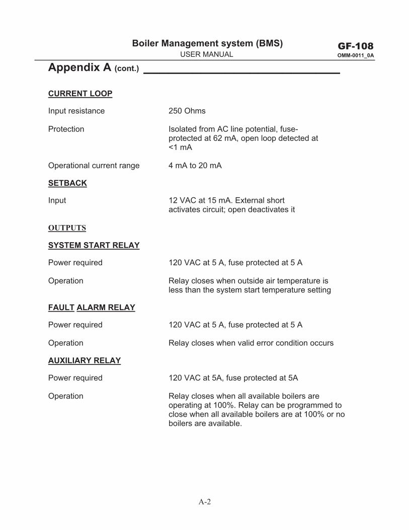
Appendix A (cont.) ________________________ CURRENT LOOP
Input resistance 250 Ohms
Protection Isolated from AC line potential, fuse- protected at 62 mA, open loop detected at
<1 mA
Operational current range 4 mA to 20 mA
SETBACK
Input 12 VAC at 15 mA. External short activates circuit; open deactivates it
OUTPUTS
SYSTEM START RELAY
Power required 120 VAC at 5 A, fuse protected at 5 A
Operation Relay closes when outside air temperature is less than the system start temperature setting
FAULT ALARM RELAY
Power required 120 VAC at 5 A, fuse protected at 5 A
Operation Relay closes when valid error condition occurs
AUXILIARY RELAY
Power required 120 VAC at 5A, fuse protected at 5A
Operation Relay closes when all available boilers are operating at 100%. Relay can be programmed to close when all available boilers are at 100% or no boilers are available.
A-3
GF-108 OMM-0011_0A
Boiler Management system (BMS) g y ( )USER MANUAL
Appendix A (cont.) ________________________
BOILER DRIVE
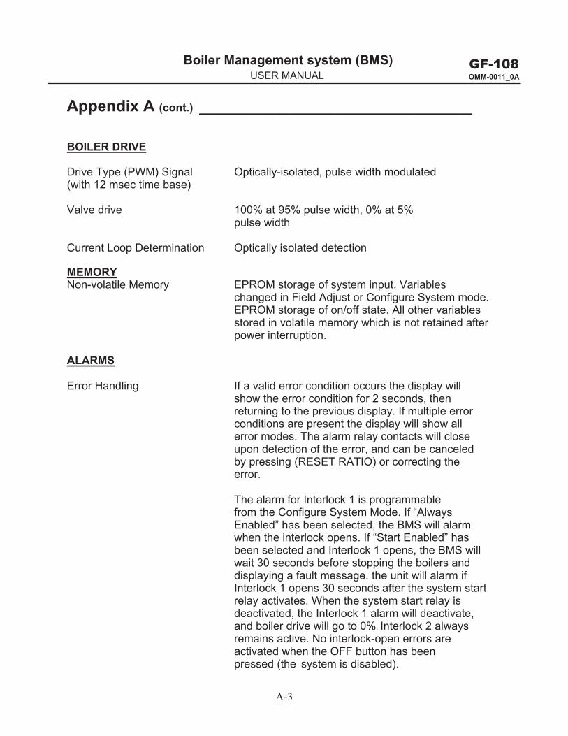
Drive Type (PWM) Signal Optically-isolated, pulse width modulated (with 12 msec time base)
Valve drive 100% at 95% pulse width, 0% at 5% pulse width
Current Loop Determination Optically isolated detection
Non-volatile Memory EPROM storage of system input. Variables changed in Field Adjust or Configure System mode. EPROM storage of on/off state. All other variables stored in volatile memory which is not retained after power interruption.
MEMORY
ALARMS
Error Handling If a valid error condition occurs the display will show the error condition for 2 seconds, then returning to the previous display. If multiple error conditions are present the display will show all error modes. The alarm relay contacts will close upon detection of the error, and can be canceled by pressing (RESET RATIO) or correcting the error.
The alarm for Interlock 1 is programmable from the Configure System Mode. If “Always Enabled” has been selected, the BMS will alarm when the interlock opens. If “Start Enabled” has been selected and Interlock 1 opens, the BMS will wait 30 seconds before stopping the boilers and displaying a fault message. the unit will alarm if Interlock 1 opens 30 seconds after the system start relay activates. When the system start relay is deactivated, the Interlock 1 alarm will deactivate, and boiler drive will go to 0%. Interlock 2 always remains active. No interlock-open errors are activated when the OFF button has been pressed (the system is disabled).
A-4
GF-108 OMM-0011_0A
Boiler Management system (BMS) g y ( )USER MANUAL
Appendix A (cont.) ________________________
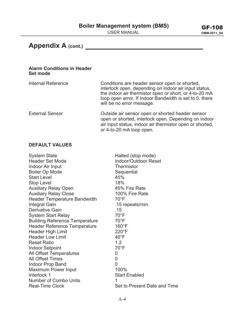
Alarm Conditions in Header Set mode
Internal Reference Conditions are header sensor open or shorted, interlock open, depending on indoor air input status, the indoor air thermistor open or short, or 4-to-20 mA loop open error. If Indoor Bandwidth is set to 0, there will be no error message.
External Sensor Outside air sensor open or shorted header sensor open or shorted, interlock open. Depending on indoor air input status, indoor air thermistor open or shorted, or 4-to-20 mA loop open.
DEFAULT VALUES
System State Halted (stop mode) Header Set Mode Indoor/Outdoor Reset Indoor Air Input Thermistor Boiler Op Mode Sequential Start Level 45%Stop Level 18%Auxiliary Relay Open 45% Fire Rate Auxiliary Relay Close 100% Fire Rate Header Temperature Bandwidth 70°F Integral Gain .15 repeats/min. Derivative Gain .15 System Start Relay 70°F Building Reference Temperature 70°F Header Reference Temperature 160°F Header High Limit 220°F Header Low Limit 40°F Reset Ratio 1.2 Indoor Setpoint 70°F All Offset Temperatures 0 All Offset Times 0 Indoor Prop Band 0 Maximum Power Input 100% Interlock 1 Start Enabled Number of Combo Units 1 Real-Time Clock Set to Present Date and Time
B-1
GF-108 OMM-0011_0A
Boiler Management system (BMS) g y ( )USER MANUAL
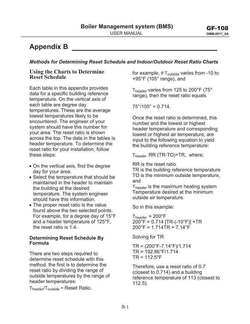
Appendix B _____________________________Methods for Determining Reset Schedule and Indoor/Outdoor Reset Ratio Charts
Using the Charts to Determine Reset Schedule
Each table in this appendix provides data for a specific building reference temperature. On the vertical axis of each table are degree day temperatures. These are the average lowest temperatures likely to be encountered. The engineer of your system should have this number for your area. The reset ratio is shown across the top. The data in the tables is header temperature. To determine the reset ratio for your installation, follow these steps:
On the vertical axis, find the degree day for your area. Select the temperature that should be maintained in the header to maintain the building at the desired temperature. The system engineer should have this information. The proper reset ratio is the value found above the two selected points. For example, for a degree day of 15°F and a header temperature of 125°F, the reset ratio is 1.4.
Determining Reset Schedule By Formula
There are two steps required to determine reset schedule with this method. the first is to determine the reset ratio by dividing the range of outside temperatures by the range of header temperatures: Theader/Toutside = Reset Ratio.
for example, If Toutside varies from -10 to +95°F (105° range), and
Theader varies from 125 to 200°F (75° range), then the reset ratio equals
75°/105° = 0.714.
Once the reset ratio is determined, this number and the lowest or highest header temperature and corresponding lowest or highest air temperature, are input to the following equation to yield the building reference temperature:
Theader - RR (TR-TO)+TR, where:
RR is the reset ratio TR is the building reference temperature TO is the minimum outside temperature, and Theader is the maximum heating system Temperature desired at the minimum outside air temperature.
So in this example:
Theader = 200°F 200°F = 0.714 [TR-(-10°F)] +TR 200°F = 1.714TR + 7.14°F
Solving for TR:
TR = (200°F-7.14°F)/1.714 TR = 192.86°F/1.714 TR = 112.5°F
Therefore, use a reset ratio of 0.7 (closest to 0.714) and a building reference temperature of 113 (closest to 112.5).
B-2
GF-108 OMM-0011_0A
Boiler Management system (BMS) g y ( )USER MANUAL
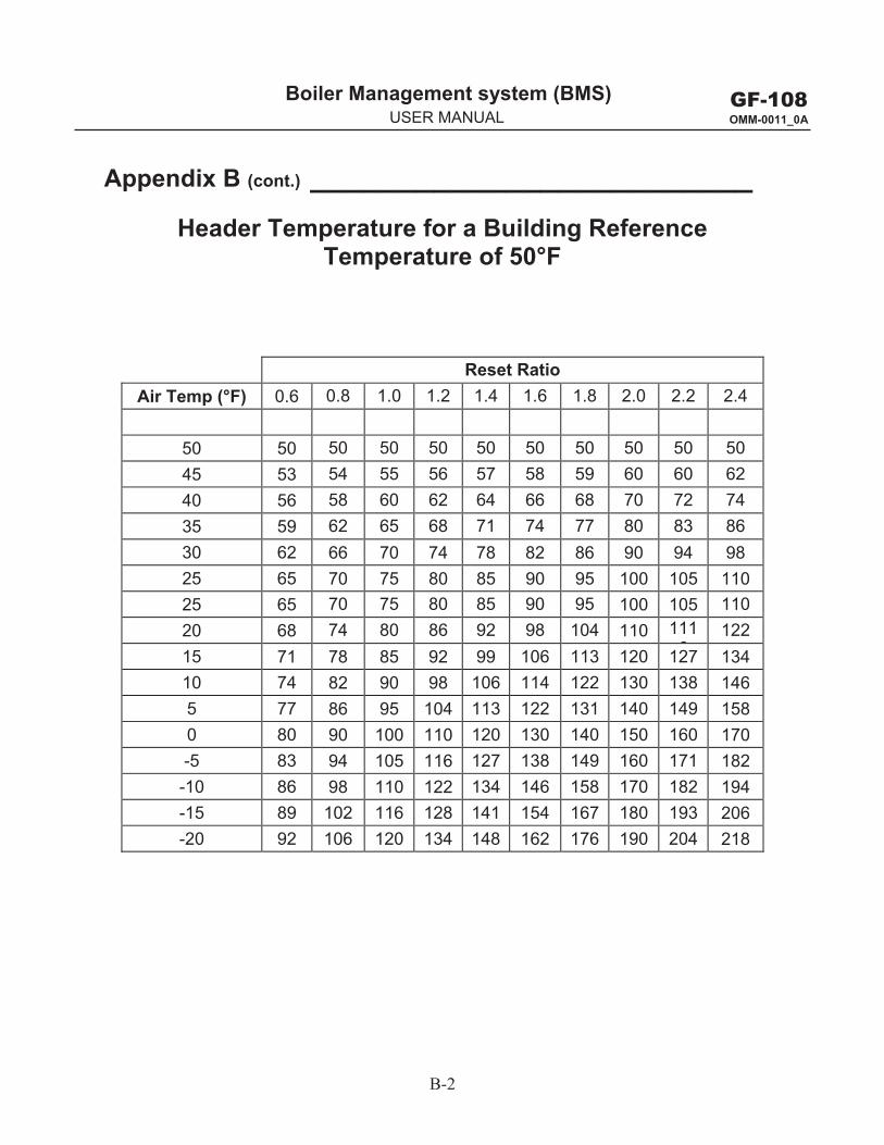
Appendix B (cont.) _________________________ Header Temperature for a Building Reference
Temperature of 50°F
Reset Ratio Air Temp (°F) 0.6 0.8 1.0 1.2 1.4 1.6 1.8 2.0 2.2 2.4
50 50 50 50 50 50 50 50 50 50 50 45 53 54 55 56 57 58 59 60 60 62 40 56 58 60 62 64 66 68 70 72 74 35 59 62 65 68 71 74 77 80 83 86 30 62 66 70 74 78 82 86 90 94 98 25 65 70 75 80 85 90 95 100 105 110 25 65 70 75 80 85 90 95 100 105 110 20 68 74 80 86 92 98 104 110 111
6122
15 71 78 85 92 99 106 113 120 127 134 10 74 82 90 98 106 114 122 130 138 146 5 77 86 95 104 113 122 131 140 149 158 0 80 90 100 110 120 130 140 150 160 170 -5 83 94 105 116 127 138 149 160 171 182 -10 86 98 110 122 134 146 158 170 182 194 -15 89 102 116 128 141 154 167 180 193 206 -20 92 106 120 134 148 162 176 190 204 218
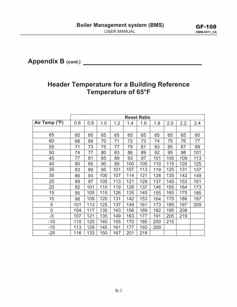
B-3
GF-108 OMM-0011_0A
Boiler Management system (BMS) g y ( )USER MANUAL
Appendix B (cont.) _________________________
Header Temperature for a Building Reference Temperature of 65°F
Reset Ratio Air Temp (0F) 0.6 0.8 1.0 1.2 1.4 1.6 1.8 2.0 2.2 2.4
65 65 65 65 65 65 65 65 65 65 65 60 68 69 70 71 72 73 74 75 76 77 55 71 73 75 77 79 81 83 85 87 89 50 74 77 80 83 86 89 92 95 98 101 45 77 81 85 89 93 97 101 105 109 113 40 80 85 90 95 100 105 110 115 120 12535 83 89 95 101 107 113 119 125 131 137 30 86 93 100 107 114 121 128 135 142 149 25 89 97 105 113 121 129 137 145 153 161 20 92 101 110 119 128 137 146 155 164 173 15 95 105 115 126 135 145 155 165 175 185 10 98 109 120 131 142 153 164 175 186 197 5 101 113 125 137 149 161 173 185 197 209 0 104 117 130 143 156 169 182 195 208 -5 107 121 135 149 163 177 191 205 219 -10 110 125 140 155 170 185 200 215 -15 113 129 145 161 177 193 209 -20 116 133 150 167 201 218
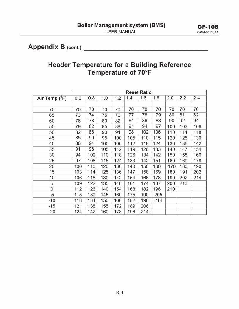
B-4
GF-108 OMM-0011_0A
Boiler Management system (BMS) g y ( )USER MANUAL
Appendix B (cont.) __________________________
Header Temperature for a Building Reference Temperature of 70°F
Reset Ratio Air Temp (0F) 0.6 0.8 1.0 1.2 1.4 1.6 1.8 2.0 2.2 2.4
70 70 70 70 70 70 70 70 70 70 70 65 73 74 75 76 77 78 79 80 81 82 60 76 78 80 82 64 86 88 90 92 94 55 79 82 85 88 91 94 97 100 103 106 50 82 86 90 94 98 102 106 110 114 118 45 85 90 95 100 105 110 115 120 125 130 40 88 94 100 106 112 118 124 130 136 142 35 91 98 105 112 119 126 133 140 147 154 30 94 102 110 118 126 134 142 150 158 166 25 97 106 115 124 133 142 151 160 169 178 20 100 110 120 130 140 150 160 170 180 190 15 103 114 125 136 147 158 169 180 191 202 10 106 118 130 142 154 166 178 190 202 214 5 109 122 135 148 161 174 187 200 213 0 112 126 140 154 168 182 196 210 -5 115 130 145 160 175 190 205 -10 118 134 150 166 182 198 214 -15 121 138 155 172 189 206 -20 124 142 160 178 196 214
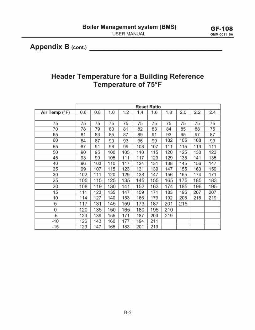
B-5
GF-108 OMM-0011_0A
Boiler Management system (BMS) g y ( )USER MANUAL
Appendix B (cont.) __________________________
Header Temperature for a Building Reference Temperature of 75°F
Reset Ratio Air Temp (°F) 0.6 0.8 1.0 1.2 1.4 1.6 1.8 2.0 2.2 2.4
75 75 75 75 75 75 75 75 75 75 75 70 78 79 80 81 82 83 84 85 88 75 65 81 83 85 87 89 91 93 95 97 8760 84 87 90 93 96 99 102 105 108 99 55 87 91 96 99 103 107 111 115 119 11150 90 95 100 105 110 115 120 125 130 12345 93 99 105 111 117 123 129 135 141 13540 96 103 110 117 124 131 138 145 156 14735 99 107 115 123 131 139 147 155 163 15930 102 111 120 129 138 147 156 165 174 171 25 105 115 125 135 145 155 165 175 185 183 20 108 119 130 141 152 163 174 185 196 195 15 111 123 135 147 159 171 183 195 207 207 10 114 127 140 153 166 179 192 205 218 219 5 117 131 145 159 173 187 201 215 0 120 135 150 165 180 195 210 -5 123 139 155 171 187 203 219
-10 126 143 160 177 194 211 -15 129 147 165 183 201 219
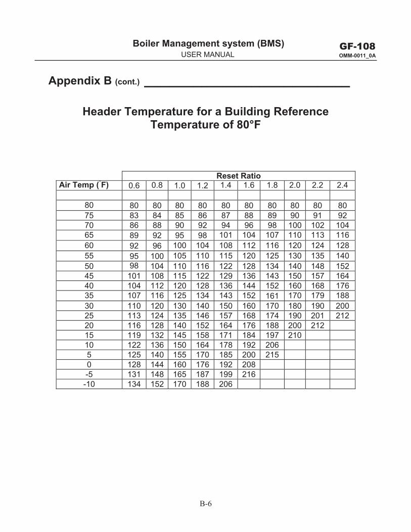
B-6
GF-108 OMM-0011_0A
Boiler Management system (BMS) g y ( )USER MANUAL
Appendix B (cont.) _________________________
Header Temperature for a Building Reference Temperature of 80°F
Reset Ratio Air Temp (°F) 0.6 0.8 1.0 1.2 1.4 1.6 1.8 2.0 2.2 2.4
80 80 80 80 80 80 80 80 80 80 80 75 83 84 85 86 87 88 89 90 91 9270 86 88 90 92 94 96 98 100 102 10465 89 92 95 98 101 104 107 110 113 116 60 92 96 100 104 108 112 116 120 124 128 55 95 100 105 110 115 120 125 130 135 140 50 98 104 110 116 122 128 134 140 148 152 45 101 108 115 122 129 136 143 150 157 164 40 104 112 120 128 136 144 152 160 168 176 35 107 116 125 134 143 152 161 170 179 188 30 110 120 130 140 150 160 170 180 190 200 25 113 124 135 146 157 168 174 190 201 212 20 116 128 140 152 164 176 188 200 212 15 119 132 145 158 171 184 197 210 10 122 136 150 164 178 192 206 5 125 140 155 170 185 200 215 0 128 144 160 176 192 208-5 131 148 165 187 199 216-10 134 152 170 188 206
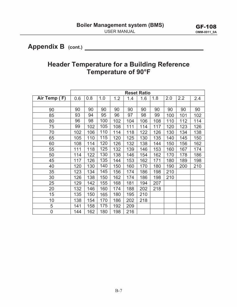
B-7
GF-108 OMM-0011_0A
Boiler Management system (BMS) g y ( )USER MANUAL
Appendix B (cont.) _________________________
Header Temperature for a Building Reference Temperature of 90°F
Reset Ratio Air Temp (°F) 0.6 0.8 1.0 1.2 1.4 1.6 1.8 2.0 2.2 2.4
90 90 90 90 90 90 90 90 90 90 90 85 93 94 95 96 97 98 99 100 101 102 80 96 98 100 102 104 106 108 110 112 114 75 99 102 105 108 111 114 117 120 123 126 70 102 106 110 114 118 122 126 130 134 138 65 105 110 115 120 125 130 135 140 145 150 60 108 114 120 126 132 138 144 150 156 162 55 111 118 125 132 139 146 153 160 167 174 50 114 122 130 138 146 154 162 170 178 186 45 117 126 135 144 153 162 171 180 189 198 40 120 130 140 150 160 170 180 190 200 210 35 123 134 145 156 174 186 198 210 30 126 138 150 162 174 186 198 210 25 129 142 155 168 181 194 207 20 132 146 160 174 188 202 218 15 135 150 165 180 195 210 10 138 154 170 186 202 2185 141 158 175 192 209 0 144 162 180 198 216

GF-108 OMM-0011_0A
Boiler Management system (BMS) g y ( )USER MANUAL
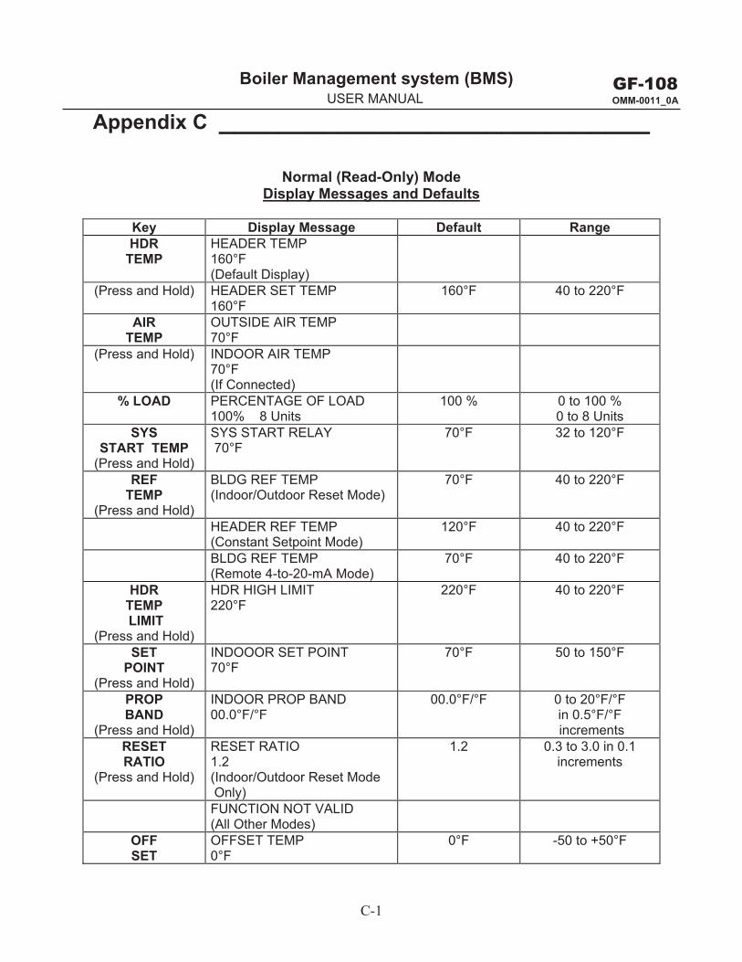
C-1
GF-108 OMM-0011_0A
Boiler Management system (BMS) g y ( )USER MANUAL
Appendix C _____________________________
Normal (Read-Only) Mode Display Messages and Defaults
Key Display Message Default RangeHDR
TEMP HEADER TEMP 160°F (Default Display)
(Press and Hold) HEADER SET TEMP 160°F
160°F 40 to 220°F
AIR TEMP
OUTSIDE AIR TEMP 70°F
(Press and Hold) INDOOR AIR TEMP 70°F (If Connected)
% LOAD PERCENTAGE OF LOAD 100% 8 Units
100 % 0 to 100 % 0 to 8 Units
SYS START TEMP
(Press and Hold)
SYS START RELAY 70°F
70°F 32 to 120°F
REF TEMP
(Press and Hold)
BLDG REF TEMP (Indoor/Outdoor Reset Mode)
70°F 40 to 220°F
HEADER REF TEMP (Constant Setpoint Mode)
120°F 40 to 220°F
BLDG REF TEMP (Remote 4-to-20-mA Mode)
70°F 40 to 220°F
HDR TEMP LIMIT
(Press and Hold)
HDR HIGH LIMIT 220°F
220°F 40 to 220°F
SET POINT
(Press and Hold)
INDOOOR SET POINT 70°F
70°F 50 to 150°F
PROP BAND
(Press and Hold)
INDOOR PROP BAND 00.0°F/°F
00.0°F/°F 0 to 20°F/°F in 0.5°F/°F increments
RESET RATIO
(Press and Hold)
RESET RATIO 1.2 (Indoor/Outdoor Reset Mode Only)
1.2 0.3 to 3.0 in 0.1 increments
FUNCTION NOT VALID (All Other Modes)
OFF SET
OFFSET TEMP 0°F
0°F -50 to +50°F

GF-108 OMM-0011_0A
Boiler Management system (BMS) g y ( )USER MANUAL
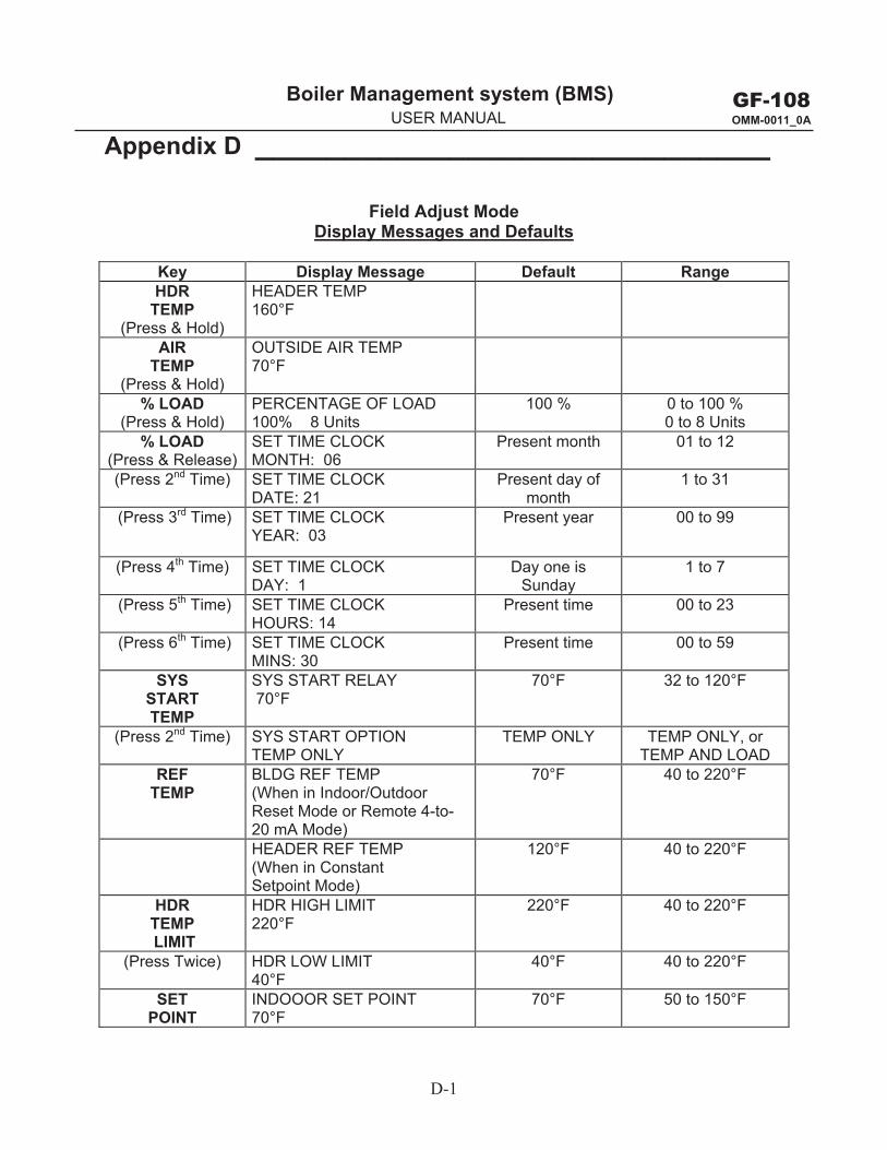
D-1
GF-108 OMM-0011_0A
Boiler Management system (BMS) g y ( )USER MANUAL
Appendix D _____________________________
Field Adjust Mode Display Messages and Defaults
Key Display Message Default RangeHDR
TEMP (Press & Hold)
HEADER TEMP 160°F
AIR TEMP
(Press & Hold)
OUTSIDE AIR TEMP 70°F
% LOAD (Press & Hold)
PERCENTAGE OF LOAD 100% 8 Units
100 % 0 to 100 % 0 to 8 Units
% LOAD (Press & Release)
SET TIME CLOCK MONTH: 06
Present month 01 to 12
(Press 2nd Time) SET TIME CLOCK DATE: 21
Present day of month
1 to 31
(Press 3rd Time) SET TIME CLOCKYEAR: 03
Present year 00 to 99
(Press 4th Time) SET TIME CLOCK DAY: 1
Day one is Sunday
1 to 7
(Press 5th Time) SET TIME CLOCK HOURS: 14
Present time 00 to 23
(Press 6th Time) SET TIME CLOCK MINS: 30
Present time 00 to 59
SYS START TEMP
SYS START RELAY 70°F
70°F 32 to 120°F
(Press 2nd Time) SYS START OPTION TEMP ONLY
TEMP ONLY TEMP ONLY, or TEMP AND LOAD
REF TEMP
BLDG REF TEMP (When in Indoor/Outdoor Reset Mode or Remote 4-to-20 mA Mode)
70°F 40 to 220°F
HEADER REF TEMP (When in Constant Setpoint Mode)
120°F 40 to 220°F
HDR TEMP LIMIT
HDR HIGH LIMIT 220°F
220°F 40 to 220°F
(Press Twice) HDR LOW LIMIT 40°F
40°F 40 to 220°F
SET POINT
INDOOOR SET POINT 70°F
70°F 50 to 150°F
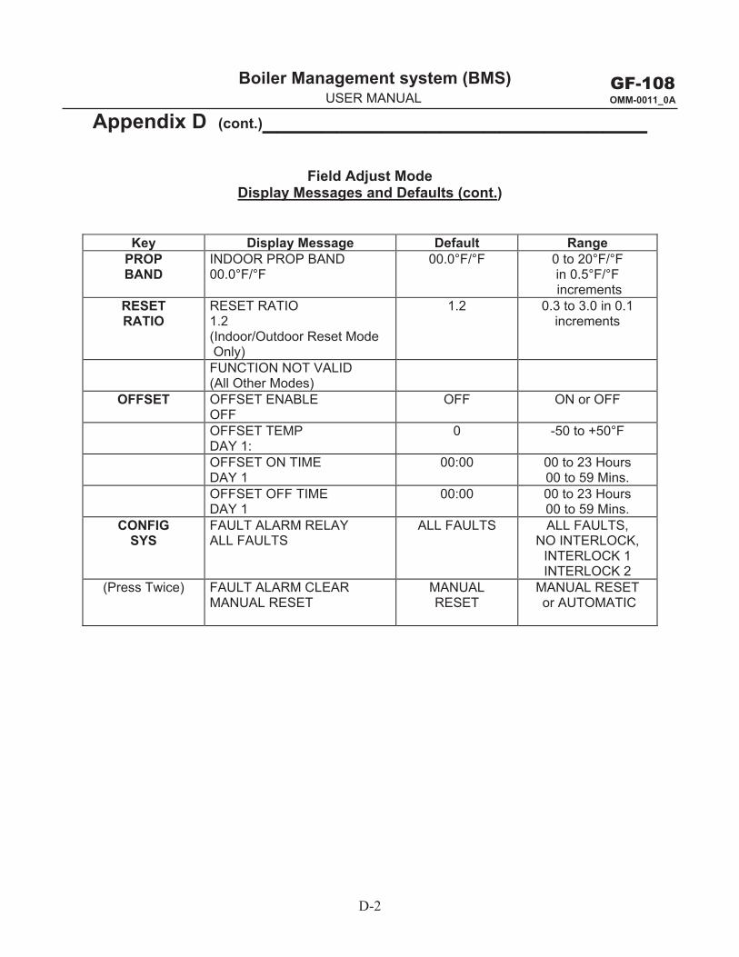
D-2
GF-108 OMM-0011_0A
Boiler Management system (BMS) g y ( )USER MANUAL
Appendix D (cont.)__________________________
Field Adjust Mode Display Messages and Defaults (cont.)
Key Display Message Default RangePROP BAND
INDOOR PROP BAND 00.0°F/°F
00.0°F/°F 0 to 20°F/°F in 0.5°F/°F increments
RESET RATIO
RESET RATIO 1.2 (Indoor/Outdoor Reset Mode Only)
1.2 0.3 to 3.0 in 0.1 increments
FUNCTION NOT VALID (All Other Modes)
OFFSET OFFSET ENABLE OFF
OFF ON or OFF
OFFSET TEMP DAY 1:
0 -50 to +50°F
OFFSET ON TIME DAY 1
00:00 00 to 23 Hours 00 to 59 Mins.
OFFSET OFF TIME DAY 1
00:00 00 to 23 Hours 00 to 59 Mins.
CONFIG SYS
FAULT ALARM RELAY ALL FAULTS
ALL FAULTS ALL FAULTS, NO INTERLOCK,
INTERLOCK 1 INTERLOCK 2
(Press Twice) FAULT ALARM CLEAR MANUAL RESET
MANUAL RESET
MANUAL RESET or AUTOMATIC
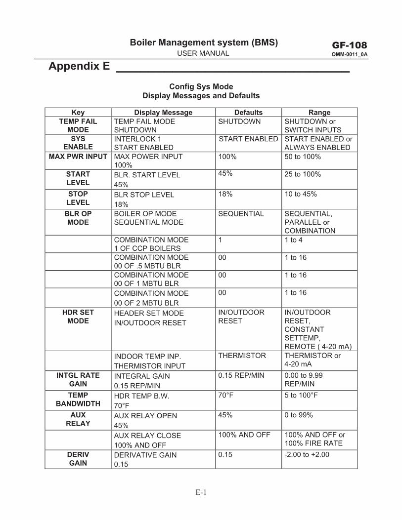
E-1
GF-108 OMM-0011_0A
Boiler Management system (BMS) g y ( )USER MANUAL
Appendix E _____________________________ Config Sys Mode
Display Messages and Defaults
Key Display Message Defaults Range TEMP FAIL
MODE TEMP FAIL MODE SHUTDOWN
SHUTDOWN SHUTDOWN or SWITCH INPUTS
SYS ENABLE
INTERLOCK 1 START ENABLED
START ENABLED START ENABLED or ALWAYS ENABLED
MAX PWR INPUT MAX POWER INPUT 100%
100% 50 to 100%
START LEVEL
BLR. START LEVEL 45%
45% 25 to 100%
STOP LEVEL
BLR STOP LEVEL 18%
18% 10 to 45%
BLR OP MODE
BOILER OP MODE SEQUENTIAL MODE
SEQUENTIAL SEQUENTIAL, PARALLEL or COMBINATION
COMBINATION MODE 1 OF CCP BOILERS
1 1 to 4
COMBINATION MODE 00 OF .5 MBTU BLR
00 1 to 16
COMBINATION MODE 00 OF 1 MBTU BLR
00 1 to 16
COMBINATION MODE 00 OF 2 MBTU BLR
00 1 to 16
HDR SET MODE
HEADER SET MODE IN/OUTDOOR RESET
IN/OUTDOOR RESET
IN/OUTDOOR RESET, CONSTANT SETTEMP, REMOTE ( 4-20 mA)
INDOOR TEMP INP. THERMISTOR INPUT
THERMISTOR THERMISTOR or 4-20 mA
INTGL RATE GAIN
INTEGRAL GAIN 0.15 REP/MIN
0.15 REP/MIN 0.00 to 9.99 REP/MIN
TEMP BANDWIDTH
HDR TEMP B.W. 70°F
70°F 5 to 100°F
AUX RELAY
AUX RELAY OPEN 45%
45% 0 to 99%
AUX RELAY CLOSE 100% AND OFF
100% AND OFF 100% AND OFF or100% FIRE RATE
DERIV GAIN
DERIVATIVE GAIN 0.15
0.15 -2.00 to +2.00

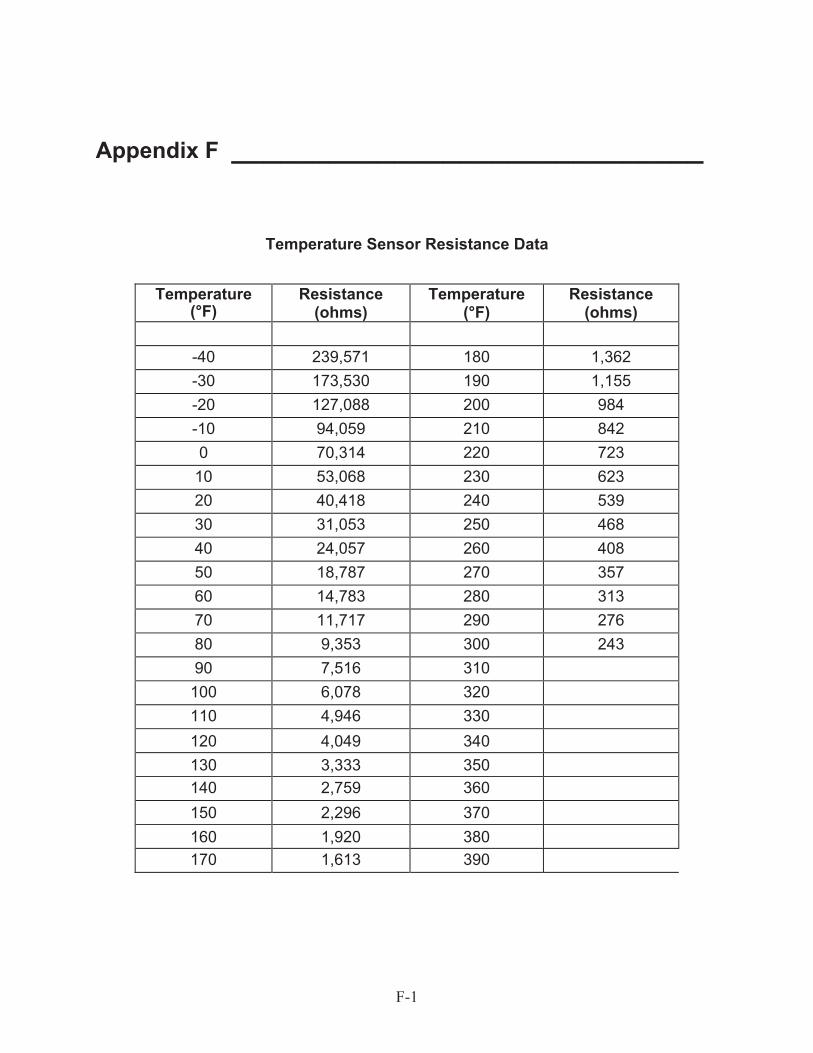
F-1
Appendix F _____________________________
Temperature Sensor Resistance Data
Temperature (°F)
Resistance (ohms)
Temperature (°F)
Resistance (ohms)
-40 239,571 180 1,362-30 173,530 190 1,155-20 127,088 200 984-10 94,059 210 8420 70,314 220 723
10 53,068 230 62320 40,418 240 53930 31,053 250 46840 24,057 260 40850 18,787 270 35760 14,783 280 31370 11,717 290 27680 9,353 300 24390 7,516 310
100 6,078 320110 4,946 330120 4,049 340130 3,333 350140 2,759 360150 2,296 370160 1,920 380170 1,613 390

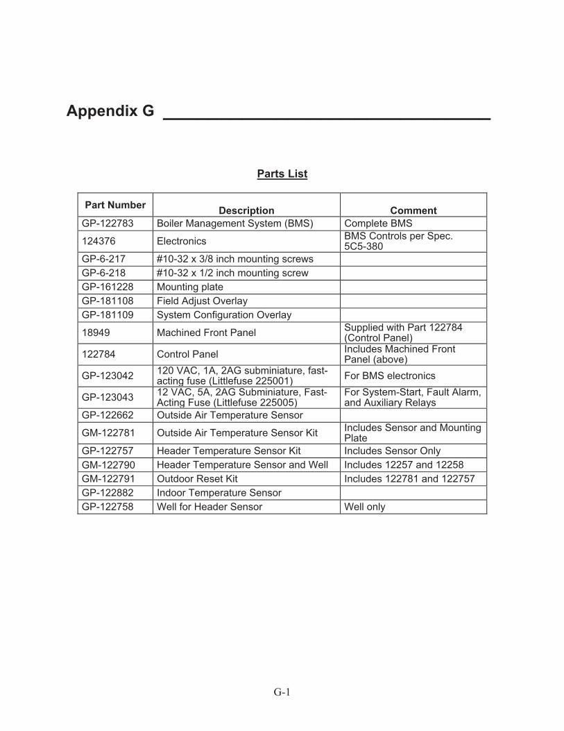
G-1
Appendix G _____________________________
Parts List
Part Number Description Comment GP-122783 Boiler Management System (BMS) Complete BMS
124376 Electronics BMS Controls per Spec. 5C5-380
GP-6-217 #10-32 x 3/8 inch mounting screws GP-6-218 #10-32 x 1/2 inch mounting screw GP-161228 Mounting plate GP-181108 Field Adjust Overlay GP-181109 System Configuration Overlay
18949 Machined Front Panel Supplied with Part 122784 (Control Panel)
122784 Control Panel Includes Machined Front Panel (above)
GP-123042 120 VAC, 1A, 2AG subminiature, fast-acting fuse (Littlefuse 225001) For BMS electronics
GP-123043 12 VAC, 5A, 2AG Subminiature, Fast-Acting Fuse (Littlefuse 225005)
For System-Start, Fault Alarm, and Auxiliary Relays
GP-122662 Outside Air Temperature Sensor
GM-122781 Outside Air Temperature Sensor Kit Includes Sensor and Mounting Plate
GP-122757 Header Temperature Sensor Kit Includes Sensor Only GM-122790 Header Temperature Sensor and Well Includes 12257 and 12258 GM-122791 Outdoor Reset Kit Includes 122781 and 122757 GP-122882 Indoor Temperature Sensor GP-122758 Well for Header Sensor Well only

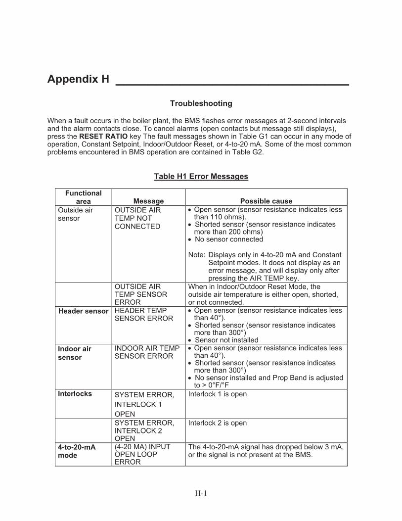
H-1
Appendix H _____________________________ Troubleshooting
When a fault occurs in the boiler plant, the BMS flashes error messages at 2-second intervals and the alarm contacts close. To cancel alarms (open contacts but message still displays), press the RESET RATIO key The fault messages shown in Table G1 can occur in any mode of operation, Constant Setpoint, Indoor/Outdoor Reset, or 4-to-20 mA. Some of the most common problems encountered in BMS operation are contained in Table G2.
Table H1 Error Messages
Functional area Message Possible cause
Outside air sensor
OUTSIDE AIR TEMP NOT CONNECTED
Open sensor (sensor resistance indicates less than 110 ohms).
Shorted sensor (sensor resistance indicates more than 200 ohms)
No sensor connected
Note: Displays only in 4-to-20 mA and Constant Setpoint modes. It does not display as an error message, and will display only after pressing the AIR TEMP key.
OUTSIDE AIR TEMP SENSOR ERROR
When in Indoor/Outdoor Reset Mode, the outside air temperature is either open, shorted, or not connected.
Header sensor HEADER TEMP SENSOR ERROR
Open sensor (sensor resistance indicates less than 40°).
Shorted sensor (sensor resistance indicates more than 300°)
Sensor not installed Indoor air sensor
INDOOR AIR TEMP SENSOR ERROR
Open sensor (sensor resistance indicates less than 40°).
Shorted sensor (sensor resistance indicates more than 300°)
No sensor installed and Prop Band is adjusted to > 0°F/°F
Interlocks SYSTEM ERROR, INTERLOCK 1 OPEN
Interlock 1 is open
SYSTEM ERROR, INTERLOCK 2 OPEN
Interlock 2 is open
4-to-20-mAmode
(4-20 MA) INPUT OPEN LOOP ERROR
The 4-to-20-mA signal has dropped below 3 mA, or the signal is not present at the BMS.
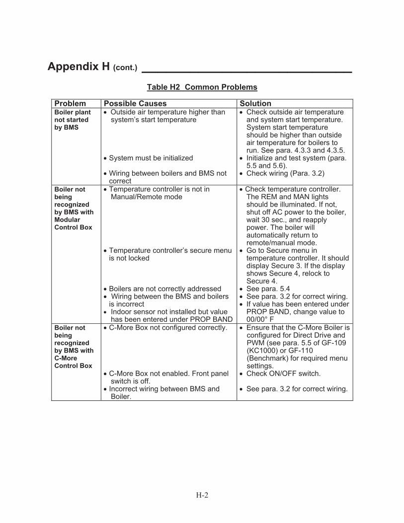
H-2
Appendix H (cont.) __________________________
Table H2 Common Problems
Problem Possible Causes Solution Boiler plant not started by BMS
Outside air temperature higher than system’s start temperature
System must be initialized Wiring between boilers and BMS not correct
Check outside air temperature and system start temperature. System start temperature should be higher than outside air temperature for boilers to run. See para. 4.3.3 and 4.3.5.
Initialize and test system (para. 5.5 and 5.6).
Check wiring (Para. 3.2)
Boiler not being recognized by BMS with Modular Control Box
Temperature controller is not in Manual/Remote mode
Temperature controller’s secure menu is not locked
Boilers are not correctly addressed Wiring between the BMS and boilers is incorrect
Indoor sensor not installed but value has been entered under PROP BAND
Check temperature controller. The REM and MAN lights should be illuminated. If not, shut off AC power to the boiler, wait 30 sec., and reapply power. The boiler will automatically return to remote/manual mode.
Go to Secure menu in temperature controller. It should display Secure 3. If the display shows Secure 4, relock to Secure 4.
See para. 5.4 See para. 3.2 for correct wiring. If value has been entered under PROP BAND, change value to 00/00° F
Boiler not being recognized by BMS with C-More Control Box
C-More Box not configured correctly.
C-More Box not enabled. Front panel switch is off.
Incorrect wiring between BMS and Boiler.
Ensure that the C-More Boiler is configured for Direct Drive and PWM (see para. 5.5 of GF-109 (KC1000) or GF-110 (Benchmark) for required menu settings.
Check ON/OFF switch.
See para. 3.2 for correct wiring.
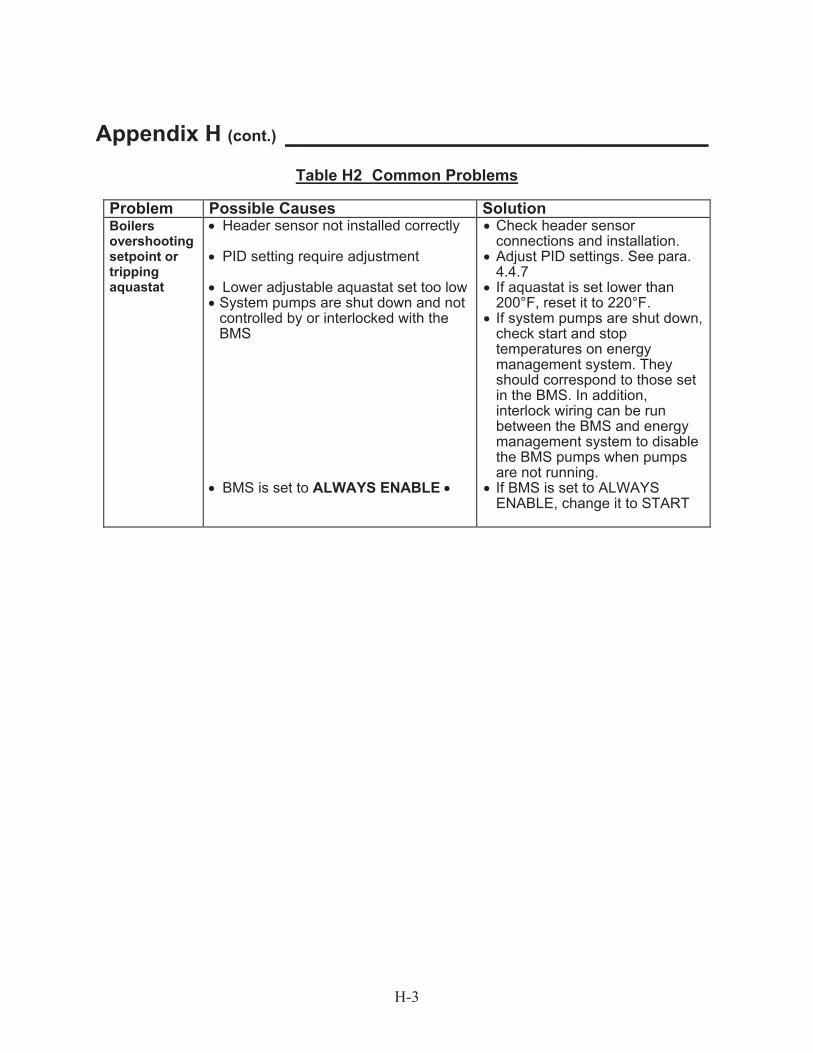
H-3
Appendix H (cont.) __________________________ Table H2 Common Problems
Problem Possible Causes Solution Boilers overshooting setpoint or tripping aquastat
Header sensor not installed correctly
PID setting require adjustment
Lower adjustable aquastat set too low System pumps are shut down and not controlled by or interlocked with the BMS
BMS is set to ALWAYS ENABLE
Check header sensor connections and installation.
Adjust PID settings. See para. 4.4.7
If aquastat is set lower than 200°F, reset it to 220°F.
If system pumps are shut down, check start and stop temperatures on energy management system. They should correspond to those set in the BMS. In addition, interlock wiring can be run between the BMS and energy management system to disable the BMS pumps when pumps are not running.
If BMS is set to ALWAYS ENABLE, change it to START

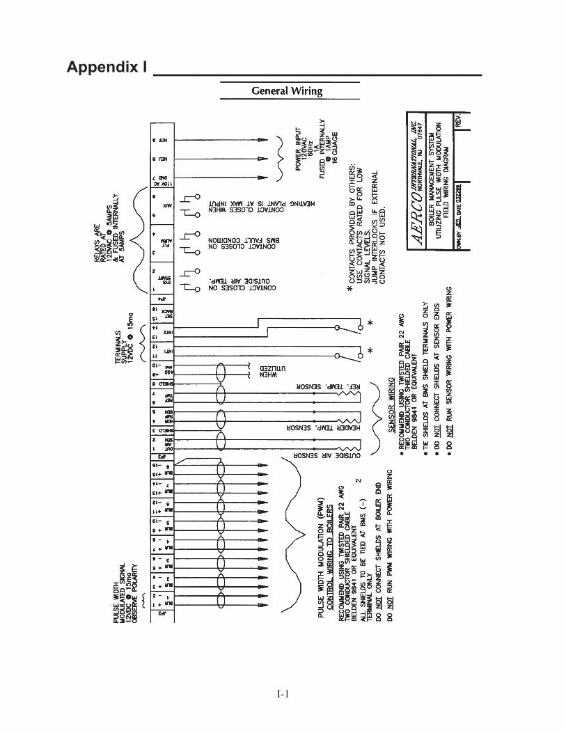
I-1
Appendix I _____________________________

J-1
Appendix J _____________________________
PROGRAMMING THE BMS USING RS-232 COMMUNICATION
Introduction The RS-232 port on the front panel of the BMS can be used to program the BMS using a laptop computer or other suitable terminal. Connection to a laptop or other terminal device is made using a 9-pin RS-232 adapter cable. Communication can be accomplished using any “Dumb Terminal” emulation, such as Hyper Terminal which is included with Microsoft Windows. The RS-232 communication feature allows the BMS to be easily programmed to your installation requirements using a listing of entry commands.
Set-Up Regardless of the terminal emulation utilized, the following guidelines must be adhered to when interfacing the BMS to the Terminal device:
1. Connect a 9-pin serial cable to the RS-232 connector near the lower left corner of the BMSfront panel.
2. Connect the free end of the cable to the COM 1 or COM 2 port on your laptop, or othersuitable terminal device.
3. Set up the emulator communication link as follows:
(a) Set the baud rate to 9600.
(b) Set the data format to 8 bits, 1 stop bit, no parity and either Xon/Xoff or No Flow Control.
4. Turn on the BMS by pressing the ON key. Verify that the ON LED lights.
5. Start the emulator software program.
6. At the command prompt, enter the password EXACTLY as follows (case-sensitive):
P=gobms
7. Press Return (<Rtn>) on your terminal.
8. The setup is now complete. You are ready to begin viewing or changing BMS functions.
J-2
Appendix J (cont.) __________________________
Programming Procedure BMS functions which can be viewed or changed are listed in Table J-1 along with their corresponding command numbers. Functions which can only be viewed (such as actual sensor readings) are marked “Read Only”. Viewing or changing function values is accomplished as follows:
1. Select the number of the desired command from Table J-1.
2. To view a parameter, type ?, followed by the command number and then press return (<Rtn>). For example, to view command no. 00 (HEADER TEMPERATURE), enter: ?00<Rtn> The header temperature reading will be displayed. All temperature readings are in °F.
3. To program (set) a BMS parameter, type @, followed by the command number, an equal sign, the parameter value and a trailing zero. For example, to set command 05 (SYSTEM OUTSIDE AIR START TEMPERATURE) to 65°F, enter: @05=650<Rtn>
Use the above steps to view and/or program the desired BMS functions listed in Table J-1.
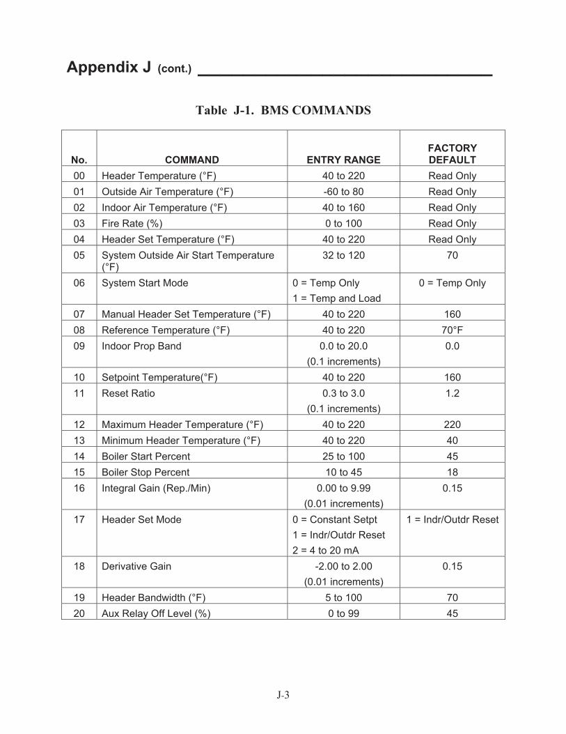
J-3
Appendix J (cont.) __________________________
Table J-1. BMS COMMANDS
No. COMMAND ENTRY RANGE FACTORY DEFAULT
00 Header Temperature (°F) 40 to 220 Read Only 01 Outside Air Temperature (°F) -60 to 80 Read Only 02 Indoor Air Temperature (°F) 40 to 160 Read Only 03 Fire Rate (%) 0 to 100 Read Only 04 Header Set Temperature (°F) 40 to 220 Read Only 05 System Outside Air Start Temperature
(°F) 32 to 120 70
06 System Start Mode 0 = Temp Only 1 = Temp and Load
0 = Temp Only
07 Manual Header Set Temperature (°F) 40 to 220 160 08 Reference Temperature (°F) 40 to 220 70°F 09 Indoor Prop Band 0.0 to 20.0
(0.1 increments) 0.0
10 Setpoint Temperature(°F) 40 to 220 160 11 Reset Ratio 0.3 to 3.0
(0.1 increments) 1.2
12 Maximum Header Temperature (°F) 40 to 220 220 13 Minimum Header Temperature (°F) 40 to 220 40 14 Boiler Start Percent 25 to 100 45 15 Boiler Stop Percent 10 to 45 18 16 Integral Gain (Rep./Min) 0.00 to 9.99
(0.01 increments) 0.15
17 Header Set Mode 0 = Constant Setpt 1 = Indr/Outdr Reset 2 = 4 to 20 mA
1 = Indr/Outdr Reset
18 Derivative Gain -2.00 to 2.00(0.01 increments)
0.15
19 Header Bandwidth (°F) 5 to 100 70 20 Aux Relay Off Level (%) 0 to 99 45
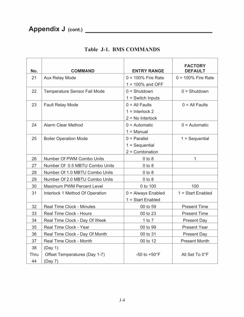
J-4
Appendix J (cont.) __________________________
Table J-1. BMS COMMANDS
No.
COMMAND
ENTRY RANGE
FACTORY DEFAULT
21 Aux Relay Mode 0 = 100% Fire Rate 1 = 100% and OFF
0 = 100% Fire Rate
22 Temperature Sensor Fail Mode 0 = Shutdown 1 = Switch Inputs
0 = Shutdown
23 Fault Relay Mode 0 = All Faults 1 = Interlock 2 2 = No Interlock
0 = All Faults
24 Alarm Clear Method 0 = Automatic 1 = Manual
0 = Automatic
25 Boiler Operation Mode 0 = Parallel 1 = Sequential 2 = Combination
1 = Sequential
26 Number Of PWM Combo Units 0 to 8 1 27 Number Of 0.5 MBTU Combo Units 0 to 8 28 Number Of 1.0 MBTU Combo Units 0 to 8 29 Number Of 2.0 MBTU Combo Units 0 to 8 30 Maximum PWM Percent Level 0 to 100 100 31 Interlock 1 Method Of Operation 0 = Always Enabled
1 = Start Enabled 1 = Start Enabled
32 Real Time Clock - Minutes 00 to 59 Present Time 33 Real Time Clock - Hours 00 to 23 Present Time 34 Real Time Clock - Day Of Week 1 to 7 Present Day 35 Real Time Clock - Year 00 to 99 Present Year 36 Real Time Clock - Day Of Month 00 to 31 Present Day 37 Real Time Clock - Month 00 to 12 Present Month 38 (Day 1)
Thru Offset Temperatures (Day 1-7) -50 to +50°F All Set To 0°F 44 (Day 7)
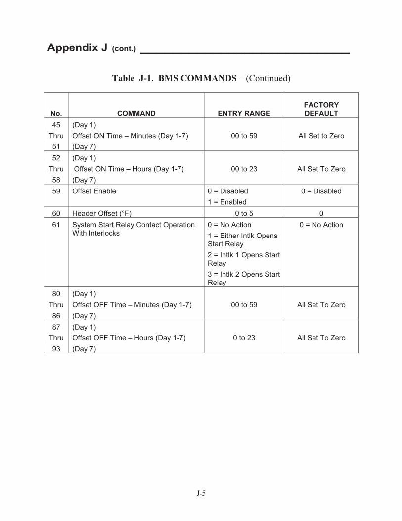
J-5
Appendix J (cont.) __________________________
Table J-1. BMS COMMANDS – (Continued)
No. COMMAND ENTRY RANGE FACTORY DEFAULT
45 (Day 1) Thru Offset ON Time – Minutes (Day 1-7) 00 to 59 All Set to Zero 51 (Day 7) 52 (Day 1)
Thru Offset ON Time – Hours (Day 1-7) 00 to 23 All Set To Zero 58 (Day 7) 59 Offset Enable 0 = Disabled
1 = Enabled 0 = Disabled
60 Header Offset (°F) 0 to 5 0 61 System Start Relay Contact Operation
With Interlocks 0 = No Action 1 = Either Intlk Opens Start Relay 2 = Intlk 1 Opens Start Relay 3 = Intlk 2 Opens Start Relay
0 = No Action
80 (Day 1) Thru Offset OFF Time – Minutes (Day 1-7) 00 to 59 All Set To Zero 86 (Day 7) 87 (Day 1)
Thru Offset OFF Time – Hours (Day 1-7) 0 to 23 All Set To Zero 93 (Day 7)