Embed Size (px)
Citation preview
Composite Structures 176 (2017) 547–555
Contents lists available at ScienceDirect
Composite Structures
journal homepage: www.elsevier .com/locate /compstruct
Bond interface design for single lap joints using polymeric additivemanufacturing
http://dx.doi.org/10.1016/j.compstruct.2017.05.0600263-8223/� 2017 Elsevier Ltd. All rights reserved.
⇑ Corresponding author at: 2210 Engineering Hall, 1415 Engineering Drive,Madison, WI 53706, USA.
E-mail address: [email protected] (P. Prabhakar).
R. Garcia a, P. Prabhakar b,⇑aDepartment of Mechanical Engineering, University of Texas at El Paso, El Paso, TX 79968, USAbDepartment of Civil & Env. Engineering, University of Wisconsin-Madison, Madison, WI 53706, USA
a r t i c l e i n f o
Article history:Received 6 December 2016Revised 18 March 2017Accepted 23 May 2017Available online 31 May 2017
Keywords:Single lap jointsAdhesively bonded jointsApparent shear strengthPolymer additive manufacturingFinite element stress analysis
a b s t r a c t
In this paper, the use of polymer additive manufacturing technology, also called 3D printing, for impart-ing texture to bond regions in adhesively bonded joints is explored. An improvement in the apparentshear strength values of adhesively bonded single lap joints is achieved by fusing structural reinforce-ments to the adherents through fused deposition modeling (FDM) additive technique. Towards that, com-putational models were first developed to simulate stress distribution along the overlap region of singlelap shear joints, and four models that performed the best were chosen for physical testing. Pure adhesive(PA) joints were manufactured first, followed by the fabrication of 3D-printed adhesive (3D-PA) joints.Peak loads, shear stresses, and failure types were compared between these models. PA joints failedmainly adhesively, resulting in low peak loads and shear strength, whereas, 3D-PA joints registeredhigher average peak loads and shear strengths (increased by up to �832 %) with predominantly cohesivefailure. 3D printed reinforcements appear to have imparted higher shear resistance against failure at thebond regions. Overall, using a combined computational and experimental approach, it is established thatthe 3D printed reinforcements have the potential to drastically improve the apparent shear strength ofadhesively bonded single lap joints.
� 2017 Elsevier Ltd. All rights reserved.
1. Introduction
Automotive and aerospace industries, amongst many others,are exploring routes to improve the quality of joints in an assem-bled component. Joints are critical regions in structures due tothe stress concentrations manifested compared to the membersof a component. With increasing applications of fiber reinforcedpolymer matrix composites (FRPCs) in aircrafts, navy structuresand automobiles, novel joining technology to assist the fabricationof large components has become a priority for structural engineers.Conventional materials such as steel or aluminum are joined usingfasteners and/or bolted joints, which are not favorable for FRPCs asdrilling or cutting may damage fibers causing an adverse effect ontheir structural integrity. Thus, adhesively bonded joints arebecoming a viable option for joining FRPCs.
Advantages of bonded joints over traditional mechanical fasten-ers are lower structural weight and improved damage tolerance.Despite these advantages, bonded joints in primary load-bearingapplications often result in overdesign due to the inclusion of
mechanical fasteners for additional safety. This is due to the lackof confidence in adhesively bonded joints for composite joiningtechnology. Mechanics based designs for bonded joints are neces-sary to facilitate efficient use of composites for lightweight applica-tions. This paper presents the use of additive manufacturing toimprove the mechanical behavior of bonded joints by enhancingthe load bearing capacity of the bond area.
Aerospace industry was the first to conduct work on adhesivelybonded joints in the 1970–80s. An extensive review on the jointstrength of adhesive joints for fiber reinforced composites was pro-vided by Matthews et al. [1]. The bond strength for FRPCs dependson various parameters, like, joint configuration, adhesive proper-ties, surface preparation, test methods, environmental conditions,etc. Of these, surface preparation is perhaps one of the most criticalin governing the quality of the joint [2]. According to Davis andBond [3], surface treatment with favorable surface chemistry priorto bonding can result in significant increase in the bond strengthresulting in improved durability of adhesive bonds. In order toensure maximum bond strength, abrasion/solvent cleaning tech-niques are commonly employed as surface treatment for ther-moset composites, like carbon/epoxy or glass/epoxy composites.Other viable options for surface treatments are, grit blasting, acid
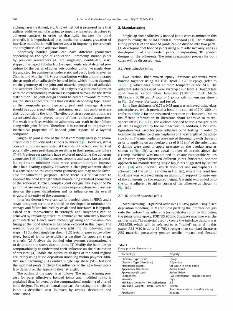
Table 1Epoxy product characteristics.
Technology Property
Chemical Type (Resin) EpoxyChemical Type (Hardener) PolyamideAppearance (Resin) Off-white to beige liquidAppearance (Hardener) Amber liquidAppearance (Mixed) Amber-BeigeComponents Two component – requires mixingViscosity HighMix Ratio (volume) – Resin:Hardener 2:1Mix Ratio (weight) – Resin:Hardener 100:46Cure Room temperature cure after mixingApplication Bonding
548 R. Garcia, P. Prabhakar / Composite Structures 176 (2017) 547–555
etching, laser treatment, etc. A novel method is proposed here thatutilizes additive manufacturing to impart engineered structure toadherent surfaces in order to drastically increase the bondstrength. It is hypothesized that mechanics dictated gradation ofinterface modification will further assist in improving the strengthand toughness of the adhesive bond.
Adhesively bonded joints can have different geometriesdepending on the type of application. Commonly studied jointsby previous researchers [4] are single-lap, double-lap, scarf,stepped, T-shaped, tubular lap, L-shaped joints, etc. A detailed pro-cedure for the design of adhesively bonded joints, like single, dou-ble and step, for composites under static and cyclic loads is given inChamis and Murthy [5]. Stress distribution within a joint dictatesthe strength of an adhesively bonded joint, which in turn dependson the geometry of the joint and material properties of adhesiveand adherent. Therefore, a detailed analysis of a joint configurationwith the corresponding materials is required to evaluate the stressdistribution. The joint design should be catered towards minimiz-ing the stress concentrations that catalyze debonding type failureat the composite joint. Especially, peel and cleavage stressesshould be suppressed, while maintaining an almost uniform stressdistribution along the joint. The effects of stress concentrations areaccentuated due to layered nature of fiber reinforced composites.The weak interfaces within the adherents can result in their failurealong with joint failure. Therefore, it is essential to improve themechanical properties of bonded joint regions of a layeredcomposite.
Single-lap joint is one of the most commonly used joint geom-etry due its simplicity and easiness to fabricate [6]. However, stressconcentrations are manifested at the ends of the bond overlap thatpotentially cause peel damage resulting in their premature failure[7–9]. Previous researchers have explored modifying the adherentgeometries [10–12], like tapering, stepping and wavy lap, as possi-ble options to minimize these stress concentrations to improvetheir load bearing capacity. However, a changing adherent shapeis a constraint on the component geometry and may not be favor-able for fabrication purposes. Hence, there is a critical need toimprove the bond strength while maintaining standard geometriesof the adherent. Further, complex joint designs, like T-joint or Pi-joint, that are used to join composites require extensive investiga-tion on the stress distribution and its influence on the overallstructural integrity of the component.
Interface design is very critical for bonded joints in FRPCs and asmart designing technique should be developed to minimize thedamage and failure incurred by weak bond interfaces. It is hypoth-esized that improvement in strength and toughness can beachieved by imparting structural texture at the adhesively bondedjoint interfaces. Hence, novel technology using additive manufac-turing at the bond interfaces has been explored in this paper. Theresearch reported in this paper was split into the following mainsteps: (1) Conduct single lap shear (SLS) tests on pure epoxy adhe-sively bonded joints to establish a baseline for apparent shearstrength; (2) Analyze the bonded joint systems computationallyto determine the stress distributions; (3) Modify the bond designcomputationally to understand their influence on the distributionof stresses; (4) Enable the optimum designs at the bond regionsaccurately using fused deposition modeling within polymer addi-tive manufacturing; (5) Conduct single lap shear (SLS) tests onthe modified joints to check the influence of the new bond inter-face designs on the apparent shear strength.
The outline of the paper is as follows: The manufacturing pro-cess for pure adhesively bonded joints and modified joints isexplained first, followed by the computational modeling of alteredbond designs. The experimental approach for testing the single lapjoints is described next followed by results, discussion andconclusions.
2. Manufacturing
Single lap shear adhesively bonded joints were examined in thispaper following the ASTM D5868-01 standard [13]. The manufac-turing process of the bonded joints can be divided into two parts:(1) development of bonded joints using pure adhesive only, and (2)development of the bonded joints incorporating 3D printeddesigns on the adherents. The joint preparation process for bothcases will be discussed next.
2.1. Pure adhesive joints
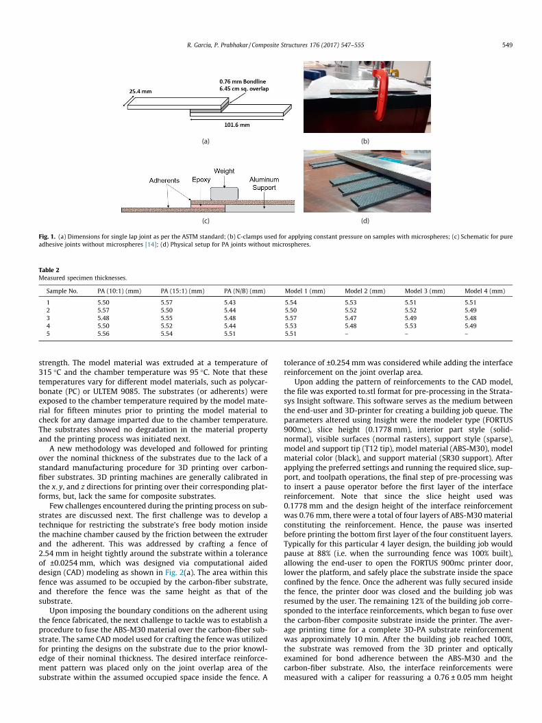
Two carbon fiber woven epoxy laminate adherents werebonded together using LOCTITE Hysol E-120HP epoxy (refer toTable 1), which was cured at room temperature for 24 h. Theadherent substrates used were water-jet cut from a DragonPlatesolid woven carbon fiber laminate (2.38 mm thick Matte30.48 cm � 60.96 cm). A total of 5 joints with dimensions shownin Fig. 1(a) were fabricated and tested.
Bond line thickness of 0.76 ± 0.05 mm was achieved using glassmicrospheres, which provided a bond line control of 700–800 lm(refer to Table 2 for the measured specimen thicknesses). Due toinsufficient information in literature about adhesive to micro-sphere ratio [15,16,13], the authors decided to use a weight ratioof 10:1 as suggested by the manufacturer. In addition, a 15:1 con-figuration was used for pure adhesive bond testing in order toexamine the influence of microspheres on the strength of the adhe-sive bond. The microspheres were mixed thoroughly with the resinprior to applying on an overlap area of 6.45 cm2 of the substrates.C-clamps were used to apply pressure on the overlap area asshown in Fig. 1(b), where equal number of threads above thec-clamp overhead was maintained to ensure comparable valuesof pressure applied between different joints fabricated. Anotherapproach for manufacturing single lap joints suggested by Boutaret al. [14] was followed, which does not use microspheres. Aschematic of the setup is shown in Fig. 1(c), where the bond linethickness was achieved using an aluminum support to raise oneof the adherents by the required height. A weight was added ontothe same adherent to aid in curing of the adhesive as shown inFig. 1(d).
2.2. 3D-printed adhesive joints
Manufacturing 3D-printed adhesive (3D-PA) joints using fuseddeposition modeling (FDM) required printing the interface designsonto the carbon fiber adherents (or substrates) prior to fabricatingthe joints using epoxy. FORTUS 900mc Stratasys machine was theprinter used. The material used to create the interface designs wasABS-M30, which will be referred to as ‘‘model” material in thispaper. ABS-M30 is up to 25–70% stronger than standard StratasysABS material, possessing greater tensile, impact, and flexural
(a) (b)
(c) (d)
Fig. 1. (a) Dimensions for single lap joint as per the ASTM standard; (b) C-clamps used for applying constant pressure on samples with microspheres; (c) Schematic for pureadhesive joints without microspheres [14]; (d) Physical setup for PA joints without microspheres.
Table 2Measured specimen thicknesses.
Sample No. PA (10:1) (mm) PA (15:1) (mm) PA (N/B) (mm) Model 1 (mm) Model 2 (mm) Model 3 (mm) Model 4 (mm)
1 5.50 5.57 5.43 5.54 5.53 5.51 5.512 5.57 5.50 5.44 5.50 5.52 5.52 5.493 5.48 5.55 5.48 5.57 5.47 5.49 5.484 5.50 5.52 5.44 5.53 5.48 5.53 5.495 5.56 5.54 5.51 5.51 – – –
R. Garcia, P. Prabhakar / Composite Structures 176 (2017) 547–555 549
strength. The model material was extruded at a temperature of315 �C and the chamber temperature was 95 �C. Note that thesetemperatures vary for different model materials, such as polycar-bonate (PC) or ULTEM 9085. The substrates (or adherents) wereexposed to the chamber temperature required by the model mate-rial for fifteen minutes prior to printing the model material tocheck for any damage imparted due to the chamber temperature.The substrates showed no degradation in the material propertyand the printing process was initiated next.
A new methodology was developed and followed for printingover the nominal thickness of the substrates due to the lack of astandard manufacturing procedure for 3D printing over carbon-fiber substrates. 3D printing machines are generally calibrated inthe x; y, and z directions for printing over their corresponding plat-forms, but, lack the same for composite substrates.
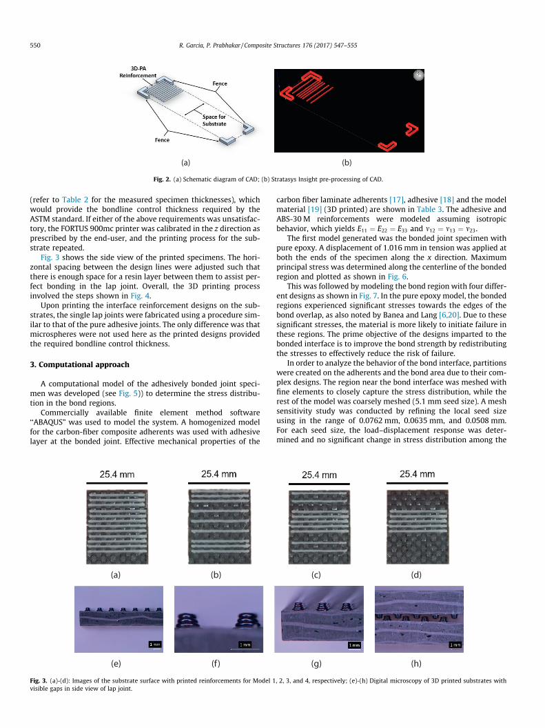
Few challenges encountered during the printing process on sub-strates are discussed next. The first challenge was to develop atechnique for restricting the substrate’s free body motion insidethe machine chamber caused by the friction between the extruderand the adherent. This was addressed by crafting a fence of2.54 mm in height tightly around the substrate within a toleranceof ±0.0254 mm, which was designed via computational aideddesign (CAD) modeling as shown in Fig. 2(a). The area within thisfence was assumed to be occupied by the carbon-fiber substrate,and therefore the fence was the same height as that of thesubstrate.
Upon imposing the boundary conditions on the adherent usingthe fence fabricated, the next challenge to tackle was to establish aprocedure to fuse the ABS-M30 material over the carbon-fiber sub-strate. The same CADmodel used for crafting the fence was utilizedfor printing the designs on the substrate due to the prior knowl-edge of their nominal thickness. The desired interface reinforce-ment pattern was placed only on the joint overlap area of thesubstrate within the assumed occupied space inside the fence. A
tolerance of ±0.254 mm was considered while adding the interfacereinforcement on the joint overlap area.
Upon adding the pattern of reinforcements to the CAD model,the file was exported to.stl format for pre-processing in the Strata-sys Insight software. This software serves as the medium betweenthe end-user and 3D-printer for creating a building job queue. Theparameters altered using Insight were the modeler type (FORTUS900mc), slice height (0.1778 mm), interior part style (solid-normal), visible surfaces (normal rasters), support style (sparse),model and support tip (T12 tip), model material (ABS-M30), modelmaterial color (black), and support material (SR30 support). Afterapplying the preferred settings and running the required slice, sup-port, and toolpath operations, the final step of pre-processing wasto insert a pause operator before the first layer of the interfacereinforcement. Note that since the slice height used was0.1778 mm and the design height of the interface reinforcementwas 0.76 mm, there were a total of four layers of ABS-M30 materialconstituting the reinforcement. Hence, the pause was insertedbefore printing the bottom first layer of the four constituent layers.Typically for this particular 4 layer design, the building job wouldpause at 88% (i.e. when the surrounding fence was 100% built),allowing the end-user to open the FORTUS 900mc printer door,lower the platform, and safely place the substrate inside the spaceconfined by the fence. Once the adherent was fully secured insidethe fence, the printer door was closed and the building job wasresumed by the user. The remaining 12% of the building job corre-sponded to the interface reinforcements, which began to fuse overthe carbon-fiber composite substrate inside the printer. The aver-age printing time for a complete 3D-PA substrate reinforcementwas approximately 10 min. After the building job reached 100%,the substrate was removed from the 3D printer and opticallyexamined for bond adherence between the ABS-M30 and thecarbon-fiber substrate. Also, the interface reinforcements weremeasured with a caliper for reassuring a 0.76 ± 0.05 mm height
(a) (b)
Fig. 2. (a) Schematic diagram of CAD; (b) Stratasys Insight pre-processing of CAD.
550 R. Garcia, P. Prabhakar / Composite Structures 176 (2017) 547–555
(refer to Table 2 for the measured specimen thicknesses), whichwould provide the bondline control thickness required by theASTM standard. If either of the above requirements was unsatisfac-tory, the FORTUS 900mc printer was calibrated in the z direction asprescribed by the end-user, and the printing process for the sub-strate repeated.
Fig. 3 shows the side view of the printed specimens. The hori-zontal spacing between the design lines were adjusted such thatthere is enough space for a resin layer between them to assist per-fect bonding in the lap joint. Overall, the 3D printing processinvolved the steps shown in Fig. 4.
Upon printing the interface reinforcement designs on the sub-strates, the single lap joints were fabricated using a procedure sim-ilar to that of the pure adhesive joints. The only difference was thatmicrospheres were not used here as the printed designs providedthe required bondline control thickness.
3. Computational approach
A computational model of the adhesively bonded joint speci-men was developed (see Fig. 5)) to determine the stress distribu-tion in the bond regions.
Commercially available finite element method software‘‘ABAQUS” was used to model the system. A homogenized modelfor the carbon-fiber composite adherents was used with adhesivelayer at the bonded joint. Effective mechanical properties of the
(a) (b)
(e) (f)
Fig. 3. (a)-(d): Images of the substrate surface with printed reinforcements for Model 1visible gaps in side view of lap joint.
carbon fiber laminate adherents [17], adhesive [18] and the modelmaterial [19] (3D printed) are shown in Table 3. The adhesive andABS-30 M reinforcements were modeled assuming isotropicbehavior, which yields E11 ¼ E22 ¼ E33 and m12 ¼ m13 ¼ m23.
The first model generated was the bonded joint specimen withpure epoxy. A displacement of 1.016 mm in tension was applied atboth the ends of the specimen along the x direction. Maximumprincipal stress was determined along the centerline of the bondedregion and plotted as shown in Fig. 6.
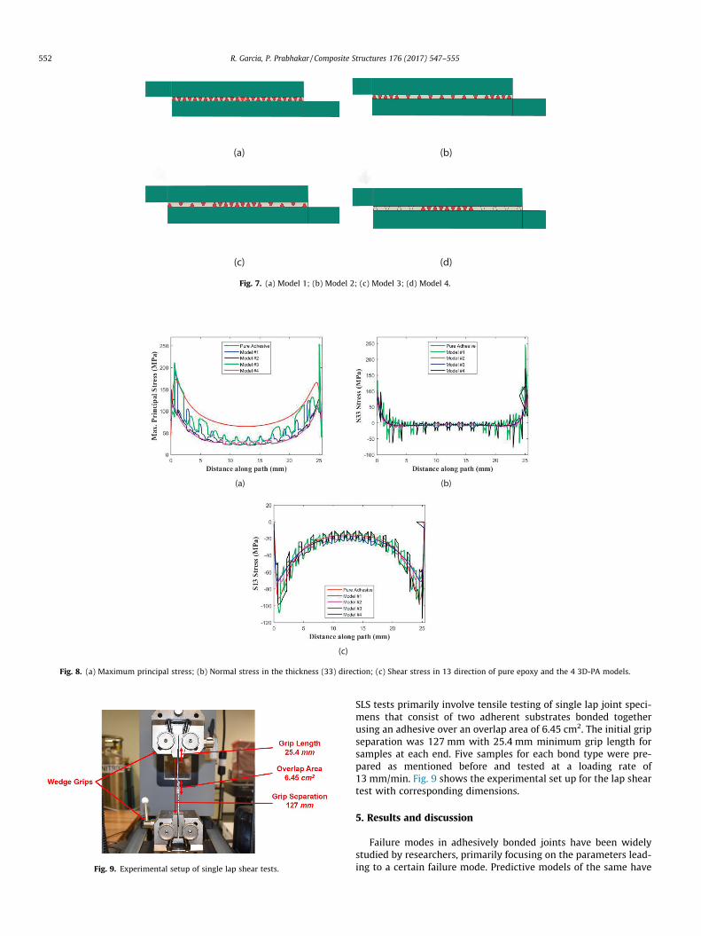
This was followed by modeling the bond region with four differ-ent designs as shown in Fig. 7. In the pure epoxy model, the bondedregions experienced significant stresses towards the edges of thebond overlap, as also noted by Banea and Lang [6,20]. Due to thesesignificant stresses, the material is more likely to initiate failure inthese regions. The prime objective of the designs imparted to thebonded interface is to improve the bond strength by redistributingthe stresses to effectively reduce the risk of failure.
In order to analyze the behavior of the bond interface, partitionswere created on the adherents and the bond area due to their com-plex designs. The region near the bond interface was meshed withfine elements to closely capture the stress distribution, while therest of the model was coarsely meshed (5.1 mm seed size). A meshsensitivity study was conducted by refining the local seed sizeusing in the range of 0.0762 mm, 0.0635 mm, and 0.0508 mm.For each seed size, the load–displacement response was deter-mined and no significant change in stress distribution among the
(c) (d)
(g) (h)
, 2, 3, and 4, respectively; (e)-(h) Digital microscopy of 3D printed substrates with
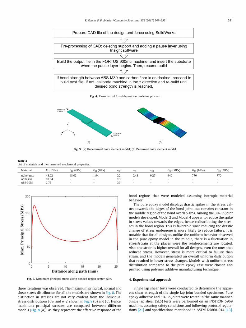
Fig. 4. Flowchart of fused deposition modeling process.
(a) (b)
Fig. 5. (a) Undeformed finite element model; (b) Deformed finite element model.
Fig. 6. Maximum principal stress along bonded region center path.
Table 3List of materials and their assumed mechanical properties.
Material E11 (GPa) E22 (GPa) E33 (GPa) m12 m13 m23 G12 (MPa) G13 (MPa) G23 (MPa)
Adherents 48.02 48.02 1.94 0.2 0.48 0.27 940 770 770Adhesive 10.34 – – 0.3 – – – – –ABS-30M 2.75 – – 0.3 – – – – –
R. Garcia, P. Prabhakar / Composite Structures 176 (2017) 547–555 551
three iterations was observed. The maximum principal, normal andshear stress distribution for all the models are shown in Fig. 8. Thedistinction in stresses are not very evident from the individualstress distributions (r33 and r13) shown in Fig. 8 (b) and (c). Hence,maximum principal stresses are compared between differentmodels (Fig. 8 (a)), as they represent the effective response of the
bond regions that were modeled assuming isotropic materialbehavior.
The pure epoxy model displays drastic spikes in the stress val-ues towards the edges of the bond joint, but remains constant inthe middle region of the bond overlap area. Among the 3D-PA jointmodels developed, Model 2 and Model 4 appear to reduce the spikein stress values towards the edges, hence redistributing the stres-ses in the bond region. This is favorable since reducing the drasticchange of stress undergone is more likely to reduce failure. It isnotable that for all designs, unlike the uniform behavior observedin the pure epoxy model in the middle, there is a fluctuation instress/strain at the places were the reinforcements are located.Also, the strain is higher overall for all designs, even the ones thatreduced stress. However, stress is more critical to failure thanstrain, and the models generated an overall uniform distributionthat resulted in lower stress changes. Models with uniform stressdistribution compared to the pure epoxy case were chosen andprinted using polymer additive manufacturing technique.
4. Experimental approach
Single lap shear tests were conducted to determine the appar-ent shear strength of the single lap joint bonded specimens. Pureepoxy adhesive and 3D-PA joints were tested in the same manner.Single lap shear (SLS) tests were performed on an INSTRON 5969machine, assuring safety conditions and following protocol regula-tions [21] and specifications mentioned in ASTM D5868-014 [13].
(a) (b)
(c) (d)
Fig. 7. (a) Model 1; (b) Model 2; (c) Model 3; (d) Model 4.
(a) (b)
(c)
Fig. 8. (a) Maximum principal stress; (b) Normal stress in the thickness (33) direction; (c) Shear stress in 13 direction of pure epoxy and the 4 3D-PA models.
Fig. 9. Experimental setup of single lap shear tests.
552 R. Garcia, P. Prabhakar / Composite Structures 176 (2017) 547–555
SLS tests primarily involve tensile testing of single lap joint speci-mens that consist of two adherent substrates bonded togetherusing an adhesive over an overlap area of 6.45 cm2. The initial gripseparation was 127 mm with 25.4 mm minimum grip length forsamples at each end. Five samples for each bond type were pre-pared as mentioned before and tested at a loading rate of13 mm/min. Fig. 9 shows the experimental set up for the lap sheartest with corresponding dimensions.
5. Results and discussion
Failure modes in adhesively bonded joints have been widelystudied by researchers, primarily focusing on the parameters lead-ing to a certain failure mode. Predictive models of the same have

Fig. 10. Failure modes in lap shear tests.
R. Garcia, P. Prabhakar / Composite Structures 176 (2017) 547–555 553
been developed by earlier researchers [15,22–24] to capture thedifferent failure mechanisms associated with adhesively bondedjoints. Commonly observed failure modes related to lap shear testsare shown in Fig. 10.
SLS test data obtained from each test was post-processed toultimately determine the apparent shear strength of the bondedjoints. The load–displacement responses for each joint type areshown in Fig. 11 (a)–(f), which were analyzed to determine thepeak load and energy absorbed by each sample. The limits of the
(a)
(c)
(e)
Fig. 11. Load vs. displacement responses for (a) PA (10:1), (b) PA (
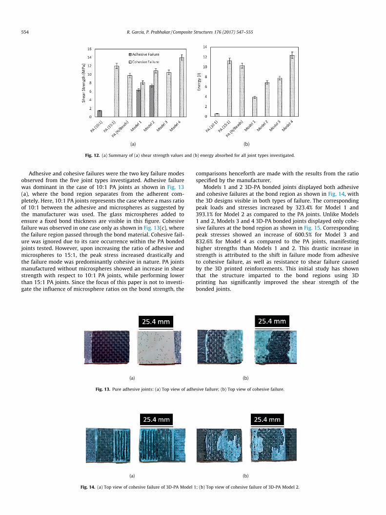
axes are maintained constant between the figures to display thedistinct differences in the response between different cases. Itcan be observed that 10:1 PA joints performed poorly as comparedto that of 15:1 PA and Model 4 joints, where the latter manifestedthe highest strength and energy among all joint types. Also, anincrease of 107.6%, 155.5%, 132.1%, and 130% in stiffness wasobserved in Models 1–4 as compared to that of 10:1 PA joints.However, when compared to 15:1 PA joints, Models 1–4 mani-fested a change of �3%, 19.3%, 8.5%, and 7.5%, respectively. Theprinted reinforcements appear to enhance the overall stiffness ofthe bonded joint. After assessing the load–displacement plots,the individual load values that were recorded by the operating loadcell were divided by the overlapping bond area to calculate theapparent shear strengths of the joints. The average and standarddeviation of shear strength values corresponding to adhesive andcohesive failure modes were independently determined followingASTM standards for each bond type, and are summarized inFig. 12 (a). The corresponding energy absorption values were alsocalculated by determining the area under the load–displacementresponses, and are summarized in Fig. 12 (b). A trend similar tothat of shear strengths among different configurations is observedin the case of energy absorption as well.
(b)
(d)
(f)
15:1), (c) Model 1, (d) Model 2, (e) Model 3, and (f) Model 4.
(a) (b)
Fig. 12. (a) Summary of (a) shear strength values and (b) energy absorbed for all joint types investigated.
554 R. Garcia, P. Prabhakar / Composite Structures 176 (2017) 547–555
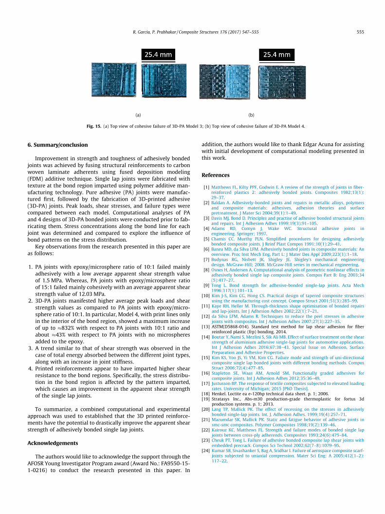
Adhesive and cohesive failures were the two key failure modesobserved from the five joint types investigated. Adhesive failurewas dominant in the case of 10:1 PA joints as shown in Fig. 13(a), where the bond region separates from the adherent com-pletely. Here, 10:1 PA joints represents the case where a mass ratioof 10:1 between the adhesive and microspheres as suggested bythe manufacturer was used. The glass microspheres added toensure a fixed bond thickness are visible in this figure. Cohesivefailure was observed in one case only as shown in Fig. 13(c), wherethe failure region passed through the bond material. Cohesive fail-ure was ignored due to its rare occurrence within the PA bondedjoints tested. However, upon increasing the ratio of adhesive andmicrospheres to 15:1, the peak stress increased drastically andthe failure mode was predominantly cohesive in nature. PA jointsmanufactured without microspheres showed an increase in shearstrength with respect to 10:1 PA joints, while performing lowerthan 15:1 PA joints. Since the focus of this paper is not to investi-gate the influence of microsphere ratios on the bond strength, the
(a)
Fig. 14. (a) Top view of cohesive failure of 3D-PA Model 1
(a)
Fig. 13. Pure adhesive joints: (a) Top view of adhe
comparisons henceforth are made with the results from the ratiospecified by the manufacturer.
Models 1 and 2 3D-PA bonded joints displayed both adhesiveand cohesive failures at the bond region as shown in Fig. 14, withthe 3D designs visible in both types of failure. The correspondingpeak loads and stresses increased by 323.4% for Model 1 and393.1% for Model 2 as compared to the PA joints. Unlike Models1 and 2, Models 3 and 4 3D-PA bonded joints displayed only cohe-sive failures at the bond region as shown in Fig. 15. Correspondingpeak stresses showed an increase of 600.5% for Model 3 and832.6% for Model 4 as compared to the PA joints, manifestinghigher strengths than Models 1 and 2. This drastic increase instrength is attributed to the shift in failure mode from adhesiveto cohesive failure, as well as resistance to shear failure causedby the 3D printed reinforcements. This initial study has shownthat the structure imparted to the bond regions using 3Dprinting has significantly improved the shear strength of thebonded joints.
(b)
; (b) Top view of cohesive failure of 3D-PA Model 2.
(b)
sive failure; (b) Top view of cohesive failure.
(a) (b)
Fig. 15. (a) Top view of cohesive failure of 3D-PA Model 3; (b) Top view of cohesive failure of 3D-PA Model 4.
R. Garcia, P. Prabhakar / Composite Structures 176 (2017) 547–555 555
6. Summary/conclusion
Improvement in strength and toughness of adhesively bondedjoints was achieved by fusing structural reinforcements to carbonwoven laminate adherents using fused deposition modeling(FDM) additive technique. Single lap joints were fabricated withtexture at the bond region imparted using polymer additive man-ufacturing technology. Pure adhesive (PA) joints were manufac-tured first, followed by the fabrication of 3D-printed adhesive(3D-PA) joints. Peak loads, shear stresses, and failure types werecompared between each model. Computational analyses of PAand 4 designs of 3D-PA bonded joints were conducted prior to fab-ricating them. Stress concentrations along the bond line for eachjoint was determined and compared to explore the influence ofbond patterns on the stress distribution.
Key observations from the research presented in this paper areas follows:
1. PA joints with epoxy/microsphere ratio of 10:1 failed mainlyadhesively with a low average apparent shear strength valueof 1.5 MPa. Whereas, PA joints with epoxy/microsphere ratioof 15:1 failed mainly cohesively with an average apparent shearstrength value of 12.03 MPa.
2. 3D-PA joints manifested higher average peak loads and shearstrength values as compared to PA joints with epoxy/micro-sphere ratio of 10:1. In particular, Model 4, with print lines onlyin the interior of the bond region, showed a maximum increaseof up to �832% with respect to PA joints with 10:1 ratio andabout �43% with respect to PA joints with no microspheresadded to the epoxy.
3. A trend similar to that of shear strength was observed in thecase of total energy absorbed between the different joint types,along with an increase in joint stiffness.
4. Printed reinforcements appear to have imparted higher shearresistance to the bond regions. Specifically, the stress distribu-tion in the bond region is affected by the pattern imparted,which causes an improvement in the apparent shear strengthof the single lap joints.
To summarize, a combined computational and experimentalapproach was used to established that the 3D printed reinforce-ments have the potential to drastically improve the apparent shearstrength of adhesively bonded single lap joints.
Acknowledgements
The authors would like to acknowledge the support through theAFOSR Young Investigator Program award (Award No.: FA9550-15-1-0216) to conduct the research presented in this paper. In
addition, the authors would like to thank Edgar Acuna for assistingwith initial development of computational modeling presented inthis work.
References
[1] Matthews FL, Kilty PPF, Godwin E. A review of the strength of joints in fiber-reinforced plastics 2: adhesively bonded joints. Composites 1982;13(1):29–37.
[2] Baldan A. Adhesively-bonded joints and repairs in metallic alloys, polymersand composite materials: adhesives, adhesion theories and surfacepretreatment. J Mater Sci 2004;39(1):1–49.
[3] Davis MJ, Bond D. Principles and practise of adhesive bonded structural jointsand repairs. Int J Adhesion Adhes 1999;19(3):91–105.
[4] Adams RD, Comyn J, Wake WC. Structural adhesive joints inengineering. Springer; 1997.
[5] Chamis CC, Murthy PLN. Simplified procedures for designing adhesivelybonded composite joints. J Reinf Plast Compos 1991;10(1):29–41.
[6] Banea MD, da Silva LFM. Adhesively bonded joints in composite materials: Anoverview. Proc Inst Mech Eng, Part L: J Mater Des Appl 2009;223(1):1–18.
[7] Budynas RG, Nisbett JK, Shigley JE. Shigley’s mechanical engineeringdesign. McGraw-Hill; 2008. McGraw-Hill series in mechanical engineering.
[8] Osnes H, Andersen A. Computational analysis of geometric nonlinear effects inadhesively bonded single lap composite joints. Compos Part B: Eng 2003;34(5):417–27.
[9] Tong L. Bond strength for adhesive-bonded single-lap joints. Acta Mech1996;117(1):101–13.
[10] Kim J-S, Kim CG, Hong CS. Practical design of tapered composite structuresusing the manufacturing cost concept. Compos Struct 2001;51(3):285–99.
[11] Kaye RH, Heller M. Through-thickness shape optimisation of bonded repairsand lap-joints. Int J Adhesion Adhes 2002;22(1):7–21.
[12] da Silva LFM, Adams R. Techniques to reduce the peel stresses in adhesivejoints with composites. Int J Adhesion Adhes 2007;27(3):227–35.
[13] ASTM(D5868-014). Standard test method for lap shear adhesion for fiberreinforced plastic (frp) bonding. 2014.
[14] Boutar Y, Nami S, Mezlini S, Sik Ali MB. Effect of surface treatment on the shearstrength of aluminium adhesive single-lap joints for automotive applications.Int J Adhesion Adhes 2016;67:38–43. Special Issue on Adhesion, SurfacePreparation and Adhesive Properties.
[15] Kim KS, Yoo JS, Yi YM, Kim CG. Failure mode and strength of uni-directionalcomposite single lap bonded joints with different bonding methods. ComposStruct 2006;72(4):477–85.
[16] Stapleton SE, Waas AM, Arnold SM. Functionally graded adhesives forcomposite joints. Int J Adhesion Adhes 2012;35:36–49.
[17] Justusson BP. The response of textile composites subjected to elevated loadingrates. University of Michigan; 2015 [PhD Thesis].
[18] Henkel. Loctite ea e-120hp technical data sheet. p. 1; 2006.[19] Stratasys Inc., Abs-m30 production-grade thermoplastic for fortus 3d
production systems. p. 1; 2013.[20] Lang TP, Mallick PK. The effect of recessing on the stresses in adhesively
bonded single-lap joints. Int. J. Adhesion Adhes. 1999;19(4):257–71.[21] Mazumdar SK, Mallick PK. Static and fatigue behavior of adhesive joints in
smc-smc composites. Polymer Composites 1998;19(2):139–46.[22] Kairouz KC, Matthews FL. Strength and failure modes of bonded single lap
joints between cross-ply adherends. Composites 1993;24(6):475–84.[23] Cheuk PT, Tong L. Failure of adhesive bonded composite lap shear joints with
embedded precrack. Compos Sci Technol 2002;62(7–8):1079–95.[24] Kumar SB, Sivashanker S, Bag A, Sridhar I. Failure of aerospace composite scarf-
joints subjected to uniaxial compression. Mater Sci Eng: A 2005;412(1–2):117–22.