Embed Size (px)
Citation preview
1
Bottlenecks in Biofuel Cell Research
Han YanSupervisor: Dr. Gu Xu
Date: Jan 28th,2009
2
Outline
Basics of Biofuel Cells
Newly found problem: pH gradient
Major obstacles
Proposed solutions
Our experiments
Results & a strange phenomenon
Summary and future work
3
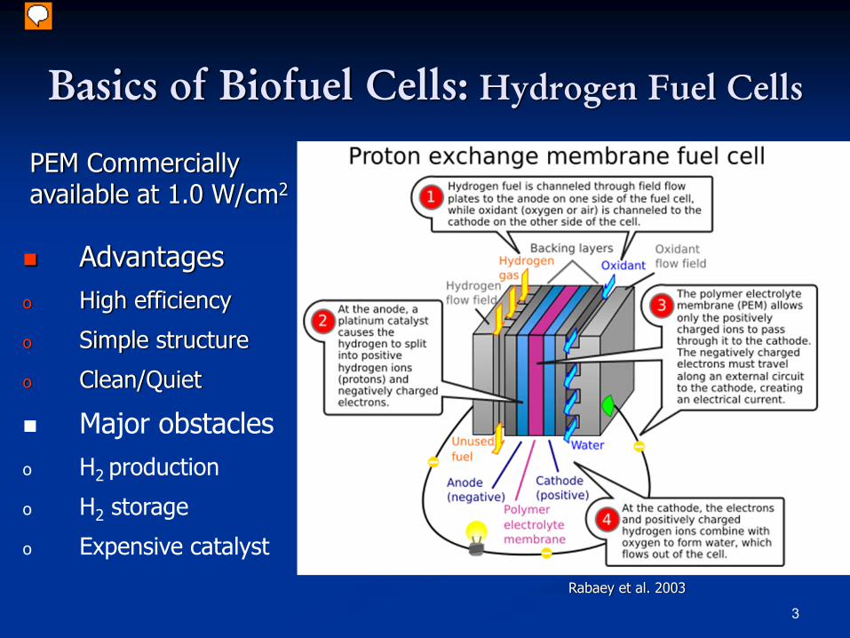
Basics of Biofuel Cells: Hydrogen Fuel Cells
PEM Commerciallyavailable at 1.0 W/cm2
Advantageso High efficiency
o Simple structure
o Clean/Quiet
Major obstacleso H2 production
o H2 storage
o Expensive catalyst
Rabaey et al. 2003
4
Basics of Biofuel Cells: Introduction
Why Biofuel Cells
Fuel: renewable carbohydrates, such as sugars and alcohols, even waste water
Catalysts: microorganisms or enzymes, renewable
Milder operation temperature and neutral pH
Biofuel cells use biocatalysts for the conversion of chemical energy to electrical energy
5
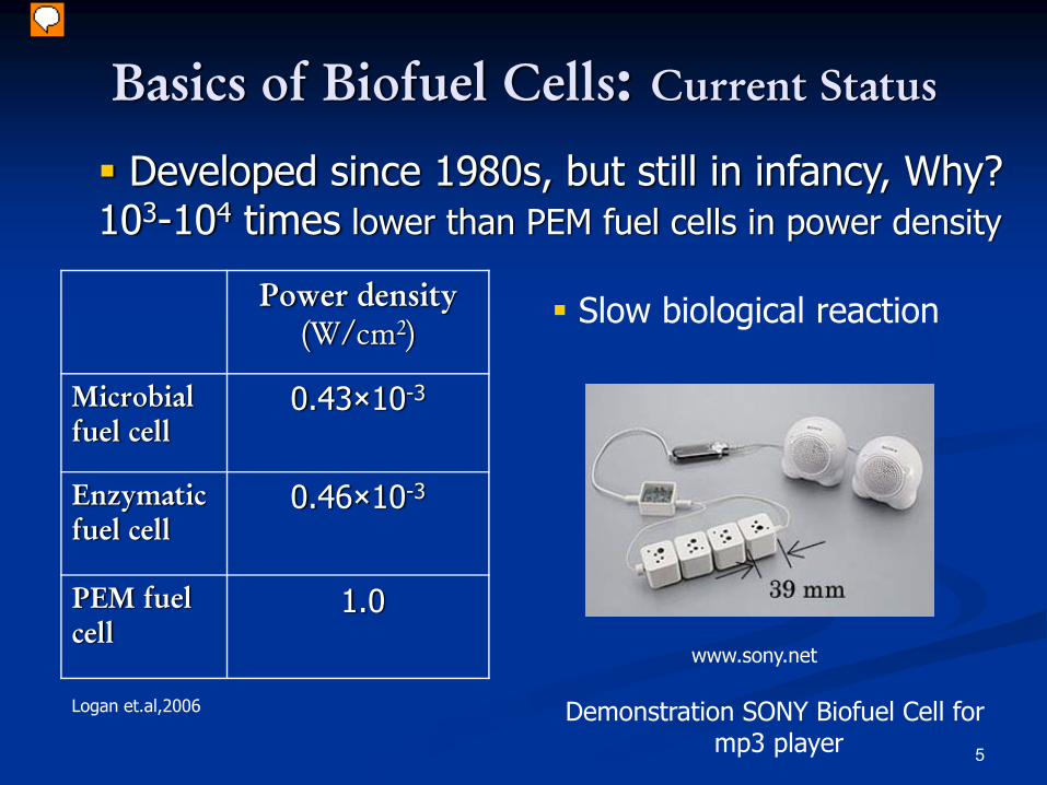
Power density(W/cm2)
Microbial fuel cell
0.43×10⁻³
Enzymatic fuel cell
0.46×10⁻³
PEM fuel cell
1.0
Developed since 1980s, but still in infancy, Why?103-104 times lower than PEM fuel cells in power density
Logan et.al,2006
Basics of Biofuel Cells: Current Status
Slow biological reaction
Demonstration SONY Biofuel Cell formp3 player
www.sony.net
6
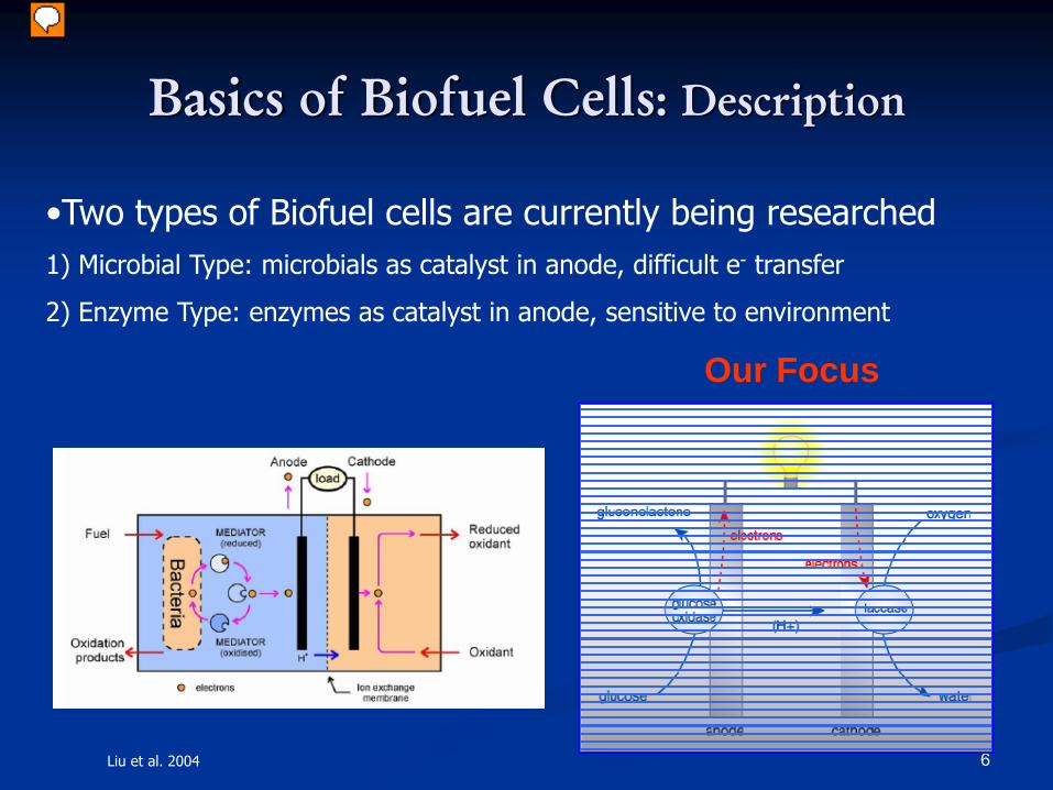
Basics of Biofuel Cells: Description
•Two types of Biofuel cells are currently being researched1) Microbial Type: microbials as catalyst in anode, difficult e- transfer
2) Enzyme Type: enzymes as catalyst in anode, sensitive to environment
Our Focus
Liu et al. 2004
7
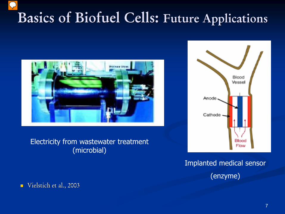
Basics of Biofuel Cells: Future Applications
Electricity from wastewater treatment (microbial)
Implanted medical sensor
(enzyme)Vielstich et al., 2003
8
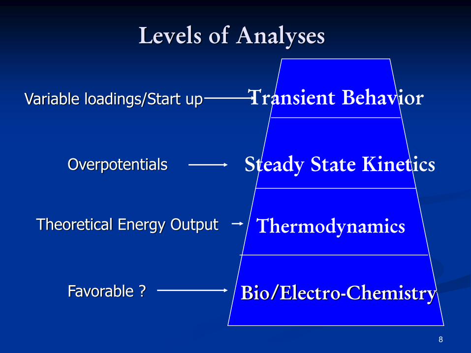
Levels of Analyses
Variable loadings/Start up Transient Behavior
Overpotentials Steady State Kinetics
Theoretical Energy Output Thermodynamics
Favorable ? Bio/Electro-Chemistry
9
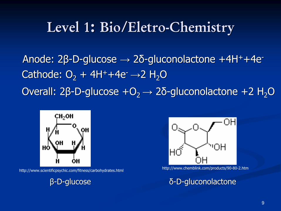
Level 1: Bio/Eletro-Chemistry
Anode: 2β-D-glucose → 2δ-gluconolactone +4H++4e-
Cathode: O2 + 4H++4e- →2 H2O
Overall: 2β-D-glucose +O2 → 2δ-gluconolactone +2 H2O
β-D-glucose δ-D-gluconolactone
http://www.chemblink.com/products/90-80-2.htmhttp://www.scientificpsychic.com/fitness/carbohydrates.html
1010
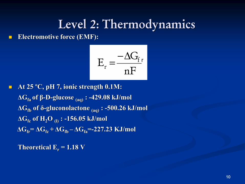
Level 2: ThermodynamicsElectromotive force (EMF):
At 25 ºC, pH 7, ionic strength 0.1M:ΔGfa of β-D-glucose (aq) : -429.08 kJ/molΔGfb of δ-gluconolactone (aq) : -500.26 kJ/molΔGfc of H2O (l) : -156.05 kJ/molΔGfr= ΔGfc +ΔGfb –ΔGfa=-227.23 KJ/mol
Theoretical Er = 1.18 V
nFG
E fr
Δ−= r
11
ηact
ηohm
ηconc
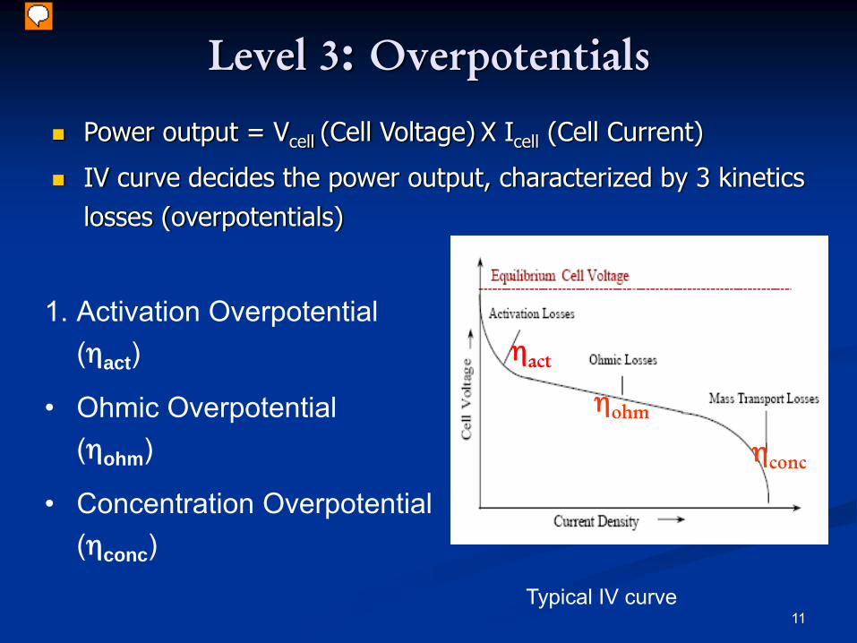
Typical IV curve
Power output = Vcell (Cell Voltage) X Icell (Cell Current)
IV curve decides the power output, characterized by 3 kinetics losses (overpotentials)
1. Activation Overpotential (ηact)
• Ohmic Overpotential (ηohm)
• Concentration Overpotential (ηconc)
Level 3: Overpotentials
12
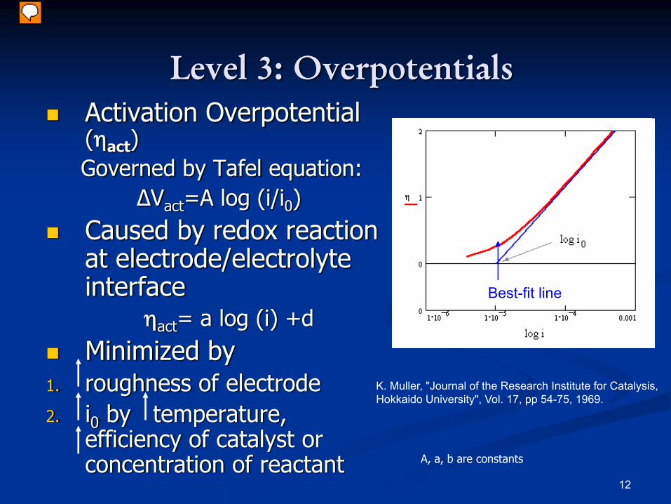
Level 3: OverpotentialsActivation Overpotential(ηact)Governed by Tafel equation:
ΔVact=A log (i/i0)Caused by redox reaction at electrode/electrolyte interface
ηact= a log (i) +dMinimized by
1. roughness of electrode2. i0 by temperature,
efficiency of catalyst or concentration of reactant
K. Muller, "Journal of the Research Institute for Catalysis, Hokkaido University", Vol. 17, pp 54-75, 1969.
Real Curve
Best-fit line
A, a, b are constants
13
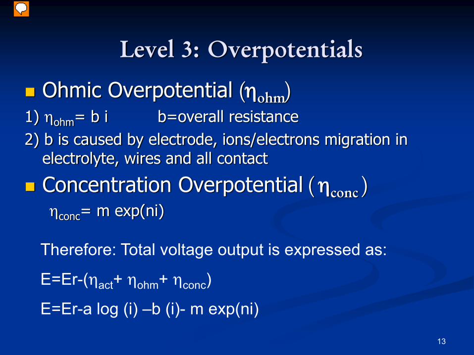
Ohmic Overpotential (ηohm)1) ηohm= b i b=overall resistance2) b is caused by electrode, ions/electrons migration in
electrolyte, wires and all contact
Concentration Overpotential ( ηconc )ηconc= m exp(ni)
Therefore: Total voltage output is expressed as:
E=Er-(ηact+ ηohm+ ηconc)
E=Er-a log (i) –b (i)- m exp(ni)
Level 3: Overpotentials
14
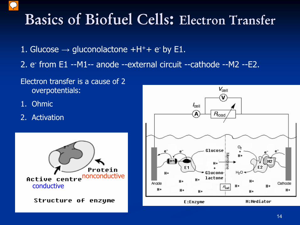
1. Glucose → gluconolactone +H++ e- by E1.
2. e- from E1 --M1-- anode --external circuit --cathode --M2 --E2.
conductivenonconductive
Basics of Biofuel Cells: Electron Transfer
Electron transfer is a cause of 2 overpotentials:
1. Ohmic
2. Activation
15
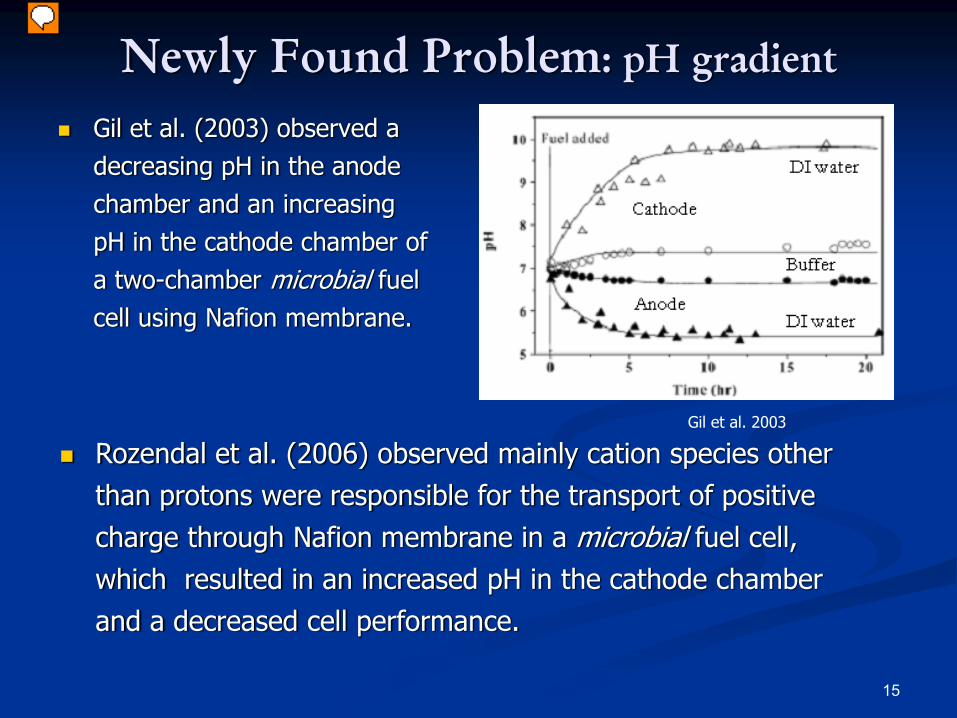
Newly Found Problem: pH gradient
Gil et al. (2003) observed a decreasing pH in the anode chamber and an increasing pH in the cathode chamber of a two-chamber microbial fuel cell using Nafion membrane.
Rozendal et al. (2006) observed mainly cation species other than protons were responsible for the transport of positive charge through Nafion membrane in a microbial fuel cell, which resulted in an increased pH in the cathode chamber and a decreased cell performance.
Gil et al. 2003
16
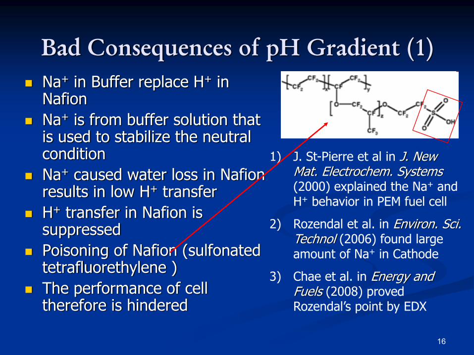
Bad Consequences of pH Gradient (1)Na+ in Buffer replace H+ in NafionNa+ is from buffer solution that is used to stabilize the neutral condition Na+ caused water loss in Nafion results in low H+ transferH+ transfer in Nafion is suppressedPoisoning of Nafion (sulfonated tetrafluorethylene )The performance of cell therefore is hindered
1) J. St-Pierre et al in J. New Mat. Electrochem. Systems(2000) explained the Na+ and H+ behavior in PEM fuel cell
2) Rozendal et al. in Environ. Sci. Technol (2006) found large amount of Na+ in Cathode
3) Chae et al. in Energy and Fuels (2008) proved Rozendal’s point by EDX
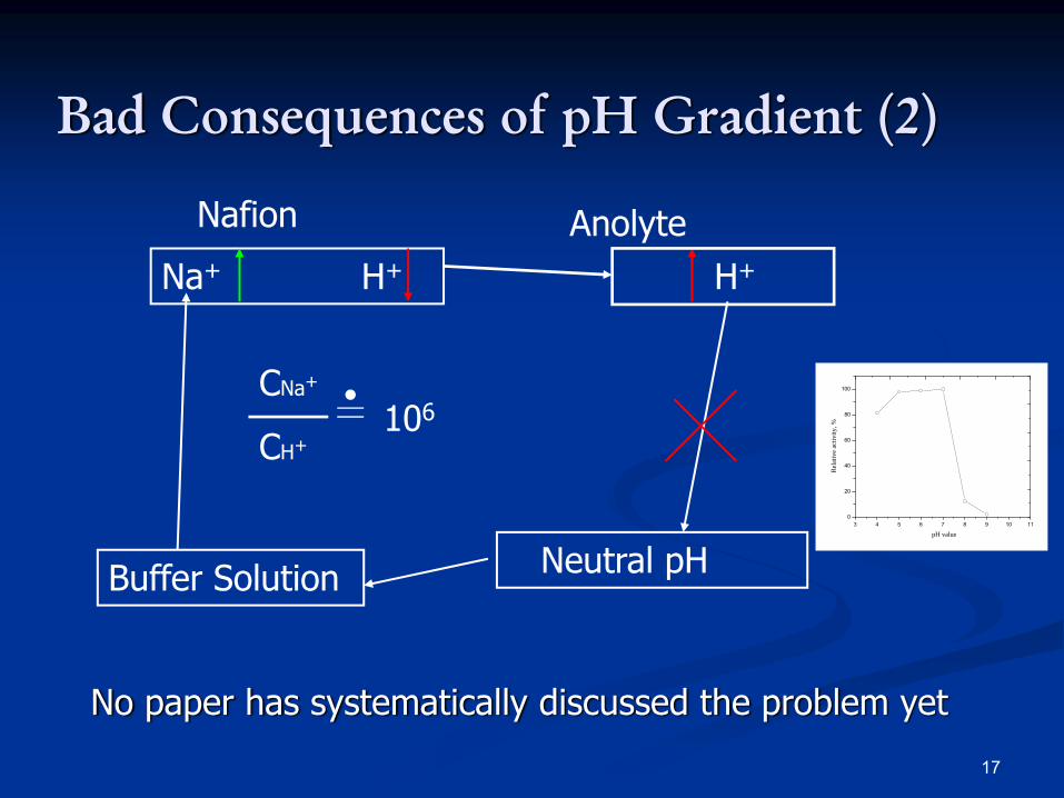
17
Neutral pHBuffer Solution
Na+ H+
Nafion
H+
Anolyte
CNa+
CH+106
Bad Consequences of pH Gradient (2)
No paper has systematically discussed the problem yet
3 4 5 6 7 8 9 10 110
20
40
60
80
100
Rela
tive
activ
ity, %
pH value
18
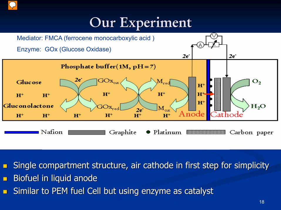
Our ExperimentMediator: FMCA (ferrocene monocarboxylic acid )
Enzyme: GOx (Glucose Oxidase)
Single compartment structure, air cathode in first step for simplicityBiofuel in liquid anodeSimilar to PEM fuel Cell but using enzyme as catalyst
19
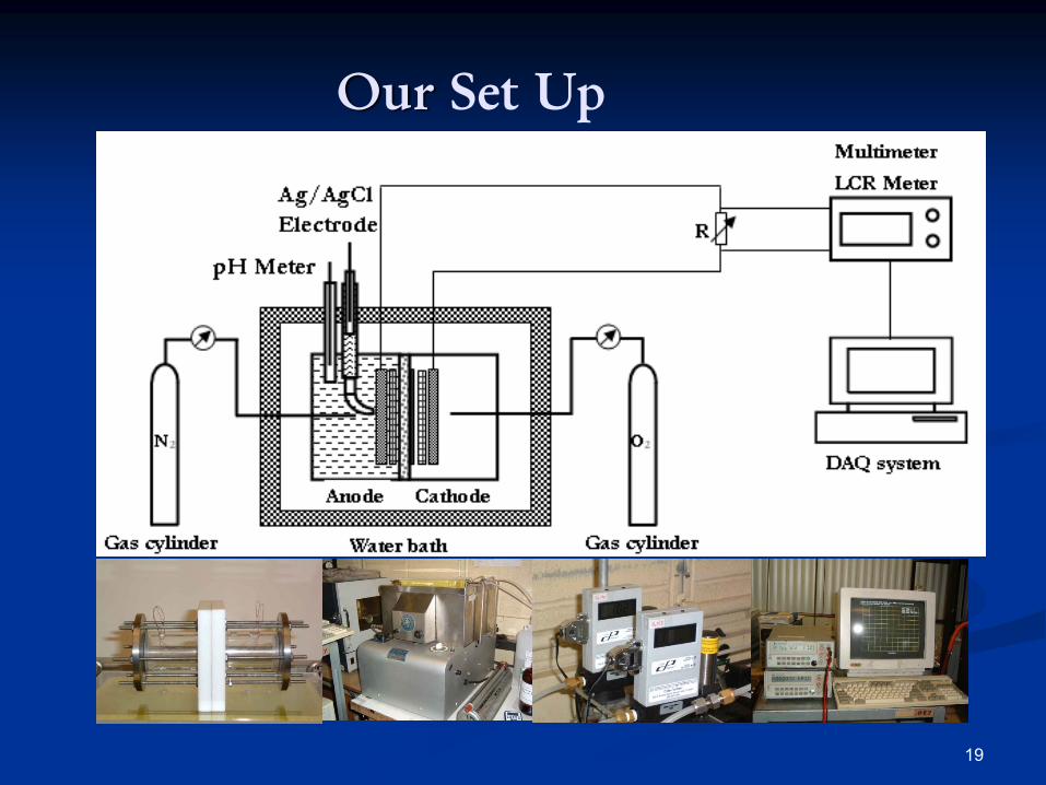
Our Set Up
20
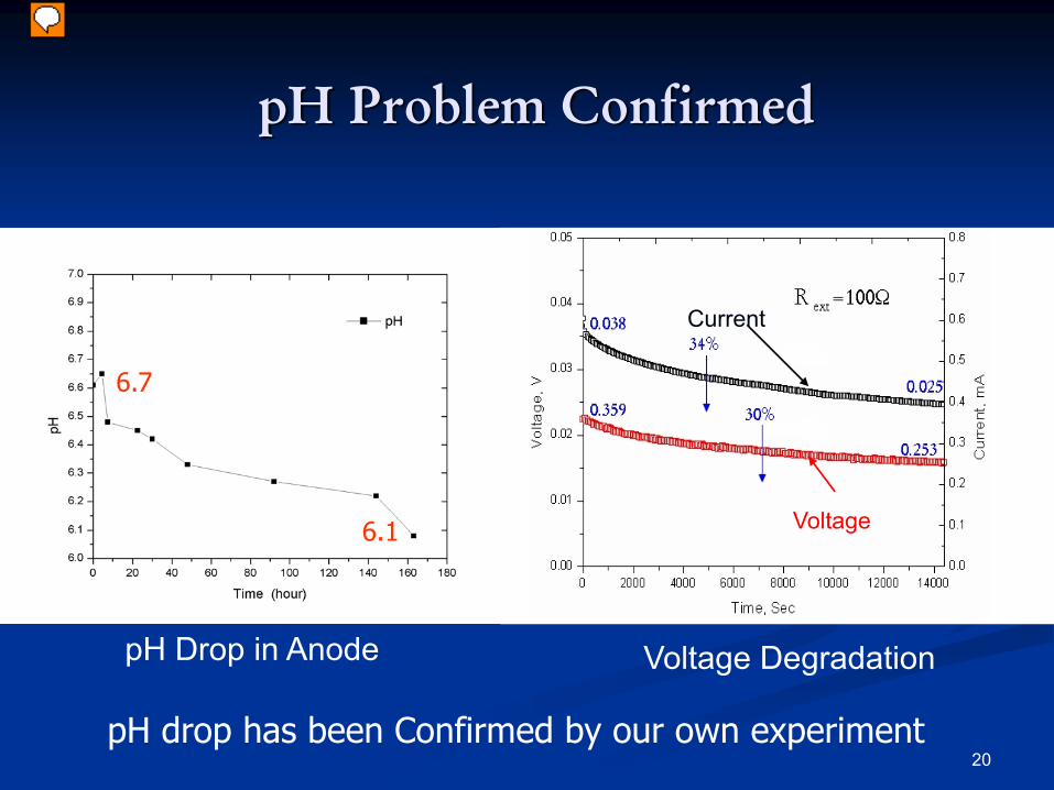
pH Drop in Anode Voltage Degradation
pH Problem Confirmed
Current
Voltage
pH drop has been Confirmed by our own experiment
6.7
6.1
21
Proposed Solutions
1. Other cation membranes with H+ selectivity
2. Membraneless Structure
3. Using a buffer that contains no Na+
4. Anion Exchange Membranes (AEM)
22
Possibility 1 : Selective Membranes
Unfortunately, such membrane has not been invented or discovered so far
Such ideal membrane remains as a challenge to biochemists
23
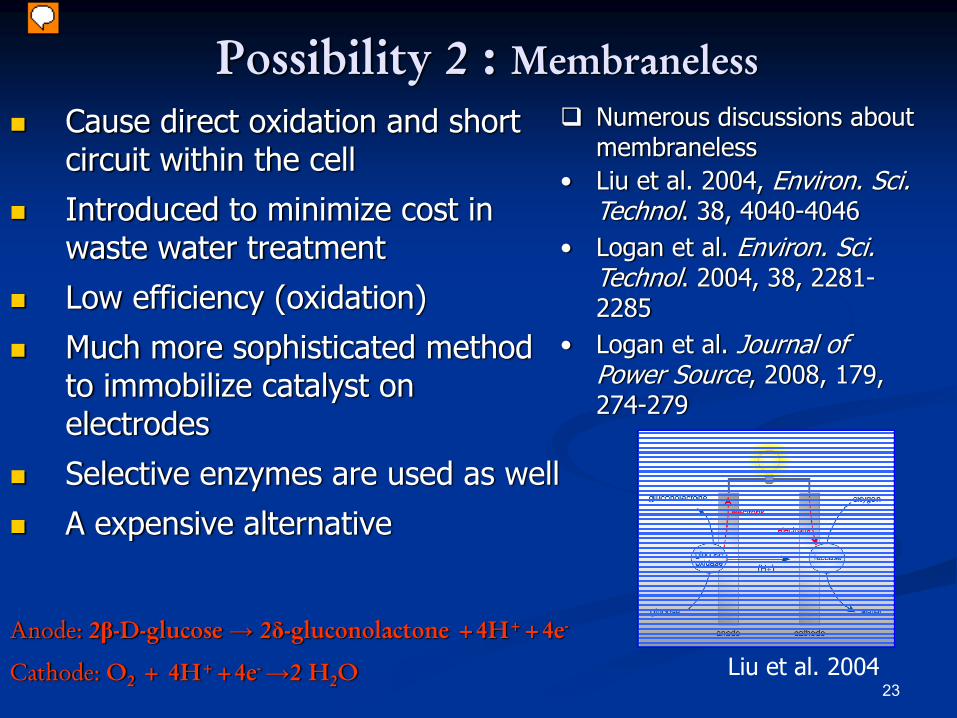
Possibility 2 : MembranelessCause direct oxidation and short circuit within the cell
Introduced to minimize cost in waste water treatment
Low efficiency (oxidation)
Much more sophisticated method to immobilize catalyst on electrodes
Selective enzymes are used as well
A expensive alternative
Anode: 2β-D-glucose → 2δ-gluconolactone +4H++4e-
Cathode: O2 + 4H++4e- →2 H2O
Numerous discussions about membraneless
• Liu et al. 2004, Environ. Sci. Technol. 38, 4040-4046
• Logan et al. Environ. Sci. Technol. 2004, 38, 2281-2285
• Logan et al. Journal of Power Source, 2008, 179, 274-279
Liu et al. 2004
2424
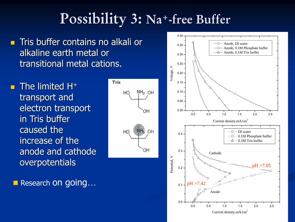
Possibility 3: Na+-free Buffer
0.0 0.5 1.0 1.5 2.0 2.50.00
0.05
0.10
0.15
0.20
0.25
0.30
0.35
0.40
Current density,mA/cm2
Vol
tage
, V
Anode, DI water Anode, 0.1M Phosphate buffer Anode, 0.1M Tris buffer
0.0 0.5 1.0 1.5 2.0 2.50.0
0.1
0.2
0.3
0.4
Anode
Cathode
Pote
ntia
l, V
Current density,mA/cm2
DI water 0.1M Phosphate buffer 0.1M Tris buffer
pH =7.05
pH =7.23
pH =4.45
pH =7.42
The limited H+
transport and electron transport in Tris buffer caused the increase of the anode and cathode overpotentials
Tris buffer contains no alkali or alkaline earth metal or transitional metal cations.
Research on going…
25
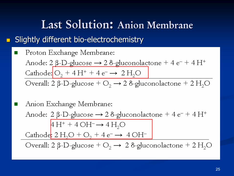
Last Solution: Anion MembraneSlightly different bio-electrochemistry
26
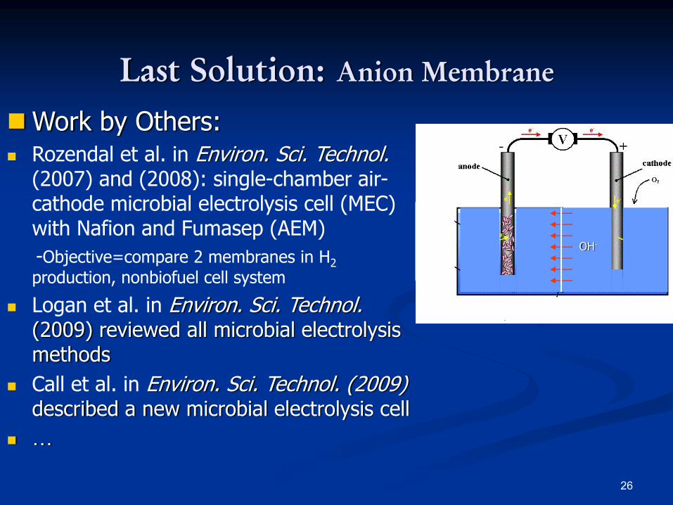
Last Solution: Anion Membrane
OH-
Work by Others:Rozendal et al. in Environ. Sci. Technol. (2007) and (2008): single-chamber air-cathode microbial electrolysis cell (MEC) with Nafion and Fumasep (AEM)-Objective=compare 2 membranes in H2production, nonbiofuel cell system
Logan et al. in Environ. Sci. Technol. (2009) reviewed all microbial electrolysis methodsCall et al. in Environ. Sci. Technol. (2009) described a new microbial electrolysis cell…
27
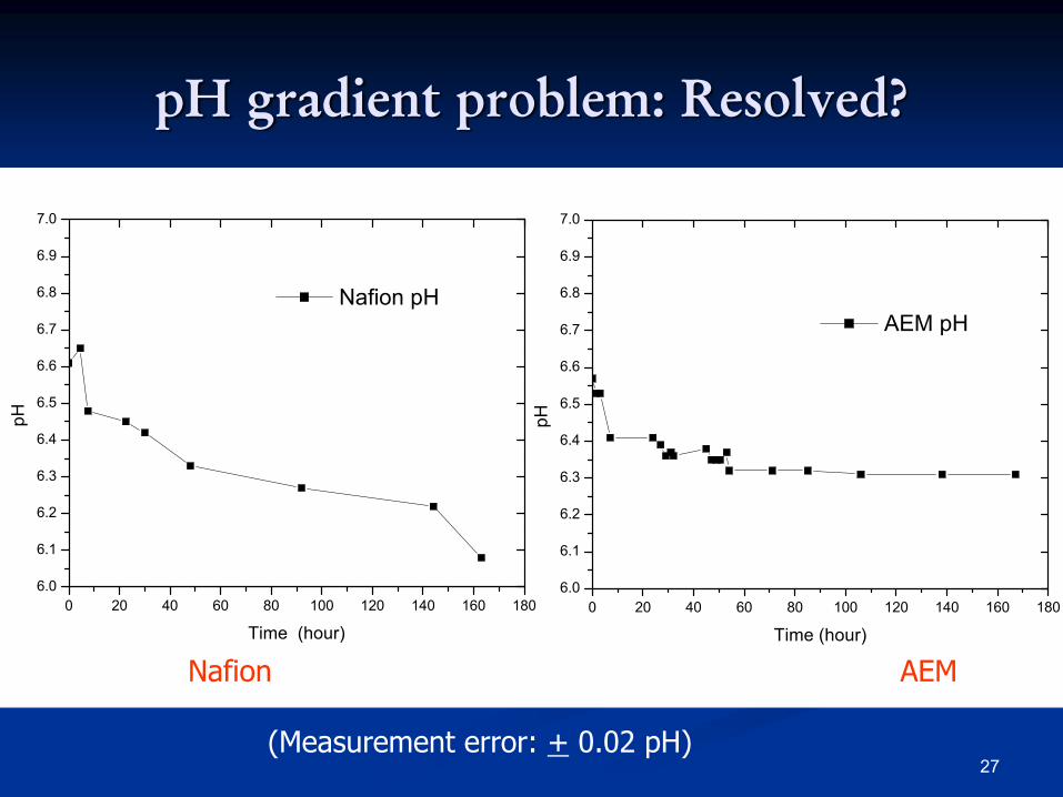
pH gradient problem: Resolved?
Nafion AEM
0 20 40 60 80 100 120 140 160 1806.0
6.1
6.2
6.3
6.4
6.5
6.6
6.7
6.8
6.9
7.0
Nafion pH
pH
Time (hour)0 20 40 60 80 100 120 140 160 180
6.0
6.1
6.2
6.3
6.4
6.5
6.6
6.7
6.8
6.9
7.0
AEM pH
pH
Time (hour)
(Measurement error: + 0.02 pH)
28
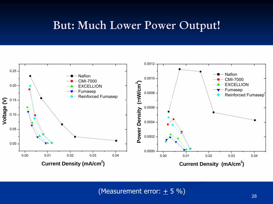
But: Much Lower Power Output!
0.00 0.01 0.02 0.03 0.04
0.00
0.05
0.10
0.15
0.20
0.25
Nafion CMI-7000 EXCELLION Fumasep Reinforced Fumasep
Volta
ge (V
)
Current Density (mA/cm2)0.00 0.01 0.02 0.03 0.04
0.0000
0.0002
0.0004
0.0006
0.0008
0.0010
0.0012
Nafion CMI-7000 EXCELLION Fumasep Reinforced Fumasep
Pow
er D
ensi
ty (
mW
/cm
2 )
Current Density (mA/cm2)
(Measurement error: + 0.02 pH)
(Measurement error: + 5 %)

29
Why AEM has a lower power?
Description Thickness (mm)
Resistance *(Ω)
Nafion Sulfonated tetrafluorethylene
0.2133 <0.034
Fumasep crosslinked polypropylene
substrate0.0355 <0.106
Fumasep (Reinforced)
0.0812 <0.245
CMI-7000 Gel polystyrene crosslinked with divinylbenzene
0.4622 <4.820
EXCELLION I-200 polypropylene binder from a
solventless method0.3530 0.803-1.606
* With effective electrode area of 6.24 cm2
30
Summary of Anion Membrane BFC
Higher resistance is one of the causes for its low power densityOther unknown causes are also possibleSeems to be a brighter way against the bottleneckTransient behavior of OH- in cathode is still not fully understood
31
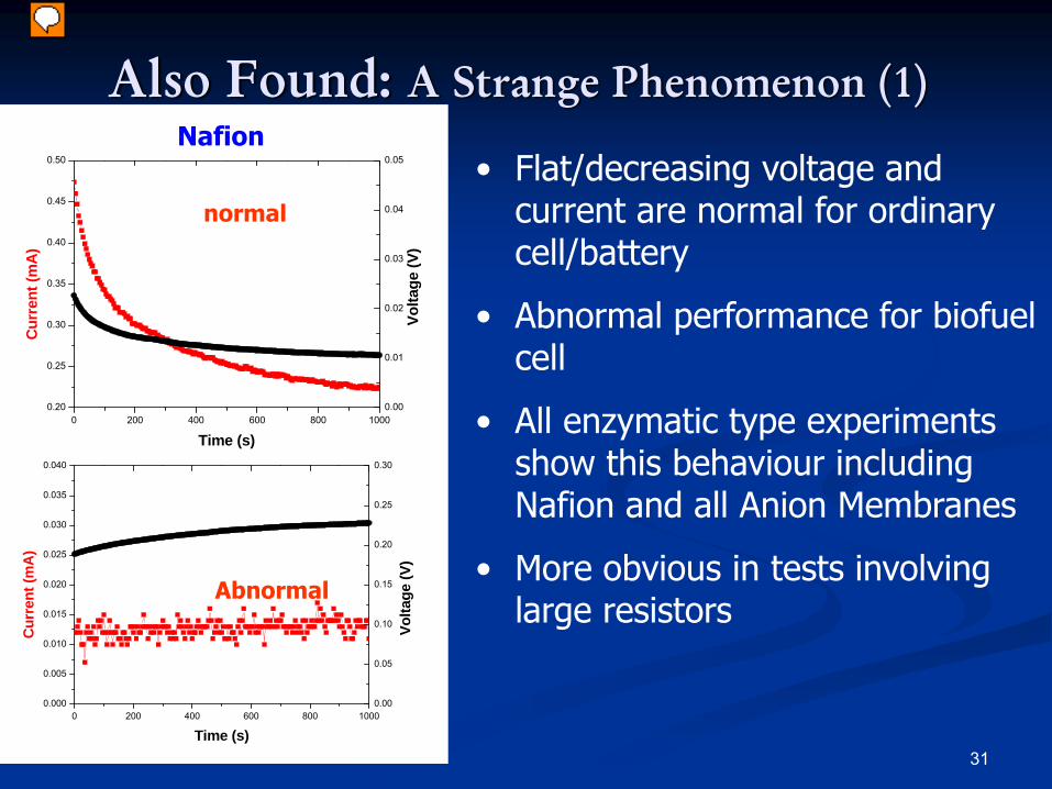
Also Found: A Strange Phenomenon (1)
• Flat/decreasing voltage and current are normal for ordinary cell/battery
• Abnormal performance for biofuel cell
• All enzymatic type experiments show this behaviour including Nafion and all Anion Membranes
• More obvious in tests involving large resistors
normal
Abnormal
0 200 400 600 800 10000.20
0.25
0.30
0.35
0.40
0.45
0.50
Volta
ge (V
)
Cur
rent
(mA
)
Time (s)
0.00
0.01
0.02
0.03
0.04
0.05
0 200 400 600 800 10000.000
0.005
0.010
0.015
0.020
0.025
0.030
0.035
0.040
Volta
ge (V
)
Cur
rent
(mA
)
Time (s)
0.00
0.05
0.10
0.15
0.20
0.25
0.30
Nafion
32
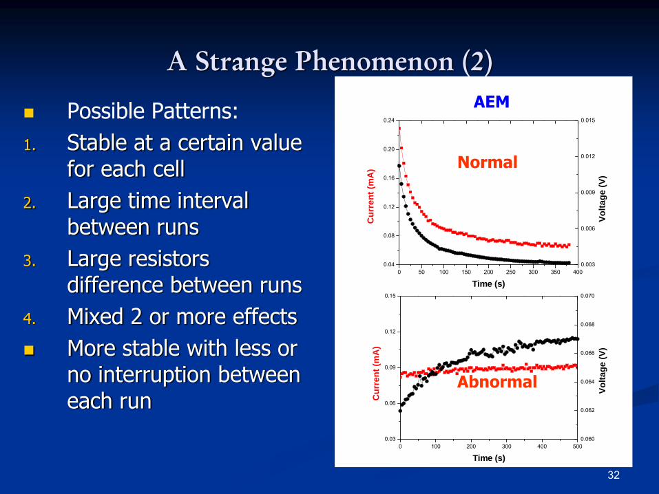
A Strange Phenomenon (2)
Possible Patterns:1. Stable at a certain value
for each cell2. Large time interval
between runs3. Large resistors
difference between runs4. Mixed 2 or more effects
More stable with less or no interruption between each run
0 100 200 300 400 5000.03
0.06
0.09
0.12
0.15
Volta
ge (V
)
Cur
rent
(mA
)
Time (s)
0.060
0.062
0.064
0.066
0.068
0.070
0 50 100 150 200 250 300 350 4000.04
0.08
0.12
0.16
0.20
0.24
Volta
ge (V
)
Cur
rent
(mA
)
Time (s)
0.003
0.006
0.009
0.012
0.015
Normal
Abnormal
AEM
33
www.phy-astr.gsu.edu
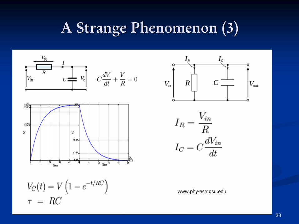
A Strange Phenomenon (3)
34
Reminds us of capacitanceProposed mechanism
1. Double layers on interface2. In parallel or in series?3. Charge accumulated on double layer in open
circuit4. Long time of charge/discharge in bio-involved
reaction
A Strange Phenomenon (3)
Other proposed mechanism???
35
Summary/Further Work
The pH problem caused by buffer is critical
No systematic analysis is available
Tris buffer method can be studied further by exploring similar buffer solution
AEM seems to be a possible solution, and should be studied further by comparing individual current/power behaviour
Further understanding of the strange phenomenon will contribute to transient behavior on the electrolyte/electrode interface

36
Thanks!
![Visual Analytics of Cascaded Bottlenecks in Planar Flow ...hamann/PostGillmannWis...works is the identification and elimination of bottlenecks [18]. The analysis of bottlenecks in](https://img.pdfslide.net/doc/110x75/6066a715e1fcfc51770dd091/visual-analytics-of-cascaded-bottlenecks-in-planar-flow-hamannpostgillmannwis.jpg)