Embed Size (px)
Citation preview

Pressure
WIKA data sheet PV 22.01
Page 1 of 12
Data sheets showing similar products:switchGAUGE, stainless steel version; models PGS23.1x0; see data sheet PV 22.02switchGAUGE, stainless steel safety version; model PGS23.063; see data sheet PV 22.03
Description
Wherever the process pressure has to be indicated locally and, at the same time, circuits need to be switched, the model PGS21.1x0 switchGAUGE finds its use.
Switch contacts (electrical alarm contacts) make or break circuits dependent upon the pointer position of the indicating measuring instrument. The switch contacts are adjustable over the full extent of the scale range (see DIN 16085), and are mounted predominantly below the dial, though also partly on top of the dial. The instrument pointer (actual value point-er) moves freely across the entire scale range, independent of the setting.The set pointer can be adjusted using a removable adjust-ment key in the window.
Switch contacts consisting of several contacts can also be set to a single set point. Contact actuation is made when the actual value pointer travels beyond or below the desired set point.
The pressure gauge is manufactured in accordance with DIN 16085 and fulfils all requirements of the relevant stand-ards (EN 837-1) and regulations for the on-site display of the working pressure of pressure vessels.
As switch contacts, magnetic snap-action contacts, reed switches, inductive contacts and electronic contacts are available. For triggering programmable logic controllers (PLC), electronic contacts and reed switches can be used.
Applications
■ Control and regulation of industrial processes ■ Monitoring of plants and switching of circuits ■ For gaseous and liquid media that are not highly viscous
or crystallising and will not attack copper alloy parts
Special features
■ High reliability and long service life ■ Up to 4 switch contacts per instrument ■ Instruments with electronic contacts for PLC applications ■ Contact gauges comply with DIN 16085
Bourdon tube pressure gauge with switch contactsStainless steel case, NS 100 and 160Models PGS21.100 and PGS21.160
Model PGS21.100 with model 821.21 switch contacts
WIKA data sheet PV 22.01 ∙ 03/2020
for further approvals see page 7
WIKA data sheet PV 22.01 ∙ 03/2020 Page 2 of 12
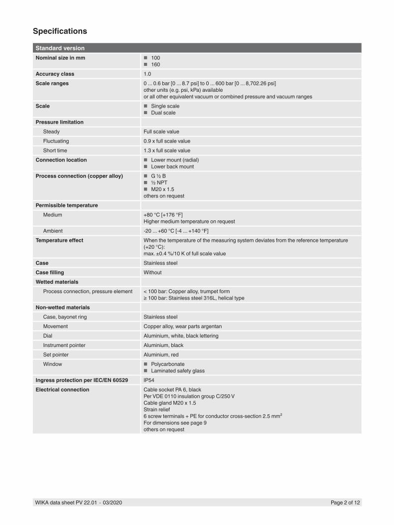
Specifications
Standard versionNominal size in mm ■ 100
■ 160Accuracy class 1.0Scale ranges 0 ... 0.6 bar [0 ... 8.7 psi] to 0 ... 600 bar [0 ... 8,702.26 psi]
other units (e.g. psi, kPa) availableor all other equivalent vacuum or combined pressure and vacuum ranges
Scale ■ Single scale ■ Dual scale
Pressure limitationSteady Full scale valueFluctuating 0.9 x full scale valueShort time 1.3 x full scale value
Connection location ■ Lower mount (radial) ■ Lower back mount
Process connection (copper alloy) ■ G ½ B ■ ½ NPT ■ M20 x 1.5
others on requestPermissible temperature
Medium +80 °C [+176 °F]Higher medium temperature on request
Ambient -20 ... +60 °C [-4 ... +140 °F]Temperature effect When the temperature of the measuring system deviates from the reference temperature
(+20 °C):max. ±0.4 %/10 K of full scale value
Case Stainless steelCase filling WithoutWetted materials
Process connection, pressure element < 100 bar: Copper alloy, trumpet form≥ 100 bar: Stainless steel 316L, helical type
Non-wetted materialsCase, bayonet ring Stainless steelMovement Copper alloy, wear parts argentanDial Aluminium, white, black letteringInstrument pointer Aluminium, blackSet pointer Aluminium, redWindow ■ Polycarbonate
■ Laminated safety glassIngress protection per IEC/EN 60529 IP54Electrical connection Cable socket PA 6, black
Per VDE 0110 insulation group C/250 VCable gland M20 x 1.5Strain relief6 screw terminals + PE for conductor cross-section 2.5 mm²For dimensions see page 9others on request
WIKA data sheet PV 22.01 ∙ 03/2020 Page 3 of 12
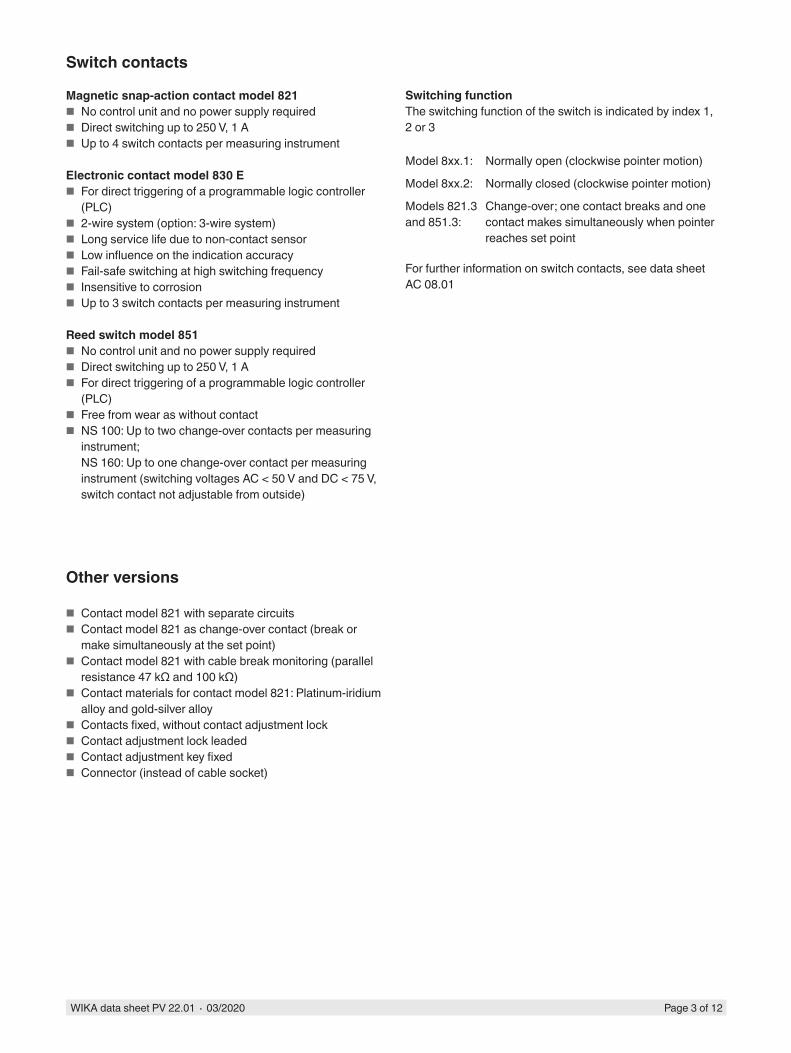
Switch contacts
Magnetic snap-action contact model 821 ■ No control unit and no power supply required ■ Direct switching up to 250 V, 1 A ■ Up to 4 switch contacts per measuring instrument
Electronic contact model 830 E ■ For direct triggering of a programmable logic controller
(PLC) ■ 2-wire system (option: 3-wire system) ■ Long service life due to non-contact sensor ■ Low influence on the indication accuracy ■ Fail-safe switching at high switching frequency ■ Insensitive to corrosion ■ Up to 3 switch contacts per measuring instrument
Reed switch model 851 ■ No control unit and no power supply required ■ Direct switching up to 250 V, 1 A ■ For direct triggering of a programmable logic controller
(PLC) ■ Free from wear as without contact ■ NS 100: Up to two change-over contacts per measuring
instrument;NS 160: Up to one change-over contact per measuring instrument (switching voltages AC < 50 V and DC < 75 V, switch contact not adjustable from outside)
Other versions
■ Contact model 821 with separate circuits ■ Contact model 821 as change-over contact (break or
make simultaneously at the set point) ■ Contact model 821 with cable break monitoring (parallel
resistance 47 kΩ and 100 kΩ) ■ Contact materials for contact model 821: Platinum-iridium
alloy and gold-silver alloy ■ Contacts fixed, without contact adjustment lock ■ Contact adjustment lock leaded ■ Contact adjustment key fixed ■ Connector (instead of cable socket)
Switching functionThe switching function of the switch is indicated by index 1, 2 or 3
Model 8xx.1: Normally open (clockwise pointer motion)
Model 8xx.2: Normally closed (clockwise pointer motion)
Models 821.3 and 851.3:
Change-over; one contact breaks and one contact makes simultaneously when pointer reaches set point
For further information on switch contacts, see data sheet AC 08.01

WIKA data sheet PV 22.01 ∙ 03/2020 Page 4 of 12
Specifications for instruments with magnetic snap-action contact model 821
Measuring span Nominal size Max. number of con-tacts
Switching current range I
Switch version 1)
≤ 1.0 bar 100, 160 1 0.02 ... 0.3 A L> 1.0 bar 100, 160 1 0.02 ... 0.6 A S≤ 1.6 bar 100, 160 2 0.02 ... 0.3 A L> 1.6 bar 100, 160 2 0.02 ... 0.6 A S≤ 4.0 bar 100 3 or 4 0.02 ... 0.3 A L> 4.0 bar 100 3 or 4 0.02 ... 0.6 A S≤ 2.5 bar 160 3 or 4 0.02 ... 0.3 A L> 2.5 bar 160 3 or 4 0.02 ... 0.6 A S
1) Design of the contact coil: Version “L” = light-weight, version “S” = heavy
The recommended setting range of the contacts is 25 ... 75 % of the scale (0 ... 100 % on request).Contact material (standard): Silver-nickel, gold-plated
Setting the contactsThe recommended minimum clearance between 2 contacts is 20 % of the measuring span.The switch hysteresis is 2 ... 5 % (typical).
Characteristics Unfilled instruments Filled instrumentsResistive load Resistive loadSwitch version “S” Switch version “L” Switch version “S” Switch version “L”
Rated operating voltage Ueff ≤ 250 V ≤ 250 VRated operating current
Switch-on currentSwitch-off currentContinuous current
≤ 1.0 A≤ 1.0 A≤ 0.6 A
≤ 0.5 A≤ 0.5 A≤ 0.3 A
≤ 1.0 A≤ 1.0 A≤ 0.6 A
≤ 0.5 A≤ 0.5 A≤ 0.3 A
Switching power ≤ 30 W / ≤ 50 VA ≤ 20 W / ≤ 20 VA
Recommended contact load with resistive and inductive loads
Operating voltage Unfilled instruments Filled instrumentsResistive load Inductive load Resistive load Inductive loadDirect current
Alter-nating current
cos ϕ > 0.7 Direct current
Alter-nating current
cos ϕ > 0.7
DC 220 V / AC 230 V 100 mA 120 mA 65 mA 65 mA 90 mA 40 mADC 110 V / AC 110 V 200 mA 240 mA 130 mA 130 mA 180 mA 85 mADC 48 V / AC 48 V 300 mA 450 mA 200 mA 190 mA 330 mA 130 mADC 24 V / AC 24 V 400 mA 600 mA 250 mA 250 mA 450 mA 150 mA
WIKA data sheet PV 22.01 ∙ 03/2020 Page 5 of 12
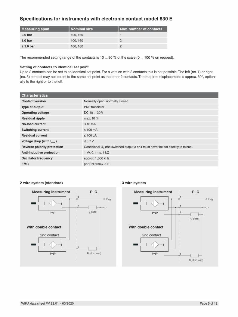
3-wire system
RL (2nd load)
RL (load)
2-wire system (standard)
With double contact
2nd contact
RL (2nd load)
RL (load)
With double contact
2nd contact
Measuring instrument PLC Measuring instrument PLC
+UB
-
PNP
PNP
4
1
2
+UB
-
PNP
PNP
2
1
3
4
Specifications for instruments with electronic contact model 830 E
Measuring span Nominal size Max. number of contacts0.6 bar 100, 160 11.0 bar 100, 160 2≥ 1.6 bar 100, 160 2
The recommended setting range of the contacts is 10 ... 90 % of the scale (0 ... 100 % on request).
Setting of contacts to identical set pointUp to 2 contacts can be set to an identical set point. For a version with 3 contacts this is not possible. The left (no. 1) or right (no. 3) contact may not be set to the same set point as the other 2 contacts. The required displacement is approx. 30°, option-ally to the right or to the left.
CharacteristicsContact version Normally open, normally closedType of output PNP transistorOperating voltage DC 10 ... 30 VResidual ripple max. 10 %No-load current ≤ 10 mASwitching current ≤ 100 mAResidual current ≤ 100 µAVoltage drop (with Imax.) ≤ 0.7 VReverse polarity protection Conditional UB (the switched output 3 or 4 must never be set directly to minus)Anti-inductive protection 1 kV, 0.1 ms, 1 kΩOscillator frequency approx. 1,000 kHzEMC per EN 60947-5-2

WIKA data sheet PV 22.01 ∙ 03/2020 Page 6 of 12
Specifications for instruments with reed switch model 851
Measuring span Nominal size Max. number of contacts≥ 1.0 bar 100, 160 1≥ 1.6 bar 100, 160 2
Switching power Pmax 60 W / 60 VASwitching current 1 A
CharacteristicsContact version Change-over contactType of contact BistableMax. switching voltage AC/DC 250 VMin. switching voltage Not requiredSwitching current AC/DC 1 AMin. switching current Not requiredTransport current AC/DC 2 Acos ϕ 1Switching power 60 W/ VAContact resistance (static) 100 mΩInsulation resistance 109 ΩBreakdown voltage DC 1,000 VSwitching time incl. contact chatter 4.5 msContact material RhodiumSwitch hysteresis 3 ... 5 %
■ The limit values presented here must not be exceeded. ■ When using two contacts, these cannot be set to the same point. Depending on the switching function, a minimum clear-
ance of 15 ... 30° is required. ■ The setting range of the contacts is 10 ... 90 % of the scale. ■ The switching function can be set in manufacturing such that the reed contact will actuate exactly at the required switch
point. For this, we need the switching direction to be specified on order.

WIKA data sheet PV 22.01 ∙ 03/2020 Page 7 of 12
Approvals
Logo Description CountryEU declaration of conformityPressure equipment directivePS > 200 bar, module A, pressure accessory
European Union
EAC (option) ■ EMC directive ■ Pressure equipment directive ■ Low voltage directive
Eurasian Economic Community
GOST (option)Metrology, measurement technology
Russia
KazInMetr (option)Metrology, measurement technology
Kazakhstan
- MTSCHS (option)Permission for commissioning
Kazakhstan
BelGIM (option)Metrology, measurement technology
Belarus
Uzstandard (option)Metrology, measurement technology
Uzbekistan
- CRNSafety (e.g. electr. safety, overpressure, ...)
Canada
Certificates (option)
■ 2.2 test report per EN 10204 (e.g. state-of-the-art manufacturing, indication accuracy)
■ 3.1 inspection certificate per EN 10204 (e.g. indication accuracy)
Approvals and certificates, see website
Accessories
■ Panel mounting flange, polished stainless steel ■ Surface mounting flange, stainless steel ■ Surface mounting lugs on the back, stainless steel ■ Sealings (model 910.17, see data sheet AC 09.08) ■ Valves (models IV20/IV21, see data sheet AC 09.19, and
models IV10/IV11, see data sheet AC 09.22)
■ Syphons (model 910.15, see data sheet AC 09.06) ■ Overpressure protector model 910.13, see data sheet
AC 09.04) ■ Cooling element (model 910.32, see data sheet AC 09.21) ■ Diaphragm seals
WIKA data sheet PV 22.01 ∙ 03/2020 Page 8 of 12
M20x1,5
68
M20x1,5
49.5
1406
2234
.01
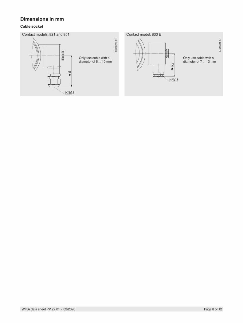
Contact models: 821 and 851
Only use cable with a diameter of 5 ... 10 mm
1433
6089
.01
Contact model: 830 E
Only use cable with a diameter of 7 ... 13 mm
Dimensions in mmCable socket
WIKA data sheet PV 22.01 ∙ 03/2020 Page 9 of 12
1144
3741
.01
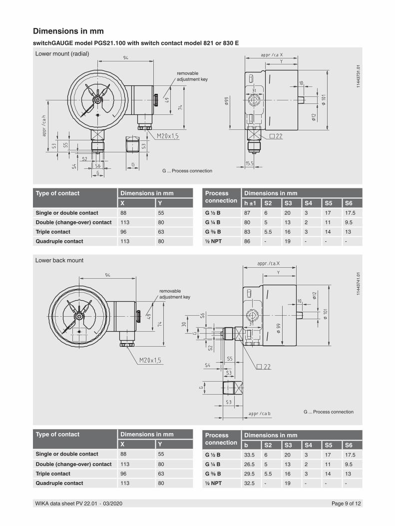
Lower back mount
Dimensions in mmswitchGAUGE model PGS21.100 with switch contact model 821 or 830 E
1144
3731
.01
Lower mount (radial)
Type of contact Dimensions in mmX Y
Single or double contact 88 55
Double (change-over) contact 113 80Triple contact 96 63Quadruple contact 113 80
Process connection
Dimensions in mmb S2 S3 S4 S5 S6
G ½ B 33.5 6 20 3 17 17.5G ¼ B 26.5 5 13 2 11 9.5G ⅜ B 29.5 5.5 16 3 14 13½ NPT 32.5 - 19 - - -
G ... Process connection
G ... Process connection
removable adjustment key
removable adjustment key
Process connection
Dimensions in mmh ±1 S2 S3 S4 S5 S6
G ½ B 87 6 20 3 17 17.5G ¼ B 80 5 13 2 11 9.5G ⅜ B 83 5.5 16 3 14 13½ NPT 86 - 19 - - -
Type of contact Dimensions in mmX Y
Single or double contact 88 55Double (change-over) contact 113 80Triple contact 96 63Quadruple contact 113 80

WIKA data sheet PV 22.01 ∙ 03/2020 Page 10 of 12
1144
4045
.01
Lower back mount
1144
3707
.01
Lower mount (radial)
Process connection
Dimensions in mmh ±1 S2 S3 S4 S5 S6
G ½ B 118 6 20 3 17 17.5G ¼ B 111 5 13 2 11 9.5G ⅜ B 114 5.5 16 3 14 13½ NPT 117 - 19 - - -
Type of contact Dimensions in mmX Y
Single or double contact 88 55Triple contact 96 63Quadruple contact 113 80
Process connection
Dimensions in mmb S2 S3 S4 S5 S6
G ½ B 33.5 6 20 3 17 17.5G ¼ B 26.5 5 13 2 11 9.5G ⅜ B 29.5 5.5 16 3 14 13½ NPT 32.5 - 19 - - -
Type of contact Dimensions in mmX
Single or double contact 105Triple contact 105Quadruple contact 119
switchGAUGE model PGS21.160 with switch contact model 821 or 830 E
G ... Process connection
G ... Process connection
removable adjustment key
removable adjustment key

WIKA data sheet PV 22.01 ∙ 03/2020 Page 11 of 12
Process connection
Dimensions in mmh ±1 S2 S3 S4 S5 S6
G ½ B 87 6 20 3 17 17.5G ¼ B 80 5 13 2 11 9.5G ⅜ B 83 5.5 16 3 14 13½ NPT 86 - 19 - - -
1403
4435
.01
Lower back mount
switchGAUGE model PGS21.100 with switch contact model 851.3 or 851.33
1402
1746
.01
Lower mount (radial)
Process connection
Dimensions in mmh ±1 S2 S3 S4 S5 S6
G ½ B 103 6 20 3 17 17.5G ¼ B 96 5 13 2 11 9.5G ⅜ B 99 5.5 16 3 14 13½ NPT 102 - 19 - - -
G ... Process connection
G ... Process connection
removable adjustment key
removable adjustment key

WIKA data sheet PV 22.01 ∙ 03/2020 Page 12 of 12
© 02/2009 WIKA Alexander Wiegand SE & Co. KG, all rights reserved.The specifications given in this document represent the state of engineering at the time of publishing.We reserve the right to make modifications to the specifications and materials.
03/2
020
EN
WIKA Alexander Wiegand SE & Co. KGAlexander-Wiegand-Straße 3063911 Klingenberg/GermanyTel. +49 9372 132-0Fax +49 9372 [email protected]
Ordering informationModel / Nominal size / Type of contact and switching function / Scale range / Process connection / Connection location / Options
Lower mount (radial)
Process connection
Dimensions in mmh ±1 S2 S3 S4 S5 S6
G ½ B 118 6 20 3 17 17.5G ¼ B 111 5 13 2 11 9.5G ⅜ B 114 5.5 16 3 14 13½ NPT 117 - 19 - - -
switchGAUGE model PGS21.160 with switch contact model 851.3 or 851.33
G ... Process connection 1402
1895
.01
removable adjustment key