Embed Size (px)
Citation preview
Brackish Resources Aquifer Characterization System Database Data DictionaryOpen File Report 12-02, Fourth Edition
April 2019
John E. Meyer, P.G.
i
Texas Water Development Board Open File Report 12-02, Fourth Edition Brackish Resources Aquifer Characterization System Database Data Dictionary By John E. Meyer, P.G.
April 2019
ii
Cover photo courtesy Nicole Meyer “Palo Duro State Park, Texas” The Triassic Tecovas Formation of the Dockum Group overlies the Permian Quatermaster Formation.

iii
Texas Water Development Board Peter M. Lake Chairman Kathleen Jackson Member Brooke T. Paup Member To provide leadership, information, education, and support for planning, financial assistance, and outreach for the conservation and responsible development of water for Texas. The Texas Water Development Board freely grants permission to copy and distribute its materials. The agency would appreciate acknowledgment.
Published and distributed by the Texas Water Development Board P.O. Box 13231, Capitol Station Austin, Texas 78711-3231 April 2019

iv
This page is intentionally blank.
v
Table of Contents 1. Introduction .............................................................................................................................. 1 2. Well location: tblWell_Location ............................................................................................. 4 3. Foreign keys: tblBracs_ForeignKey ...................................................................................... 10 4. Well geology: tblWell_Geology ............................................................................................ 12 5. Aquifer hydraulic properties: tblBracs_AquiferTestInformation .......................................... 17 6. Geophysical well log, header: tblGeophysicalLog_Header .................................................. 21 7. Geophysical well log, log runs: tblGeophysicalLog_Header_LogRuns ............................... 25 8. Geophysical well log, tool suite: tblGeophysicalLog_Suite.................................................. 28 9. Geophysical well log, water quality: tblGeophysicalLog_WQ ............................................. 29 10. Geophysical well log, water quality method: tblGeophysicalLog_WQ_Method ................. 31 11. Digital water well reports: tblBracsWaterWellReports ......................................................... 35 12. Static water level: tblBracs_SWL .......................................................................................... 37 13. Well construction: tblBracs_Casing ...................................................................................... 39 14. Water quality: tblBracsWaterQuality .................................................................................... 40 15. Water quality, infrequent constituents: tblBracsInfrequentConstituents ............................... 44 16. Geophysical well log, porosity: tblGeophysicalLog_Porosity .............................................. 46 17. Geophysical well log, Ro - TDS Method: tblBRACS_GL_Analysis_Ro_TDS_Main ......... 51 18. Geophysical well log, Ro sands: tblBRACS_GL_Analysis_Ro_Sands ................................ 53 19. Geophysical well log, TDS well: tblBRACS_GL_Analysis_TDS_Well .............................. 55 20. References .............................................................................................................................. 57 21. Appendix A: Pecos Valley Alluvium .................................................................................... 59
21.1 Aquifer determination: tblAquiferDetermination_PecosValley ................................. 59 21.2 Stratigraphic table for GIS import: gBRACS_ST ...................................................... 65 21.3 Master water quality: tblBracs_PV_MasterWaterQuality .......................................... 69 21.4 Net sand: tblWell_Geology_NetSand ........................................................................ 74 21.5 Net sand: tblWell_Geology_ProcessingNetSand_Temp ............................................ 76
22. Appendix B: Gulf Coast Aquifer in the Corpus Christi ASRCD .......................................... 79 22.1 Aquifer determination: tblAquiferDetermination_GulfCoast_ccasr .......................... 79 22.2 Stratigraphic table for GIS import: gBRACS_ST_GC............................................... 85 22.3 Master water quality: tblBracs_GC_MasterWaterQuality_ccasr ............................... 90 22.4 Net sand: tblWell_Geology_NetSand_GulfCoast_ccasr ............................................ 95 22.5 Net sand: tblWell_Geology_NetSand_GulfCoast_Temp_ccasr .............................. 101
23. Appendix C: Lower Rio Grande Valley Gulf Coast Aquifer BRACS Study ...................... 106 23.1 Aquifer determination: tblAquiferDetermination_GulfCoast .................................. 106 23.2 Master water quality: tblBracs_GC_MasterWaterQuality ....................................... 112 23.3 Net sand: tblWell_Geology_NetSand_GulfCoast .................................................... 118 23.4 Net sand: tblWell_Geology_NetSand_GulfCoast_Temp ......................................... 124
24. Appendix D: Queen City - Sparta Aquifer .......................................................................... 129 24.1 Aquifer determination: tblAquiferDetermination_PaleoceneEocene_sTx_QcSp .... 129 24.2 Stratigraphic table for GIS import: gBRACS_ST_SpQc ......................................... 136 24.3 Master water quality: tblBracs_QcSp_MasterWaterQuality .................................... 141 24.4 Net sand: tblWell_Geology_NetSand_QcSp............................................................ 146 24.5 Net sand: tblWell_Geology_NetSand_QcSp_Temp ................................................ 151
25. Appendix E: Wilcox, Carrizo, Queen City, Sparta, and Yegua Aquifers ........................... 156 25.1 Aquifer determination: tblAquiferDetermination_PaleoceneEocene_sTx ............... 156
vi
25.2 Stratigraphic table for GIS import: gBRACS_ST_PE_sTx ..................................... 164 25.3 Master water quality: tblBracs_PE_sTx_MasterWaterQuality ................................ 169 25.4 Net sand: tblWell_Geology_NetSand_PaleoceneEocene_sTx ................................ 176 25.5 Net sand: tblWell_Geology_NetSand_PaleoceneEocene_sTx_Temp ..................... 185 25.6 Net sand: tblWell_Geology_NetSand_PaleoceneEocene_sTx_Well_Decisions ..... 190
26. Appendix F: Lipan Aquifer ................................................................................................. 192 26.1 Aquifer determination: tblBracs_Lipan_AquiferDetermination .............................. 192 26.2 Master water quality: tblBracs_ Lipan_MasterWaterQuality .................................. 198 26.3 Lipan static water level: tblBracs_ Lipan_SWL ....................................................... 201 26.4 Lipan aquifer hydraulic properties: tblBracs_ Lipan_Aquifer_Test ........................ 203
27. Appendix G: Blossom Aquifer ............................................................................................ 208 27.1 Aquifer determination: tblAquiferDetermination_Kb .............................................. 208 27.2 Stratigraphic table for GIS import: gBRACS_ST_Kb.............................................. 213 27.3 Master water quality: tblBracs_MasterWaterQuality_Kb ........................................ 216 27.4 Net sand: tblWell_Geology_NetSand_Kb ................................................................ 223 27.5 Net sand: tblWell_Geology_NetSand_Kb_Temp .................................................... 225 27.6 Net sand: tblWell_Geology_NetSand_Kb_Well_Decisions .................................... 228
28. Appendix H: Nacatoch Aquifer ........................................................................................... 229 28.1 Aquifer determination: tblAquiferDetermination_Kn .............................................. 229 28.2 Stratigraphic table for GIS import: gBRACS_ST_Kn.............................................. 234 28.3 Master water quality: tblBracs_MasterWaterQuality_Kn ........................................ 237 28.4 Net sand: tblWell_Geology_NetSand_Kn ................................................................ 244 28.5 Net sand: tblWell_Geology_NetSand_Kn_Temp .................................................... 246 28.6 Net sand: tblWell_Geology_NetSand_Kn_Well_Decisions .................................... 249
29. Appendix I: Northern Trinity Aquifer ................................................................................. 250 29.1 Aquifer determination: tblBRACS_N_Trinity_AquiferDetermination .................... 250
vii
List of Figures Figure 1-1. BRACS Database table relationships...................................................................... 3 Figure 21.1-1. Regions within the Pecos Valley Alluvium Project area ...................................... 61
List of Tables Figure 1-1. BRACS Database table relationships...................................................................... 3 Table 2-1. Table tblWell_Location .......................................................................................... 4 Table 2-2. Lookup table tblLkSourceWellData ....................................................................... 5 Table 2-3. Lookup table tblLkHorizontalDatum. ..................................................................... 7 Table 2-4. Lookup table tblLkLocationMethod. ...................................................................... 7 Table 2-5. Lookup table tblLkAgency ..................................................................................... 8 Table 2-6. Lookup table tblLkVerticalDatum .......................................................................... 9 Table 2-7. Lookup table tblLkElevationMethod ...................................................................... 9 Table 3-1. Table tblBracs_ForeignKey. ................................................................................. 10 Table 3-2. Lookup table tblLkFK_ID_Name ......................................................................... 11 Table 4-1. Table tblWell_Geology ......................................................................................... 12 Table 4-2. Lookup table tblLkGeologicPick .......................................................................... 13 Table 4-3 Lookup table tblLkTDS_Range ............................................................................ 14 Table 4-4. Lookup table tblLkFaultType ............................................................................... 15 Table 4-5. Lookup table tblLkSourceGeologicData .............................................................. 16 Table 5-1. Table tblBRACS_AquiferTestInformation ........................................................... 17 Table 5-2. Lookup table tblLkUnitsOfMeasurement ............................................................. 18 Table 5-3. Lookup table tblLkWellYieldMethod ................................................................... 19 Table 6-1. Table tblGeophysicalLog_Header ........................................................................ 21 Table 6-2. Lookup table tblLkGlFileType ............................................................................. 22 Table 7-1. Table tblGeophysicalLog_Header_LogRuns ........................................................ 25 Table 7-2. Lookup table tblLkTbh_Corr_Method ................................................................. 27 Table 8-1. Table tblGeophysicalLog_Suite............................................................................ 28 Table 9-1. Table tblGeophysicalLog_WQ ............................................................................. 29 Table 9-2. Lookup table tblLkCon_Tds_Method................................................................... 30 Table 10-1. Table tblGeophysicalLog_WQ_Method ............................................................... 31 Table 10-2. Lookup table tblLkTdsMethod ............................................................................. 32 Table 10-3. Lookup table tblLkCf_Ro_MeanRoMethod ......................................................... 32 Table 10-4. Lookup table tblLkCf_Rxo_Ro_InvasionZone .................................................... 33 Table 10-5. Lookup table tblLkRwe_Rw_Cor ......................................................................... 33 Table 11-1. Table tblBracsWaterWellReports ......................................................................... 35 Table 12-1. Table tblBracs_SWL field names ......................................................................... 37 Table 12-2. Lookup table tblLkWaterLevelMethod. ............................................................... 38 Table 13-1. Table tblBracs_Casing. ......................................................................................... 39 Table 14-1. Table tblBracsWaterQuality ................................................................................. 40 Table 15-1. Table tblBracsInfrequentConstituents .................................................................. 44 Table 16-1. Table tblGeophysicalLog_Porosity ...................................................................... 46 Table 17-1. Table tblBRACS_GL_Analysis_Ro_TDS_Main ................................................. 51 Table 18-1. Table tblBracs_GL_Analysis_Ro_Sands.............................................................. 53 Table 19-1. Table tblBRACS_GL_Analysis_TDS_Well ........................................................ 55
viii
Table 21.1-1. Table tblAquiferDetermination_PecosValley ....................................................... 59 Table 21.1-2. Stratigraphic sequence of geologic formations within each region. ..................... 62 Table 21.1-3. Lookup table tblLkBRACSAquifer_AD .............................................................. 62 Table 21.1-4. Lookup table tblLkAq_Decision........................................................................... 63 Table 21.2-1. Table gBRACS_ST ............................................................................................... 65 Table 21.3-1. Table tblBracs_PV_MasterWaterQuality ............................................................. 69 Table 21.4-1. Table tblWell_Geology_NetSand ......................................................................... 74 Table 21.5-1. Table tblWell_Geology_ProcessingNetSand_Temp ............................................ 76 Table 21.5-2. Lookup table tblLkSandPositionCode .................................................................. 77 Table 21.5-3. Lookup table tblLkSourceGeologicData .............................................................. 78 Table 22.1-1. Table tblAquiferDetermination_GulfCoast_ccasr ................................................. 79 Table 22.1-2. Lookup table tblLkBRACSAquifer_AD .............................................................. 81 Table 22.1-3. Lookup table tblLkAq_Decision........................................................................... 81 Table 22.2-1. Table gBRACS_ST_GC ....................................................................................... 85 Table 22.3-1. Table tblBracs_GC_MasterWaterQuality_ccasr .................................................. 90 Table 22.3-2. Lookup table tblLkBRACSAquifer_AD .............................................................. 94 Table 22.4-1. Table tblWell_Geology_NetSand_GulfCoast_ccasr ............................................ 95 Table 22.5-1. Table tblWell_Geology_NetSand_GulfCoast_Temp_ccasr ............................... 101 Table 22.5-2. Lookup table tblLkSourceGeologicData ............................................................ 102 Table 22.5-3. Lookup table tblLkSandPositionCode ................................................................ 103 Table 23.1-1. Table tblAquiferDetermination_GulfCoast ......................................................... 106 Table 23.1-2. Lookup table tblLkBRACSAquifer_AD ............................................................ 108 Table 23.1-3. Lookup table tblLkAq_Decision......................................................................... 109 Table 23.1-4. Lookup table tblLkWell_cd ................................................................................ 110 Table 23.2-1. Table tblBracs_GC_MasterWaterQuality ........................................................... 112 Table 23.2-2. Lookup table tblLkBRACSAquifer_AD ............................................................ 117 Table 23.3-1. Table tblWell_Geology_NetSand_GulfCoast .................................................... 118 Table 23.4-1. Table tblWell_Geology_NetSand_GulfCoast_Temp ......................................... 124 Table 23.4-2. Lookup table tblLkSourceGeologicData ............................................................ 125 Table 23.4-3. Lookup table tblLkSandPositionCode ................................................................ 126 Table 24.1-1. Table tblAquiferDetermination_ PaleoceneEocene_sTx_QcSp ......................... 129 Table 24.1-2. Stratigraphic sequence of geologic formations within each region. ................... 131 Table 24.1-3. Lookup table tblLkBRACSAquifer_AD ............................................................ 132 Table 24.1-4. Lookup table tblLkAq_Decision ........................................................................ 132 Table 24.1-5 Lookup table tblLkWell_cd ................................................................................ 133 Table 24.2-1. Table gBRACS_ST_SpQ.................................................................................... 136 Table 24.3-1. Table tblBracs_QcSp_MasterWaterQuality ....................................................... 141 Table 24.4-1. Table tblWell_Geology_NetSand_ QcSp ........................................................... 146 Table 24.5-1. Table tblWell_Geology_NetSand_QcSp_Temp ................................................. 151 Table 24.5-2. Lookup table tblLkSourceGeologicData ............................................................ 152 Table 24.5-3. Lookup table tblLkSandPositionCode ................................................................ 153 Table 25.1-1. Table tblAquiferDetermination_PaleoceneEocene_sTx ..................................... 157 Table 25.1-2. Stratigraphic sequence of geological formations within each region ................. 159 Table 25.1-3. Lookup table tblLkBRACSAquifer_AD ............................................................ 159 Table 25.1-4. Lookup table tblLkAq_Decision ........................................................................ 160 Table 25.1-5. Lookup table tblLkWell_cd ................................................................................ 161
ix
Table 25.2-1. Table gBRACS_ST_PE_sTx. ............................................................................. 164 Table 25.3-1. Table tblBracs_PE_sTx_MasterWaterQuality.................................................... 169 Table 25.4-1. Table tblWell_Geology_NetSand_PaleoceneEocene_sTx ................................. 176 Table 25.5-1. Table tblWell_Geology_NetSand_PaleoceneEocene_sTx_Temp...................... 185 Table 25.5-2. Lookup table tblLkSourceGeologicData ............................................................ 186 Table 25.5-3. Lookup table tblLkSandPositionCode ................................................................ 187 Table 25.6-1. Table tblWell_Geology_NetSand_PaleoceneEocene_sTx_Well_Decisions ..... 190 Table 26.1-1. Table tblBracs_Lipan_AquiferDetermination .................................................... 192 Table 26.1-2. Lookup table tblLkBRACSAquifer_AD ............................................................ 194 Table 26.2-1. Table tblBracs_ Lipan_MasterWaterQuality ...................................................... 198 Table 26.3-1. Table tblBracs_ Lipan_SWL .............................................................................. 201 Table 26.4-1. Table tblBRACS_Lipan_Aquifer_Test .............................................................. 203 Table 26.4-2. Lookup table tblLkUnitsOfMeasurement ........................................................... 204 Table 26.4-3. Lookup table tblLkWellYieldMethod ................................................................. 205 Table 27.1-1. Table tblAquiferDetermination_Kb .................................................................... 208 Table 27.1-2. Lookup table tblLkBRACSAquifer_AD ............................................................ 210 Table 27.1-3. Lookup table tblLkAq_Decision ........................................................................ 210 Table 27.1-4. Lookup table tblLkWell_cd ................................................................................ 211 Table 27.2-1. Table gBRACS_ST_K ........................................................................................ 213 Table 27.3-1. Table tblBracs_MasterWaterQuality_Kb ........................................................... 216 Table 27.4-1. Table tblWell_Geology_NetSand_Kb. ............................................................... 223 Table 27.5-1. Table tblWell_Geology_NetSand_Kb_Temp ..................................................... 225 Table 27.5-2. Lookup table tblLkSourceGeologicData ............................................................ 226 Table 27.5-3. Lookup table tblLkSandPositionCode ................................................................ 227 Table 27.6-1. Table tblWell_Geology_NetSand_Kb_Well_Decisions .................................... 228 Table 28.1-1. Table tblAquiferDetermination_Kn .................................................................... 229 Table 28.1-2. Lookup table tblLkBRACSAquifer_AD ............................................................ 231 Table 28.1-3. Lookup table tblLkAq_Decision ........................................................................ 231 Table 28.1-4. Lookup table tblLkWell_cd ................................................................................ 232 Table 28.2-1. Table gBRACS_ST_Kn ...................................................................................... 234 Table 28.3-1. Table tblBracs_MasterWaterQuality_Kn ........................................................... 237 Table 28.4-1. Table tblWell_Geology_NetSand_Kn ................................................................ 244 Table 28.5-1. Table tblWell_Geology_NetSand_Kn_Temp ..................................................... 246 Table 28.5-2. Lookup table tblLkSourceGeologicData ............................................................ 247 Table 28.5-3. Lookup table tblLkSandPositionCode ................................................................ 248 Table 28.6-1. Table tblWell_Geology_NetSand_Kn_Well_Decisions .................................... 249 Table 29.1-1. Table tblBRACS_N_Trinity_AquiferDetermination.......................................... 250 Table 29.1-2. Lookup table tblLkBRACSAquifer_AD ............................................................ 252

x
This page is intentionally blank.
1
1. Introduction In 2009, the 81st Texas Legislature provided funding to the Texas Water Development Board (TWDB) to establish the Brackish Resources Aquifer Characterization System (BRACS). The goal of the program is to map and characterize the brackish portions of the aquifers in Texas in sufficient detail to provide useful information and data to regional water planning groups and other entities interested in using brackish groundwater as a water supply. The Brackish Resources Aquifer Characterization System (BRACS) Database (TWDB, 2019a) was designed in the fall of 2009 to support studies characterizing brackish groundwater resources of Texas. The BRACS data dictionary is organized to first describe primary tables and key fields and then provide custom tables from completed BRACS studies. Primary table relationships and their key fields are found in Figure 1-1. Primary tables are described in Sections 2 through 19 and custom tables developed for the BRACS studies are listed in the Appendices A through I. Each table listed in this data dictionary is available in the public version of the BRACS Database. Each table includes a description of fields and their data type, size, name, description, and lookup tables. This data dictionary is an essential reference document for users to take full advantage of the information. The BRACS Database is maintained in Microsoft® Access® 2016. The relational database is a container designed to organize records of well and geologic information in separate tables linked together with key fields. Database object naming is based on the use of standard prefixes consistent with the Hungarian style described in Novalis (1999). Table names have the prefix “tbl” and have an underscore instead of spaces. The database design relies on extensive use of lookup tables, with table names prefixed with “tblLk”. When field names are referred to in text or table captions, they will be enclosed in square brackets (for example, [WELL_ID]) so they are not confused with table names. Field names also have an underscore instead of spaces. The public version of the BRACS Database contains tables and simple forms useful for viewing information about a well. Forms in the public version do not contain embedded data processing (Visual Basic®) code. Data change on a daily basis and table design changes on an as-needed basis so users of the information should note the following disclaimer regarding the information:
Except where noted, all of the information provided is believed to be accurate and reliable; however, the Texas Water Development Board (TWDB)assumes no responsibility for any errors. Further, TWDB assumes no responsibility for the use of the information provided. PLEASE NOTE that users of these data are responsible for checking the accuracy, completeness, currency, and/or suitability of all information themselves. TWDB makes no guarantees or warranties as to the accuracy, completeness, currency, or suitability of the information provided via the BRACS Database. TWDB specifically disclaims any and all liability for any claims or damages that may result from providing BRACS data or the information the database contains.
The BRACS Database design will continue to evolve as more studies are completed and new methods of analysis and data sources are obtained. Consequently, this data dictionary will be updated to keep pace with new data designs and custom study tables. This report represents the fourth edition of this series (first edition November, 2012; second edition September, 2014; third edition April, 2017). The user should compare this document date with the date of the public

2
version of the BRACS Database to ensure compatibility. Older versions of this document will be maintained for users with older versions of the database. Two versions of the BRACS Database exist: a working database use by TWDB staff and a public version. The public version of the BRACS Database is regularly re-compiled as a stand-alone database (no links to external databases) and may be downloaded from the TWDB BRACS Database webpage: http://www.twdb.texas.gov/innovativewater/bracs/database.asp. A copy of this data dictionary is also available from this link. In addition to the BRACS Database, for each completed BRACS study there is a peer-reviewed report, geophysical well logs and well reports, and GIS files. This information is available on the TWDB BRACS Studies webpage: http://www.twdb.texas.gov/innovativewater/bracs/studies.asp. Digital geophysical well logs can be downloaded from cloud using the public BRACS Database table tblGeophysicalLog_Header using the hyperlink field [Web_Gl_Hyperlink]. Similarly, wells with an assigned state well number from the TWDB Groundwater Database and wells with an assigned track number from the Texas Department of Licensing and Regulation Submitted Driller’s Report Database may have scanned documents downloaded from the cloud using the table tblBracs_ForeignKey using the hyperlink field [Rpt_Hyperlink]. Well sites in the BRACS Database are displayed on the TWDB Water Data Interactive webpage: https://www2.twdb.texas.gov/apps/waterdatainteractive/groundwaterdataviewer. To display the well control, select the brackish groundwater layer from the groundwater tab. Digital geophysical well logs associated with a well may be downloaded one at at time using this data viewer. The Water Data Interactive website also includes all well records from the Groundwater Database and Texas Department of Licensing and Regulation Submitted Driller’s Report Database. Well reports from these two datasets can also be download with this data viewer. Instructions on requesting digital geophysical well logs on a county basis are provided on the BRACS Geophyiscal Well Logs webpage: http://www.twdb.texas.gov/innovativewater/bracs/WellLogs.asp. Well control provided by contractors as a deliverable for BRACS projects is also appended to the BRACS Database and the final reports and GIS files are available on the TWDB BRACS Projects webpage: http://www.twdb.texas.gov/innovativewater/bracs/projects.asp.
3
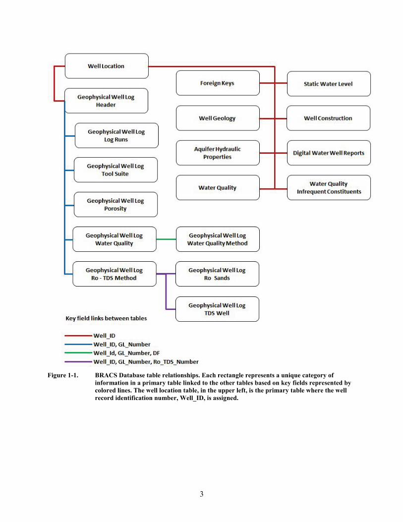
Figure 1-1. BRACS Database table relationships. Each rectangle represents a unique category of
information in a primary table linked to the other tables based on key fields represented by colored lines. The well location table, in the upper left, is the primary table where the well record identification number, Well_ID, is assigned.
4
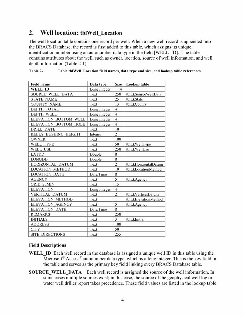
2. Well location: tblWell_Location The well location table contains one record per well. When a new well record is appended into the BRACS Database, the record is first added to this table, which assigns its unique identification number using an autonumber data type in the field [WELL_ID]. The table contains attributes about the well, such as owner, location, source of well information, and well depth information (Table 2-1). Table 2-1. Table tblWell_Location field names, data type and size, and lookup table references.
Field name Data type Size Lookup table WELL_ID Long Integer 4 SOURCE_WELL_DATA Text 250 tblLkSourceWellData STATE_NAME Text 25 tblLkState COUNTY_NAME Text 13 tblLkCounty DEPTH_TOTAL Long Integer 4 DEPTH_WELL Long Integer 4 ELEVATION_BOTTOM_WELL Long Integer 4 ELEVATION_BOTTOM_HOLE Long Integer 4 DRILL_DATE Text 10 KELLY_BUSHING_HEIGHT Integer 2 OWNER Text 100 WELL_TYPE Text 50 tblLkWellType WELL_USE Text 250 tblLkWellUse LATDD Double 8 LONGDD Double 8 HORIZONTAL_DATUM Text 2 tblLkHorizontalDatum LOCATION_METHOD Text 10 tblLkLocationMethod LOCATION_DATE Date/Time 8 AGENCY Text 5 tblLkAgency GRID_25MIN Text 15 ELEVATION Long Integer 4 VERTICAL_DATUM Text 2 tblLkVerticalDatum ELEVATION_METHOD Text 1 tblLkElevationMethod ELEVATION_AGENCY Text 5 tblLkAgency ELEVATION_DATE Date/Time 8 REMARKS Text 250 INITIALS Text 3 tblLkInitial ADDRESS Text 100 CITY Text 50 SITE_DIRECTIONS Text 255
Field Descriptions WELL_ID Each well record in the database is assigned a unique well ID in this table using the
Microsoft® Access® autonumber data type, which is a long integer. This is the key field in the table and serves as the primary key field linking every BRACS Database table.
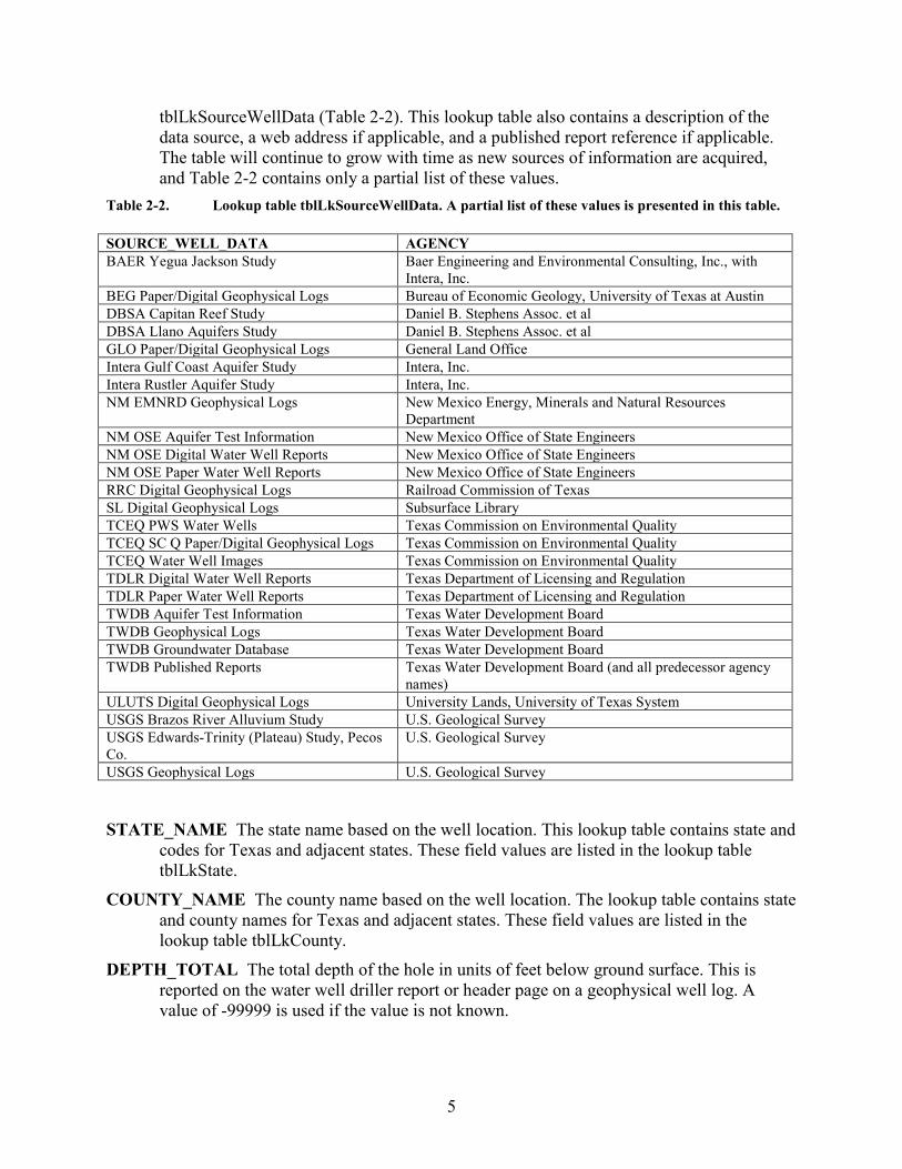
SOURCE_WELL_DATA Each well record is assigned the source of the well information. In some cases multiple sources exist; in this case, the source of the geophysical well log or water well driller report takes precedence. These field values are listed in the lookup table
5
tblLkSourceWellData (Table 2-2). This lookup table also contains a description of the data source, a web address if applicable, and a published report reference if applicable. The table will continue to grow with time as new sources of information are acquired, and Table 2-2 contains only a partial list of these values.
Table 2-2. Lookup table tblLkSourceWellData. A partial list of these values is presented in this table. SOURCE_WELL_DATA AGENCY BAER Yegua Jackson Study Baer Engineering and Environmental Consulting, Inc., with
Intera, Inc. BEG Paper/Digital Geophysical Logs Bureau of Economic Geology, University of Texas at Austin DBSA Capitan Reef Study Daniel B. Stephens Assoc. et al DBSA Llano Aquifers Study Daniel B. Stephens Assoc. et al GLO Paper/Digital Geophysical Logs General Land Office Intera Gulf Coast Aquifer Study Intera, Inc. Intera Rustler Aquifer Study Intera, Inc. NM EMNRD Geophysical Logs New Mexico Energy, Minerals and Natural Resources
Department NM OSE Aquifer Test Information New Mexico Office of State Engineers NM OSE Digital Water Well Reports New Mexico Office of State Engineers NM OSE Paper Water Well Reports New Mexico Office of State Engineers RRC Digital Geophysical Logs Railroad Commission of Texas SL Digital Geophysical Logs Subsurface Library TCEQ PWS Water Wells Texas Commission on Environmental Quality TCEQ SC Q Paper/Digital Geophysical Logs Texas Commission on Environmental Quality TCEQ Water Well Images Texas Commission on Environmental Quality TDLR Digital Water Well Reports Texas Department of Licensing and Regulation TDLR Paper Water Well Reports Texas Department of Licensing and Regulation TWDB Aquifer Test Information Texas Water Development Board TWDB Geophysical Logs Texas Water Development Board TWDB Groundwater Database Texas Water Development Board TWDB Published Reports Texas Water Development Board (and all predecessor agency
names) ULUTS Digital Geophysical Logs University Lands, University of Texas System USGS Brazos River Alluvium Study U.S. Geological Survey USGS Edwards-Trinity (Plateau) Study, Pecos Co.
U.S. Geological Survey
USGS Geophysical Logs U.S. Geological Survey
STATE_NAME The state name based on the well location. This lookup table contains state and
codes for Texas and adjacent states. These field values are listed in the lookup table tblLkState.
COUNTY_NAME The county name based on the well location. The lookup table contains state and county names for Texas and adjacent states. These field values are listed in the lookup table tblLkCounty.
DEPTH_TOTAL The total depth of the hole in units of feet below ground surface. This is reported on the water well driller report or header page on a geophysical well log. A value of -99999 is used if the value is not known.
6
DEPTH_WELL The total depth of the well in units of feet below ground surface. This is reported on the water well driller report. A value of -99999 is used if the value is not known.
ELEVATION_BOTTOM_WELL The elevation of the bottom of the well in units of feet, datum is mean sea level. This is a calculated field, based on the fields: ([elevation] – [depth_well]). A value of -99999 is used if the value is not known.
ELEVATION_BOTTOM_HOLE The elevation of the bottom of the hole in units of feet, datum is mean sea level. This is a calculated field, based on the fields: ([elevation] – [depth_total]). A value of -99999 is used if the value is not known.
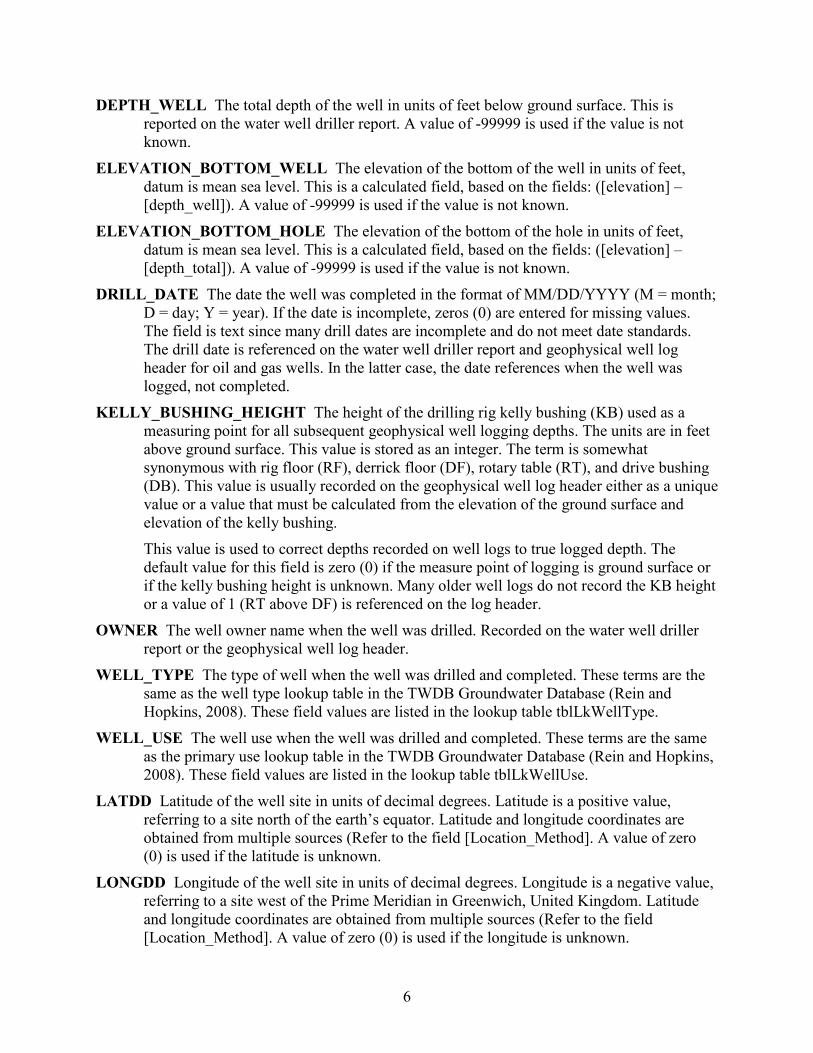
DRILL_DATE The date the well was completed in the format of MM/DD/YYYY (M = month; D = day; Y = year). If the date is incomplete, zeros (0) are entered for missing values. The field is text since many drill dates are incomplete and do not meet date standards. The drill date is referenced on the water well driller report and geophysical well log header for oil and gas wells. In the latter case, the date references when the well was logged, not completed.
KELLY_BUSHING_HEIGHT The height of the drilling rig kelly bushing (KB) used as a measuring point for all subsequent geophysical well logging depths. The units are in feet above ground surface. This value is stored as an integer. The term is somewhat synonymous with rig floor (RF), derrick floor (DF), rotary table (RT), and drive bushing (DB). This value is usually recorded on the geophysical well log header either as a unique value or a value that must be calculated from the elevation of the ground surface and elevation of the kelly bushing. This value is used to correct depths recorded on well logs to true logged depth. The default value for this field is zero (0) if the measure point of logging is ground surface or if the kelly bushing height is unknown. Many older well logs do not record the KB height or a value of 1 (RT above DF) is referenced on the log header.
OWNER The well owner name when the well was drilled. Recorded on the water well driller report or the geophysical well log header.
WELL_TYPE The type of well when the well was drilled and completed. These terms are the same as the well type lookup table in the TWDB Groundwater Database (Rein and Hopkins, 2008). These field values are listed in the lookup table tblLkWellType.
WELL_USE The well use when the well was drilled and completed. These terms are the same as the primary use lookup table in the TWDB Groundwater Database (Rein and Hopkins, 2008). These field values are listed in the lookup table tblLkWellUse.
LATDD Latitude of the well site in units of decimal degrees. Latitude is a positive value, referring to a site north of the earth’s equator. Latitude and longitude coordinates are obtained from multiple sources (Refer to the field [Location_Method]. A value of zero (0) is used if the latitude is unknown.
LONGDD Longitude of the well site in units of decimal degrees. Longitude is a negative value, referring to a site west of the Prime Meridian in Greenwich, United Kingdom. Latitude and longitude coordinates are obtained from multiple sources (Refer to the field [Location_Method]. A value of zero (0) is used if the longitude is unknown.
7
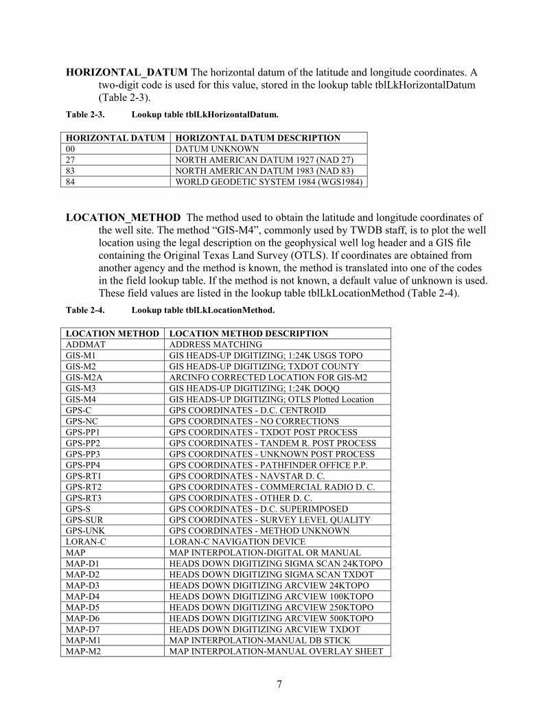
HORIZONTAL_DATUM The horizontal datum of the latitude and longitude coordinates. A two-digit code is used for this value, stored in the lookup table tblLkHorizontalDatum (Table 2-3).
Table 2-3. Lookup table tblLkHorizontalDatum. HORIZONTAL DATUM HORIZONTAL DATUM DESCRIPTION 00 DATUM UNKNOWN 27 NORTH AMERICAN DATUM 1927 (NAD 27) 83 NORTH AMERICAN DATUM 1983 (NAD 83) 84 WORLD GEODETIC SYSTEM 1984 (WGS1984)
LOCATION_METHOD The method used to obtain the latitude and longitude coordinates of
the well site. The method “GIS-M4”, commonly used by TWDB staff, is to plot the well location using the legal description on the geophysical well log header and a GIS file containing the Original Texas Land Survey (OTLS). If coordinates are obtained from another agency and the method is known, the method is translated into one of the codes in the field lookup table. If the method is not known, a default value of unknown is used. These field values are listed in the lookup table tblLkLocationMethod (Table 2-4).
Table 2-4. Lookup table tblLkLocationMethod. LOCATION METHOD LOCATION METHOD DESCRIPTION ADDMAT ADDRESS MATCHING GIS-M1 GIS HEADS-UP DIGITIZING; 1:24K USGS TOPO GIS-M2 GIS HEADS-UP DIGITIZING; TXDOT COUNTY GIS-M2A ARCINFO CORRECTED LOCATION FOR GIS-M2 GIS-M3 GIS HEADS-UP DIGITIZING; 1:24K DOQQ GIS-M4 GIS HEADS-UP DIGITIZING; OTLS Plotted Location GPS-C GPS COORDINATES - D.C. CENTROID GPS-NC GPS COORDINATES - NO CORRECTIONS GPS-PP1 GPS COORDINATES - TXDOT POST PROCESS GPS-PP2 GPS COORDINATES - TANDEM R. POST PROCESS GPS-PP3 GPS COORDINATES - UNKNOWN POST PROCESS GPS-PP4 GPS COORDINATES - PATHFINDER OFFICE P.P. GPS-RT1 GPS COORDINATES - NAVSTAR D. C. GPS-RT2 GPS COORDINATES - COMMERCIAL RADIO D. C. GPS-RT3 GPS COORDINATES - OTHER D. C. GPS-S GPS COORDINATES - D.C. SUPERIMPOSED GPS-SUR GPS COORDINATES - SURVEY LEVEL QUALITY GPS-UNK GPS COORDINATES - METHOD UNKNOWN LORAN-C LORAN-C NAVIGATION DEVICE MAP MAP INTERPOLATION-DIGITAL OR MANUAL MAP-D1 HEADS DOWN DIGITIZING SIGMA SCAN 24KTOPO MAP-D2 HEADS DOWN DIGITIZING SIGMA SCAN TXDOT MAP-D3 HEADS DOWN DIGITIZING ARCVIEW 24KTOPO MAP-D4 HEADS DOWN DIGITIZING ARCVIEW 100KTOPO MAP-D5 HEADS DOWN DIGITIZING ARCVIEW 250KTOPO MAP-D6 HEADS DOWN DIGITIZING ARCVIEW 500KTOPO MAP-D7 HEADS DOWN DIGITIZING ARCVIEW TXDOT MAP-M1 MAP INTERPOLATION-MANUAL DB STICK MAP-M2 MAP INTERPOLATION-MANUAL OVERLAY SHEET
8
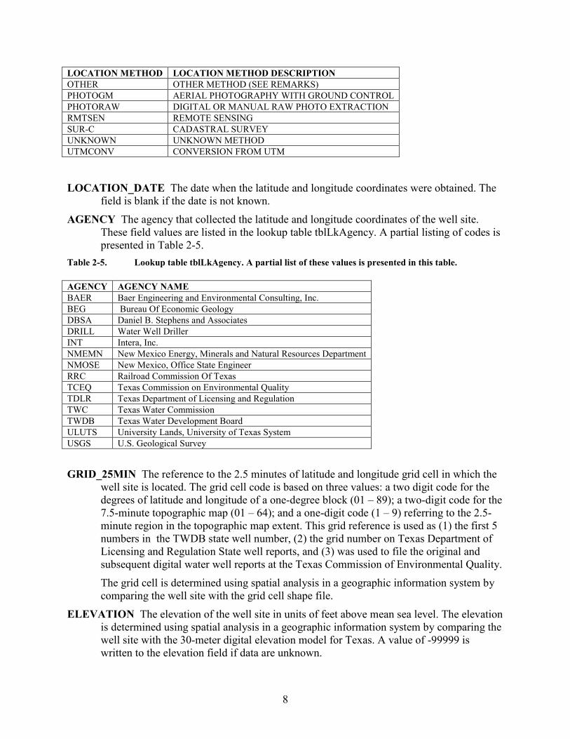
LOCATION METHOD LOCATION METHOD DESCRIPTION OTHER OTHER METHOD (SEE REMARKS) PHOTOGM AERIAL PHOTOGRAPHY WITH GROUND CONTROL PHOTORAW DIGITAL OR MANUAL RAW PHOTO EXTRACTION RMTSEN REMOTE SENSING SUR-C CADASTRAL SURVEY UNKNOWN UNKNOWN METHOD UTMCONV CONVERSION FROM UTM
LOCATION_DATE The date when the latitude and longitude coordinates were obtained. The
field is blank if the date is not known. AGENCY The agency that collected the latitude and longitude coordinates of the well site.
These field values are listed in the lookup table tblLkAgency. A partial listing of codes is presented in Table 2-5.
Table 2-5. Lookup table tblLkAgency. A partial list of these values is presented in this table. AGENCY AGENCY NAME BAER Baer Engineering and Environmental Consulting, Inc. BEG Bureau Of Economic Geology DBSA Daniel B. Stephens and Associates DRILL Water Well Driller INT Intera, Inc. NMEMN New Mexico Energy, Minerals and Natural Resources Department NMOSE New Mexico, Office State Engineer RRC Railroad Commission Of Texas TCEQ Texas Commission on Environmental Quality TDLR Texas Department of Licensing and Regulation TWC Texas Water Commission TWDB Texas Water Development Board ULUTS University Lands, University of Texas System USGS U.S. Geological Survey
GRID_25MIN The reference to the 2.5 minutes of latitude and longitude grid cell in which the
well site is located. The grid cell code is based on three values: a two digit code for the degrees of latitude and longitude of a one-degree block (01 – 89); a two-digit code for the 7.5-minute topographic map (01 – 64); and a one-digit code (1 – 9) referring to the 2.5-minute region in the topographic map extent. This grid reference is used as (1) the first 5 numbers in the TWDB state well number, (2) the grid number on Texas Department of Licensing and Regulation State well reports, and (3) was used to file the original and subsequent digital water well reports at the Texas Commission of Environmental Quality. The grid cell is determined using spatial analysis in a geographic information system by comparing the well site with the grid cell shape file.
ELEVATION The elevation of the well site in units of feet above mean sea level. The elevation is determined using spatial analysis in a geographic information system by comparing the well site with the 30-meter digital elevation model for Texas. A value of -99999 is written to the elevation field if data are unknown.
9
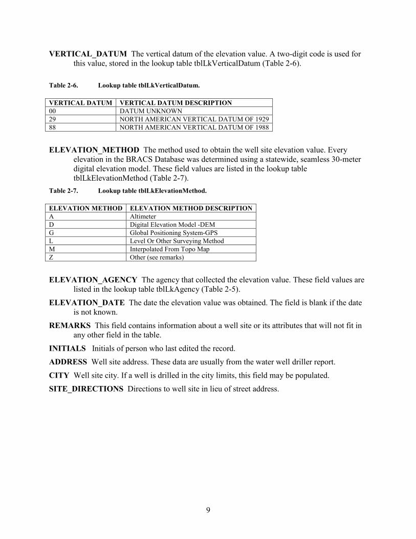
VERTICAL_DATUM The vertical datum of the elevation value. A two-digit code is used for this value, stored in the lookup table tblLkVerticalDatum (Table 2-6).
Table 2-6. Lookup table tblLkVerticalDatum.
ELEVATION_METHOD The method used to obtain the well site elevation value. Every
elevation in the BRACS Database was determined using a statewide, seamless 30-meter digital elevation model. These field values are listed in the lookup table tblLkElevationMethod (Table 2-7).
Table 2-7. Lookup table tblLkElevationMethod. ELEVATION METHOD ELEVATION METHOD DESCRIPTION A Altimeter D Digital Elevation Model -DEM G Global Positioning System-GPS L Level Or Other Surveying Method M Interpolated From Topo Map Z Other (see remarks) ELEVATION_AGENCY The agency that collected the elevation value. These field values are
listed in the lookup table tblLkAgency (Table 2-5). ELEVATION_DATE The date the elevation value was obtained. The field is blank if the date
is not known. REMARKS This field contains information about a well site or its attributes that will not fit in
any other field in the table. INITIALS Initials of person who last edited the record. ADDRESS Well site address. These data are usually from the water well driller report. CITY Well site city. If a well is drilled in the city limits, this field may be populated. SITE_DIRECTIONS Directions to well site in lieu of street address.
VERTICAL DATUM VERTICAL DATUM DESCRIPTION 00 DATUM UNKNOWN 29 NORTH AMERICAN VERTICAL DATUM OF 1929 88 NORTH AMERICAN VERTICAL DATUM OF 1988
10
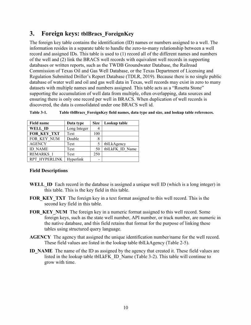
3. Foreign keys: tblBracs_ForeignKey The foreign key table contains the identification (ID) names or numbers assigned to a well. The information resides in a separate table to handle the zero-to-many relationship between a well record and assigned IDs. This table is used to (1) record all of the different names and numbers of the well and (2) link the BRACS well records with equivalent well records in supporting databases or written reports, such as the TWDB Groundwater Database, the Railroad Commission of Texas Oil and Gas Well Database, or the Texas Department of Licensing and Regulation Submitted Driller’s Report Database (TDLR, 2019). Because there is no single public database of water well and oil and gas well data in Texas, well records may exist in zero to many datasets with multiple names and numbers assigned. This table acts as a “Rosetta Stone” supporting the accumulation of well data from multiple, often overlapping, data sources and ensuring there is only one record per well in BRACS. When duplication of well records is discovered, the data is consolidated under one BRACS well id. Table 3-1. Table tblBracs_ForeignKey field names, data type and size, and lookup table references. Field name Data type Size Lookup table WELL_ID Long Integer 4
FOR_KEY_TXT Text 100
FOR_KEY_NUM Double 8
AGENCY Text 5 tblLkAgency ID_NAME Text 50 tblLkFK_ID_Name REMARKS_1 Text 250
RPT_HYPERLINK Hyperlink - Field Descriptions WELL_ID Each record in the database is assigned a unique well ID (which is a long integer) in
this table. This is the key field in this table. FOR_KEY_TXT The foreign key in a text format assigned to this well record. This is the
second key field in this table. FOR_KEY_NUM The foreign key in a numeric format assigned to this well record. Some
foreign keys, such as the state well number, API number, or track number, are numeric in the native database, and this field retains that format for the purpose of linking these tables using structured query language.
AGENCY The agency that assigned the unique identification number/name for the well record. These field values are listed in the lookup table tblLkAgency (Table 2-5).
ID_NAME The name of the ID as assigned by the agency that created it. These field values are listed in the lookup table tblLkFK_ID_Name (Table 3-2). This table will continue to grow with time.
11
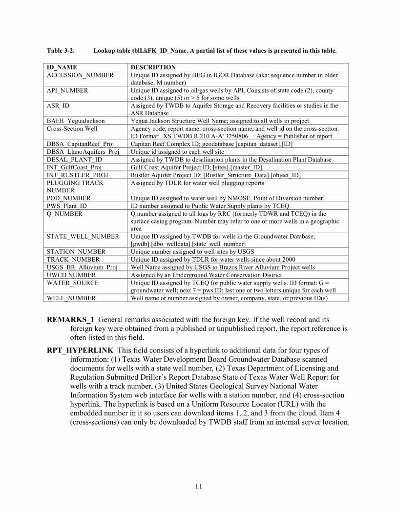
Table 3-2. Lookup table tblLkFK_ID_Name. A partial list of these values is presented in this table. ID_NAME DESCRIPTION ACCESSION_NUMBER Unique ID assigned by BEG in IGOR Database (aka: sequence number in older
database; M number) API_NUMBER Unique ID assigned to oil/gas wells by API. Consists of state code (2), county
code (3), unique (5) or > 5 for some wells ASR_ID Assigned by TWDB to Aquifer Storage and Recovery facilities or studies in the
ASR Database BAER_YeguaJackson Yegua Jackson Structure Well Name; assigned to all wells in project Cross-Section Well Agency code, report name, cross-section name, and well id on the cross-section.
ID Format: XS TWDB R 210 A-A' 3250806 Agency = Publisher of report DBSA_CapitanReef_Proj Capitan Reef Complex ID; geodatabase [capitan_dataset].[ID] DBSA_LlanoAquifers_Proj Unique id assigned to each well site DESAL_PLANT_ID Assigned by TWDB to desalination plants in the Desalination Plant Database INT_GulfCoast_Proj Gulf Coast Aquifer Project ID; [sites].[master_ID] INT_RUSTLER_PROJ Rustler Aquifer Project ID; [Rustler_Structure_Data].[object_ID] PLUGGING TRACK NUMBER
Assigned by TDLR for water well plugging reports
POD_NUMBER Unique ID assigned to water well by NMOSE. Point of Diversion number. PWS_Plant_ID ID number assigned to Public Water Supply plants by TCEQ Q_NUMBER Q number assigned to all logs by RRC (formerly TDWR and TCEQ) in the
surface casing program. Number may refer to one or more wells in a geographic area
STATE_WELL_NUMBER Unique ID assigned by TWDB for wells in the Groundwater Database; [gwdb].[dbo_welldata].[state_well_number]
STATION_NUMBER Unique number assigned to well sites by USGS TRACK_NUMBER Unique ID assigned by TDLR for water wells since about 2000 USGS_BR_Alluvium_Proj Well Name assigned by USGS to Brazos River Alluvium Project wells UWCD NUMBER Assigned by an Underground Water Conservation District WATER_SOURCE Unique ID assigned by TCEQ for public water supply wells. ID format: G =
groundwater well; next 7 = pws ID; last one or two letters unique for each well WELL_NUMBER Well name or number assigned by owner, company, state, or previous ID(s) REMARKS_1 General remarks associated with the foreign key. If the well record and its
foreign key were obtained from a published or unpublished report, the report reference is often listed in this field.
RPT_HYPERLINK This field consists of a hyperlink to additional data for four types of information: (1) Texas Water Development Board Groundwater Database scanned documents for wells with a state well number, (2) Texas Department of Licensing and Regulation Submitted Driller’s Report Database State of Texas Water Well Report for wells with a track number, (3) United States Geological Survey National Water Information System web interface for wells with a station number, and (4) cross-section hyperlink. The hyperlink is based on a Uniform Resource Locator (URL) with the embedded number in it so users can download items 1, 2, and 3 from the cloud. Item 4 (cross-sections) can only be downloaded by TWDB staff from an internal server location.
12
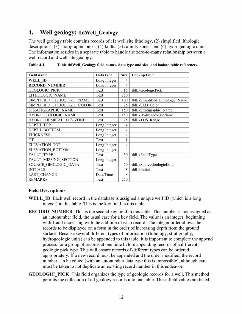
4. Well geology: tblWell_Geology The well geology table contains records of (1) well site lithology, (2) simplified lithologic descriptions, (3) stratigraphic picks, (4) faults, (5) salinity zones, and (6) hydrogeologic units. The information resides in a separate table to handle the zero-to-many relationship between a well record and well site geology. Table 4-1. Table tblWell_Geology field names, data type and size, and lookup table references. Field name Data type Size Lookup table WELL_ID Long Integer 4
RECORD_NUMBER Long Integer 4
GEOLOGIC_PICK Text 15 tblLkGeologicPick LITHOLOGIC_NAME Text 250
SIMPLIFIED_LITHOLOGIC_NAME Text 100 tblLkSimplified_Lithologic_Name SIMPLIFIED_LITHOLOGIC_COLOR Text 25 tblLkSLD_Color STRATIGRAPHIC_NAME Text 150 tblLkStratigraphic_Name HYDROGEOLOGIC_NAME Text 150 tblLkHydrogeologicName HYDROCHEMICAL_TDS_ZONE Text 25 tblLkTDS_Range DEPTH_TOP Long Integer 4
DEPTH_BOTTOM Long Integer 4
THICKNESS Long Integer 4
GT Text 1
ELEVATION_TOP Long Integer 4
ELEVATION_BOTTOM Long Integer 4
FAULT_TYPE Text 50 tblLkFaultType FAULT_MISSING_SECTION Long Integer 4
SOURCE_GEOLOGIC_DATA Text 50 tblLkSourceGeologicData INITIALS Text 3 tblLkInitial LAST_CHANGE Date/Time 8
REMARKS Text 250
Field Descriptions WELL_ID Each well record in the database is assigned a unique well ID (which is a long
integer) in this table. This is the key field in this table. RECORD_NUMBER This is the second key field in this table. This number is not assigned as
an autonumber field, the usual case for a key field. The value is an integer, beginning with 1 and increasing with the addition of each record. The integer order allows the records to be displayed on a form in the order of increasing depth from the ground surface. Because several different types of information (lithology, stratigraphy, hydrogeologic units) can be appended to this table, it is important to complete the append process for a group of records at one time before appending records of a different geologic pick type. This will ensure records of different types can be ordered appropriately. If a new record must be appended and the order modified, the record number can be edited (with an autonumber data type this is impossible), although care must be taken to not duplicate an existing record number in this endeavor.
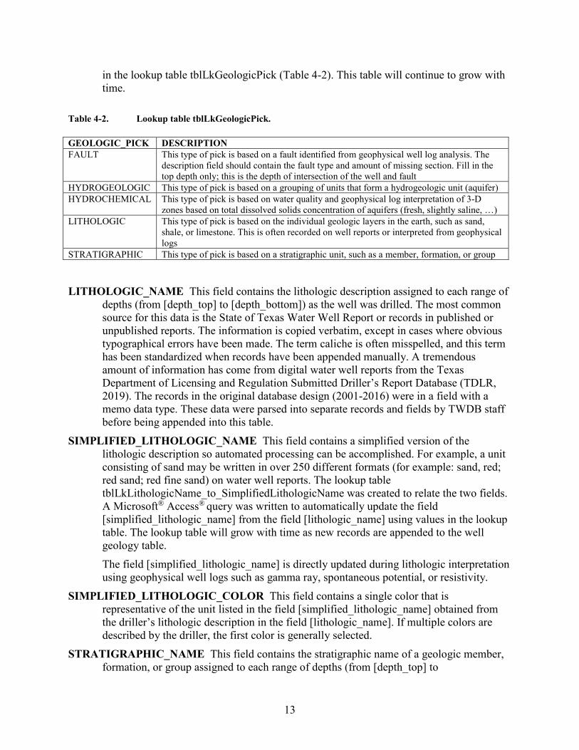
GEOLOGIC_PICK This field organizes the type of geologic records for a well. This method permits the collection of all geology records into one table. These field values are listed
13
in the lookup table tblLkGeologicPick (Table 4-2). This table will continue to grow with time.
Table 4-2. Lookup table tblLkGeologicPick. GEOLOGIC_PICK DESCRIPTION FAULT This type of pick is based on a fault identified from geophysical well log analysis. The
description field should contain the fault type and amount of missing section. Fill in the top depth only; this is the depth of intersection of the well and fault
HYDROGEOLOGIC This type of pick is based on a grouping of units that form a hydrogeologic unit (aquifer) HYDROCHEMICAL This type of pick is based on water quality and geophysical log interpretation of 3-D
zones based on total dissolved solids concentration of aquifers (fresh, slightly saline, …) LITHOLOGIC This type of pick is based on the individual geologic layers in the earth, such as sand,
shale, or limestone. This is often recorded on well reports or interpreted from geophysical logs
STRATIGRAPHIC This type of pick is based on a stratigraphic unit, such as a member, formation, or group
LITHOLOGIC_NAME This field contains the lithologic description assigned to each range of
depths (from [depth_top] to [depth_bottom]) as the well was drilled. The most common source for this data is the State of Texas Water Well Report or records in published or unpublished reports. The information is copied verbatim, except in cases where obvious typographical errors have been made. The term caliche is often misspelled, and this term has been standardized when records have been appended manually. A tremendous amount of information has come from digital water well reports from the Texas Department of Licensing and Regulation Submitted Driller’s Report Database (TDLR, 2019). The records in the original database design (2001-2016) were in a field with a memo data type. These data were parsed into separate records and fields by TWDB staff before being appended into this table.
SIMPLIFIED_LITHOLOGIC_NAME This field contains a simplified version of the lithologic description so automated processing can be accomplished. For example, a unit consisting of sand may be written in over 250 different formats (for example: sand, red; red sand; red fine sand) on water well reports. The lookup table tblLkLithologicName_to_SimplifiedLithologicName was created to relate the two fields. A Microsoft® Access® query was written to automatically update the field [simplified_lithologic_name] from the field [lithologic_name] using values in the lookup table. The lookup table will grow with time as new records are appended to the well geology table. The field [simplified_lithologic_name] is directly updated during lithologic interpretation using geophysical well logs such as gamma ray, spontaneous potential, or resistivity.
SIMPLIFIED_LITHOLOGIC_COLOR This field contains a single color that is representative of the unit listed in the field [simplified_lithologic_name] obtained from the driller’s lithologic description in the field [lithologic_name]. If multiple colors are described by the driller, the first color is generally selected.
STRATIGRAPHIC_NAME This field contains the stratigraphic name of a geologic member, formation, or group assigned to each range of depths (from [depth_top] to
14
[depth_bottom]). In some cases a formation has been subdivided into informal units for hydrogeologic modeling purposes, and this terminology has been used to meet study needs (for example, Jackson Group Upper Unit and Jackson Group Lower Unit). In other cases, a common aquifer name consisting of multiple individual formations has been used in lieu of the actual stratigraphic names (for example, Pecos Valley Alluvium). The lookup table tblLkStratigraphic_Name contains the values for this field and will continue to grow with new studies in the state.
HYDROGEOLOGIC_NAME This field contains the names of hydrogeologic units in Texas and primarily consists of the TWDB designated major and minor aquifers. An aquifer may be subdivided into multiple parts, necessitating the use of the term hydrogeologic name for this field. An aquifer may be composed of part of a geologic formation or several geologic formations.
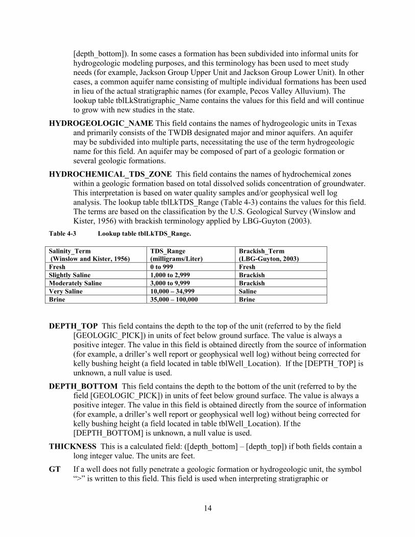
HYDROCHEMICAL_TDS_ZONE This field contains the names of hydrochemical zones within a geologic formation based on total dissolved solids concentration of groundwater. This interpretation is based on water quality samples and/or geophysical well log analysis. The lookup table tblLkTDS_Range (Table 4-3) contains the values for this field. The terms are based on the classification by the U.S. Geological Survey (Winslow and Kister, 1956) with brackish terminology applied by LBG-Guyton (2003).
Table 4-3 Lookup table tblLkTDS_Range. Salinity_Term (Winslow and Kister, 1956)
TDS_Range (milligrams/Liter)
Brackish_Term (LBG-Guyton, 2003)
Fresh 0 to 999 Fresh Slightly Saline 1,000 to 2,999 Brackish Moderately Saline 3,000 to 9,999 Brackish Very Saline 10,000 – 34,999 Saline Brine 35,000 – 100,000 Brine
DEPTH_TOP This field contains the depth to the top of the unit (referred to by the field
[GEOLOGIC_PICK]) in units of feet below ground surface. The value is always a positive integer. The value in this field is obtained directly from the source of information (for example, a driller’s well report or geophysical well log) without being corrected for kelly bushing height (a field located in table tblWell_Location). If the [DEPTH_TOP] is unknown, a null value is used.
DEPTH_BOTTOM This field contains the depth to the bottom of the unit (referred to by the field [GEOLOGIC_PICK]) in units of feet below ground surface. The value is always a positive integer. The value in this field is obtained directly from the source of information (for example, a driller’s well report or geophysical well log) without being corrected for kelly bushing height (a field located in table tblWell_Location). If the [DEPTH_BOTTOM] is unknown, a null value is used.
THICKNESS This is a calculated field: ([depth_bottom] – [depth_top]) if both fields contain a long integer value. The units are feet.
GT If a well does not fully penetrate a geologic formation or hydrogeologic unit, the symbol “>” is written to this field. This field is used when interpreting stratigraphic or
15
hydrogeologic picks. The field [DEPTH_BOTTOM] must remain null because the well is not deep enough to determine the value.
This field will also contain the symbol “>” if there is a fault within the stratigraphic unit that has reduced the total thickness of the formation. This is used as a flag when preparing GIS raster maps by TWDB staff so these wells are not considered for automated raster surface and point files. The field [DEPTH_BOTTOM] may contain a value.
ELEVATION_TOP This field contains the elevation to the top of the unit (referred to by the field [GEOLOGIC_PICK]) in units of feet, datum is mean sea level. This field is corrected for kelly bushing height. This is a calculated field: ([elevation] – ([depth_top] – [kelly_bushing_height])). A value of -99999 is written to the field if no data are present for this record. The value may be positive or negative based on its relation to mean sea level.
ELEVATION_BOTTOM This field contains the elevation to the bottom of the unit (referred to by the field [GEOLOGIC_PICK]) in units of feet, datum is mean sea level. This field is corrected for kelly bushing height. This is a calculated field: ([elevation] – ([depth_bottom] – [kelly_bushing_height])). A value of -99999 is written to the field if no data are present for this record. The value may be positive or negative based on its relation to mean sea level.
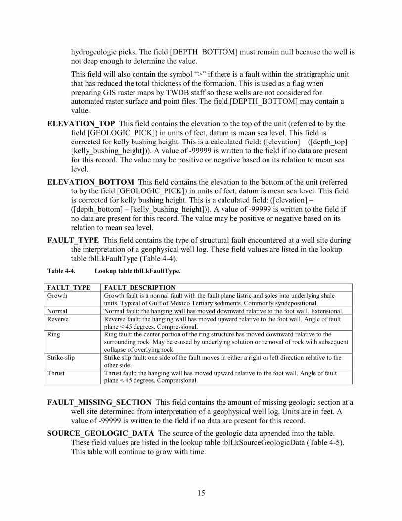
FAULT_TYPE This field contains the type of structural fault encountered at a well site during the interpretation of a geophysical well log. These field values are listed in the lookup table tblLkFaultType (Table 4-4).
Table 4-4. Lookup table tblLkFaultType. FAULT_TYPE FAULT_DESCRIPTION Growth Growth fault is a normal fault with the fault plane listric and soles into underlying shale
units. Typical of Gulf of Mexico Tertiary sediments. Commonly syndepositional. Normal Normal fault: the hanging wall has moved downward relative to the foot wall. Extensional. Reverse Reverse fault: the hanging wall has moved upward relative to the foot wall. Angle of fault
plane < 45 degrees. Compressional. Ring Ring fault: the center portion of the ring structure has moved downward relative to the
surrounding rock. May be caused by underlying solution or removal of rock with subsequent collapse of overlying rock.
Strike-slip Strike slip fault: one side of the fault moves in either a right or left direction relative to the other side.
Thrust Thrust fault: the hanging wall has moved upward relative to the foot wall. Angle of fault plane < 45 degrees. Compressional.
FAULT_MISSING_SECTION This field contains the amount of missing geologic section at a
well site determined from interpretation of a geophysical well log. Units are in feet. A value of -99999 is written to the field if no data are present for this record.
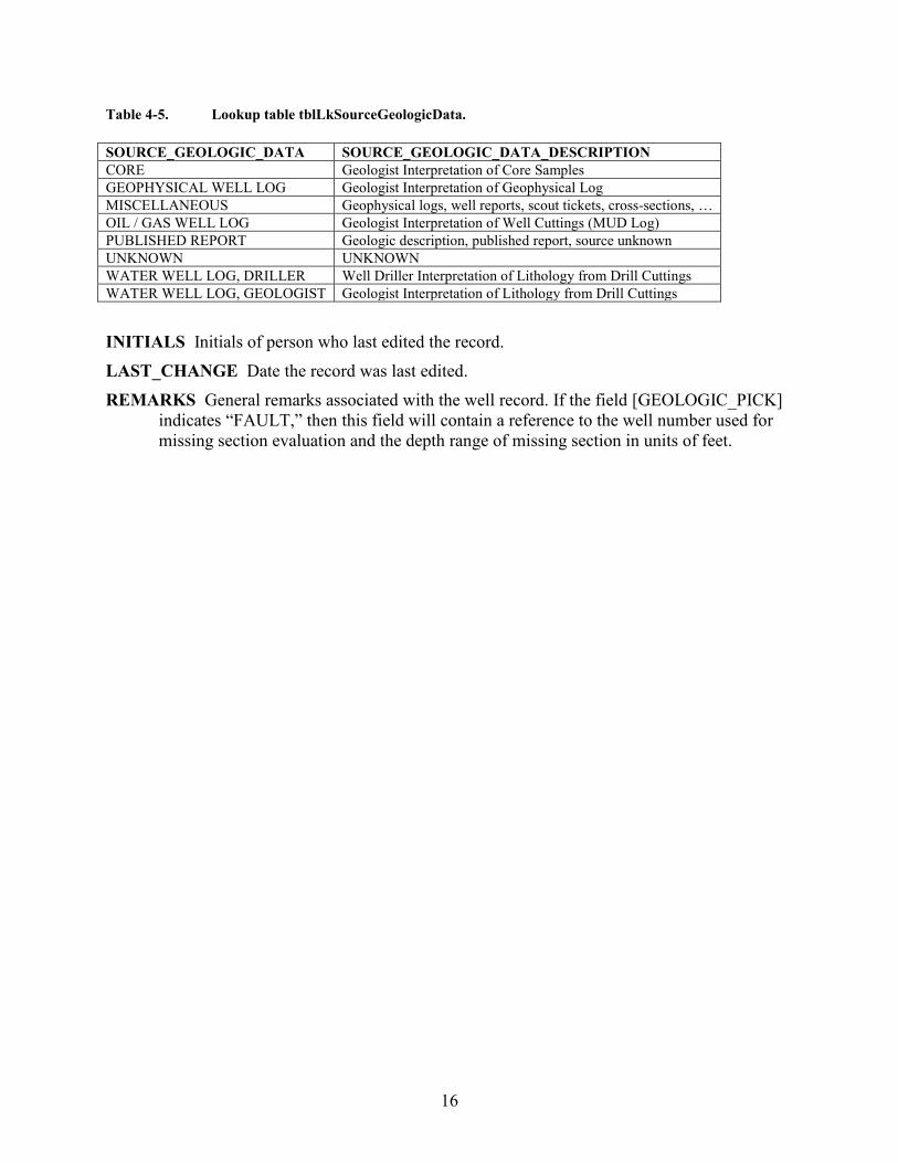
SOURCE_GEOLOGIC_DATA The source of the geologic data appended into the table. These field values are listed in the lookup table tblLkSourceGeologicData (Table 4-5). This table will continue to grow with time.
16
Table 4-5. Lookup table tblLkSourceGeologicData. SOURCE_GEOLOGIC_DATA SOURCE_GEOLOGIC_DATA_DESCRIPTION CORE Geologist Interpretation of Core Samples GEOPHYSICAL WELL LOG Geologist Interpretation of Geophysical Log MISCELLANEOUS Geophysical logs, well reports, scout tickets, cross-sections, … OIL / GAS WELL LOG Geologist Interpretation of Well Cuttings (MUD Log) PUBLISHED REPORT Geologic description, published report, source unknown UNKNOWN UNKNOWN WATER WELL LOG, DRILLER Well Driller Interpretation of Lithology from Drill Cuttings WATER WELL LOG, GEOLOGIST Geologist Interpretation of Lithology from Drill Cuttings INITIALS Initials of person who last edited the record. LAST_CHANGE Date the record was last edited. REMARKS General remarks associated with the well record. If the field [GEOLOGIC_PICK]
indicates “FAULT,” then this field will contain a reference to the well number used for missing section evaluation and the depth range of missing section in units of feet.
17
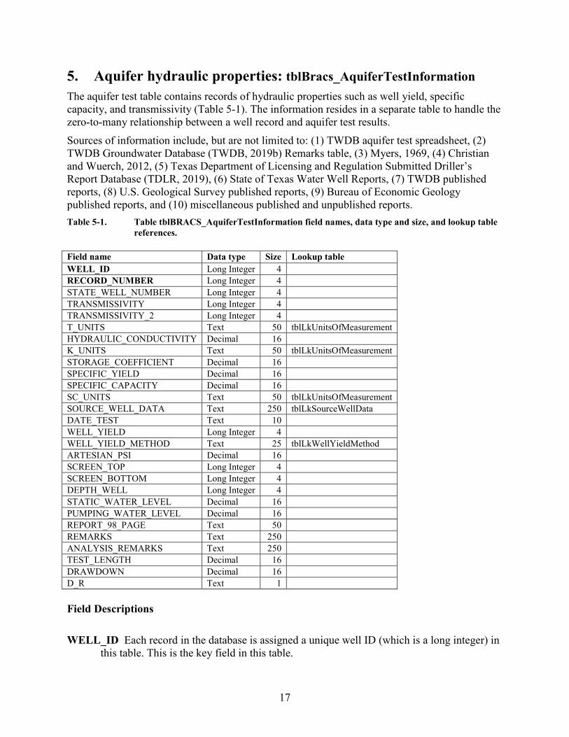
5. Aquifer hydraulic properties: tblBracs_AquiferTestInformation The aquifer test table contains records of hydraulic properties such as well yield, specific capacity, and transmissivity (Table 5-1). The information resides in a separate table to handle the zero-to-many relationship between a well record and aquifer test results. Sources of information include, but are not limited to: (1) TWDB aquifer test spreadsheet, (2) TWDB Groundwater Database (TWDB, 2019b) Remarks table, (3) Myers, 1969, (4) Christian and Wuerch, 2012, (5) Texas Department of Licensing and Regulation Submitted Driller’s Report Database (TDLR, 2019), (6) State of Texas Water Well Reports, (7) TWDB published reports, (8) U.S. Geological Survey published reports, (9) Bureau of Economic Geology published reports, and (10) miscellaneous published and unpublished reports. Table 5-1. Table tblBRACS_AquiferTestInformation field names, data type and size, and lookup table
references. Field name Data type Size Lookup table WELL_ID Long Integer 4
RECORD_NUMBER Long Integer 4
STATE_WELL_NUMBER Long Integer 4
TRANSMISSIVITY Long Integer 4
TRANSMISSIVITY_2 Long Integer 4
T_UNITS Text 50 tblLkUnitsOfMeasurement HYDRAULIC_CONDUCTIVITY Decimal 16
K_UNITS Text 50 tblLkUnitsOfMeasurement STORAGE_COEFFICIENT Decimal 16
SPECIFIC_YIELD Decimal 16
SPECIFIC_CAPACITY Decimal 16
SC_UNITS Text 50 tblLkUnitsOfMeasurement SOURCE_WELL_DATA Text 250 tblLkSourceWellData DATE_TEST Text 10
WELL_YIELD Long Integer 4
WELL_YIELD_METHOD Text 25 tblLkWellYieldMethod ARTESIAN_PSI Decimal 16
SCREEN_TOP Long Integer 4
SCREEN_BOTTOM Long Integer 4
DEPTH_WELL Long Integer 4
STATIC_WATER_LEVEL Decimal 16
PUMPING_WATER_LEVEL Decimal 16
REPORT_98_PAGE Text 50
REMARKS Text 250
ANALYSIS_REMARKS Text 250
TEST_LENGTH Decimal 16
DRAWDOWN Decimal 16
D_R Text 1
Field Descriptions WELL_ID Each record in the database is assigned a unique well ID (which is a long integer) in
this table. This is the key field in this table.
18
RECORD_NUMBER This is the second key field in this table. This number is not assigned as an autonumber field, as in the usual case for a key field. The value is an integer, beginning with 1 and increasing with the addition of each record for a specific well.
STATE_WELL_NUMBER This field contains the TWDB assigned state well number. Each well in the TWDB Groundwater Database has a state well number. Some, but not all, wells in this table have been assigned a state well number; for those without, this field contains a value of zero (0).
TRANSMISSIVITY This field contains a transmissivity value measured for the aquifer(s) at the well site. Transmissivity units are specified in the field [t_units]. The source of the information is specified in the field [source_well_data]. If two transmissivity values are provided for a test, the larger value is written to this field and the smaller of the two values is written to the field [transmissivity_2]. A value of -99999 is written to the field if no data are present for this record.
TRANSMISSIVITY_2 This field contains a transmissivity value measured for the aquifer(s) at the well site. Transmissivity units are specified in the field [t_units]. The source of the information is specified in the field [source_well_data]. If two transmissivity values are provided for a test, the smaller value is written to this field and the larger of the two values is written to the field [transmissivity]. A value of -99999 is written to the field if no data are present for this record.
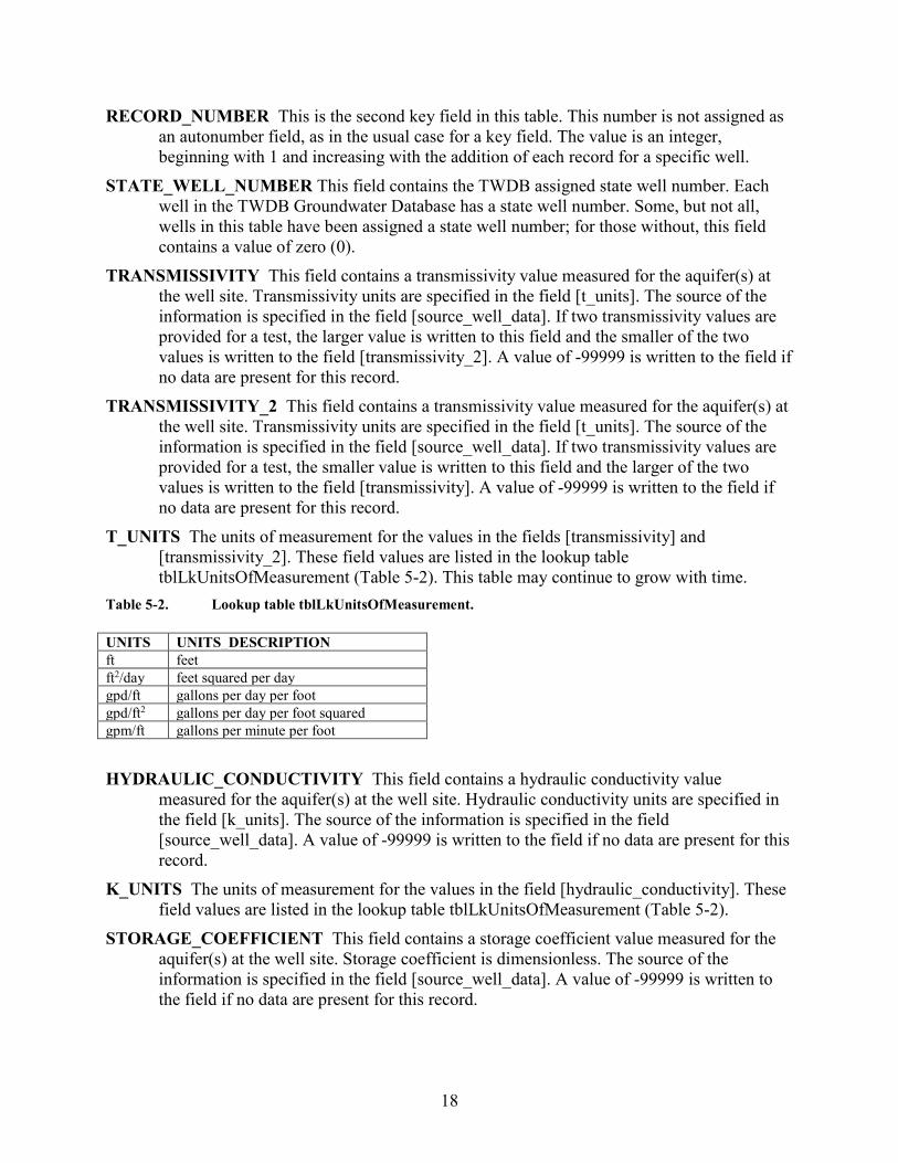
T_UNITS The units of measurement for the values in the fields [transmissivity] and [transmissivity_2]. These field values are listed in the lookup table tblLkUnitsOfMeasurement (Table 5-2). This table may continue to grow with time.
Table 5-2. Lookup table tblLkUnitsOfMeasurement. UNITS UNITS_DESCRIPTION ft feet ft2/day feet squared per day gpd/ft gallons per day per foot gpd/ft2 gallons per day per foot squared gpm/ft gallons per minute per foot HYDRAULIC_CONDUCTIVITY This field contains a hydraulic conductivity value
measured for the aquifer(s) at the well site. Hydraulic conductivity units are specified in the field [k_units]. The source of the information is specified in the field [source_well_data]. A value of -99999 is written to the field if no data are present for this record.
K_UNITS The units of measurement for the values in the field [hydraulic_conductivity]. These field values are listed in the lookup table tblLkUnitsOfMeasurement (Table 5-2).
STORAGE_COEFFICIENT This field contains a storage coefficient value measured for the aquifer(s) at the well site. Storage coefficient is dimensionless. The source of the information is specified in the field [source_well_data]. A value of -99999 is written to the field if no data are present for this record.
19
SPECIFIC_YIELD This field contains a specific yield value measured for the aquifer(s) at the well site. Specific yield is dimensionless. The source of the information is specified in the field [source_well_data]. A value of -99999 is written to the field if no data are present for this record.
SPECIFIC_CAPACITY This field contains a specific capacity value measured for the aquifer(s) at the well site. Specific capacity units are specified in the field [sc_units]. Specific capacity is calculated from: ([well_yield] / [drawdown]). A value of -99999 is written to the field if no data are present for this record.
SC_UNITS The units of measurement for the values in the field [specific_capacity]. These field values are listed in the lookup table tblLkUnitsOfMeasurement (Table 5-2).
SOURCE_WELL_DATA Each aquifer test record contains a source of the well information. In some cases multiple sources exist; see the fields [report_98_page], [remarks], or [analysis_remarks] for additional information.
DATE_TEST The date the well was tested in the format of MM/DD/YYYY (M = month; D = day; Y = year). If the date is incomplete, zeros (0) are entered for missing values. The field data type is text since many test dates are incomplete and do not meet date standards.
WELL_YIELD The pumping rate of the well in units of gallons per minute (gpm). In cases of variable rate pumping tests, the original data will need to be reviewed. A value of -99999 is written to the field if no data are present for this record.
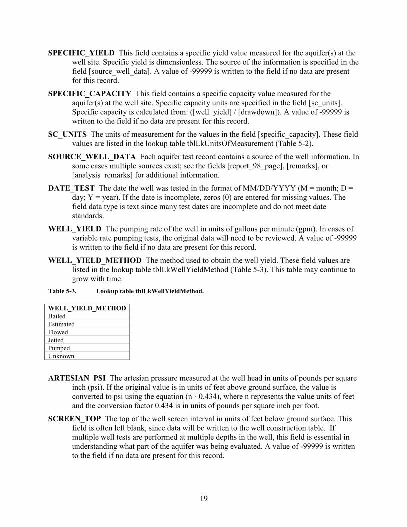
WELL_YIELD_METHOD The method used to obtain the well yield. These field values are listed in the lookup table tblLkWellYieldMethod (Table 5-3). This table may continue to grow with time.
Table 5-3. Lookup table tblLkWellYieldMethod. WELL_YIELD_METHOD Bailed Estimated Flowed Jetted Pumped Unknown ARTESIAN_PSI The artesian pressure measured at the well head in units of pounds per square
inch (psi). If the original value is in units of feet above ground surface, the value is converted to psi using the equation (n · 0.434), where n represents the value units of feet and the conversion factor 0.434 is in units of pounds per square inch per foot.
SCREEN_TOP The top of the well screen interval in units of feet below ground surface. This field is often left blank, since data will be written to the well construction table. If multiple well tests are performed at multiple depths in the well, this field is essential in understanding what part of the aquifer was being evaluated. A value of -99999 is written to the field if no data are present for this record.
20
SCREEN_BOTTOM The bottom of the well screen interval in units of feet below ground surface. This field is often left blank, since data will be written to the well construction table. If multiple well tests are performed at multiple depths in the well, this field is essential in understanding what part of the aquifer was being evaluated. A value of -99999 is written to the field if no data are present for this record.
DEPTH_WELL The total depth of the well in units of feet below ground surface. This is reported on the water well driller report. A value of -99999 is written to the field if no data are present for this record.
STATIC_WATER_LEVEL The static water level measured at the time of the aquifer test in units of feet below ground surface. This value is negative if the static water level is below the ground surface and positive if above the ground surface (artesian well). A value of -99999 is written to the field if no data are present for this record.
PUMPING_WATER_LEVEL The pumping water level measured at the time of the aquifer test in units of feet below ground surface. This value is negative. A value of -99999 is written to the field if no data are present for this record.
REPORT_98_PAGE This field contains the page number cross-reference to additional data in TWDB Report 98 (Myers, 1969).
REMARKS General remarks pertaining to the aquifer test information. ANALYSIS_REMARKS This field contains remarks about the aquifer test information. Many
references to the original report may be written to this field. The value of R-98 refers to the Myers (1969) report. Additional references provide the TWDB report number and table number. Additional information may be present in the TWDB Groundwater Database digital well reports.
TEST_LENGTH The length of the pumping test in units of hours. A value of -99999 is written to the field if no data are present for this record.
DRAWDOWN The drawdown in water level at the end of the aquifer test in units of feet below ground surface. This value is a positive integer. A value of -99999 is written to the field if no data are present for this record.
D_R This field contains a one-letter code specifying the type of aquifer test performed: D = drawdown test; R = recovery test.
21
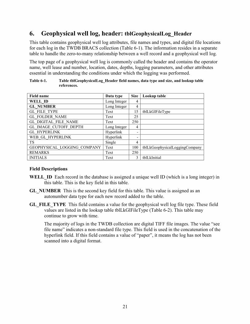
6. Geophysical well log, header: tblGeophysicalLog_Header This table contains geophysical well log attributes, file names and types, and digital file locations for each log in the TWDB BRACS collection (Table 6-1). The information resides in a separate table to handle the zero-to-many relationship between a well record and a geophysical well log. The top page of a geophysical well log is commonly called the header and contains the operator name, well lease and number, location, dates, depths, logging parameters, and other attributes essential in understanding the conditions under which the logging was performed. Table 6-1. Table tblGeophysicalLog_Header field names, data type and size, and lookup table
references. Field name Data type Size Lookup table WELL_ID Long Integer 4
GL_NUMBER Long Integer 4
GL_FILE_TYPE Text 15 tblLkGlFileType GL_FOLDER_NAME Text 25
GL_DIGITAL_FILE_NAME Text 250
GL_IMAGE_CUTOFF_DEPTH Long Integer 4
GL_HYPERLINK Hyperlink -
WEB_GL_HYPERLINK Hyperlink - TS Single 4
GEOPHYSICAL_LOGGING_COMPANY Text 100 tblLkGeophysicalLoggingCompany REMARKS Text 250
INITIALS Text 3 tblLkInitial Field Descriptions WELL_ID Each record in the database is assigned a unique well ID (which is a long integer) in
this table. This is the key field in this table. GL_NUMBER This is the second key field for this table. This value is assigned as an
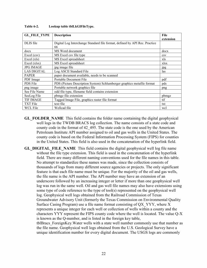
autonumber data type for each new record added to the table. GL_FILE_TYPE This field contains a value for the geophysical well log file type. These field
values are listed in the lookup table tblLkGlFileType (Table 6-2). This table may continue to grow with time. The majority of logs in the TWDB collection are digital TIFF file images. The value “see file name” indicates a non-standard file type. This field is used in the concatenation of the hyperlink field. If this field contains a value of “paper”, it means the log has not been scanned into a digital format.
22
Table 6-2. Lookup table tblLkGlFileType. GL_FILE_TYPE Description File
extension DLIS file Digital Log Interchange Standard file format, defined by API Rec. Practice
66
docx MS Word document docx Excel (csv) MS Excel csv file type csv Excel (xls) MS Excel spreadsheet xls Excel (xlsx) MS Excel spreadsheet xlsx JPG IMAGE jpg image file jpg LAS DIGITAL Log ASCII Standard File las PAPER paper document available, needs to be scanned PDF Image Portable Document File pdf PDS File PDS (Picture Description System) Schlumberger graphics metafile format pds png image Portable network graphics file png See File Name odd file type, filename field contains extension SeeLog File pbmgz file extension pbmgz TIF IMAGE Tagged Image File, graphics raster file format tif TXT File text file txt WCL File Wellcad file wcl
GL_FOLDER_NAME This field contains the folder name containing the digital geophysical well logs in the TWDB BRACS log collection. The name consists of a state code and county code in the format of 42_495. The state code is the one used by the American Petroleum Institute API number assigned to oil and gas wells in the United States. The county code is based on the Federal Information Processing System (FIPS) for counties in the United States. This field is also used in the concatenation of the hyperlink field.
GL_DIGITAL_FILE_NAME This field contains the digital geophysical well log file name without the file type extension. This field is used in the concatenation of the hyperlink field. There are many different naming conventions used for the file names in this table. No attempt to standardize these names was made, since the collection consists of thousands of logs from many different source agencies or projects. The only significant feature is that each file name must be unique. For the majority of the oil and gas wells, the file name is the API number. The API number may have an extension of an underscore followed by an increasing integer or letter if more than one geophysical well log was run in the same well. Oil and gas well file names may also have extensions using some type of code reference to the type of tool(s) represented on the geophysical well log. Geophysical well logs obtained from the Railroad Commission of Texas Groundwater Advisory Unit (formerly the Texas Commission on Environmental Quality Surface Casing Program) use a file name format consisting of QX_YYY, where X represents a unique integer for each well or collection of wells within a county and the characters YYY represent the FIPS county code where the well is located. The value Q-X is known as the Q-number, and is listed in the foreign key table, tblBracs_ForeignKey.Water wells with a state well number commonly use that number as the file name. Geophysical well logs obtained from the U.S. Geological Survey have a unique identification number for every digital document. The USGS logs are commonly
23
run in LAS and PDF format with supporting documents (including field sheets) in various file formats.
GL_IMAGE_CUTOFF_DEPTH The total depth represented on the digital log image (when image does not go to total depth of the well). The units are feet below ground surface. Value of -99999 indicates image does go to total depth. This situation arises when partial logs are imaged; in some cases, the deeper parts of the log are not available because of confidentiality. This field can be used to adjust the net sand and sand percent calculations, since it is not possible to fully evaluate a formation to total depth if part of the geophysical well log is not available for interpretation.
GL_HYPERLINK This field permits the digital geophysical well logs to be opened from a Microsoft® Access® form. The data type for this field is hyperlink, and the data format is based on the navigation path within a computer’s file system, called the universal naming convention (UNC). The ability to access these digital files using this technique has saved tremendous amounts of time and ensures that the correct document is opened. This field is created with a query that concatenates several other fields. The syntax of the Microsoft® Access® Update query is presented here so users of the database and digital geophysical well logs can modify their version of the BRACS Database and file structure to meet their needs:
UPDATE tblGeophysicalLog_Header SET tblGeophysicalLog_Header.GL_HYPERLINK = "#B:\GeophysicalWellLogs\" & [GL_FOLDER_NAME] & "\" & [GL_DIGITAL_FILE_NAME] & ".tif#" WHERE (((tblGeophysicalLog_Header.GL_FILE_TYPE) = "tif image"));
One can substitute the pathname B:\GeophysicalWellLogs\ for any other pathname on a local computer or network drive. If the folder structure holding the digital documents is different, the query can be modified to accept this. One will need to perform several queries to account for the concatenation of different file type extensions. The query will need to be modified in the where clause (gl_file_type) and the suffix in the hyperlink.
WEB_GL_HYPERLINK This field permits the digital geophysical well logs to be opened from a Microsoft® Access® form. The data type for this field is hyperlink, and the data format is based on the uniform resource locator (URL). This field is created with a query that concatenates several other fields. The geophysical well log collection at the TWDB is synchronized with the collection on the cloud (accessed with TWDB Water Data Interactive, or WDI). It takes one week (20 percent of the collection each night) to fully update the cloud collection. By adding this URL hyperlink to the public version of the BRACS Database, stakeholders can access the logs directly from the public version of the BRACS Database.
TS This field contains the near-surface temperature at the well site is commonly acquired from multidecadal mean annual surface temperature records near the well location (for example, Larkin and Bomar, 1983). Temperature is in units of degrees Fahrenheit. A low temperature value associated with mud or mud filtrate is located on the geophysical well log header and is often assumed to represent the surface temperature, however this should not be used for log analysis. This field is completed only for geophysical well logs used for interpretation of total dissolved solids. The purpose of the field is to determine, with
24
the temperature bottom hole, the downhole temperature of the formation of interest in order to correct the resistivity values at this depth.
GEOPHYSICAL_LOGGING_COMPANY This field contains the name of the company that created the geophysical well log. This field is completed only for geophysical well logs used for interpretation of total dissolved solids. These field values are listed in the lookup table tblLkGeophysicalLoggingCompany.
REMARKS This field may include observations on tool scale changes, problems encountered during logging as noted on the log header, source of this specific digital log image, source of the extrapolated temperature bottom hole, and quality of digital log image.
INITIALS Initials of person who last edited the record.
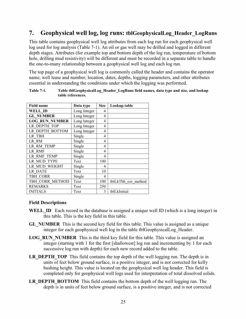
25
7. Geophysical well log, log runs: tblGeophysicalLog_Header_LogRuns This table contains geophysical well log attributes from each log run for each geophysical well log used for log analysis (Table 7-1). An oil or gas well may be drilled and logged in different depth stages. Attributes (for example top and bottom depth of the log run, temperature of bottom hole, drilling mud resistivity) will be different and must be recorded in a separate table to handle the one-to-many relationship between a geophysical well log and each log run. The top page of a geophysical well log is commonly called the header and contains the operator name, well lease and number, location, dates, depths, logging parameters, and other attributes essential in understanding the conditions under which the logging was performed. Table 7-1. Table tblGeophysicalLog_Header_LogRuns field names, data type and size, and lookup
table references. Field name Data type Size Lookup table WELL_ID Long Integer 4
GL_NUMBER Long Integer 4
LOG_RUN_NUMBER Long Integer 4
LR_DEPTH_TOP Long Integer 4
LR_DEPTH_BOTTOM Long Integer 4 LR_TBH Single 4
LR_RM Single 4
LR_RM_TEMP Single 4
LR_RMF Single 4
LR_RMF_TEMP Single 4
LR_MUD_TYPE Text 100
LR_MUD_WEIGHT Single 4 LR_DATE Text 10 TBH_CORR Single 4 TBH_CORR_METHOD Text 100 tblLkTbh_cor_method REMARKS Text 250
INITIALS Text 3 tblLkInitial Field Descriptions WELL_ID Each record in the database is assigned a unique well ID (which is a long integer) in
this table. This is the key field in this table. GL_NUMBER This is the second key field for this table. This value is assigned as a unique
integer for each geophysical well log in the table tblGeophysicalLog_Header. LOG_RUN_NUMBER This is the third key field for this table. This value is assigned an
integer (starting with 1 for the first [shallowest] log run and incrementing by 1 for each successive log run with depth) for each new record added to the table.
LR_DEPTH_TOP This field contains the top depth of the well logging run. The depth is in units of feet below ground surface, is a positive integer, and is not corrected for kelly bushing height. This value is located on the geophysical well log header. This field is completed only for geophysical well logs used for interpretation of total dissolved solids.
LR_DEPTH_BOTTOM This field contains the bottom depth of the well logging run. The depth is in units of feet below ground surface, is a positive integer, and is not corrected
26
for kelly bushing height. This value is located on the geophysical well log header. This field is completed only for geophysical well logs used for interpretation of total dissolved solids.
LR_TBH This field contains the temperature at the bottom of the hole for this specific logging run. Temperature is in units of degrees Fahrenheit. This value is usually located on the geophysical well log header. In some cases the TBH value is not listed on the geophysical well log and a value is determined using the total depth of the well and the geothermal gradient from a deeper logging run of this wells or a nearby well of similar depth; this is usually noted in the field [Remarks]. This field is completed only for geophysical well logs used for interpretation of total dissolved solids. TBH values of 100 are almost universally incorrect, a default value written on the log by the logging crew. These values, when discovered, need to be calculated with a nearby log and the geothermal gradient.
LR_RM This field contains the resistivity of the drilling mud for this specific logging run. Resistivity is in units of ohm-meter. This value is located on the geophysical well log header. This field is completed only for geophysical well logs used for interpretation of total dissolved solids.
LR_RM_TEMP This field contains the temperature of the drilling mud for this specific logging run. Temperature is in units of degrees Fahrenheit. This value is located on the geophysical well log header. This field is completed only for geophysical well logs used for interpretation of total dissolved solids.
LR_RMF This field contains the resistivity of the drilling mud filtrate for this specific logging run. Resistivity is in units of ohm-meter. This value is located on the geophysical well log header. If the [LR_RMF] value was calculated from the [RM] value, the method is recorded in the field [REMARKS] and a full description of the technique is found in Estepp (1998). This field is completed only for geophysical well logs used for interpretation of total dissolved solids.
LR_RMF_TEMP This field contains the temperature of the drilling mud filtrate for this specific logging run. Temperature is in units of degrees Fahrenheit. This value is located on the geophysical well log header. This field is completed only for geophysical well logs used for interpretation of total dissolved solids.
LR_MUD_TYPE This field contains the type of drilling mud used for this specific logging run and is entered from data presented on the geophysical well log. Drilling mud programs may change during different stages (runs) of well development. This field is completed only for geophysical well logs used for interpretation of total dissolved solids. The mud type name/description is transcribed verbatim from the log and often contains logging industry product names/acronyms.
LR_MUD_WEIGHT This field contains the mud weight used for this specific logging run. The units are in pounds per gallon. This field is used for calculation of Rmf from a Rm value. Aliases used on the log can include: fluid densisty.
LR_DATE This is the date for this specific logging run. The format is MM/DD/YYYY in text format. Zeros are substituted for missing values.

27
TBH_CORR This field contains a corrected temperature at the bottom of the hole for this specific logging run. Temperature is in units of degrees Fahrenheit. The correction is based on a method listed in the field [TBH_CORR_METHOD]. This field is completed only for geophysical well logs used for interpretation of total dissolved solids.
TBH_CORR_METHOD The method used to obtain the method to correct the temperature bottom hole. These field values are listed in the lookup table tblLkTBH_CORR_METHOD (Table 7-2). The field [DESCRIPTION] contains the report reference. This table may continue to grow with time.
Table 7-2. Lookup table tblLkTbh_Corr_Method. TBH_CORR_METHOD DESCRIPTION SMU_Harrison Southern Methodist University modification of Harrison Method. Refer to:
Blackwell, D, Richards, M., and Stepp, P., 2010, Texas geothermal assessment for the I 35 corridor east Southern Methodist University, contract report to the Texas State Energy Cons
Kehle Kehle Method. Refer to: Blackwell, D, Richards, M., and Stepp, P., 2010, Texas geothermal assessment for the I 35 corridor east Southern Methodist University, contract report to the Texas State Energy Cons
n/a Not applicable REMARKS This field may include observations on problems encountered during logging as
noted on the log header, calculation of fields such as [LR_TBH] or methods of calculation used to determine [Rmf] from [Rm], and associated parameters.
INITIALS Initials of person who last edited the record.

28
8. Geophysical well log, tool suite: tblGeophysicalLog_Suite This table contains the list of geophysical logging tools represented on a geophysical well log (Table 8-1). The information resides in a separate table to handle the one-to-many relationship between a geophysical well log and the individual tools. Each tool has a start and end depth in units of feet below ground surface. Table 8-1. Table tblGeophysicalLog_Suite field names, data type and size, and lookup table references. Field name Data type Size Lookup table WELL_ID Long Integer 4
GL_NUMBER Long Integer 4
GEOPHYSICAL_LOG Text 50 tblLkGeophysicalLogs GL_CODE Text 25 tblLkGeophysicalLogs DEPTH_TOP Long Integer 4
DEPTH_BOTTOM Long Integer 4
REMARKS Text 250
Field Descriptions WELL_ID Each record in the database is assigned a unique well ID (which is a long integer) in
this table. This is the key field in this table. GL_NUMBER This is the second key field for this table. This value is assigned as a unique
integer for each geophysical well log. This value is assigned as a unique integer for each geophysical well log in the table tblGeophysicalLog_Header.
GEOPHYSICAL_LOG This is the third key field for this table. Each geophysical well log tool represents a unique record. This field is tied to the lookup table tblLkGeophysicalLogs. There are a number of general and company-specific naming conventions for these tools.
GL_CODE The sole purpose of this field is to facilitate data entry by typing a simple code to load the geophysical log name. This is achieved using a data entry form. The code resides in the lookup table tblLkGeophysicalLogs and can be modified to meet the user’s needs.
DEPTH_TOP The depth to the top of the interval logged by the geophysical tool (start depth) in units of feet below ground surface. This depth is not corrected for kelly bushing height. The user should attempt to determine this value to the nearest 10 feet. Logging tools start and end recording at different depths due to placement on the logging tool string.
DEPTH_BOTTOM The depth to the bottom of the interval logged by the geophysical tool (end depth) in units of feet below ground surface. This depth is not corrected for kelly bushing height. The user should determine this value to the nearest 10 feet. Logging tools start and end recording at different depths due to placement on the logging tool string.
REMARKS General remarks. This may include observations on scale changes, problems encountered during logging as noted on the log header, and so on.
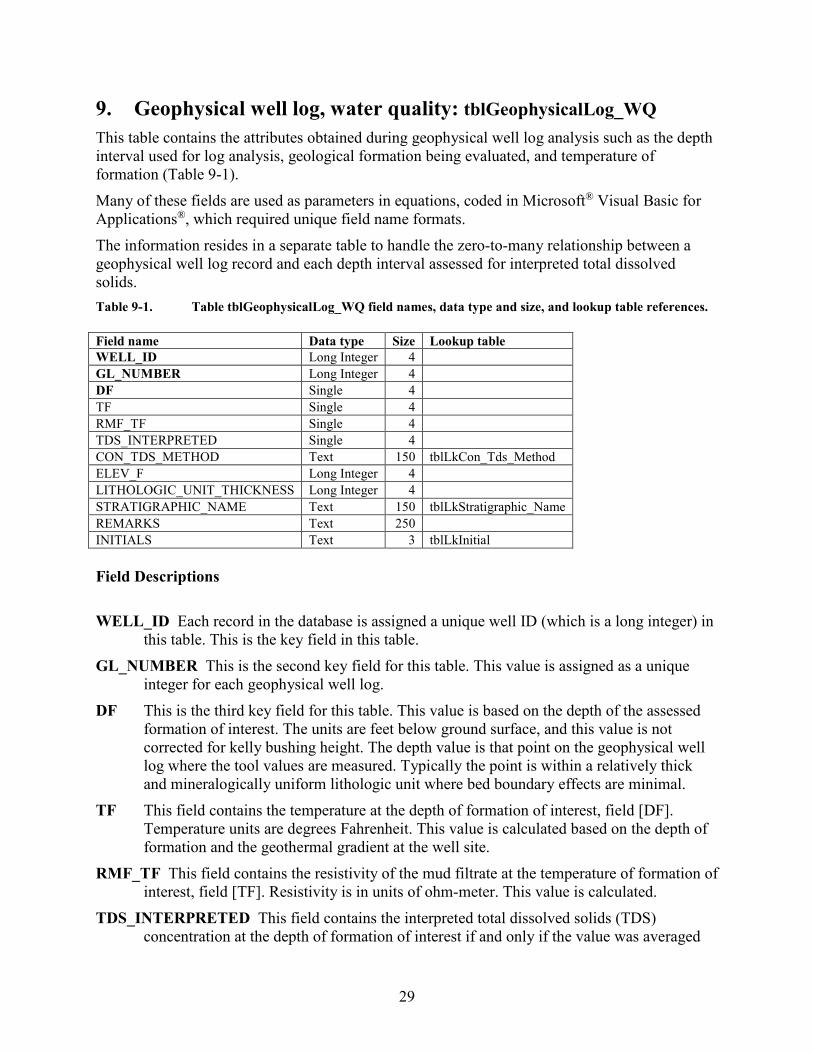
29
9. Geophysical well log, water quality: tblGeophysicalLog_WQ This table contains the attributes obtained during geophysical well log analysis such as the depth interval used for log analysis, geological formation being evaluated, and temperature of formation (Table 9-1). Many of these fields are used as parameters in equations, coded in Microsoft® Visual Basic for Applications®, which required unique field name formats. The information resides in a separate table to handle the zero-to-many relationship between a geophysical well log record and each depth interval assessed for interpreted total dissolved solids. Table 9-1. Table tblGeophysicalLog_WQ field names, data type and size, and lookup table references. Field name Data type Size Lookup table WELL_ID Long Integer 4
GL_NUMBER Long Integer 4
DF Single 4
TF Single 4
RMF_TF Single 4
TDS_INTERPRETED Single 4
CON_TDS_METHOD Text 150 tblLkCon_Tds_Method ELEV_F Long Integer 4
LITHOLOGIC_UNIT_THICKNESS Long Integer 4
STRATIGRAPHIC_NAME Text 150 tblLkStratigraphic_Name REMARKS Text 250
INITIALS Text 3 tblLkInitial Field Descriptions WELL_ID Each record in the database is assigned a unique well ID (which is a long integer) in
this table. This is the key field in this table. GL_NUMBER This is the second key field for this table. This value is assigned as a unique
integer for each geophysical well log. DF This is the third key field for this table. This value is based on the depth of the assessed
formation of interest. The units are feet below ground surface, and this value is not corrected for kelly bushing height. The depth value is that point on the geophysical well log where the tool values are measured. Typically the point is within a relatively thick and mineralogically uniform lithologic unit where bed boundary effects are minimal.
TF This field contains the temperature at the depth of formation of interest, field [DF]. Temperature units are degrees Fahrenheit. This value is calculated based on the depth of formation and the geothermal gradient at the well site.
RMF_TF This field contains the resistivity of the mud filtrate at the temperature of formation of interest, field [TF]. Resistivity is in units of ohm-meter. This value is calculated.
TDS_INTERPRETED This field contains the interpreted total dissolved solids (TDS) concentration at the depth of formation of interest if and only if the value was averaged
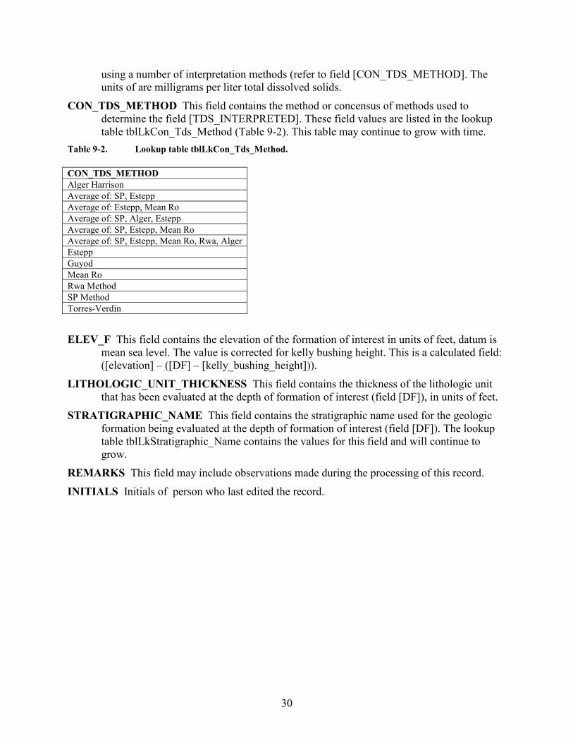
30
using a number of interpretation methods (refer to field [CON_TDS_METHOD]. The units of are milligrams per liter total dissolved solids.
CON_TDS_METHOD This field contains the method or concensus of methods used to determine the field [TDS_INTERPRETED]. These field values are listed in the lookup table tblLkCon_Tds_Method (Table 9-2). This table may continue to grow with time.
Table 9-2. Lookup table tblLkCon_Tds_Method. CON_TDS_METHOD Alger Harrison Average of: SP, Estepp Average of: Estepp, Mean Ro Average of: SP, Alger, Estepp Average of: SP, Estepp, Mean Ro Average of: SP, Estepp, Mean Ro, Rwa, Alger Estepp Guyod Mean Ro Rwa Method SP Method Torres-Verdin ELEV_F This field contains the elevation of the formation of interest in units of feet, datum is
mean sea level. The value is corrected for kelly bushing height. This is a calculated field: ([elevation] – ([DF] – [kelly_bushing_height])).
LITHOLOGIC_UNIT_THICKNESS This field contains the thickness of the lithologic unit that has been evaluated at the depth of formation of interest (field [DF]), in units of feet.
STRATIGRAPHIC_NAME This field contains the stratigraphic name used for the geologic formation being evaluated at the depth of formation of interest (field [DF]). The lookup table tblLkStratigraphic_Name contains the values for this field and will continue to grow.
REMARKS This field may include observations made during the processing of this record. INITIALS Initials of person who last edited the record.
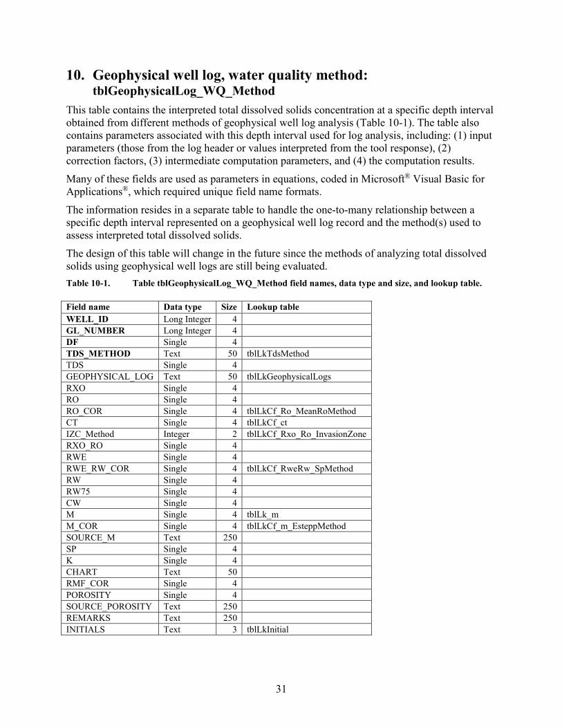
31
10. Geophysical well log, water quality method: tblGeophysicalLog_WQ_Method
This table contains the interpreted total dissolved solids concentration at a specific depth interval obtained from different methods of geophysical well log analysis (Table 10-1). The table also contains parameters associated with this depth interval used for log analysis, including: (1) input parameters (those from the log header or values interpreted from the tool response), (2) correction factors, (3) intermediate computation parameters, and (4) the computation results. Many of these fields are used as parameters in equations, coded in Microsoft® Visual Basic for Applications®, which required unique field name formats. The information resides in a separate table to handle the one-to-many relationship between a specific depth interval represented on a geophysical well log record and the method(s) used to assess interpreted total dissolved solids. The design of this table will change in the future since the methods of analyzing total dissolved solids using geophysical well logs are still being evaluated. Table 10-1. Table tblGeophysicalLog_WQ_Method field names, data type and size, and lookup table. Field name Data type Size Lookup table WELL_ID Long Integer 4
GL_NUMBER Long Integer 4
DF Single 4
TDS_METHOD Text 50 tblLkTdsMethod TDS Single 4
GEOPHYSICAL_LOG Text 50 tblLkGeophysicalLogs RXO Single 4
RO Single 4
RO_COR Single 4 tblLkCf_Ro_MeanRoMethod CT Single 4 tblLkCf_ct IZC_Method Integer 2 tblLkCf_Rxo_Ro_InvasionZone RXO_RO Single 4
RWE Single 4
RWE_RW_COR Single 4 tblLkCf_RweRw_SpMethod RW Single 4
RW75 Single 4
CW Single 4
M Single 4 tblLk_m M_COR Single 4 tblLkCf_m_EsteppMethod SOURCE_M Text 250
SP Single 4
K Single 4
CHART Text 50
RMF_COR Single 4
POROSITY Single 4
SOURCE_POROSITY Text 250
REMARKS Text 250
INITIALS Text 3 tblLkInitial
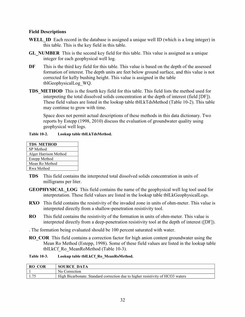
32
Field Descriptions WELL_ID Each record in the database is assigned a unique well ID (which is a long integer) in
this table. This is the key field in this table. GL_NUMBER This is the second key field for this table. This value is assigned as a unique
integer for each geophysical well log. DF This is the third key field for this table. This value is based on the depth of the assessed
formation of interest. The depth units are feet below ground surface, and this value is not corrected for kelly bushing height. This value is assigned in the table tblGeophysicalLog_WQ.
TDS_METHOD This is the fourth key field for this table. This field lists the method used for interpreting the total dissolved solids concentration at the depth of interest (field [DF]). These field values are listed in the lookup table tblLkTdsMethod (Table 10-2). This table may continue to grow with time. Space does not permit actual descriptions of these methods in this data dictionary. Two reports by Estepp (1998, 2010) discuss the evaluation of groundwater quality using geophysical well logs.
Table 10-2. Lookup table tblLkTdsMethod. TDS_METHOD SP Method Alger Harrison Method Estepp Method Mean Ro Method Rwa Method
TDS This field contains the interpreted total dissolved solids concentration in units of milligrams per liter.
GEOPHYSICAL_LOG This field contains the name of the geophysical well log tool used for interpretation. These field values are listed in the lookup table tblLkGeophysicalLogs.
RXO This field contains the resistivity of the invaded zone in units of ohm-meter. This value is interpreted directly from a shallow-penetration resistivity tool.
RO This field contains the resistivity of the formation in units of ohm-meter. This value is interpreted directly from a deep-penetration resistivity tool at the depth of interest ([DF]).
. The formation being evaluated should be 100 percent saturated with water. RO_COR This field contains a correction factor for high anion content groundwater using the
Mean Ro Method (Estepp, 1998). Some of these field values are listed in the lookup table tblLkCf_Ro_MeanRoMethod (Table 10-3).
Table 10-3. Lookup table tblLkCf_Ro_MeanRoMethod. RO_COR SOURCE_DATA 1 No Correction 1.75 High Bicarbonate. Standard correction due to higher resistivity of HCO3 waters
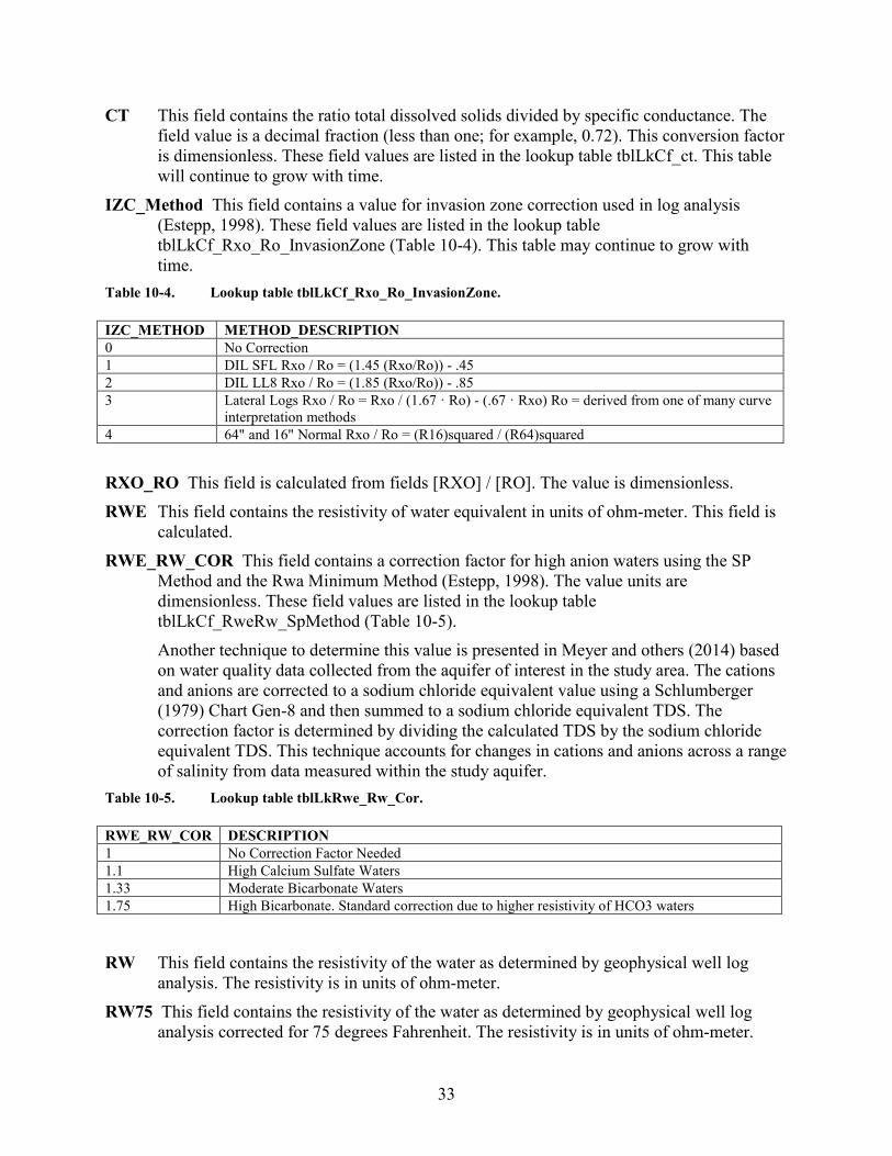
33
CT This field contains the ratio total dissolved solids divided by specific conductance. The field value is a decimal fraction (less than one; for example, 0.72). This conversion factor is dimensionless. These field values are listed in the lookup table tblLkCf_ct. This table will continue to grow with time.
IZC_Method This field contains a value for invasion zone correction used in log analysis (Estepp, 1998). These field values are listed in the lookup table tblLkCf_Rxo_Ro_InvasionZone (Table 10-4). This table may continue to grow with time.
Table 10-4. Lookup table tblLkCf_Rxo_Ro_InvasionZone. IZC_METHOD METHOD_DESCRIPTION 0 No Correction 1 DIL SFL Rxo / Ro = (1.45 (Rxo/Ro)) - .45 2 DIL LL8 Rxo / Ro = (1.85 (Rxo/Ro)) - .85 3 Lateral Logs Rxo / Ro = Rxo / (1.67 · Ro) - (.67 · Rxo) Ro = derived from one of many curve
interpretation methods 4 64" and 16" Normal Rxo / Ro = (R16)squared / (R64)squared RXO_RO This field is calculated from fields [RXO] / [RO]. The value is dimensionless. RWE This field contains the resistivity of water equivalent in units of ohm-meter. This field is
calculated. RWE_RW_COR This field contains a correction factor for high anion waters using the SP
Method and the Rwa Minimum Method (Estepp, 1998). The value units are dimensionless. These field values are listed in the lookup table tblLkCf_RweRw_SpMethod (Table 10-5). Another technique to determine this value is presented in Meyer and others (2014) based on water quality data collected from the aquifer of interest in the study area. The cations and anions are corrected to a sodium chloride equivalent value using a Schlumberger (1979) Chart Gen-8 and then summed to a sodium chloride equivalent TDS. The correction factor is determined by dividing the calculated TDS by the sodium chloride equivalent TDS. This technique accounts for changes in cations and anions across a range of salinity from data measured within the study aquifer.
Table 10-5. Lookup table tblLkRwe_Rw_Cor. RWE_RW_COR DESCRIPTION 1 No Correction Factor Needed 1.1 High Calcium Sulfate Waters 1.33 Moderate Bicarbonate Waters 1.75 High Bicarbonate. Standard correction due to higher resistivity of HCO3 waters
RW This field contains the resistivity of the water as determined by geophysical well log
analysis. The resistivity is in units of ohm-meter. RW75 This field contains the resistivity of the water as determined by geophysical well log
analysis corrected for 75 degrees Fahrenheit. The resistivity is in units of ohm-meter.
34
CW This field contains the conductivity of the water as determined by geophysical well log analysis corrected for 75 degrees Fahrenheit. The resistivity is in units of microsiemens per meter.
M This field contains the cementation exponent. The value is dimensionless. These field values are listed in the lookup table tblLk_m, which also contains the dominant lithology, texture and cement, and report references. This table may continue to grow with time.
M_COR This field contains a correction to the cementation exponent for high anion content. These field values are listed in the lookup table tblLkCf_m_EsteppMethod.
SOURCE_M This field contains a reference to the source of the cementation factor value used in the analysis.
SP This field contains the spontaneous potential (SP) value in units of + or – millivolts. The value is interpreted directly from the spontaneous potential tool at the depth of interest ([DF]).
K This field contains a constant, K, which is dependent on temperature and is used in equations for the SP method (Estepp, 1998).
CHART This field contains a reference to the chart name used for conversion. RMF_COR This field contains the correction factor for resistivity of the mud filtrate when
using the SP method of analysis. POROSITY This field contains the formation porosity value in units of percent total volume as
void in the format of decimal fraction (for example, 0.25). Porosity can be determined from geophysical logs or estimated from other methods.
SOURCE_POROSITY This field contains a reference to the source of the porosity value. REMARKS This field may include observations made during the processing of this record. INITIALS Initials of person who last edited the record.
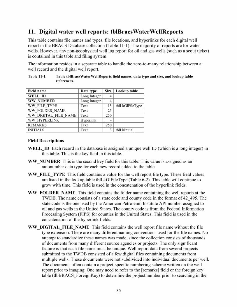
35
11. Digital water well reports: tblBracsWaterWellReports This table contains file names and types, file locations, and hyperlinks for each digital well report in the BRACS Database collection (Table 11-1). The majority of reports are for water wells. However, any non-geophysical well log report for oil and gas wells (such as a scout ticket) is contained in this table and filing system. The information resides in a separate table to handle the zero-to-many relationship between a well record and the digital well report. Table 11-1. Table tblBracsWaterWellReports field names, data type and size, and lookup table
references. Field name Data type Size Lookup table WELL_ID Long Integer 4
WW_NUMBER Long Integer 4
WW_FILE_TYPE Text 15 tblLkGlFileType WW_FOLDER_NAME Text 25
WW_DIGITAL_FILE_NAME Text 250
WW_HYPERLINK Hyperlink -
REMARKS Text 250
INITIALS Text 3 tblLkInitial Field Descriptions WELL_ID Each record in the database is assigned a unique well ID (which is a long integer) in
this table. This is the key field in this table. WW_NUMBER This is the second key field for this table. This value is assigned as an
autonumber data type for each new record added to the table. WW_FILE_TYPE This field contains a value for the well report file type. These field values
are listed in the lookup table tblLkGlFileType (Table 6-2). This table will continue to grow with time. This field is used in the concatenation of the hyperlink fields.
WW_FOLDER_NAME This field contains the folder name containing the well reports at the TWDB. The name consists of a state code and county code in the format of 42_495. The state code is the one used by the American Petroleum Institute API number assigned to oil and gas wells in the United States. The county code is from the Federal Information Processing System (FIPS) for counties in the United States. This field is used in the concatenation of the hyperlink fields.
WW_DIGITAL_FILE_NAME This field contains the well report file name without the file type extension. There are many different naming conventions used for the file names. No attempt to standardize these names was made, since the collection consists of thousands of documents from many different source agencies or projects. The only significant feature is that each file name must be unique. Well report data from several projects submitted to the TWDB consisted of a few digital files containing documents from multiple wells. These documents were not subdivided into individual documents per well. The documents often contain a project-specific numbering scheme written on the well report prior to imaging. One may need to refer to the [remarks] field or the foreign key table (tlbBRACS_ForeignKey) to determine the project number prior to searching in the
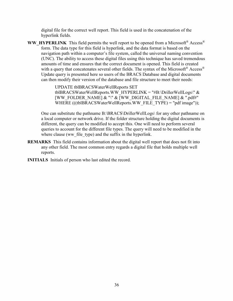
36
digital file for the correct well report. This field is used in the concatenation of the hyperlink fields.
WW_HYPERLINK This field permits the well report to be opened from a Microsoft® Access® form. The data type for this field is hyperlink, and the data format is based on the navigation path within a computer’s file system, called the universal naming convention (UNC). The ability to access these digital files using this technique has saved tremendous amounts of time and ensures that the correct document is opened. This field is created with a query that concatenates several other fields. The syntax of the Microsoft® Access® Update query is presented here so users of the BRACS Database and digital documents can then modify their version of the database and file structure to meet their needs:
UPDATE tblBRACSWaterWellReports SET tblBRACSWaterWellReports.WW_HYPERLINK = "#B:\DrillerWellLogs\" & [WW_FOLDER_NAME] & "\" & [WW_DIGITAL_FILE_NAME] & ".pdf#" WHERE (((tblBRACSWaterWellReports.WW_FILE_TYPE) = "pdf image"));
One can substitute the pathname B:\BRACS\DrillerWellLogs\ for any other pathname on a local computer or network drive. If the folder structure holding the digital documents is different, the query can be modified to accept this. One will need to perform several queries to account for the different file types. The query will need to be modified in the where clause (ww_file_type) and the suffix in the hyperlink.
REMARKS This field contains information about the digital well report that does not fit into any other field. The most common entry regards a digital file that holds multiple well reports.
INITIALS Initials of person who last edited the record.
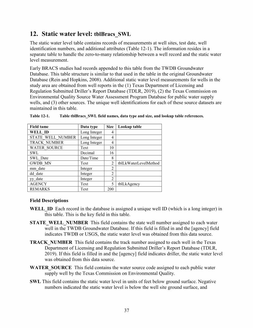
37
12. Static water level: tblBracs_SWL The static water level table contains records of measurements at well sites, test date, well identification numbers, and additional attributes (Table 12-1). The information resides in a separate table to handle the zero-to-many relationship between a well record and the static water level measurement. Early BRACS studies had records appended to this table from the TWDB Groundwater Database. This table structure is similar to that used in the table in the original Groundwater Database (Rein and Hopkins, 2008). Additional static water level measurements for wells in the study area are obtained from well reports in the (1) Texas Department of Licensing and Regulation Submitted Driller’s Report Database (TDLR, 2019), (2) the Texas Commission on Environmental Quality Source Water Assessment Program Database for public water supply wells, and (3) other sources. The unique well identifications for each of these source datasets are maintained in this table. Table 12-1. Table tblBracs_SWL field names, data type and size, and lookup table references. Field tame Data type Size Lookup table WELL_ID Long Integer 4
STATE_WELL_NUMBER Long Integer 4
TRACK_NUMBER Long Integer 4
WATER_SOURCE Text 10
SWL Decimal 16
SWL_Date Date/Time 8
GWDB_MN Text 2 tblLkWaterLevelMethod mm_date Integer 2
dd_date Integer 2
yy_date Integer 2
AGENCY Text 5 tblLkAgency REMARKS Text 200
Field Descriptions WELL_ID Each record in the database is assigned a unique well ID (which is a long integer) in
this table. This is the key field in this table. STATE_WELL_NUMBER This field contains the state well number assigned to each water
well in the TWDB Groundwater Database. If this field is filled in and the [agency] field indicates TWDB or USGS, the static water level was obtained from this data source.
TRACK_NUMBER This field contains the track number assigned to each well in the Texas Department of Licensing and Regulation Submitted Driller’s Report Database (TDLR, 2019). If this field is filled in and the [agency] field indicates driller, the static water level was obtained from this data source.
WATER_SOURCE This field contains the water source code assigned to each public water supply well by the Texas Commission on Environmental Quality.
SWL This field contains the static water level in units of feet below ground surface. Negative numbers indicated the static water level is below the well site ground surface, and
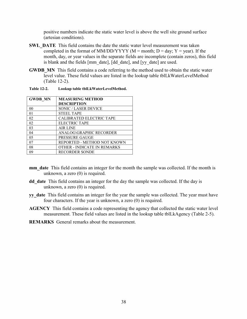
38
positive numbers indicate the static water level is above the well site ground surface (artesian conditions).
SWL_DATE This field contains the date the static water level measurement was taken completed in the format of MM/DD/YYYY (M = month; D = day; Y = year). If the month, day, or year values in the separate fields are incomplete (contain zeros), this field is blank and the fields [mm_date], [dd_date], and [yy_date] are used.
GWDB_MN This field contains a code referring to the method used to obtain the static water level value. These field values are listed in the lookup table tblLkWaterLevelMethod (Table 12-2).
Table 12-2. Lookup table tblLkWaterLevelMethod. GWDB_MN MEASURING METHOD
DESCRIPTION 00 SONIC / LASER DEVICE 01 STEEL TAPE 02 CALIBRATED ELECTRIC TAPE 02 ELECTRIC TAPE 03 AIR LINE 04 ANALOG\GRAPHIC RECORDER 05 PRESSURE GAUGE 07 REPORTED - METHOD NOT KNOWN 08 OTHER - INDICATE IN REMARKS 09 RECORDER SONDE
mm_date This field contains an integer for the month the sample was collected. If the month is
unknown, a zero (0) is required. dd_date This field contains an integer for the day the sample was collected. If the day is
unknown, a zero (0) is required. yy_date This field contains an integer for the year the sample was collected. The year must have
four characters. If the year is unknown, a zero (0) is required. AGENCY This field contains a code representing the agency that collected the static water level
measurement. These field values are listed in the lookup table tblLkAgency (Table 2-5). REMARKS General remarks about the measurement.
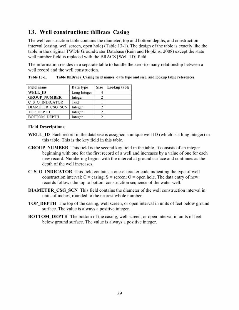
39
13. Well construction: tblBracs_Casing The well construction table contains the diameter, top and bottom depths, and construction interval (casing, well screen, open hole) (Table 13-1). The design of the table is exactly like the table in the original TWDB Groundwater Database (Rein and Hopkins, 2008) except the state well number field is replaced with the BRACS [Well_ID] field. The information resides in a separate table to handle the zero-to-many relationship between a well record and the well construction. Table 13-1. Table tblBracs_Casing field names, data type and size, and lookup table references. Field name Data type Size Lookup table WELL_ID Long Integer 4
GROUP_NUMBER Integer 2
C_S_O_INDICATOR Text 1
DIAMETER_CSG_SCN Integer 2
TOP_DEPTH Integer 2
BOTTOM_DEPTH Integer 2
Field Descriptions WELL_ID Each record in the database is assigned a unique well ID (which is a long integer) in
this table. This is the key field in this table. GROUP_NUMBER This field is the second key field in the table. It consists of an integer
beginning with one for the first record of a well and increases by a value of one for each new record. Numbering begins with the interval at ground surface and continues as the depth of the well increases.
C_S_O_INDICATOR This field contains a one-character code indicating the type of well construction interval: C = casing; S = screen; O = open hole. The data entry of new records follows the top to bottom construction sequence of the water well.
DIAMETER_CSG_SCN This field contains the diameter of the well construction interval in units of inches, rounded to the nearest whole number.
TOP_DEPTH The top of the casing, well screen, or open interval in units of feet below ground surface. The value is always a positive integer.
BOTTOM_DEPTH The bottom of the casing, well screen, or open interval in units of feet below ground surface. The value is always a positive integer.
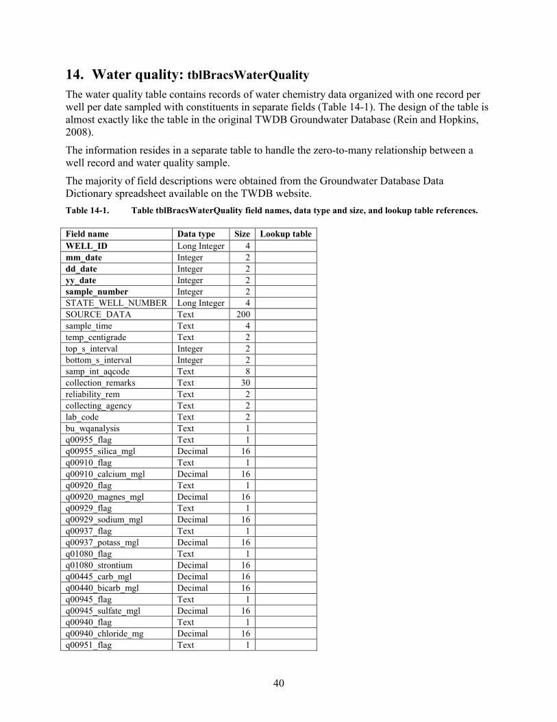
40
14. Water quality: tblBracsWaterQuality The water quality table contains records of water chemistry data organized with one record per well per date sampled with constituents in separate fields (Table 14-1). The design of the table is almost exactly like the table in the original TWDB Groundwater Database (Rein and Hopkins, 2008). The information resides in a separate table to handle the zero-to-many relationship between a well record and water quality sample. The majority of field descriptions were obtained from the Groundwater Database Data Dictionary spreadsheet available on the TWDB website. Table 14-1. Table tblBracsWaterQuality field names, data type and size, and lookup table references. Field name Data type Size Lookup table WELL_ID Long Integer 4
mm_date Integer 2
dd_date Integer 2
yy_date Integer 2
sample_number Integer 2
STATE_WELL_NUMBER Long Integer 4
SOURCE_DATA Text 200
sample_time Text 4
temp_centigrade Text 2
top_s_interval Integer 2
bottom_s_interval Integer 2
samp_int_aqcode Text 8
collection_remarks Text 30
reliability_rem Text 2
collecting_agency Text 2
lab_code Text 2
bu_wqanalysis Text 1
q00955_flag Text 1
q00955_silica_mgl Decimal 16
q00910_flag Text 1
q00910_calcium_mgl Decimal 16
q00920_flag Text 1
q00920_magnes_mgl Decimal 16
q00929_flag Text 1
q00929_sodium_mgl Decimal 16
q00937_flag Text 1
q00937_potass_mgl Decimal 16
q01080_flag Text 1
q01080_strontium Decimal 16
q00445_carb_mgl Decimal 16
q00440_bicarb_mgl Decimal 16
q00945_flag Text 1
q00945_sulfate_mgl Decimal 16
q00940_flag Text 1
q00940_chloride_mg Decimal 16
q00951_flag Text 1
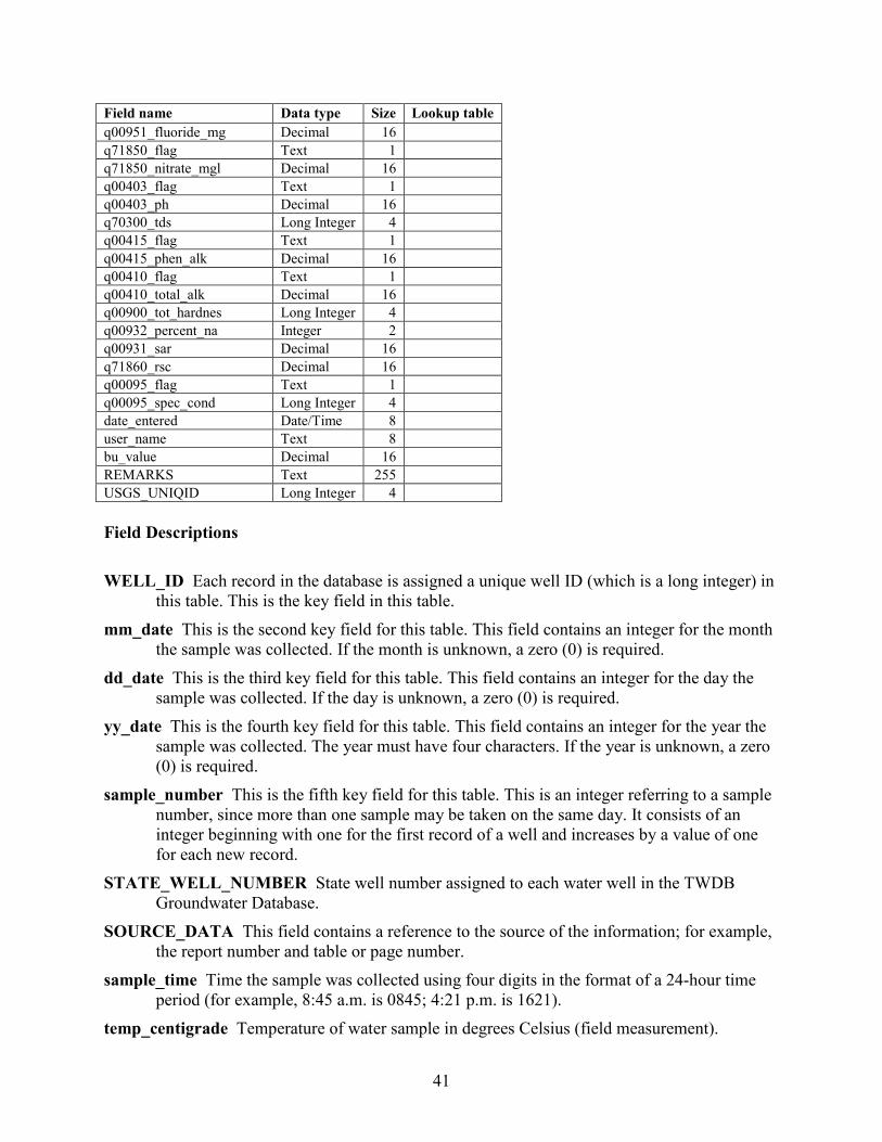
41
Field name Data type Size Lookup table q00951_fluoride_mg Decimal 16
q71850_flag Text 1
q71850_nitrate_mgl Decimal 16
q00403_flag Text 1
q00403_ph Decimal 16
q70300_tds Long Integer 4
q00415_flag Text 1
q00415_phen_alk Decimal 16
q00410_flag Text 1
q00410_total_alk Decimal 16
q00900_tot_hardnes Long Integer 4
q00932_percent_na Integer 2
q00931_sar Decimal 16
q71860_rsc Decimal 16
q00095_flag Text 1
q00095_spec_cond Long Integer 4
date_entered Date/Time 8
user_name Text 8
bu_value Decimal 16
REMARKS Text 255 USGS_UNIQID Long Integer 4 Field Descriptions WELL_ID Each record in the database is assigned a unique well ID (which is a long integer) in
this table. This is the key field in this table. mm_date This is the second key field for this table. This field contains an integer for the month
the sample was collected. If the month is unknown, a zero (0) is required. dd_date This is the third key field for this table. This field contains an integer for the day the
sample was collected. If the day is unknown, a zero (0) is required. yy_date This is the fourth key field for this table. This field contains an integer for the year the
sample was collected. The year must have four characters. If the year is unknown, a zero (0) is required.
sample_number This is the fifth key field for this table. This is an integer referring to a sample number, since more than one sample may be taken on the same day. It consists of an integer beginning with one for the first record of a well and increases by a value of one for each new record.
STATE_WELL_NUMBER State well number assigned to each water well in the TWDB Groundwater Database.
SOURCE_DATA This field contains a reference to the source of the information; for example, the report number and table or page number.
sample_time Time the sample was collected using four digits in the format of a 24-hour time period (for example, 8:45 a.m. is 0845; 4:21 p.m. is 1621).
temp_centigrade Temperature of water sample in degrees Celsius (field measurement).
42
top_s_interval Top interval of formation where sample was collected in units of feet below ground surface (only for multiple completion wells).
bottom_s_interval Bottom interval of formation where sample was collected in units of feet below ground surface (only for multiple completion wells).
samp_int_aqcode Aquifer code for the sampled interval (only for multiple completion wells). collection_remarks Remarks about the sample collected. reliability_rem Indicates the process used to collect the sample. collecting_agency Identifies the entity that collected the sample. lab_code Identifies the lab used to analyze the sample. bu_wqanalysis Indicates whether the analysis of the sample is Balanced (B) or Unbalanced (U). q00955_flag Used to identify constituent concentrations below the lab's detection limits. q00955_silica_mgl Silica, dissolved, in units of milligrams per liter. q00910_flag Used to identify constituent concentrations below the lab's detection limits. q00910_calcium_mgl Calcium, dissolved, in units of milligrams per liter. q00920_flag Used to identify constituent concentrations below the lab's detection limits. q00920_magnes_mgl Magnesium, dissolved, in units of milligrams per liter. q00929_flag Used to identify constituent concentrations below the lab's detection limits. q00929_sodium_mgl Sodium, dissolved, in units of milligrams per liter. q00937_flag Used to identify constituent concentrations below the lab's detection limits. q00937_potass_mgl Potassium, dissolved, in units of milligrams per liter. q01080_flag Used to identify constituent concentrations below the lab's detection limits. q01080_strontium Strontium, dissolved, in units of milligrams per liter. q00445_carb_mgl Carbonate, dissolved, in units of milligrams per liter. q00440_bicarb_mgl Bicarbonate, dissolved, in units of milligrams per liter. q00945_flag Used to identify constituent concentrations below the lab's detection limits. q00945_sulfate_mgl Sulfate, dissolved, in units of milligrams per liter. q00940_flag Used to identify constituent concentrations below the lab's detection limits. q00940_chloride_mg Chloride, dissolved, in units of milligrams per liter. q00951_flag Used to identify constituent concentrations below the lab's detection limits. q00951_fluoride_mg Fluoride, dissolved, in units of milligrams per liter. q71850_flag Used to identify constituent concentrations below the lab's detection limits. q71850_nitrate_mgl Nitrate nitrogen, dissolved, in units of milligrams per liter. q00403_flag Used to identify constituent concentrations below the lab's detection limits.
43
q00403_ph pH, standard units (field measurement). q70300_tds Total dissolved solids, dissolved, sum of constituents, in units of milligrams per
liter. q00415_flag Used to identify constituent concentrations below the lab's detection limits. q00415_phen_alk Phenol alkalinity. q00410_flag Used to identify constituent concentrations below the lab's detection limits. q00410_total_alk Total alkalinity, dissolved (analyzed in lab). q00900_tot_hardnes Total hardness. q00932_percent_na Percent sodium. q00931_sar Sodium absorption ratio. q71860_rsc Residual sodium carbonate. q00095_flag Used to identify constituent concentrations below the lab's detection limits. q00095_spec_cond Specific conductance, in units of micromhos per centimeter (microsiemens
per centimeter) at 25 degrees Celsius (field measurement). date_entered This field contains the date the record was last edited. user_name User name of person who last edited the record. bu_value Value of the balanced/unbalanced equation. Units in percent (for example, 3.5). REMARKS General remarks about an analysis. USGS_UNIQID Unique id assigned to each produced water sample found within the U.S.
Geological Survey Produced Water Database (Blondes and others, 2016). These samples are from the saline water co-produced with oil and gas.
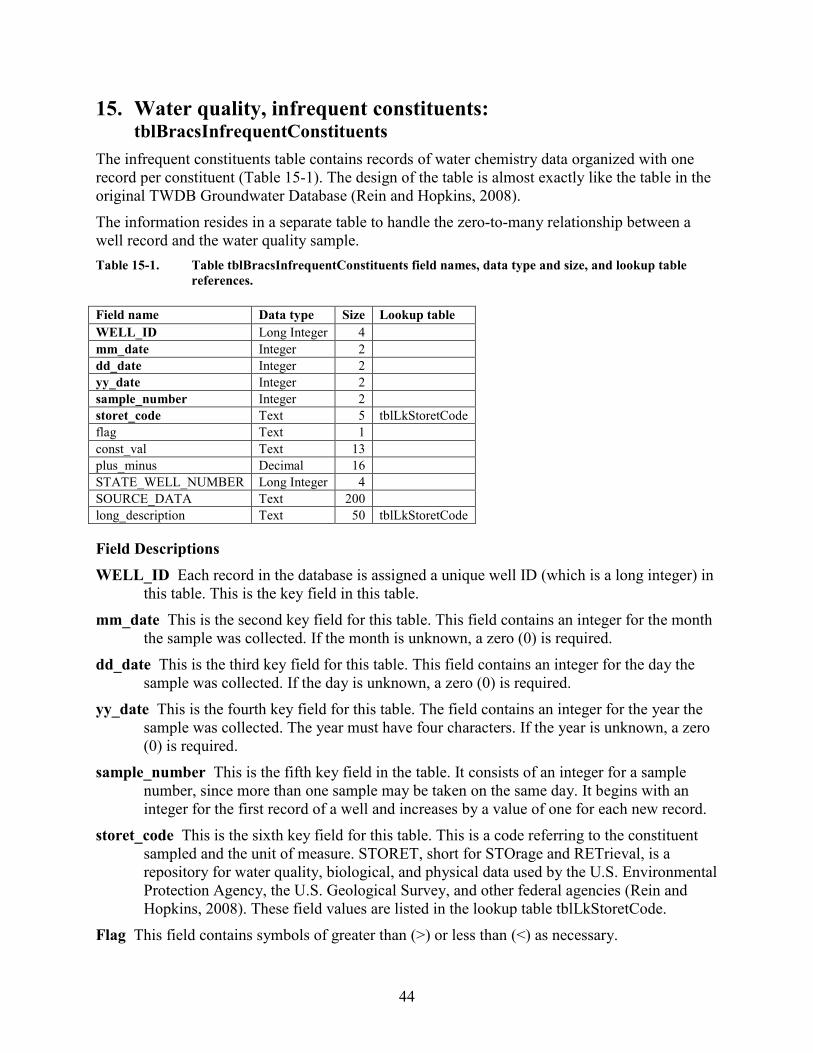
44
15. Water quality, infrequent constituents: tblBracsInfrequentConstituents
The infrequent constituents table contains records of water chemistry data organized with one record per constituent (Table 15-1). The design of the table is almost exactly like the table in the original TWDB Groundwater Database (Rein and Hopkins, 2008). The information resides in a separate table to handle the zero-to-many relationship between a well record and the water quality sample. Table 15-1. Table tblBracsInfrequentConstituents field names, data type and size, and lookup table
references. Field name Data type Size Lookup table WELL_ID Long Integer 4
mm_date Integer 2
dd_date Integer 2
yy_date Integer 2
sample_number Integer 2
storet_code Text 5 tblLkStoretCode flag Text 1
const_val Text 13
plus_minus Decimal 16
STATE_WELL_NUMBER Long Integer 4
SOURCE_DATA Text 200
long_description Text 50 tblLkStoretCode Field Descriptions WELL_ID Each record in the database is assigned a unique well ID (which is a long integer) in
this table. This is the key field in this table. mm_date This is the second key field for this table. This field contains an integer for the month
the sample was collected. If the month is unknown, a zero (0) is required. dd_date This is the third key field for this table. This field contains an integer for the day the
sample was collected. If the day is unknown, a zero (0) is required. yy_date This is the fourth key field for this table. The field contains an integer for the year the
sample was collected. The year must have four characters. If the year is unknown, a zero (0) is required.
sample_number This is the fifth key field in the table. It consists of an integer for a sample number, since more than one sample may be taken on the same day. It begins with an integer for the first record of a well and increases by a value of one for each new record.
storet_code This is the sixth key field for this table. This is a code referring to the constituent sampled and the unit of measure. STORET, short for STOrage and RETrieval, is a repository for water quality, biological, and physical data used by the U.S. Environmental Protection Agency, the U.S. Geological Survey, and other federal agencies (Rein and Hopkins, 2008). These field values are listed in the lookup table tblLkStoretCode.
Flag This field contains symbols of greater than (>) or less than (<) as necessary.
45
const_val This field contains the constituent value. plus_minus This field contains a number referring to the accuracy of the constituent value plus
or minus. Usually associated with radioactive constituents. STATE_WELL_NUMBER State well number assigned to each water well in the TWDB
Groundwater Database. SOURCE_DATA This field contains a reference to the source of the information; for example,
the report number and table or page number. LONG_DESCRIPTION This field contains the STORET code long description, from lookup
table tblLkStoretCode.
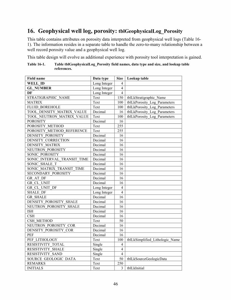
46
16. Geophysical well log, porosity: tblGeophysicalLog_Porosity This table contains attributes on porosity data interpreted from geophysical well logs (Table 16-1). The information resides in a separate table to handle the zero-to-many relationship between a well record porosity value and a geophysical well log. This table design will evolve as additional experience with porosity tool interpretation is gained. Table 16-1. Table tblGeophysicalLog_Porosity field names, data type and size, and lookup table
references. Field name Data type Size Lookup table WELL_ID Long Integer 4
GL_NUMBER Long Integer 4
DF Long Integer 4 STRATIGRAPHIC_NAME Text 150 tblLkStratigraphic_Name MATRIX Text 100 tblLkPorosity_Log_Parameters FLUID_BOREHOLE Text 100 tblLkPorosity_Log_Parameters TOOL_DENSITY_MATRIX_VALUE Decimal 16 tblLkPorosity_Log_Parameters TOOL_NEUTRON_MATRIX_VALUE Text 100 tblLkPorosity_Log_Parameters POROSITY Decimal 16 POROSITY_METHOD Text 255 POROSITY_METHOD_REFERENCE Text 255 DENSITY_POROSITY Decimal 16 DENSITY_CORRECTION Decimal 16 DENSITY_MATRIX Decimal 16 NEUTRON_POROSITY Decimal 16 SONIC_POROSITY Decimal 16 SONIC_INTERVAL_TRANSIT_TIME Decimal 16 SONIC_SHALE_T Decimal 16 SONIC_MATRIX_TRANSIT_TIME Decimal 16 SECONDARY_POROSITY Decimal 16 GR_AT_DF Decimal 16 GR_CL_UNIT Decimal 16 GR_CL_UNIT_DF Long Integer 4 SHALE_DF Long Integer 4 GR_SHALE Decimal 16 DENSITY_POROSITY_SHALE Decimal 16 NEUTRON_POROSITY_SHALE Decimal 16 ISH Decimal 16 CSH Decimal 16 CSH_METHOD Text 50 NEUTRON_POROSITY_COR Decimal 16 DENSITY_POROSITY_COR Decimal 16 PEF Decimal 16 PEF_LITHOLOGY Text 100 tblLkSimplified_Lithologic_Name RESISTIVITY_TOTAL Single 4 RESISTIVITY_SHALE Single 4 RESISTIVITY_SAND Single 4 SOURCE_GEOLOGIC_DATA Text 50 tblLkSourceGeologicData REMARKS Text 250
INITIALS Text 3 tblLkInitial
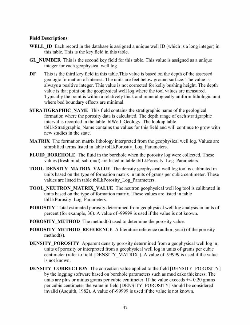
47
Field Descriptions WELL_ID Each record in the database is assigned a unique well ID (which is a long integer) in
this table. This is the key field in this table. GL_NUMBER This is the second key field for this table. This value is assigned as a unique
integer for each geophysical well log. DF This is the third key field in this table.This value is based on the depth of the assessed
geologic formation of interest. The units are feet below ground surface. The value is always a positive integer. This value is not corrected for kelly bushing height. The depth value is that point on the geophysical well log where the tool values are measured. Typically the point is within a relatively thick and mineralogically uniform lithologic unit where bed boundary effects are minimal.
STRATIGRAPHIC_NAME This field contains the stratigraphic name of the geological formation where the porosity data is calculated. The depth range of each stratigraphic interval is recorded in the table tblWell_Geology. The lookup table tblLkStratigraphic_Name contains the values for this field and will continue to grow with new studies in the state.
MATRIX The formation matrix lithology interpreted from the geophysical well log. Values are simplified terms listed in table tblLkPorosity_Log_Parameters.
FLUID_BOREHOLE The fluid in the borehole when the porosity log were collected. These values (fresh mud; salt mud) are listed in table tblLkPorosity_Log_Parameters.
TOOL_DENSITY_MATRIX_VALUE The density geophysical well log tool is calibrated in units based on the type of formation matrix in units of grams per cubic centimeter. These values are listed in table tblLkPorosity_Log_Parameters.
TOOL_NEUTRON_MATRIX_VALUE The neutron geophysical well log tool is calibrated in units based on the type of formation matrix. These values are listed in table tblLkPorosity_Log_Parameters.
POROSITY Total estimated porosity determined from geophysical well log analysis in units of percent (for example, 36). A value of -99999 is used if the value is not known.
POROSITY_METHOD The method(s) used to determine the porosity value. POROSITY_METHOD_REFERENCE A literature reference (author, year) of the porosity
method(s). DENSITY_POROSITY Apparent density porosity determined from a geophysical well log in
units of porosity or interpreted from a geophysical well log in units of grams per cubic centimeter (refer to field [DENSITY_MATRIX]). A value of -99999 is used if the value is not known.
DENSITY_CORRECTION The correction value applied to the field [DENSITY_POROSITY] by the logging software based on borehole parameters such as mud cake thickness. The units are plus or minus grams per cubic centimeter. If the value exceeds +/- 0.20 grams per cubic centimeter the value in field [DENSITY_POROSITY] should be considered invalid (Asquith, 1982). A value of -99999 is used if the value is not known.
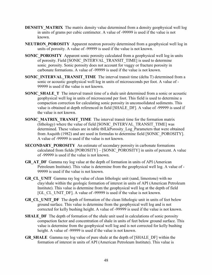
48
DENSITY_MATRIX The matrix density value determined from a density geophysical well log in units of grams per cubic centimeter. A value of -99999 is used if the value is not known.
NEUTRON_POROSITY Apparent neutron porosity determined from a geophysical well log in units of porosity. A value of -99999 is used if the value is not known.
SONIC_POROSITY Apparent sonic porosity calculated from a geophysical well log in units of porosity. Field [SONIC_INTERVAL_TRANSIT_TIME] is used to determine sonic_porosity. Sonic porosity does not account for vuggy or fracture porosity in carbonate formations. A value of -99999 is used if the value is not known.
SONIC_INTERVAL_TRANSIT_TIME The interval transit time (delta T) determined from a sonic or acoustic geophysical well log in units of microseconds per foot. A value of -99999 is used if the value is not known.
SONIC_SHALE_T The interval transit time of a shale unit determined from a sonic or acoustic geophysical well log in units of microsecond per foot. This field is used to determine a compaction correction for calculating sonic porosity in unconsolidated sediments. This value is obtained at depth referenced in field [SHALE_DF]. A value of -99999 is used if the value is not known.
SONIC_MATRIX_TRANSIT_TIME The interval transit time for the formation matrix (lithology) where the value of field [SONIC_INTERVAL_TRANSIT_TIME] was determined. These values are in table tblLkPorosity_Log_Parameters that were obtained from Asquith (1982) and are used in formulas to determine field [SONIC_POROSITY]. A value of -99999 is used if the value is not known.
SECONDARY_POROSITY An estimate of secondary porosity in carbonate formations calculated from fields [POROSITY] – [SONIC_POROSITY] in units of percent. A value of -99999 is used if the value is not known.
GR_AT_DF Gamma ray log value at the depth of formation in units of API (American Petroleum Institute). This value is determine from the geophysical well log. A value of -99999 is used if the value is not known.
GR_CL_UNIT Gamma ray log value of clean lithologic unit (sand, limestone) with no clay/shale within the geologic formation of interest in units of API (American Petroleum Institute). This value is determine from the geophysical well log at the depth of field [GL_CL_UNIT_DF]. A value of -99999 is used if the value is not known.
GR_CL_UNIT_DF The depth of formation of the clean lithologic unit in units of feet below ground surface. This value is determine from the geophysical well log and is not corrected for kelly bushing height. A value of -99999 is used if the value is not known.
SHALE_DF The depth of formation of the shale unit used in calculations of sonic porosity compaction factor and concentration of shale in units of feet below ground surface. This value is determine from the geophysical well log and is not corrected for kelly bushing height. A value of -99999 is used if the value is not known.
GR_SHALE Gamma ray log value of pure shale at the depth of [SHALE_DF] within the formation of interest in units of API (American Petroleum Institute). This value is
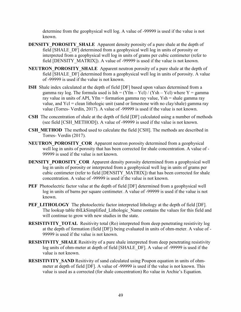
49
determine from the geophysical well log. A value of -99999 is used if the value is not known.
DENSITY_POROSITY_SHALE Apparent density porosity of a pure shale at the depth of field [SHALE_DF] determined from a geophysical well log in units of porosity or interpreted from a geophysical well log in units of grams per cubic centimeter (refer to field [DENSITY_MATRIX]). A value of -99999 is used if the value is not known.
NEUTRON_POROSITY_SHALE Apparent neutron porosity of a pure shale at the depth of field [SHALE_DF] determined from a geophysical well log in units of porosity. A value of -99999 is used if the value is not known.
ISH Shale index calculated at the depth of field [DF] based upon values determined from a gamma ray log. The formula used is Ish = (Yfm – Ycl) / (Ysh – Ycl) where Y = gamma ray value in units of API, Yfm = formation gamma ray value, Ysh = shale gamma ray value, and Ycl = clean lithologic unit (sand or limestone with no clay/shale) gamma ray value (Torres- Verdín, 2017). A value of -99999 is used if the value is not known.
CSH The concentration of shale at the depth of field [DF] calculated using a number of methods (see field [CSH_METHOD]). A value of -99999 is used if the value is not known.
CSH_METHOD The method used to calculate the field [CSH]. The methods are described in Torres- Verdín (2017).
NEUTRON_POROSITY_COR Apparent neutron porosity determined from a geophysical well log in units of porosity that has been corrected for shale concentration. A value of -99999 is used if the value is not known.
DENSITY_POROSITY_COR Apparent density porosity determined from a geophysical well log in units of porosity or interpreted from a geophysical well log in units of grams per cubic centimeter (refer to field [DENSITY_MATRIX]) that has been corrected for shale concentration. A value of -99999 is used if the value is not known.
PEF Photoelectric factor value at the depth of field [DF] determined from a geophysical well log in units of barns per square centimeter. A value of -99999 is used if the value is not known.
PEF_LITHOLOGY The photoelectric factor interpreted lithology at the depth of field [DF]. The lookup table tblLkSimplified_Lithologic_Name contains the values for this field and will continue to grow with new studies in the state.
RESISTIVITY_TOTAL Resitivity total (Ro) interpreted from deep penetrating resistivity log at the depth of formation (field [DF]) being evaluated in units of ohm-meter. A value of -99999 is used if the value is not known.
RESISTIVITY_SHALE Resitivity of a pure shale interpreted from deep penetrating resistivity log units of ohm-meter at depth of field [SHALE_DF]. A value of -99999 is used if the value is not known.
RESISTIVITY_SAND Resitivity of sand calculated using Poupon equation in units of ohm-meter at depth of field [DF]. A value of -99999 is used if the value is not known. This value is used as a corrected (for shale concentration) Ro value in Archie’s Equation.
50
Requires the additional inputs of shale concentration (field [CSH]) and shale resistivity (field [RESISTIVITY_SHALE]).
SOURCE_GEOLOGIC_DATA Each record is assigned the source of the porosity information. These field values are listed in the lookup table tblLkSourceGeologicData (Table 4-5). The table will continue to grow with time as new sources of information are acquired, and Table 4-5 contains only a partial list of these values.
REMARKS This field may include additional information about the porosity value or method. This field may also contain a reference to the contracted study that provided the data.
INITIALS Initials of person who last edited the record.
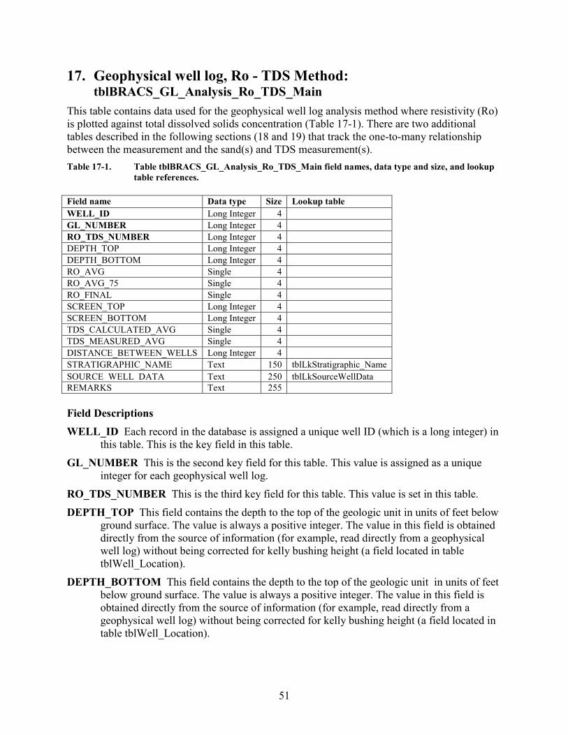
51
17. Geophysical well log, Ro - TDS Method: tblBRACS_GL_Analysis_Ro_TDS_Main
This table contains data used for the geophysical well log analysis method where resistivity (Ro) is plotted against total dissolved solids concentration (Table 17-1). There are two additional tables described in the following sections (18 and 19) that track the one-to-many relationship between the measurement and the sand(s) and TDS measurement(s). Table 17-1. Table tblBRACS_GL_Analysis_Ro_TDS_Main field names, data type and size, and lookup
table references. Field name Data type Size Lookup table WELL_ID Long Integer 4
GL_NUMBER Long Integer 4
RO_TDS_NUMBER Long Integer 4 DEPTH_TOP Long Integer 4 DEPTH_BOTTOM Long Integer 4 RO_AVG Single 4 RO_AVG_75 Single 4 RO_FINAL Single 4 SCREEN_TOP Long Integer 4 SCREEN_BOTTOM Long Integer 4 TDS_CALCULATED_AVG Single 4 TDS_MEASURED_AVG Single 4 DISTANCE_BETWEEN_WELLS Long Integer 4 STRATIGRAPHIC_NAME Text 150 tblLkStratigraphic_Name SOURCE_WELL_DATA Text 250 tblLkSourceWellData REMARKS Text 255 Field Descriptions WELL_ID Each record in the database is assigned a unique well ID (which is a long integer) in
this table. This is the key field in this table. GL_NUMBER This is the second key field for this table. This value is assigned as a unique
integer for each geophysical well log. RO_TDS_NUMBER This is the third key field for this table. This value is set in this table. DEPTH_TOP This field contains the depth to the top of the geologic unit in units of feet below
ground surface. The value is always a positive integer. The value in this field is obtained directly from the source of information (for example, read directly from a geophysical well log) without being corrected for kelly bushing height (a field located in table tblWell_Location).
DEPTH_BOTTOM This field contains the depth to the top of the geologic unit in units of feet below ground surface. The value is always a positive integer. The value in this field is obtained directly from the source of information (for example, read directly from a geophysical well log) without being corrected for kelly bushing height (a field located in table tblWell_Location).
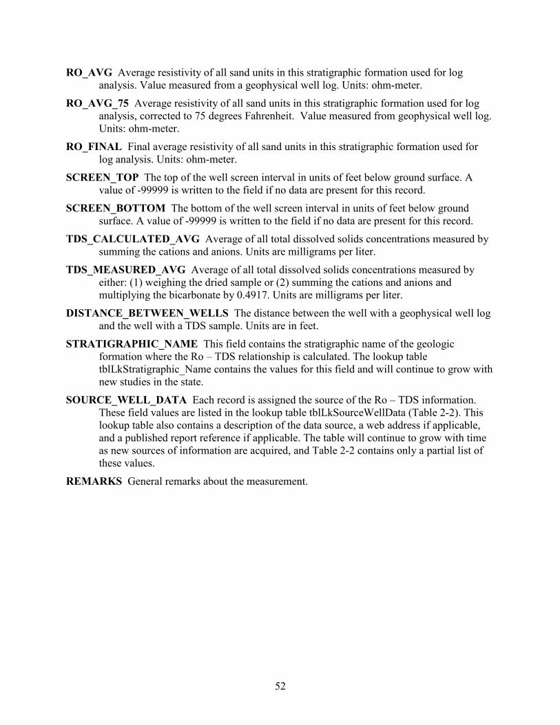
52
RO_AVG Average resistivity of all sand units in this stratigraphic formation used for log analysis. Value measured from a geophysical well log. Units: ohm-meter.
RO_AVG_75 Average resistivity of all sand units in this stratigraphic formation used for log analysis, corrected to 75 degrees Fahrenheit. Value measured from geophysical well log. Units: ohm-meter.
RO_FINAL Final average resistivity of all sand units in this stratigraphic formation used for log analysis. Units: ohm-meter.
SCREEN_TOP The top of the well screen interval in units of feet below ground surface. A value of -99999 is written to the field if no data are present for this record.
SCREEN_BOTTOM The bottom of the well screen interval in units of feet below ground surface. A value of -99999 is written to the field if no data are present for this record.
TDS_CALCULATED_AVG Average of all total dissolved solids concentrations measured by summing the cations and anions. Units are milligrams per liter.
TDS_MEASURED_AVG Average of all total dissolved solids concentrations measured by either: (1) weighing the dried sample or (2) summing the cations and anions and multiplying the bicarbonate by 0.4917. Units are milligrams per liter.
DISTANCE_BETWEEN_WELLS The distance between the well with a geophysical well log and the well with a TDS sample. Units are in feet.
STRATIGRAPHIC_NAME This field contains the stratigraphic name of the geologic formation where the Ro – TDS relationship is calculated. The lookup table tblLkStratigraphic_Name contains the values for this field and will continue to grow with new studies in the state.
SOURCE_WELL_DATA Each record is assigned the source of the Ro – TDS information. These field values are listed in the lookup table tblLkSourceWellData (Table 2-2). This lookup table also contains a description of the data source, a web address if applicable, and a published report reference if applicable. The table will continue to grow with time as new sources of information are acquired, and Table 2-2 contains only a partial list of these values.
REMARKS General remarks about the measurement.
53
18. Geophysical well log, Ro sands: tblBRACS_GL_Analysis_Ro_Sands This table contains data used for the geophysical well log analysis method where resistivity (Ro) is plotted against total dissolved solids concentration (Table 18-1). This table records the one-to-many relationship between the measurement and the sand(s) used. Table 18-1. Table tblBracs_GL_Analysis_Ro_Sands field names, data type and size, and lookup table
references. Field name Data type Size Lookup table WELL_ID Long Integer 4
GL_NUMBER Long Integer 4
RO_TDS_NUMBER Long Integer 4 SAND_NUMBER Long Integer 4 SAND_DEPTH_TOP Long Integer 4 SAND_DEPTH_BOTTOM Long Integer 4 RO Single 4 RO_75 Single 4 TF Single 4 SAND_USED_FOR_ANALYSIS Yes/No 1 REMARKS Text 255 Field Descriptions WELL_ID Each record in the database is assigned a unique well ID (which is a long integer) in
this table. This is the key field in this table. GL_NUMBER This is the second key field for this table. This value is assigned as a unique
integer for each geophysical well log RO_TDS_NUMBER This is the third key field for this table. This value is set in the table
tblBRACS_GL_Analysis_Ro_TDS_Main. SAND_NUMBER This is the fourth key field for this table. This is an autonumber field. SAND_DEPTH_TOP This field contains the depth to the top of the geologic unit in units of
feet below ground surface. The value is always a positive integer. The value in this field is obtained directly from the source of information (for example, a driller’s well report or read directly from a geophysical well log) without being corrected for kelly bushing height (a field located in table tblWell_Location).
SAND_DEPTH_BOTTOM This field contains the depth to the top of the geologic unit in units of feet below ground surface. The value is always a positive integer. The value in this field is obtained directly from the source of information (for example, a driller’s well report or read directly from a geophysical well log) without being corrected for kelly bushing height (a field located in table tblWell_Location).
RO Resistivity of the sand unit. Value measured from a geophysical well log. Units are ohm-meter.
RO_AVG_75 Resistivity of the sand unit corrected to 75 degrees Fahrenheit. Value measured from a geophysical well log. Units are ohm-meter.
TF Temperature formation (sand unit). Units are degrees Fahrenheit.

54
SAND_USED_FOR_ANALYSIS If the sand was used for log analysis the value of “Yes” is present.
REMARKS General remarks about the measurement.
55
19. Geophysical well log, TDS well: tblBRACS_GL_Analysis_TDS_Well This table contains data used for the geophysical well log analysis method where resistivity (Ro) is plotted against total dissolved solids concentration (Table 19-1). This table records the one-to-many relationship between the measurement and the TDS measurement(s) used. Table 19-1. Table tblBRACS_GL_Analysis_TDS_Well field names, data type and size, and lookup table
references. Field name Data type Size Lookup table WELL_ID Long Integer 4
GL_NUMBER Long Integer 4
RO_TDS_NUMBER Long Integer 4 DATE_MEASURED Date/Time 8 SAMPLE_NUMBER Long Integer 4 TDS_CALCULATED Single 4 TDS_MEASURED Single 4 TDS_USED_FOR_ANALYSIS Yes/No 1 SOURCE_DATA Text 255 STATE_WELL_NUMBER Long Integer 4 OTHER_WELL_NUMBER Text 25 REMARKS Text 255 Field Descriptions WELL_ID Each record in the database is assigned a unique well ID (which is a long integer) in
this table. This is the key field in this table. GL_NUMBER This is the second key field for this table. This value is assigned as a unique
integer for each geophysical well log RO_TDS_NUMBER This is the third key field for this table. This value is set in the table
tblBRACS_GL_Analysis_Ro_TDS_Main. TDS_NUMBER This is the fourth key field for this table. This is an autonumber field. DATE_MEASURED Date the sample was taken completed in the format of MM/DD/YYYY
(M = month; D = day; Y = year) SAMPLE_NUMBER This is an integer referring to a sample number, since more than one
sample may be taken on the same day. It consists of an integer beginning with one for the first record of a well and increases by a value of one for each new record. This value should be the same as the [sample_number] value in the water quality table in the TWDB Groundwater Database, if the sample was obtained from this source.
TDS_CALCULATED Total dissolved solids concentration measured by summing the cations and anions. Units are milligrams per liter.
TDS_MEASURED Total dissolved solids concentration measured by either (1) weighing the dried sample or (2) summing the cations and anions and multiplying the bicarbonate by 0.4917. Units are milligrams per liter.
TDS_USED_FOR_ANALYSIS If the sample was used for log analysis the value of “Yes” is present.
56
SOURCE_DATA This field contains a reference to the source of the information; for example, the report number and table or page number.
STATE_WELL_NUMBER This field contains the state well number assigned to each water well in the TWDB Groundwater Database.
OTHER_WELL_NUMBER Another well number assigned to the well, for example, API number or Texas Commission on Environmental Quality public water supply water source code.
REMARKS General remarks about the measurement.
57
20. References Andrews, A.G., and Croskrey, A.D., 2019, Brackish groundwater production zone
recommendation for the Blossom Aquifer, Texas: Texas Water Development Board Open-File Report 19-01, 18 p.
Asquith, G., 1982, Basic Well Log Analysis for Geologists: American Association of Petroleum Geologists Methods in Exploration Series, 216 p.
Blondes, M.S., Gans, K.D., Rowan, E.L., Thordsen, J.J., Reidy, M.E., Engle, M.A., Kharaka, Y.K., and Thomas, B., 2016, U.S. Geological Survey national produced waters geochemical database v 2.2 (provisional) documentation: U.S. Geological Survey, 28 p. and Excel spreadsheet.
Croskrey, A.D., Suydam, A.K., Robinson, M.C., and Meyer, J.E., 2019, Brackish groundwater production zone recommendation for the Nacatoch Aquifer, Texas: Texas Water Development Board Open-File Report 19-02, 22 p.
Estepp, J., 1998, Evaluation of ground-water quality using geophysical logs: Texas Natural Resource Conservation Commission, unpublished report, 516 p.
Estepp, J., 2010, Determining groundwater quality using geophysical logs: Texas Commission on Environmental Quality, unpublished report, 85 p.
Christian, B., and Wuerch, D., 2012, Compilation of results of aquifer tests in Texas: Texas Water Development Board Report 381, 106 p.
Hem, J.D., 1985, Study and interpretation of the chemical characteristics of natural water: U.S. Geological Survey Water-Supply Paper 2254, 263 p. and 4 plates.
Larkin, T.J., and Bomar, G.W., 1983, Climatic atlas of Texas: Texas Department of Water Resources Report LP 192, 151 p.
LBG-Guyton, 2003, Brackish groundwater manual for Texas Regional Planning Groups: LBG-Guyton and Associates, Inc., contract report to the Texas Water Development Board, 188 p.
Meyer, J.E., 2012, Geologic characterization of and data collection in the Corpus Christi Aquifer Storage and Recovery Conservation District and surrounding counties: Texas Water Development Board Open-File Report 12-01, 42 p.
Meyer, J.E., Croskrey, A.D., Suydam, A.K., and Van Oort, N., 2019, Brackish groundwater in aquifers of the Upper Coastal Plains, Central Texas: Structure and brackish groundwater: Texas Water Development Board Report, in progress.
Meyer, J.E., Croskrey, A.D., Wise, M.R., and Kalaswad, S., 2014, Brackish groundwater in the Gulf Coast Aquifer, Lower Rio Grande Valley, Texas: Texas Water Development Board Report 383, 169 p.
Meyer, J.E., Wise, M.R., and Kalaswad, S., 2012, Pecos Valley Aquifer, West Texas: Structure and brackish groundwater: Texas Water Development Board Report 382, 92 p.
Myers, B.N., 1969, Compilation of results of aquifer tests in Texas: Texas Water Development Board Report 98, 532 p.
Novalis, S., 1999, Access 2000 VBA Handbook: Sybex, Inc., 845 p.
58
Rein, H., and Hopkins, J., 2008, Explanation of the groundwater database and data entry: Texas Water Development Board User Manual 50, 130 p.
Robinson, M.C., Deeds, N.E., and Lupton, D.M., 2019, Identification of potential brackish groundwater production areas – Northern Trinity Aquifer, Texas: Texas Water Development Board Technical Note 19-1, 130 p.
Robinson, M.C., Webb, M.L., Perez, J.B., and Andrews, A.G., 2017, Brackish groundwater in the Lipan Aquifer, Texas: Texas Water Development Board Report 384, 201 p.
Schlumberger, 1979, Log Interpretation Charts: Schlumberger Limited, 93 p. TDLR (Texas Department of Licensing and Regulation), 2019, Submitted Driller’s Report
Database. Torres-Verdín, C., 2017, Integrated geological-petrophysical interpretation of well logs:
Department of Petroleum and Geosystems Engineering, The University of Texas at Austin, unpublished class notes, variously paginated.
TWDB (Texas Water Development Board), 2007, The geologic atlas of Texas: U.S. Geological Survey, contract geodatabase to the Texas Water Development Board, Version 3, one geodatabase.
TWDB (Texas Water Development Board), 2019a, BRACS Database. TWDB (Texas Water Development Board), 2019b, Groundwater Database. Wise, M.R., 2014, Queen City and Sparta aquifers, Atascosa and McMullen counties: Structure
and brackish groundwater: Texas Water Development Board Technical Note 14-01, 67 p. Winslow, A.G., and Kister, L.R., 1956, Saline-water resources of Texas: U.S. Geological Survey
Water-Supply Paper 1365, 105 p.
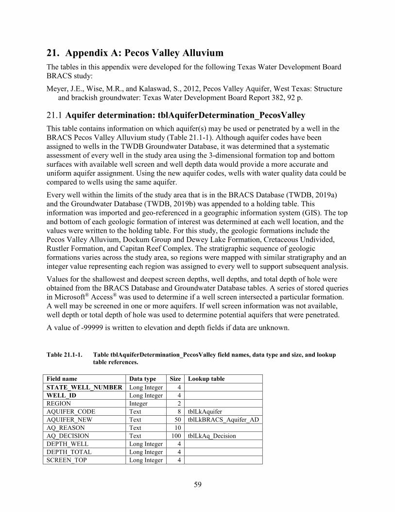
59
21. Appendix A: Pecos Valley Alluvium The tables in this appendix were developed for the following Texas Water Development Board BRACS study: Meyer, J.E., Wise, M.R., and Kalaswad, S., 2012, Pecos Valley Aquifer, West Texas: Structure
and brackish groundwater: Texas Water Development Board Report 382, 92 p.
21.1 Aquifer determination: tblAquiferDetermination_PecosValley This table contains information on which aquifer(s) may be used or penetrated by a well in the BRACS Pecos Valley Alluvium study (Table 21.1-1). Although aquifer codes have been assigned to wells in the TWDB Groundwater Database, it was determined that a systematic assessment of every well in the study area using the 3-dimensional formation top and bottom surfaces with available well screen and well depth data would provide a more accurate and uniform aquifer assignment. Using the new aquifer codes, wells with water quality data could be compared to wells using the same aquifer. Every well within the limits of the study area that is in the BRACS Database (TWDB, 2019a) and the Groundwater Database (TWDB, 2019b) was appended to a holding table. This information was imported and geo-referenced in a geographic information system (GIS). The top and bottom of each geologic formation of interest was determined at each well location, and the values were written to the holding table. For this study, the geologic formations include the Pecos Valley Alluvium, Dockum Group and Dewey Lake Formation, Cretaceous Undivided, Rustler Formation, and Capitan Reef Complex. The stratigraphic sequence of geologic formations varies across the study area, so regions were mapped with similar stratigraphy and an integer value representing each region was assigned to every well to support subsequent analysis. Values for the shallowest and deepest screen depths, well depths, and total depth of hole were obtained from the BRACS Database and Groundwater Database tables. A series of stored queries in Microsoft® Access® was used to determine if a well screen intersected a particular formation. A well may be screened in one or more aquifers. If well screen information was not available, well depth or total depth of hole was used to determine potential aquifers that were penetrated. A value of -99999 is written to elevation and depth fields if data are unknown.
Table 21.1-1. Table tblAquiferDetermination_PecosValley field names, data type and size, and lookup table references.
Field name Data type Size Lookup table STATE_WELL_NUMBER Long Integer 4
WELL_ID Long Integer 4
REGION Integer 2
AQUIFER_CODE Text 8 tblLkAquifer AQUIFER_NEW Text 50 tblLkBRACS_Aquifer_AD AQ_REASON Text 10
AQ_DECISION Text 100 tblLkAq_Decision DEPTH_WELL Long Integer 4
DEPTH_TOTAL Long Integer 4
SCREEN_TOP Long Integer 4
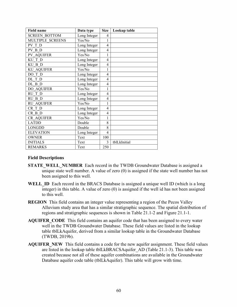
60
Field name Data type Size Lookup table SCREEN_BOTTOM Long Integer 4
MULTIPLE_SCREENS Yes/No 1
PV_T_D Long Integer 4
PV_B_D Long Integer 4
PV_AQUIFER Yes/No 1
KU_T_D Long Integer 4
KU_B_D Long Integer 4
KU_AQUIFER Yes/No 1
DO_T_D Long Integer 4
DL_T_D Long Integer 4
DL_B_D Long Integer 4
DO_AQUIFER Yes/No 1
RU_T_D Long Integer 4
RU_B_D Long Integer 4
RU_AQUIFER Yes/No 1
CR_T_D Long Integer 4
CR_B_D Long Integer 4
CR_AQUIFER Yes/No 1
LATDD Double 8
LONGDD Double 8
ELEVATION Long Integer 4
OWNER Text 100
INITIALS Text 3 tblLkInitial REMARKS Text 250
Field Descriptions STATE_WELL_NUMBER Each record in the TWDB Groundwater Database is assigned a
unique state well number. A value of zero (0) is assigned if the state well number has not been assigned to this well.
WELL_ID Each record in the BRACS Database is assigned a unique well ID (which is a long integer) in this table. A value of zero (0) is assigned if the well id has not been assigned to this well.
REGION This field contains an integer value representing a region of the Pecos Valley Alluvium study area that has a similar stratigraphic sequence. The spatial distribution of regions and stratigraphic sequences is shown in Table 21.1-2 and Figure 21.1-1.
AQUIFER_CODE This field contains an aquifer code that has been assigned to every water well in the TWDB Groundwater Database. These field values are listed in the lookup table tblLkAquifer, derived from a similar lookup table in the Groundwater Database (TWDB, 2019b).
AQUIFER_NEW This field contains a code for the new aquifer assignment. These field values are listed in the lookup table tblLkBRACSAquifer_AD (Table 21.1-3). This table was created because not all of these aquifer combinations are available in the Groundwater Database aquifer code table (tblLkAquifer). This table will grow with time.
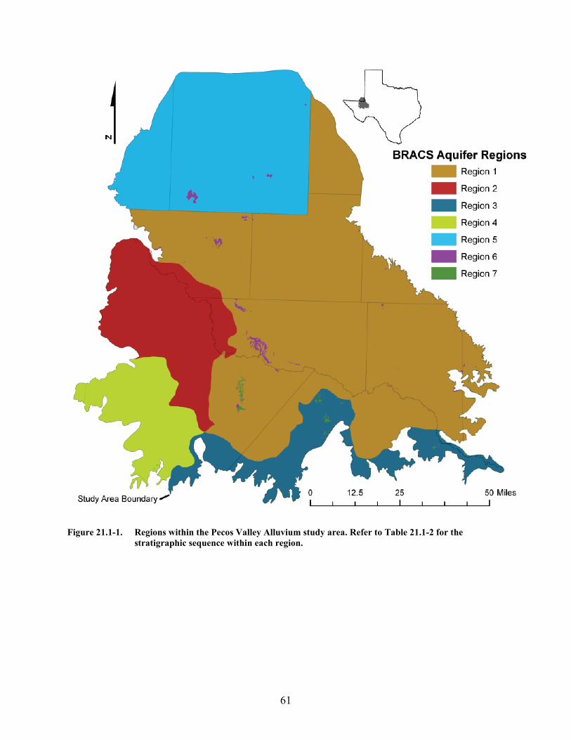
61
Figure 21.1-1. Regions within the Pecos Valley Alluvium study area. Refer to Table 21.1-2 for the
stratigraphic sequence within each region.
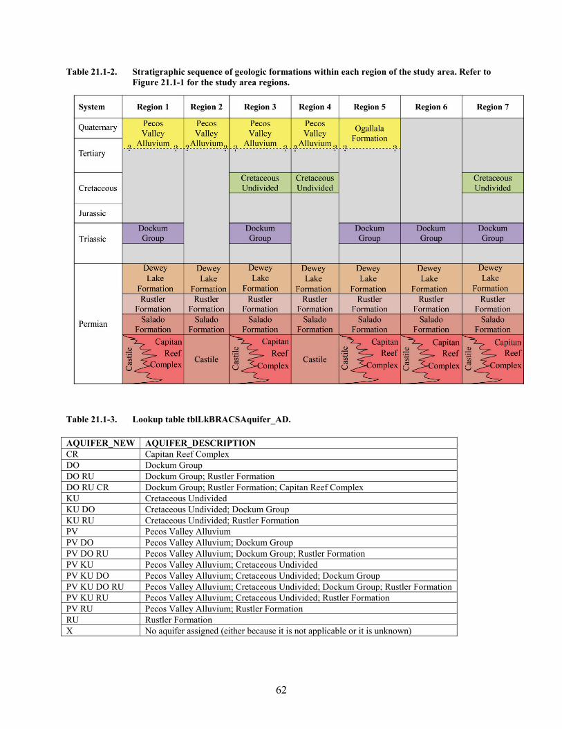
62
Table 21.1-2. Stratigraphic sequence of geologic formations within each region of the study area. Refer to Figure 21.1-1 for the study area regions.
Table 21.1-3. Lookup table tblLkBRACSAquifer_AD. AQUIFER_NEW AQUIFER_DESCRIPTION CR Capitan Reef Complex DO Dockum Group DO RU Dockum Group; Rustler Formation DO RU CR Dockum Group; Rustler Formation; Capitan Reef Complex KU Cretaceous Undivided KU DO Cretaceous Undivided; Dockum Group KU RU Cretaceous Undivided; Rustler Formation PV Pecos Valley Alluvium PV DO Pecos Valley Alluvium; Dockum Group PV DO RU Pecos Valley Alluvium; Dockum Group; Rustler Formation PV KU Pecos Valley Alluvium; Cretaceous Undivided PV KU DO Pecos Valley Alluvium; Cretaceous Undivided; Dockum Group PV KU DO RU Pecos Valley Alluvium; Cretaceous Undivided; Dockum Group; Rustler Formation PV KU RU Pecos Valley Alluvium; Cretaceous Undivided; Rustler Formation PV RU Pecos Valley Alluvium; Rustler Formation RU Rustler Formation X No aquifer assigned (either because it is not applicable or it is unknown)
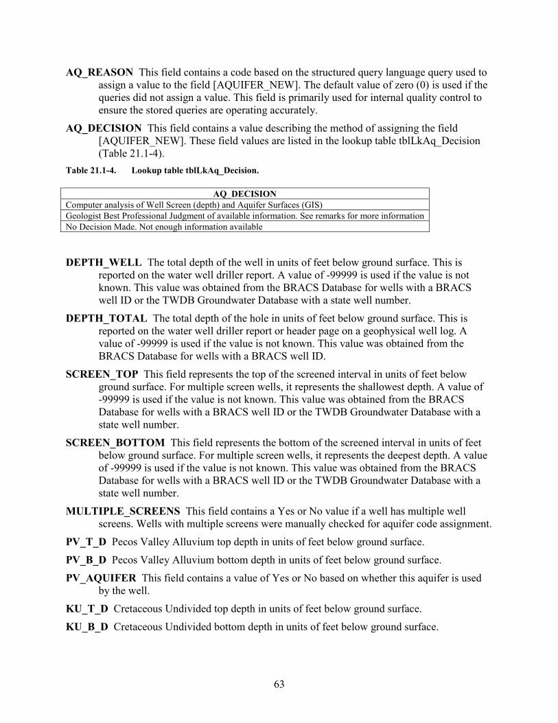
63
AQ_REASON This field contains a code based on the structured query language query used to assign a value to the field [AQUIFER_NEW]. The default value of zero (0) is used if the queries did not assign a value. This field is primarily used for internal quality control to ensure the stored queries are operating accurately.
AQ_DECISION This field contains a value describing the method of assigning the field [AQUIFER_NEW]. These field values are listed in the lookup table tblLkAq_Decision (Table 21.1-4).
Table 21.1-4. Lookup table tblLkAq_Decision.
AQ_DECISION Computer analysis of Well Screen (depth) and Aquifer Surfaces (GIS) Geologist Best Professional Judgment of available information. See remarks for more information No Decision Made. Not enough information available
DEPTH_WELL The total depth of the well in units of feet below ground surface. This is
reported on the water well driller report. A value of -99999 is used if the value is not known. This value was obtained from the BRACS Database for wells with a BRACS well ID or the TWDB Groundwater Database with a state well number.
DEPTH_TOTAL The total depth of the hole in units of feet below ground surface. This is reported on the water well driller report or header page on a geophysical well log. A value of -99999 is used if the value is not known. This value was obtained from the BRACS Database for wells with a BRACS well ID.
SCREEN_TOP This field represents the top of the screened interval in units of feet below ground surface. For multiple screen wells, it represents the shallowest depth. A value of -99999 is used if the value is not known. This value was obtained from the BRACS Database for wells with a BRACS well ID or the TWDB Groundwater Database with a state well number.
SCREEN_BOTTOM This field represents the bottom of the screened interval in units of feet below ground surface. For multiple screen wells, it represents the deepest depth. A value of -99999 is used if the value is not known. This value was obtained from the BRACS Database for wells with a BRACS well ID or the TWDB Groundwater Database with a state well number.
MULTIPLE_SCREENS This field contains a Yes or No value if a well has multiple well screens. Wells with multiple screens were manually checked for aquifer code assignment.
PV_T_D Pecos Valley Alluvium top depth in units of feet below ground surface. PV_B_D Pecos Valley Alluvium bottom depth in units of feet below ground surface. PV_AQUIFER This field contains a value of Yes or No based on whether this aquifer is used
by the well. KU_T_D Cretaceous Undivided top depth in units of feet below ground surface. KU_B_D Cretaceous Undivided bottom depth in units of feet below ground surface.
64
KU_AQUIFER This field contains a value of Yes or No based on whether this aquifer is used by the well.
DO_T_D Dockum Group top depth in units of feet below ground surface. DL_T_D Dewey Lake Formation top depth in units of feet below ground surface. DL_B_D Dewey Lake Formation top depth in units of feet below ground surface. DO_AQUIFER This field contains a value of Yes or No based on whether this aquifer is used
by the well. RU_T_D Rustler Formation top depth in units of feet below ground surface. RU_B_D Rustler Formation bottom depth in units of feet below ground surface. RU_AQUIFER This field contains a value of Yes or No based on whether this aquifer is used
by the well. CR_T_D Capitan Reef Complex top depth in units of feet below ground surface. CR_B_D Capitan Reef Complex bottom depth in units of feet below ground surface. CR_AQUIFER This field contains a value of Yes or No based on whether this aquifer is used
by the well. LATDD Latitude of the well site in units of decimal degrees. Latitude is a positive value,
referring to a site north of the earth’s equator. Latitude and longitude coordinates are obtained from multiple sources. Latitude is obtained based on a North American Datum of 1983. This value was obtained from the well location table.
LONGDD Longitude of the well site in units of decimal degrees. Longitude is a negative value, referring to a site west of the Prime Meridian in Greenwich, United Kingdom. Latitude and longitude coordinates are obtained from multiple sources. Longitude is based on a North American Datum of 1983. This value was obtained from the well location table.
ELEVATION The elevation of the well site in units of feet above mean sea level. The elevation is determined using spatial analysis in a geographic information system by comparing the well site with the 30-meter digital elevation model for Texas. This value was obtained from the well location table. A value of -99999 is used if the value is not known.
OWNER The name of the well owner. This value was obtained from the well location table. INITIALS Initials of person who last edited the record. REMARKS General remarks associated with the well record.
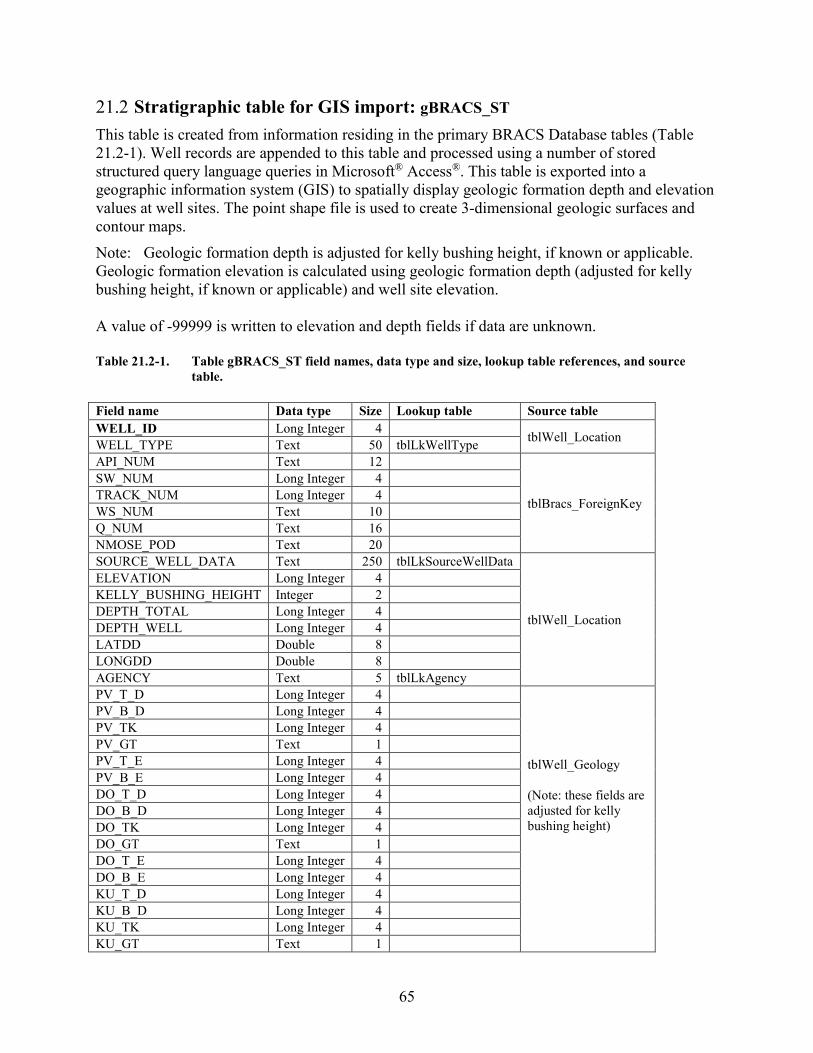
65
21.2 Stratigraphic table for GIS import: gBRACS_ST This table is created from information residing in the primary BRACS Database tables (Table 21.2-1). Well records are appended to this table and processed using a number of stored structured query language queries in Microsoft® Access®. This table is exported into a geographic information system (GIS) to spatially display geologic formation depth and elevation values at well sites. The point shape file is used to create 3-dimensional geologic surfaces and contour maps. Note: Geologic formation depth is adjusted for kelly bushing height, if known or applicable. Geologic formation elevation is calculated using geologic formation depth (adjusted for kelly bushing height, if known or applicable) and well site elevation. A value of -99999 is written to elevation and depth fields if data are unknown. Table 21.2-1. Table gBRACS_ST field names, data type and size, lookup table references, and source
table. Field name Data type Size Lookup table Source table WELL_ID Long Integer 4
tblWell_Location WELL_TYPE Text 50 tblLkWellType
API_NUM Text 12
tblBracs_ForeignKey
SW_NUM Long Integer 4
TRACK_NUM Long Integer 4
WS_NUM Text 10
Q_NUM Text 16
NMOSE_POD Text 20
SOURCE_WELL_DATA Text 250 tblLkSourceWellData
tblWell_Location
ELEVATION Long Integer 4
KELLY_BUSHING_HEIGHT Integer 2
DEPTH_TOTAL Long Integer 4
DEPTH_WELL Long Integer 4
LATDD Double 8
LONGDD Double 8
AGENCY Text 5 tblLkAgency PV_T_D Long Integer 4
tblWell_Geology (Note: these fields are adjusted for kelly bushing height)
PV_B_D Long Integer 4
PV_TK Long Integer 4
PV_GT Text 1
PV_T_E Long Integer 4
PV_B_E Long Integer 4
DO_T_D Long Integer 4
DO_B_D Long Integer 4
DO_TK Long Integer 4
DO_GT Text 1
DO_T_E Long Integer 4
DO_B_E Long Integer 4
KU_T_D Long Integer 4
KU_B_D Long Integer 4
KU_TK Long Integer 4
KU_GT Text 1
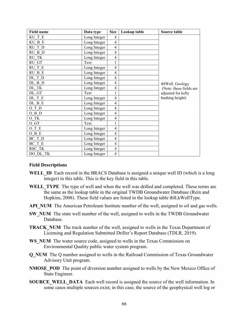
66
Field name Data type Size Lookup table Source table KU_T_E Long Integer 4
tblWell_Geology (Note: these fields are adjusted for kelly bushing height)
KU_B_E Long Integer 4
RU_T_D Long Integer 4
RU_B_D Long Integer 4
RU_TK Long Integer 4
RU_GT Text 1
RU_T_E Long Integer 4
RU_B_E Long Integer 4
DL_T_D Long Integer 4
DL_B_D Long Integer 4
DL_TK Long Integer 4
DL_GT Text 1
DL_T_E Long Integer 4
DL_B_E Long Integer 4
O_T_D Long Integer 4
O_B_D Long Integer 4
O_TK Long Integer 4
O_GT Text 1
O_T_E Long Integer 4
O_B_E Long Integer 4
BC_T_D Long Integer 4
BC_T_E Long Integer 4
RSC_TK Long Integer 4
DO_DL_TK Long Integer 4
Field Descriptions WELL_ID Each record in the BRACS Database is assigned a unique well ID (which is a long
integer) in this table. This is the key field in this table. WELL_TYPE The type of well and when the well was drilled and completed. These terms are
the same as the lookup table in the original TWDB Groundwater Database (Rein and Hopkins, 2008). These field values are listed in the lookup table tblLkWellType.
API_NUM The American Petroleum Institute number of the well, assigned to oil and gas wells. SW_NUM The state well number of the well, assigned to wells in the TWDB Groundwater
Database. TRACK_NUM The track number of the well, assigned to wells in the Texas Department of
Licensing and Regulation Submitted Driller’s Report Database (TDLR, 2019). WS_NUM The water source code, assigned to wells in the Texas Commission on
Environmental Quality public water system program. Q_NUM The Q number assigned to wells in the Railroad Commission of Texas Groundwater
Advisory Unit program. NMOSE_POD The point of diversion number assigned to wells by the New Mexico Office of
State Engineer. SOURCE_WELL_DATA Each well record is assigned the source of the well information. In
some cases multiple sources exist; in this case, the source of the geophysical well log or
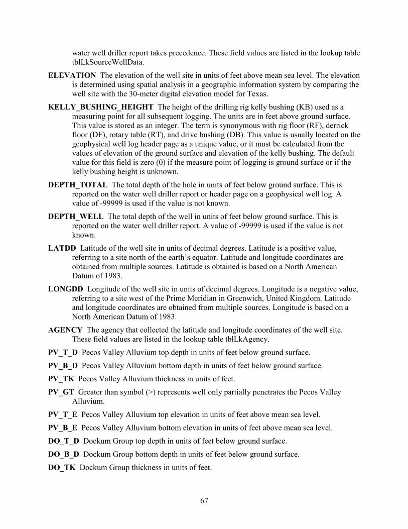
67
water well driller report takes precedence. These field values are listed in the lookup table tblLkSourceWellData.
ELEVATION The elevation of the well site in units of feet above mean sea level. The elevation is determined using spatial analysis in a geographic information system by comparing the well site with the 30-meter digital elevation model for Texas.
KELLY_BUSHING_HEIGHT The height of the drilling rig kelly bushing (KB) used as a measuring point for all subsequent logging. The units are in feet above ground surface. This value is stored as an integer. The term is synonymous with rig floor (RF), derrick floor (DF), rotary table (RT), and drive bushing (DB). This value is usually located on the geophysical well log header page as a unique value, or it must be calculated from the values of elevation of the ground surface and elevation of the kelly bushing. The default value for this field is zero (0) if the measure point of logging is ground surface or if the kelly bushing height is unknown.
DEPTH_TOTAL The total depth of the hole in units of feet below ground surface. This is reported on the water well driller report or header page on a geophysical well log. A value of -99999 is used if the value is not known.
DEPTH_WELL The total depth of the well in units of feet below ground surface. This is reported on the water well driller report. A value of -99999 is used if the value is not known.
LATDD Latitude of the well site in units of decimal degrees. Latitude is a positive value, referring to a site north of the earth’s equator. Latitude and longitude coordinates are obtained from multiple sources. Latitude is obtained is based on a North American Datum of 1983.
LONGDD Longitude of the well site in units of decimal degrees. Longitude is a negative value, referring to a site west of the Prime Meridian in Greenwich, United Kingdom. Latitude and longitude coordinates are obtained from multiple sources. Longitude is based on a North American Datum of 1983.
AGENCY The agency that collected the latitude and longitude coordinates of the well site. These field values are listed in the lookup table tblLkAgency.
PV_T_D Pecos Valley Alluvium top depth in units of feet below ground surface. PV_B_D Pecos Valley Alluvium bottom depth in units of feet below ground surface. PV_TK Pecos Valley Alluvium thickness in units of feet. PV_GT Greater than symbol (>) represents well only partially penetrates the Pecos Valley
Alluvium. PV_T_E Pecos Valley Alluvium top elevation in units of feet above mean sea level. PV_B_E Pecos Valley Alluvium bottom elevation in units of feet above mean sea level. DO_T_D Dockum Group top depth in units of feet below ground surface. DO_B_D Dockum Group bottom depth in units of feet below ground surface. DO_TK Dockum Group thickness in units of feet.
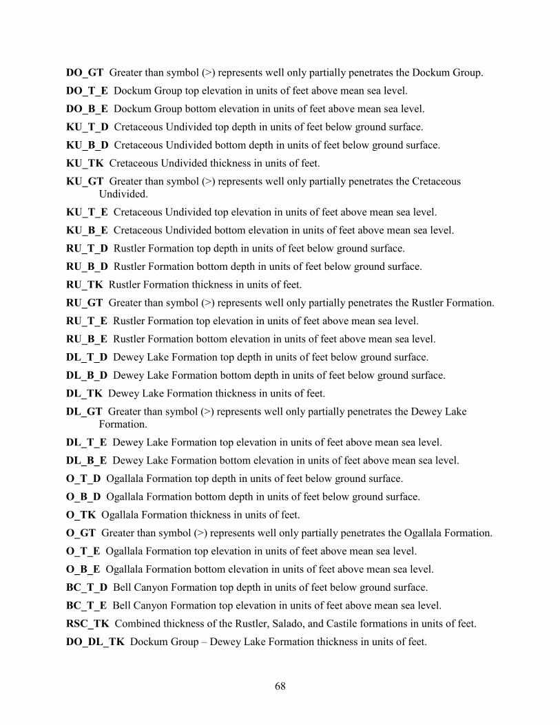
68
DO_GT Greater than symbol (>) represents well only partially penetrates the Dockum Group. DO_T_E Dockum Group top elevation in units of feet above mean sea level. DO_B_E Dockum Group bottom elevation in units of feet above mean sea level. KU_T_D Cretaceous Undivided top depth in units of feet below ground surface. KU_B_D Cretaceous Undivided bottom depth in units of feet below ground surface. KU_TK Cretaceous Undivided thickness in units of feet. KU_GT Greater than symbol (>) represents well only partially penetrates the Cretaceous
Undivided. KU_T_E Cretaceous Undivided top elevation in units of feet above mean sea level. KU_B_E Cretaceous Undivided bottom elevation in units of feet above mean sea level. RU_T_D Rustler Formation top depth in units of feet below ground surface. RU_B_D Rustler Formation bottom depth in units of feet below ground surface. RU_TK Rustler Formation thickness in units of feet. RU_GT Greater than symbol (>) represents well only partially penetrates the Rustler Formation. RU_T_E Rustler Formation top elevation in units of feet above mean sea level. RU_B_E Rustler Formation bottom elevation in units of feet above mean sea level. DL_T_D Dewey Lake Formation top depth in units of feet below ground surface. DL_B_D Dewey Lake Formation bottom depth in units of feet below ground surface. DL_TK Dewey Lake Formation thickness in units of feet. DL_GT Greater than symbol (>) represents well only partially penetrates the Dewey Lake
Formation. DL_T_E Dewey Lake Formation top elevation in units of feet above mean sea level. DL_B_E Dewey Lake Formation bottom elevation in units of feet above mean sea level. O_T_D Ogallala Formation top depth in units of feet below ground surface. O_B_D Ogallala Formation bottom depth in units of feet below ground surface. O_TK Ogallala Formation thickness in units of feet. O_GT Greater than symbol (>) represents well only partially penetrates the Ogallala Formation. O_T_E Ogallala Formation top elevation in units of feet above mean sea level. O_B_E Ogallala Formation bottom elevation in units of feet above mean sea level. BC_T_D Bell Canyon Formation top depth in units of feet below ground surface. BC_T_E Bell Canyon Formation top elevation in units of feet above mean sea level. RSC_TK Combined thickness of the Rustler, Salado, and Castile formations in units of feet. DO_DL_TK Dockum Group – Dewey Lake Formation thickness in units of feet.
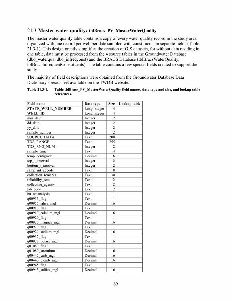
69
21.3 Master water quality: tblBracs_PV_MasterWaterQuality The master water quality table contains a copy of every water quality record in the study area organized with one record per well per date sampled with constituents in separate fields (Table 21.3-1). This design greatly simplifies the creation of GIS datasets, for without data residing in one table, data must be processed from the 4 source tables in the Groundwater Database (dbo_waterqua; dbo_infreqconst) and the BRACS Database (tblBracsWaterQuality; tblBracsInfrequentConstituents). The table contains a few special fields created to support the study. The majority of field descriptions were obtained from the Groundwater Database Data Dictionary spreadsheet available on the TWDB website. Table 21.3-1. Table tblBracs_PV_MasterWaterQuality field names, data type and size, and lookup table
references. Field name Data type Size Lookup table STATE_WELL_NUMBER Long Integer 4
WELL_ID Long Integer 4
mm_date Integer 2
dd_date Integer 2
yy_date Integer 2
sample_number Integer 2
SOURCE_DATA Text 200
TDS_RANGE Text 255
TDS_RNG_NUM Integer 2
sample_time Text 4
temp_centigrade Decimal 16
top_s_interval Integer 2
bottom_s_interval Integer 2
samp_int_aqcode Text 8
collection_remarks Text 30
reliability_rem Text 2
collecting_agency Text 2
lab_code Text 2
bu_wqanalysis Text 1
q00955_flag Text 1
q00955_silica_mgl Decimal 16
q00910_flag Text 1
q00910_calcium_mgl Decimal 16
q00920_flag Text 1
q00920_magnes_mgl Decimal 16
q00929_flag Text 1
q00929_sodium_mgl Decimal 16
q00937_flag Text 1
q00937_potass_mgl Decimal 16
q01080_flag Text 1
q01080_strontium Decimal 16
q00445_carb_mgl Decimal 16
q00440_bicarb_mgl Decimal 16
q00945_flag Text 1
q00945_sulfate_mgl Decimal 16
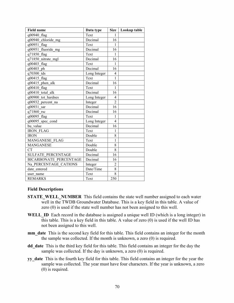
70
Field name Data type Size Lookup table q00940_flag Text 1
q00940_chloride_mg Decimal 16
q00951_flag Text 1
q00951_fluoride_mg Decimal 16
q71850_flag Text 1
q71850_nitrate_mgl Decimal 16
q00403_flag Text 1
q00403_ph Decimal 16
q70300_tds Long Integer 4
q00415_flag Text 1
q00415_phen_alk Decimal 16
q00410_flag Text 1
q00410_total_alk Decimal 16
q00900_tot_hardnes Long Integer 4
q00932_percent_na Integer 2
q00931_sar Decimal 16
q71860_rsc Decimal 16
q00095_flag Text 1
q00095_spec_cond Long Integer 4
bu_value Decimal 16
IRON_FLAG Text 1
IRON Double 8
MANGANESE_FLAG Text 1
MANGANESE Double 8
CT Double 8
SULFATE_PERCENTAGE Decimal 16
BICARBONATE_PERCENTAGE Decimal 16
Na_PERCENTAGE_CATIONS Integer 2
date_entered Date/Time 8
user_name Text 8
REMARKS Text 250
Field Descriptions STATE_WELL_NUMBER This field contains the state well number assigned to each water
well in the TWDB Groundwater Database. This is a key field in this table. A value of zero (0) is used if the state well number has not been assigned to this well.
WELL_ID Each record in the database is assigned a unique well ID (which is a long integer) in this table. This is a key field in this table. A value of zero (0) is used if the well ID has not been assigned to this well.
mm_date This is the second key field for this table. This field contains an integer for the month the sample was collected. If the month is unknown, a zero (0) is required.
dd_date This is the third key field for this table. This field contains an integer for the day the sample was collected. If the day is unknown, a zero (0) is required.
yy_date This is the fourth key field for this table. This field contains an integer for the year the sample was collected. The year must have four characters. If the year is unknown, a zero (0) is required.
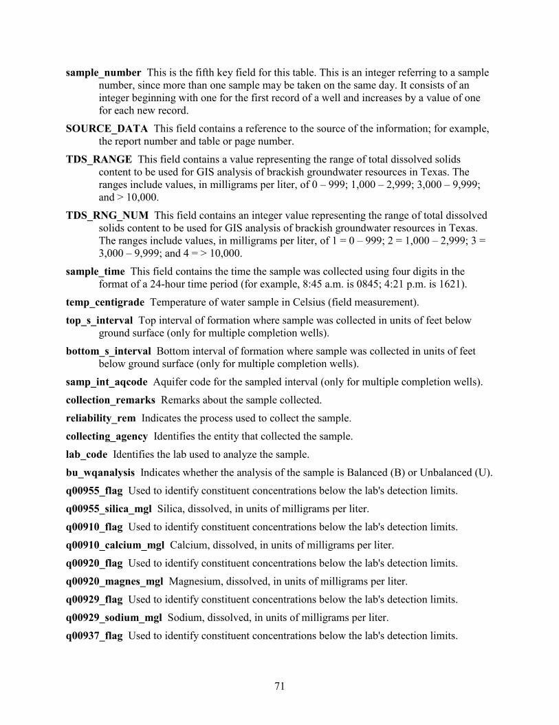
71
sample_number This is the fifth key field for this table. This is an integer referring to a sample number, since more than one sample may be taken on the same day. It consists of an integer beginning with one for the first record of a well and increases by a value of one for each new record.
SOURCE_DATA This field contains a reference to the source of the information; for example, the report number and table or page number.
TDS_RANGE This field contains a value representing the range of total dissolved solids content to be used for GIS analysis of brackish groundwater resources in Texas. The ranges include values, in milligrams per liter, of 0 – 999; 1,000 – 2,999; 3,000 – 9,999; and > 10,000.
TDS_RNG_NUM This field contains an integer value representing the range of total dissolved solids content to be used for GIS analysis of brackish groundwater resources in Texas. The ranges include values, in milligrams per liter, of 1 = 0 – 999; 2 = 1,000 – 2,999; 3 = 3,000 – 9,999; and 4 = > 10,000.
sample_time This field contains the time the sample was collected using four digits in the format of a 24-hour time period (for example, 8:45 a.m. is 0845; 4:21 p.m. is 1621).
temp_centigrade Temperature of water sample in Celsius (field measurement). top_s_interval Top interval of formation where sample was collected in units of feet below
ground surface (only for multiple completion wells). bottom_s_interval Bottom interval of formation where sample was collected in units of feet
below ground surface (only for multiple completion wells). samp_int_aqcode Aquifer code for the sampled interval (only for multiple completion wells). collection_remarks Remarks about the sample collected. reliability_rem Indicates the process used to collect the sample. collecting_agency Identifies the entity that collected the sample. lab_code Identifies the lab used to analyze the sample. bu_wqanalysis Indicates whether the analysis of the sample is Balanced (B) or Unbalanced (U). q00955_flag Used to identify constituent concentrations below the lab's detection limits. q00955_silica_mgl Silica, dissolved, in units of milligrams per liter. q00910_flag Used to identify constituent concentrations below the lab's detection limits. q00910_calcium_mgl Calcium, dissolved, in units of milligrams per liter. q00920_flag Used to identify constituent concentrations below the lab's detection limits. q00920_magnes_mgl Magnesium, dissolved, in units of milligrams per liter. q00929_flag Used to identify constituent concentrations below the lab's detection limits. q00929_sodium_mgl Sodium, dissolved, in units of milligrams per liter. q00937_flag Used to identify constituent concentrations below the lab's detection limits.
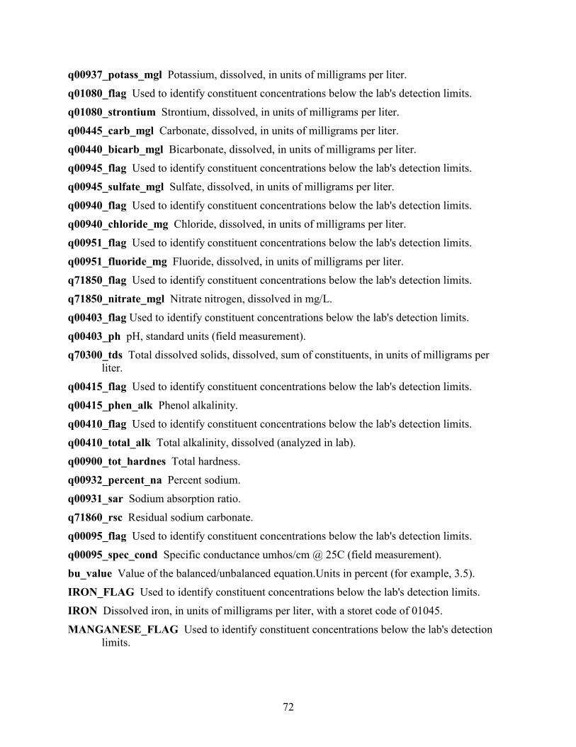
72
q00937_potass_mgl Potassium, dissolved, in units of milligrams per liter. q01080_flag Used to identify constituent concentrations below the lab's detection limits. q01080_strontium Strontium, dissolved, in units of milligrams per liter. q00445_carb_mgl Carbonate, dissolved, in units of milligrams per liter. q00440_bicarb_mgl Bicarbonate, dissolved, in units of milligrams per liter. q00945_flag Used to identify constituent concentrations below the lab's detection limits. q00945_sulfate_mgl Sulfate, dissolved, in units of milligrams per liter. q00940_flag Used to identify constituent concentrations below the lab's detection limits. q00940_chloride_mg Chloride, dissolved, in units of milligrams per liter. q00951_flag Used to identify constituent concentrations below the lab's detection limits. q00951_fluoride_mg Fluoride, dissolved, in units of milligrams per liter. q71850_flag Used to identify constituent concentrations below the lab's detection limits. q71850_nitrate_mgl Nitrate nitrogen, dissolved in mg/L. q00403_flag Used to identify constituent concentrations below the lab's detection limits. q00403_ph pH, standard units (field measurement). q70300_tds Total dissolved solids, dissolved, sum of constituents, in units of milligrams per
liter. q00415_flag Used to identify constituent concentrations below the lab's detection limits. q00415_phen_alk Phenol alkalinity. q00410_flag Used to identify constituent concentrations below the lab's detection limits. q00410_total_alk Total alkalinity, dissolved (analyzed in lab). q00900_tot_hardnes Total hardness. q00932_percent_na Percent sodium. q00931_sar Sodium absorption ratio. q71860_rsc Residual sodium carbonate. q00095_flag Used to identify constituent concentrations below the lab's detection limits. q00095_spec_cond Specific conductance umhos/cm @ 25C (field measurement). bu_value Value of the balanced/unbalanced equation.Units in percent (for example, 3.5). IRON_FLAG Used to identify constituent concentrations below the lab's detection limits. IRON Dissolved iron, in units of milligrams per liter, with a storet code of 01045. MANGANESE_FLAG Used to identify constituent concentrations below the lab's detection
limits.
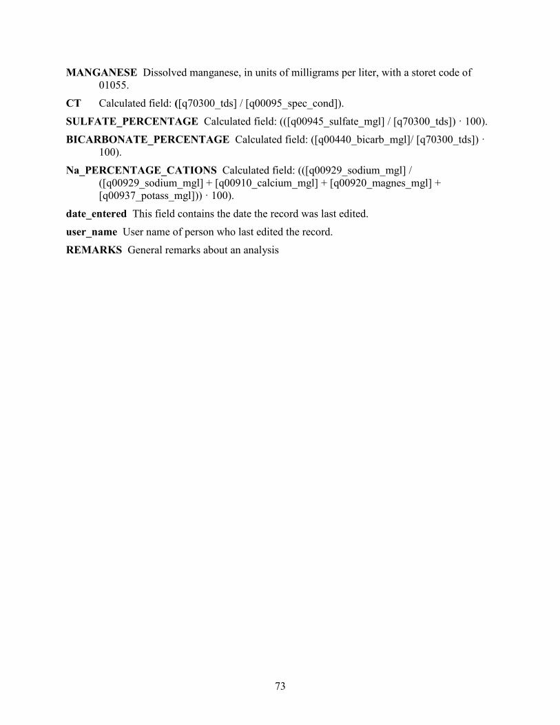
73
MANGANESE Dissolved manganese, in units of milligrams per liter, with a storet code of 01055.
CT Calculated field: ([q70300_tds] / [q00095_spec_cond]). SULFATE_PERCENTAGE Calculated field: (([q00945_sulfate_mgl] / [q70300_tds]) · 100). BICARBONATE_PERCENTAGE Calculated field: ([q00440_bicarb_mgl]/ [q70300_tds]) ·
100). Na_PERCENTAGE_CATIONS Calculated field: (([q00929_sodium_mgl] /
([q00929_sodium_mgl] + [q00910_calcium_mgl] + [q00920_magnes_mgl] + [q00937_potass_mgl])) · 100).
date_entered This field contains the date the record was last edited. user_name User name of person who last edited the record. REMARKS General remarks about an analysis
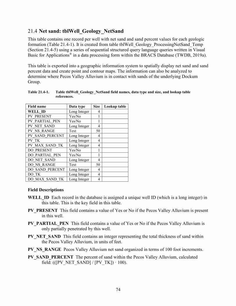
74
21.4 Net sand: tblWell_Geology_NetSand This table contains one record per well with net sand and sand percent values for each geologic formation (Table 21.4-1). It is created from table tblWell_Geology_ProcessingNetSand_Temp (Section 21.4-5) using a series of sequential structured query language queries written in Visual Basic for Applications® in a data processing form within the BRACS Database (TWDB, 2019a). This table is exported into a geographic information system to spatially display net sand and sand percent data and create point and contour maps. The information can also be analyzed to determine where Pecos Valley Alluvium is in contact with sands of the underlying Dockum Group. Table 21.4-1. Table tblWell_Geology_NetSand field names, data type and size, and lookup table
references. Field name Data type Size Lookup table WELL_ID Long Integer 4
PV_PRESENT Yes/No 1
PV_PARTIAL_PEN Yes/No 1
PV_NET_SAND Long Integer 4
PV_NS_RANGE Text 50
PV_SAND_PERCENT Long Integer 4
PV_TK Long Integer 4
PV_MAX_SAND_TK Long Integer 4
DO_PRESENT Yes/No 1
DO_PARTIAL_PEN Yes/No 1
DO_NET_SAND Long Integer 4
DO_NS_RANGE Text 50
DO_SAND_PERCENT Long Integer 4
DO_TK Long Integer 4
DO_MAX_SAND_TK Long Integer 4
Field Descriptions WELL_ID Each record in the database is assigned a unique well ID (which is a long integer) in
this table. This is the key field in this table. PV_PRESENT This field contains a value of Yes or No if the Pecos Valley Alluvium is present
in this well. PV_PARTIAL_PEN This field contains a value of Yes or No if the Pecos Valley Alluvium is
only partially penetrated by this well. PV_NET_SAND This field contains an integer representing the total thickness of sand within
the Pecos Valley Alluvium, in units of feet. PV_NS_RANGE Pecos Valley Alluvium net sand organized in terms of 100 foot increments. PV_SAND_PERCENT The percent of sand within the Pecos Valley Alluvium, calculated
field: (([PV_NET_SAND] / [PV_TK]) · 100).

75
PV_TK Pecos Valley Alluvium thickness, calculated from table tblWell_Geology_ProcessingNetSand_Temp fields: ([PV_B_D] – [PV_T_D]). The units are feet.
PV_MAX_SAND_TK This field contains the thickest sand within the Pecos Valley Alluvium, in units of feet.
DO_PRESENT This field contains a value of Yes or No if the Dockum Group is present in this well.
DO_PARTIAL_PEN This field contains a value of Yes or No if the Dockum Group is only partially penetrated by this well. Note that in the BRACS Pecos Valley Alluvium study the Dockum Group was combined with the Dewey Lake Formation as one mapped unit.
DO_NET_SAND This field contains an integer representing the total thickness of sand within the Dockum Group, in units of feet. Note that in the BRACS Pecos Valley Alluvium study the Dockum Group was combined with the Dewey Lake Formation as one mapped unit.
DO_NS_RANGE Dockum Group net sand organized in terms of 100 foot increments. DO_SAND_PERCENT The percent of sand within the Dockum Group, calculated field:
(([DO_NET_SAND] / [DO_TK]) · 100). Note that in the BRACS Pecos Valley Alluvium study the Dockum Group was combined with the Dewey Lake Formation as one mapped unit. The sand percent values will be lower than if the Dockum Group were mapped as one unit.
DO_TK Dockum Group thickness, calculated from table tblWell_Geology_ProcessingNetSand_Temp fields: ([DL_B_D] – [DO_T_D]). The units are feet. Note that in the BRACS Pecos Valley Alluvium study the Dockum Group was combined with the Dewey Lake Formation as one mapped unit. The thickness values will be larger than if the Dockum Group were mapped as one unit.
DO_MAX_SAND_TK This field contains the thickest sand within the Dockum Group, in units of feet.
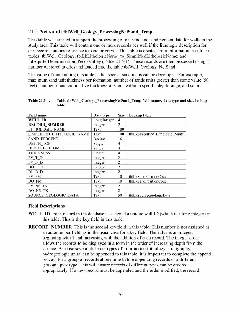
76
21.5 Net sand: tblWell_Geology_ProcessingNetSand_Temp This table was created to support the processing of net sand and sand percent data for wells in the study area. This table will contain one or more records per well if the lithologic description for any record contains reference to sand or gravel. This table is created from information residing in tables: tblWell_Geology; tblLkLithologicName_to_SimplifiedLithologicName; and tblAquiferDetermination_PecosValley (Table 21.5-1). These records are then processed using a number of stored queries and loaded into the table tblWell_Geology_NetSand. The value of maintaining this table is that special sand maps can be developed. For example, maximum sand unit thickness per formation, number of sands units greater than some value (50 feet), number of and cumulative thickness of sands within a specific depth range, and so on. Table 21.5-1. Table tblWell_Geology_ProcessingNetSand_Temp field names, data type and size, lookup
table. Field name Data type Size Lookup table WELL_ID Long Integer 4 RECORD_NUMBER Integer 2 LITHOLOGIC_NAME Text 100 SIMPLIFIED_LITHOLOGIC_NAME Text 100 tblLkSimplified_Lithologic_Name SAND_PERCENT Decimal 16 DEPTH_TOP Single 4 DEPTH_BOTTOM Single 4 THICKNESS Single 4 PV_T_D Integer 2 PV_B_D Integer 2 DO_T_D Integer 2 DL_B_D Integer 2 PV_FM Text 10 tblLkSandPositionCode DO_FM Text 10 tblLkSandPositionCode PV_NS_TK Integer 2 DO_NS_TK Integer 2 SOURCE_GEOLOGIC_DATA Text 50 tblLkSourceGeologicData Field Descriptions WELL_ID Each record in the database is assigned a unique well ID (which is a long integer) in
this table. This is the key field in this table. RECORD_NUMBER This is the second key field in this table. This number is not assigned as
an autonumber field, as in the usual case for a key field. The value is an integer, beginning with 1 and increasing with the addition of each record. The integer order allows the records to be displayed in a form in the order of increasing depth from the surface. Because several different types of information (lithology, stratigraphy, hydrogeologic units) can be appended to this table, it is important to complete the append process for a group of records at one time before appending records of a different geologic pick type. This will ensure records of different types can be ordered appropriately. If a new record must be appended and the order modified, the record
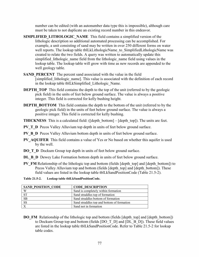
77
number can be edited (with an autonumber data type this is impossible), although care must be taken to not duplicate an existing record number in this endeavor.
SIMPLIFIED_LITHOLOGIC_NAME This field contains a simplified version of the lithologic description so additional automated processing can be accomplished. For example, a unit consisting of sand may be written in over 250 different forms on water well reports. The lookup table tblLkLithologicName_to_SimplifiedLithologicName was created to relate the two fields. A query was written to automatically update this simplified_lithologic_name field from the lithologic_name field using values in the lookup table. The lookup table will grow with time as new records are appended to the well geology table.
SAND_PERCENT The percent sand associated with the value in the field [simplified_lithologic_name]. This value is associated with the definition of each record in the lookup table tblLkSimplified_Lithologic_Name.
DEPTH_TOP This field contains the depth to the top of the unit (referred to by the geologic pick field) in the units of feet below ground surface. The value is always a positive integer. This field is corrected for kelly bushing height.
DEPTH_BOTTOM This field contains the depth to the bottom of the unit (referred to by the geologic pick field) in the units of feet below ground surface. The value is always a positive integer. This field is corrected for kelly bushing.
THICKNESS This is a calculated field: ([depth_bottom] – [depth_top]). The units are feet. PV_T_D Pecos Valley Alluvium top depth in units of feet below ground surface. PV_B_D Pecos Valley Alluvium bottom depth in units of feet below ground surface. PV_AQUIFER This field contains a value of Yes or No based on whether this aquifer is used
by the well. DO_T_D Dockum Group top depth in units of feet below ground surface. DL_B_D Dewey Lake Formation bottom depth in units of feet below ground surface. PV_FM Relationship of the lithologic top and bottom (fields [depth_top] and [depth_bottom]) to
Pecos Valley Alluvium top and bottom (fields [depth_top] and [depth_bottom]). These field values are listed in the lookup table tblLkSandPositionCode (Table 21.5-2).
Table 21.5-2. Lookup table tblLkSandPositionCode. SAND_POSITION_CODE CODE_DESCRIPTION W Sand is completely within formation ST Sand straddles top of formation SB Sand straddles bottom of formation SS Sand straddles top and bottom of formation X Sand not in formation DO_FM Relationship of the lithologic top and bottom (fields [depth_top] and [depth_bottom])
to Dockum Group top and bottom (fields [DO_T_D] and [DL_B_D]). These field values are listed in the lookup table tblLkSandPositionCode. Refer to Table 21.5-2 for lookup table codes.
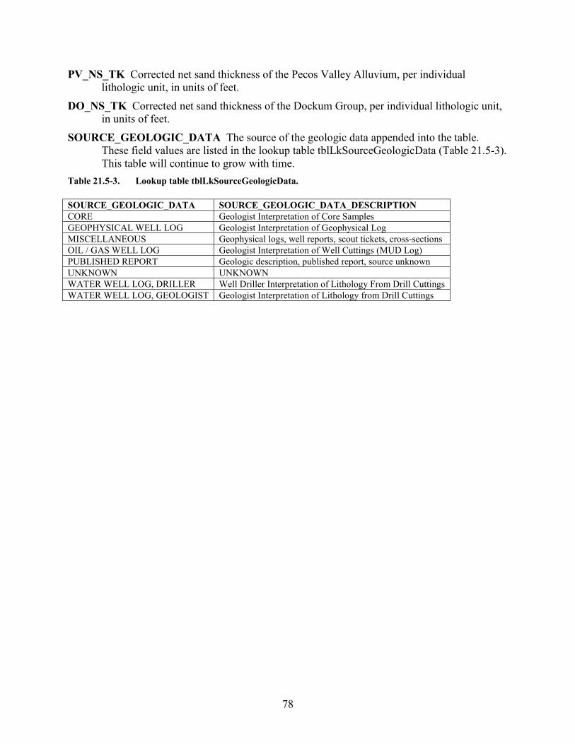
78
PV_NS_TK Corrected net sand thickness of the Pecos Valley Alluvium, per individual lithologic unit, in units of feet.
DO_NS_TK Corrected net sand thickness of the Dockum Group, per individual lithologic unit, in units of feet.
SOURCE_GEOLOGIC_DATA The source of the geologic data appended into the table. These field values are listed in the lookup table tblLkSourceGeologicData (Table 21.5-3). This table will continue to grow with time.
Table 21.5-3. Lookup table tblLkSourceGeologicData. SOURCE_GEOLOGIC_DATA SOURCE_GEOLOGIC_DATA_DESCRIPTION CORE Geologist Interpretation of Core Samples GEOPHYSICAL WELL LOG Geologist Interpretation of Geophysical Log MISCELLANEOUS Geophysical logs, well reports, scout tickets, cross-sections OIL / GAS WELL LOG Geologist Interpretation of Well Cuttings (MUD Log) PUBLISHED REPORT Geologic description, published report, source unknown UNKNOWN UNKNOWN WATER WELL LOG, DRILLER Well Driller Interpretation of Lithology From Drill Cuttings WATER WELL LOG, GEOLOGIST Geologist Interpretation of Lithology from Drill Cuttings
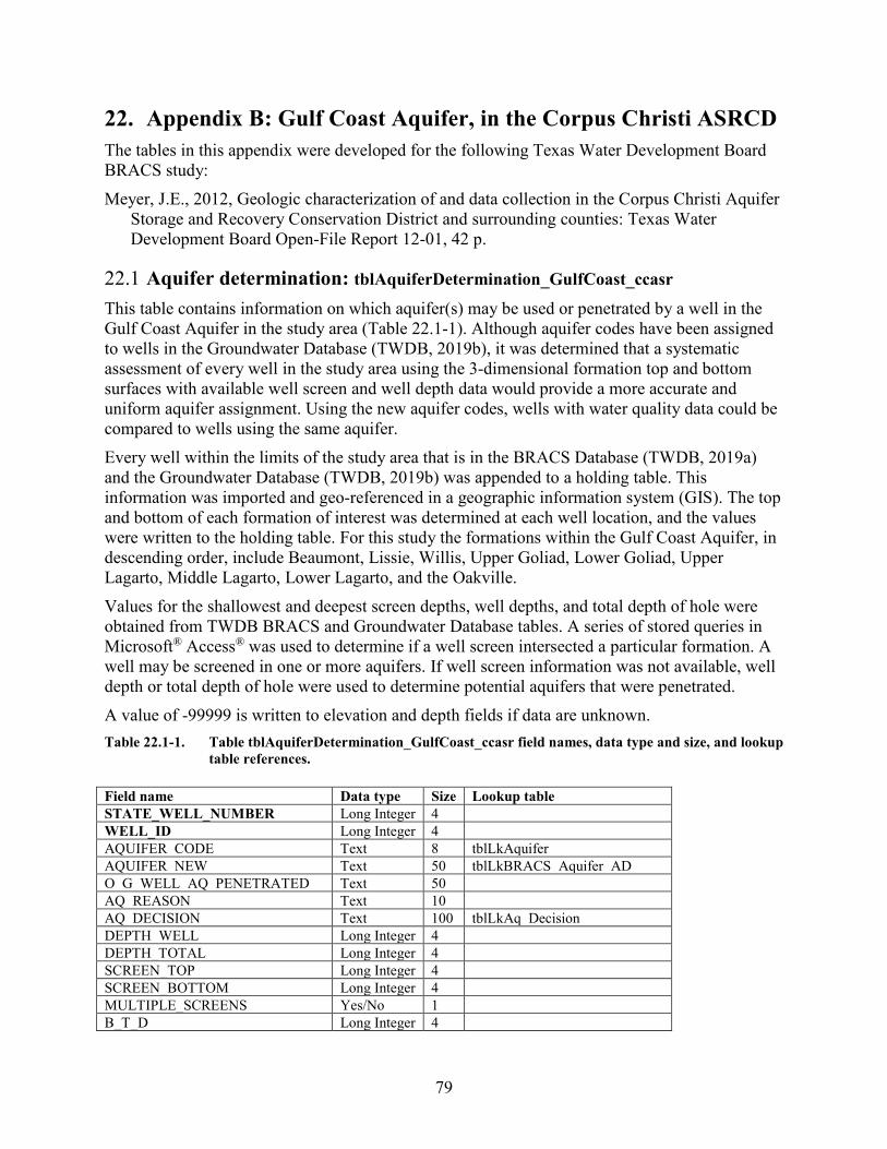
79
22. Appendix B: Gulf Coast Aquifer, in the Corpus Christi ASRCD The tables in this appendix were developed for the following Texas Water Development Board BRACS study: Meyer, J.E., 2012, Geologic characterization of and data collection in the Corpus Christi Aquifer
Storage and Recovery Conservation District and surrounding counties: Texas Water Development Board Open-File Report 12-01, 42 p.
22.1 Aquifer determination: tblAquiferDetermination_GulfCoast_ccasr This table contains information on which aquifer(s) may be used or penetrated by a well in the Gulf Coast Aquifer in the study area (Table 22.1-1). Although aquifer codes have been assigned to wells in the Groundwater Database (TWDB, 2019b), it was determined that a systematic assessment of every well in the study area using the 3-dimensional formation top and bottom surfaces with available well screen and well depth data would provide a more accurate and uniform aquifer assignment. Using the new aquifer codes, wells with water quality data could be compared to wells using the same aquifer. Every well within the limits of the study area that is in the BRACS Database (TWDB, 2019a) and the Groundwater Database (TWDB, 2019b) was appended to a holding table. This information was imported and geo-referenced in a geographic information system (GIS). The top and bottom of each formation of interest was determined at each well location, and the values were written to the holding table. For this study the formations within the Gulf Coast Aquifer, in descending order, include Beaumont, Lissie, Willis, Upper Goliad, Lower Goliad, Upper Lagarto, Middle Lagarto, Lower Lagarto, and the Oakville. Values for the shallowest and deepest screen depths, well depths, and total depth of hole were obtained from TWDB BRACS and Groundwater Database tables. A series of stored queries in Microsoft® Access® was used to determine if a well screen intersected a particular formation. A well may be screened in one or more aquifers. If well screen information was not available, well depth or total depth of hole were used to determine potential aquifers that were penetrated. A value of -99999 is written to elevation and depth fields if data are unknown. Table 22.1-1. Table tblAquiferDetermination_GulfCoast_ccasr field names, data type and size, and lookup
table references. Field name Data type Size Lookup table STATE_WELL_NUMBER Long Integer 4 WELL_ID Long Integer 4 AQUIFER_CODE Text 8 tblLkAquifer AQUIFER_NEW Text 50 tblLkBRACS_Aquifer_AD O_G_WELL_AQ_PENETRATED Text 50 AQ_REASON Text 10 AQ_DECISION Text 100 tblLkAq_Decision DEPTH_WELL Long Integer 4 DEPTH_TOTAL Long Integer 4 SCREEN_TOP Long Integer 4 SCREEN_BOTTOM Long Integer 4 MULTIPLE_SCREENS Yes/No 1 B_T_D Long Integer 4
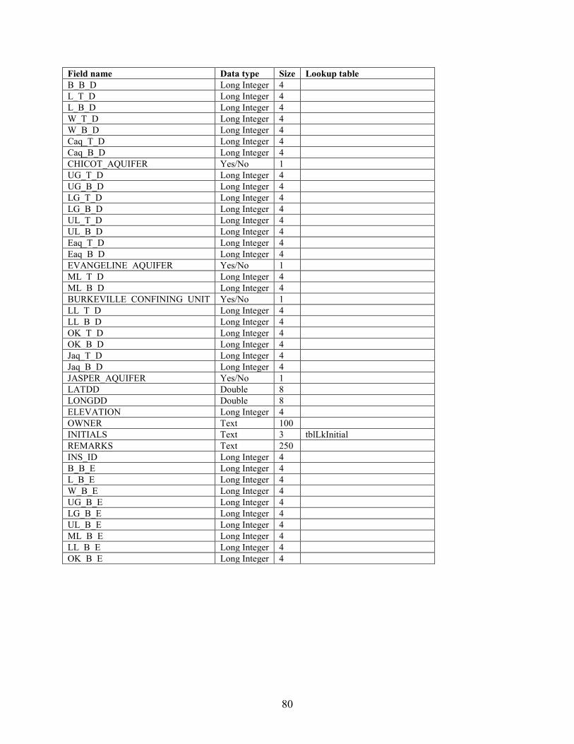
80
Field name Data type Size Lookup table B_B_D Long Integer 4 L_T_D Long Integer 4 L_B_D Long Integer 4 W_T_D Long Integer 4 W_B_D Long Integer 4 Caq_T_D Long Integer 4 Caq_B_D Long Integer 4 CHICOT_AQUIFER Yes/No 1 UG_T_D Long Integer 4 UG_B_D Long Integer 4 LG_T_D Long Integer 4 LG_B_D Long Integer 4 UL_T_D Long Integer 4 UL_B_D Long Integer 4 Eaq_T_D Long Integer 4 Eaq_B_D Long Integer 4 EVANGELINE_AQUIFER Yes/No 1 ML_T_D Long Integer 4 ML_B_D Long Integer 4 BURKEVILLE_CONFINING_UNIT Yes/No 1 LL_T_D Long Integer 4 LL_B_D Long Integer 4 OK_T_D Long Integer 4 OK_B_D Long Integer 4 Jaq_T_D Long Integer 4 Jaq_B_D Long Integer 4 JASPER_AQUIFER Yes/No 1 LATDD Double 8 LONGDD Double 8 ELEVATION Long Integer 4 OWNER Text 100 INITIALS Text 3 tblLkInitial REMARKS Text 250 INS_ID Long Integer 4 B_B_E Long Integer 4 L_B_E Long Integer 4 W_B_E Long Integer 4 UG_B_E Long Integer 4 LG_B_E Long Integer 4 UL_B_E Long Integer 4 ML_B_E Long Integer 4 LL_B_E Long Integer 4 OK_B_E Long Integer 4
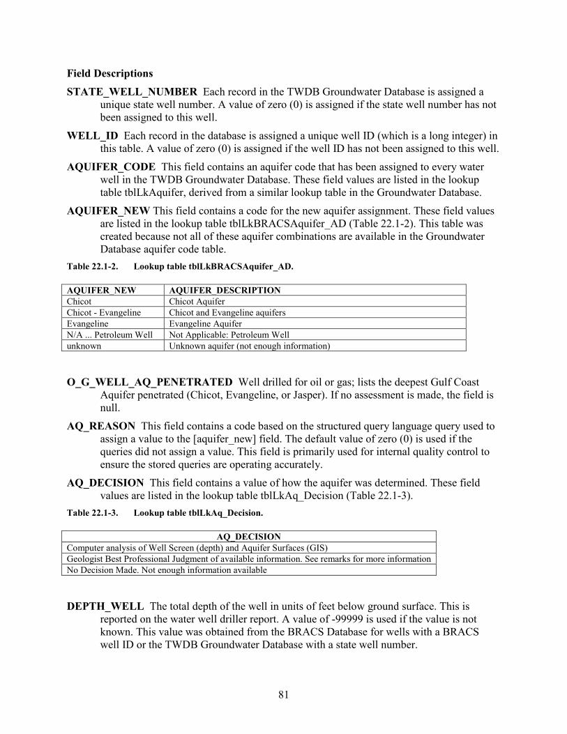
81
Field Descriptions STATE_WELL_NUMBER Each record in the TWDB Groundwater Database is assigned a
unique state well number. A value of zero (0) is assigned if the state well number has not been assigned to this well.
WELL_ID Each record in the database is assigned a unique well ID (which is a long integer) in this table. A value of zero (0) is assigned if the well ID has not been assigned to this well.
AQUIFER_CODE This field contains an aquifer code that has been assigned to every water well in the TWDB Groundwater Database. These field values are listed in the lookup table tblLkAquifer, derived from a similar lookup table in the Groundwater Database.
AQUIFER_NEW This field contains a code for the new aquifer assignment. These field values are listed in the lookup table tblLkBRACSAquifer_AD (Table 22.1-2). This table was created because not all of these aquifer combinations are available in the Groundwater Database aquifer code table.
Table 22.1-2. Lookup table tblLkBRACSAquifer_AD. AQUIFER_NEW AQUIFER_DESCRIPTION Chicot Chicot Aquifer Chicot - Evangeline Chicot and Evangeline aquifers Evangeline Evangeline Aquifer N/A ... Petroleum Well Not Applicable: Petroleum Well unknown Unknown aquifer (not enough information)
O_G_WELL_AQ_PENETRATED Well drilled for oil or gas; lists the deepest Gulf Coast
Aquifer penetrated (Chicot, Evangeline, or Jasper). If no assessment is made, the field is null.
AQ_REASON This field contains a code based on the structured query language query used to assign a value to the [aquifer_new] field. The default value of zero (0) is used if the queries did not assign a value. This field is primarily used for internal quality control to ensure the stored queries are operating accurately.
AQ_DECISION This field contains a value of how the aquifer was determined. These field values are listed in the lookup table tblLkAq_Decision (Table 22.1-3).
Table 22.1-3. Lookup table tblLkAq_Decision.
AQ_DECISION Computer analysis of Well Screen (depth) and Aquifer Surfaces (GIS) Geologist Best Professional Judgment of available information. See remarks for more information No Decision Made. Not enough information available
DEPTH_WELL The total depth of the well in units of feet below ground surface. This is
reported on the water well driller report. A value of -99999 is used if the value is not known. This value was obtained from the BRACS Database for wells with a BRACS well ID or the TWDB Groundwater Database with a state well number.
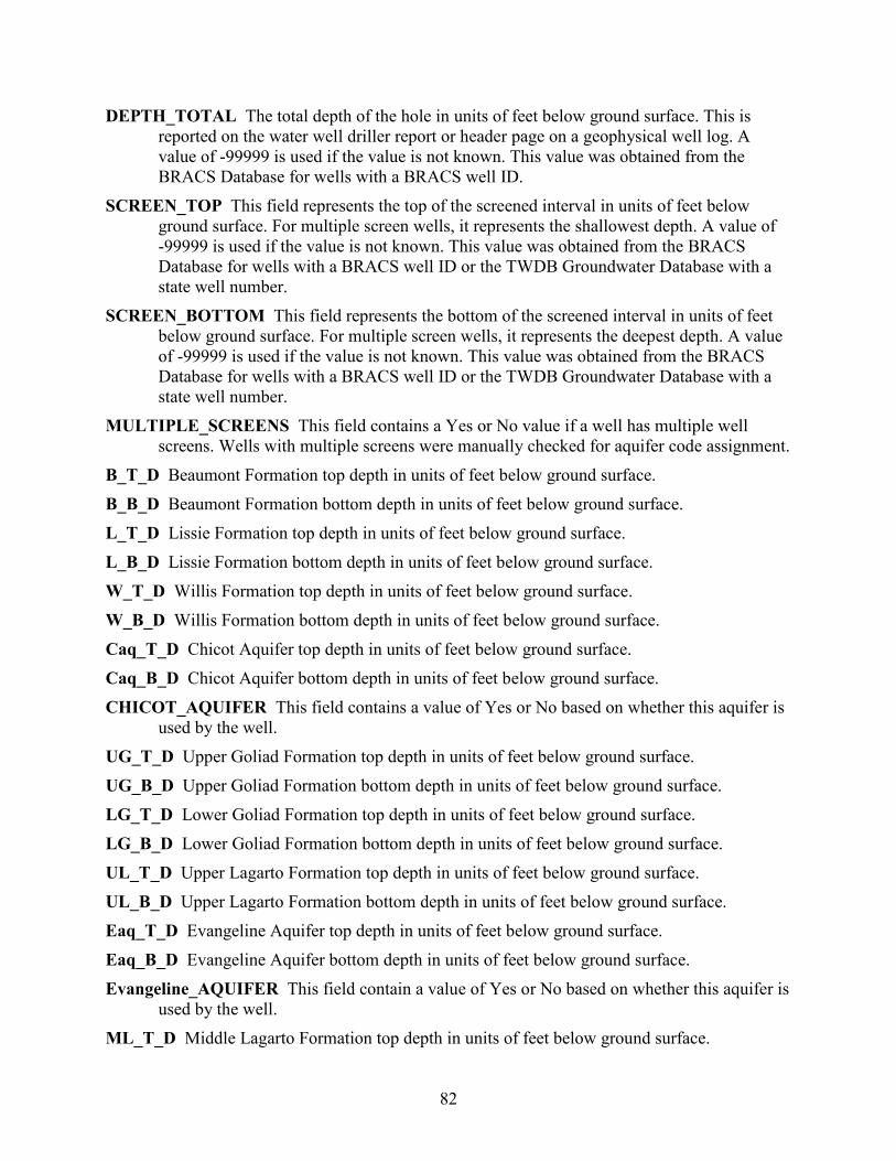
82
DEPTH_TOTAL The total depth of the hole in units of feet below ground surface. This is reported on the water well driller report or header page on a geophysical well log. A value of -99999 is used if the value is not known. This value was obtained from the BRACS Database for wells with a BRACS well ID.
SCREEN_TOP This field represents the top of the screened interval in units of feet below ground surface. For multiple screen wells, it represents the shallowest depth. A value of -99999 is used if the value is not known. This value was obtained from the BRACS Database for wells with a BRACS well ID or the TWDB Groundwater Database with a state well number.
SCREEN_BOTTOM This field represents the bottom of the screened interval in units of feet below ground surface. For multiple screen wells, it represents the deepest depth. A value of -99999 is used if the value is not known. This value was obtained from the BRACS Database for wells with a BRACS well ID or the TWDB Groundwater Database with a state well number.
MULTIPLE_SCREENS This field contains a Yes or No value if a well has multiple well screens. Wells with multiple screens were manually checked for aquifer code assignment.
B_T_D Beaumont Formation top depth in units of feet below ground surface. B_B_D Beaumont Formation bottom depth in units of feet below ground surface. L_T_D Lissie Formation top depth in units of feet below ground surface. L_B_D Lissie Formation bottom depth in units of feet below ground surface. W_T_D Willis Formation top depth in units of feet below ground surface. W_B_D Willis Formation bottom depth in units of feet below ground surface. Caq_T_D Chicot Aquifer top depth in units of feet below ground surface. Caq_B_D Chicot Aquifer bottom depth in units of feet below ground surface. CHICOT_AQUIFER This field contains a value of Yes or No based on whether this aquifer is
used by the well. UG_T_D Upper Goliad Formation top depth in units of feet below ground surface. UG_B_D Upper Goliad Formation bottom depth in units of feet below ground surface. LG_T_D Lower Goliad Formation top depth in units of feet below ground surface. LG_B_D Lower Goliad Formation bottom depth in units of feet below ground surface. UL_T_D Upper Lagarto Formation top depth in units of feet below ground surface. UL_B_D Upper Lagarto Formation bottom depth in units of feet below ground surface. Eaq_T_D Evangeline Aquifer top depth in units of feet below ground surface. Eaq_B_D Evangeline Aquifer bottom depth in units of feet below ground surface. Evangeline_AQUIFER This field contain a value of Yes or No based on whether this aquifer is
used by the well. ML_T_D Middle Lagarto Formation top depth in units of feet below ground surface.
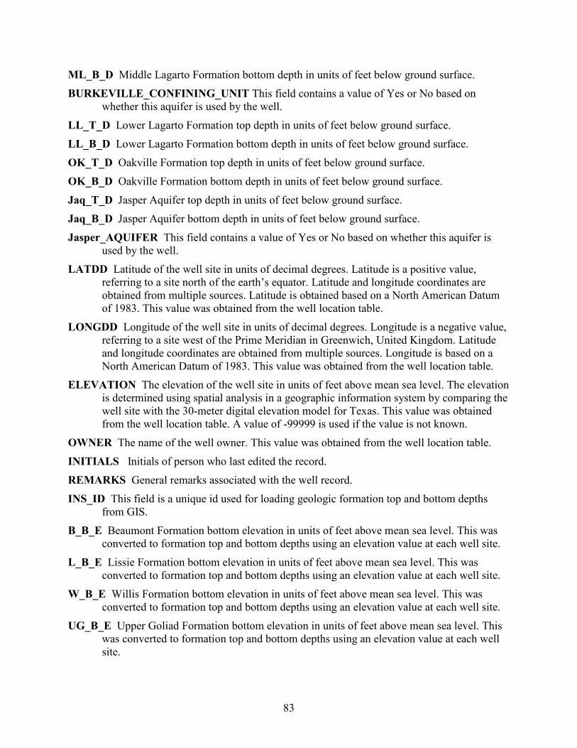
83
ML_B_D Middle Lagarto Formation bottom depth in units of feet below ground surface. BURKEVILLE_CONFINING_UNIT This field contains a value of Yes or No based on
whether this aquifer is used by the well. LL_T_D Lower Lagarto Formation top depth in units of feet below ground surface. LL_B_D Lower Lagarto Formation bottom depth in units of feet below ground surface. OK_T_D Oakville Formation top depth in units of feet below ground surface. OK_B_D Oakville Formation bottom depth in units of feet below ground surface. Jaq_T_D Jasper Aquifer top depth in units of feet below ground surface. Jaq_B_D Jasper Aquifer bottom depth in units of feet below ground surface. Jasper_AQUIFER This field contains a value of Yes or No based on whether this aquifer is
used by the well. LATDD Latitude of the well site in units of decimal degrees. Latitude is a positive value,
referring to a site north of the earth’s equator. Latitude and longitude coordinates are obtained from multiple sources. Latitude is obtained based on a North American Datum of 1983. This value was obtained from the well location table.
LONGDD Longitude of the well site in units of decimal degrees. Longitude is a negative value, referring to a site west of the Prime Meridian in Greenwich, United Kingdom. Latitude and longitude coordinates are obtained from multiple sources. Longitude is based on a North American Datum of 1983. This value was obtained from the well location table.
ELEVATION The elevation of the well site in units of feet above mean sea level. The elevation is determined using spatial analysis in a geographic information system by comparing the well site with the 30-meter digital elevation model for Texas. This value was obtained from the well location table. A value of -99999 is used if the value is not known.
OWNER The name of the well owner. This value was obtained from the well location table. INITIALS Initials of person who last edited the record. REMARKS General remarks associated with the well record. INS_ID This field is a unique id used for loading geologic formation top and bottom depths
from GIS. B_B_E Beaumont Formation bottom elevation in units of feet above mean sea level. This was
converted to formation top and bottom depths using an elevation value at each well site. L_B_E Lissie Formation bottom elevation in units of feet above mean sea level. This was
converted to formation top and bottom depths using an elevation value at each well site. W_B_E Willis Formation bottom elevation in units of feet above mean sea level. This was
converted to formation top and bottom depths using an elevation value at each well site. UG_B_E Upper Goliad Formation bottom elevation in units of feet above mean sea level. This
was converted to formation top and bottom depths using an elevation value at each well site.
84
LG_B_E Lower Goliad Formation bottom elevation in units of feet above mean sea level. This was converted to formation top and bottom depths using an elevation value at each well site.
UL_B_E Upper Lagarto Formation bottom elevation in units of feet above mean sea level. This was converted to formation top and bottom depths using an elevation value at each well site.
ML_B_E Middle Lagarto Formation bottom elevation in units of feet above mean sea level. This was converted to formation top and bottom depths using an elevation value at each well site.
LL_B_E Lower Lagarto Formation bottom elevation in units of feet above mean sea level. This was converted to formation top and bottom depths using an elevation value at each well site.
OK_B_E Oakville Formation bottom elevation in units of feet above mean sea level. This was converted to formation top and bottom depths using an elevation value at each well site.

85
22.2 Stratigraphic table for GIS import: gBRACS_ST_GC This table is created from information residing in the primary BRACS Database tables (Table 22.2-1). Well records are appended to this table and processed using a number of stored structured query language queries in Microsoft® Access®. This table is exported into a geographic information system (GIS) to spatially display geologic formation depth and elevation values at well sites. The point shape file is used to create 3-dimensional geologic surfaces and contour maps. Note: Formation depths have been adjusted for kelly bushing height, if known or applicable. Formation elevations have been calculated using formation depths (adjusted for kelly bushing height, if known or applicable) and well site elevation. A value of -99999 is written to elevation and depth fields if data are unknown. Table 22.2-1. Table gBRACS_ST_GC field names, data type and size, lookup table references, and source
table. Field name Data type Size Lookup table Source table WELL_ID Long Integer 4 tblWell_Location WELL_TYPE Text 50 tblLkWellType API_NUMBER Text 12
tblBracs_ForeignKey SW_NUM Long Integer 4 TRACK_NUM Long Integer 4 Q_NUM Text 16 SOURCE_WELL_DATA Text 250 tblLkSourceWellData
tblWell_Location
ELEVATION Long Integer 4 KELLY_BUSHING_HEIGHT Integer 2 DEPTH_TOTAL Long Integer 4 DEPTH_WELL Long Integer 4 LATDD Double 8 LONGDD Double 8 AGENCY Text 5 tblLkAgency COUNTY_NAME Text 13 B_T_D Long Integer 4
tblWell_Geology (Note: these fields are adjusted for kelly bushing height)
B_B_D Long Integer 4 B_TK Long Integer 4 B_GT Text 1 B_T_E Long Integer 4 B_B_E Long Integer 4 L_T_D Long Integer 4 L_B_D Long Integer 4 L_TK Long Integer 4 L_GT Text 1 L_T_E Long Integer 4 L_B_E Long Integer 4 W_T_D Long Integer 4 W_B_D Long Integer 4 W_TK Long Integer 4 W_GT Text 1 W_T_E Long Integer 4 W_B_E Long Integer 4 UG_T_D Long Integer 4
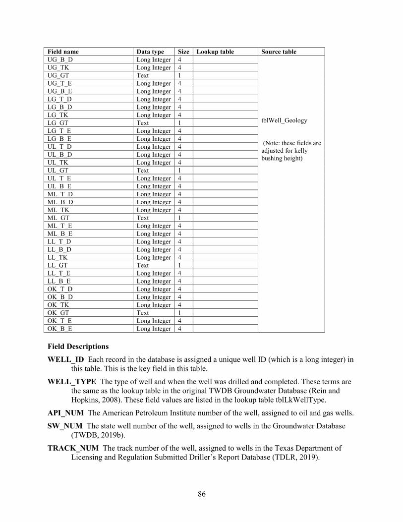
86
Field name Data type Size Lookup table Source table UG_B_D Long Integer 4
tblWell_Geology (Note: these fields are adjusted for kelly bushing height)
UG_TK Long Integer 4 UG_GT Text 1 UG_T_E Long Integer 4 UG_B_E Long Integer 4 LG_T_D Long Integer 4 LG_B_D Long Integer 4 LG_TK Long Integer 4 LG_GT Text 1 LG_T_E Long Integer 4 LG_B_E Long Integer 4 UL_T_D Long Integer 4 UL_B_D Long Integer 4 UL_TK Long Integer 4 UL_GT Text 1 UL_T_E Long Integer 4 UL_B_E Long Integer 4 ML_T_D Long Integer 4 ML_B_D Long Integer 4 ML_TK Long Integer 4 ML_GT Text 1 ML_T_E Long Integer 4 ML_B_E Long Integer 4 LL_T_D Long Integer 4 LL_B_D Long Integer 4 LL_TK Long Integer 4 LL_GT Text 1 LL_T_E Long Integer 4 LL_B_E Long Integer 4 OK_T_D Long Integer 4 OK_B_D Long Integer 4 OK_TK Long Integer 4 OK_GT Text 1 OK_T_E Long Integer 4 OK_B_E Long Integer 4 Field Descriptions WELL_ID Each record in the database is assigned a unique well ID (which is a long integer) in
this table. This is the key field in this table. WELL_TYPE The type of well and when the well was drilled and completed. These terms are
the same as the lookup table in the original TWDB Groundwater Database (Rein and Hopkins, 2008). These field values are listed in the lookup table tblLkWellType.
API_NUM The American Petroleum Institute number of the well, assigned to oil and gas wells. SW_NUM The state well number of the well, assigned to wells in the Groundwater Database
(TWDB, 2019b). TRACK_NUM The track number of the well, assigned to wells in the Texas Department of
Licensing and Regulation Submitted Driller’s Report Database (TDLR, 2019).
87
WS_NUM The water source code, assigned to wells by the Texas Commission on Environmental Quality public water system program.
Q_NUM The Q number assigned to wells by the Railroad Commission of Texas Groundwater Advisory Unit.
SOURCE_WELL_DATA Each well record is assigned the source of the well information. In some cases multiple sources exist; in this case, the source of the geophysical well log or water well driller report takes precedence. These field values are listed in the lookup table tblLkSourceWellData (Table 2-5).
ELEVATION The elevation of the well site in units of feet above mean sea level. The elevation is determined using spatial analysis in a geographic information system by comparing the well site with the 30-meter digital elevation model for Texas.
KELLY_BUSHING_HEIGHT The height of the drilling rig kelly bushing (KB) used as a measuring point for all subsequent logging. The units are in feet above ground surface. This value is stored as an integer. The term is synonymous with rig floor (RF), derrick floor (DF), rotary table (RT), and drive bushing (DB). This value is usually located on the geophysical well log header page as a unique value, or it must be calculated from the values of elevation of the ground surface and elevation of the kelly bushing. The default value for this field is zero (0) if the measure point of logging is ground surface or if the kelly bushing height is unknown.
DEPTH_TOTAL The total depth of the hole in units of feet below ground surface. This is reported on the water well driller report or header page on a geophysical well log. A value of -99999 is used if the value is not known.
DEPTH_WELL The total depth of the well in units of feet below ground surface. This is reported on the water well driller report. A value of -99999 is used if the value is not known.
LATDD Latitude of the well site in units of decimal degrees. Latitude is a positive value, referring to a site north of the earth’s equator. Latitude and longitude coordinates are obtained from multiple sources. Latitude is obtained is based on a North American Datum of 1983.
LONGDD Longitude of the well site in units of decimal degrees. Longitude is a negative value, referring to a site west of the Prime Meridian in Greenwich, United Kingdom. Latitude and longitude coordinates are obtained from multiple sources. Longitude is based on a North American Datum of 1983.
AGENCY The agency that collected the latitude and longitude coordinates of the well site. These field values are listed in the lookup table tblLkAgency (Table 2-5).
B_T_D Beaumont Formation top depth in units of feet below ground surface. B_B_D Beaumont Formation bottom depth in units of feet below ground surface. B_TK Beaumont Formation thickness in units of feet. B_GT Greater than symbol (>) represents well only partially penetrates the Beaumont
Formation.
88
B_T_E Beaumont Formation top elevation in units of feet above mean sea level. B_B_E Beaumont Formation bottom elevation in units of feet above mean sea level. L_T_D Lissie Formation top depth in units of feet below ground surface. L_B_D Lissie Formation bottom depth in units of feet below ground surface. L_TK Lissie Formation thickness in units of feet. L_GT Greater than symbol (>) represents well only partially penetrates the Lissie Formation. L_T_E Lissie Formation top elevation in units of feet above mean sea level. L_B_E Lissie Formation bottom elevation in units of feet above mean sea level. W_T_D Willis Formation top depth in units of feet below ground surface. W_B_D Willis Formation bottom depth in units of feet below ground surface. W_TK Willis Formation thickness in units of feet. W_GT Greater than symbol (>) represents well only partially penetrates the Willis Formation. W_T_E Willis Formation top elevation in units of feet above mean sea level. W_B_E Willis Formation bottom elevation in units of feet above mean sea level. UG_T_D Upper Goliad Formation top depth in units of feet below ground surface. UG_B_D Upper Goliad Formation bottom depth in units of feet below ground surface. UG_TK Upper Goliad Formation thickness in units of feet. UG_GT Greater than symbol (>) represents well only partially penetrates the Upper Goliad
Formation. UG_T_E Upper Goliad Formation top elevation in units of feet above mean sea level. UG_B_E Upper Goliad Formation bottom elevation in units of feet above mean sea level. LG_T_D Lower Goliad Formation top depth in units of feet below ground surface. LG_B_D Lower Goliad Formation bottom depth in units of feet below ground surface. LG_TK Lower Goliad Formation thickness in units of feet. LG_GT Greater than symbol (>) represents well only partially penetrates the Lower Goliad
Formation. LG_T_E Lower Goliad Formation top elevation in units of feet above mean sea level. LG_B_E Lower Goliad Formation bottom elevation in units of feet above mean sea level. UL_T_D Upper Lagarto Formation top depth in units of feet below ground surface. UL_B_D Upper Lagarto Formation bottom depth in units of feet below ground surface. UL_TK Upper Lagarto Formation thickness in units of feet. UL_GT Greater than symbol (>) represents well only partially penetrates the Upper Lagarto
Formation.
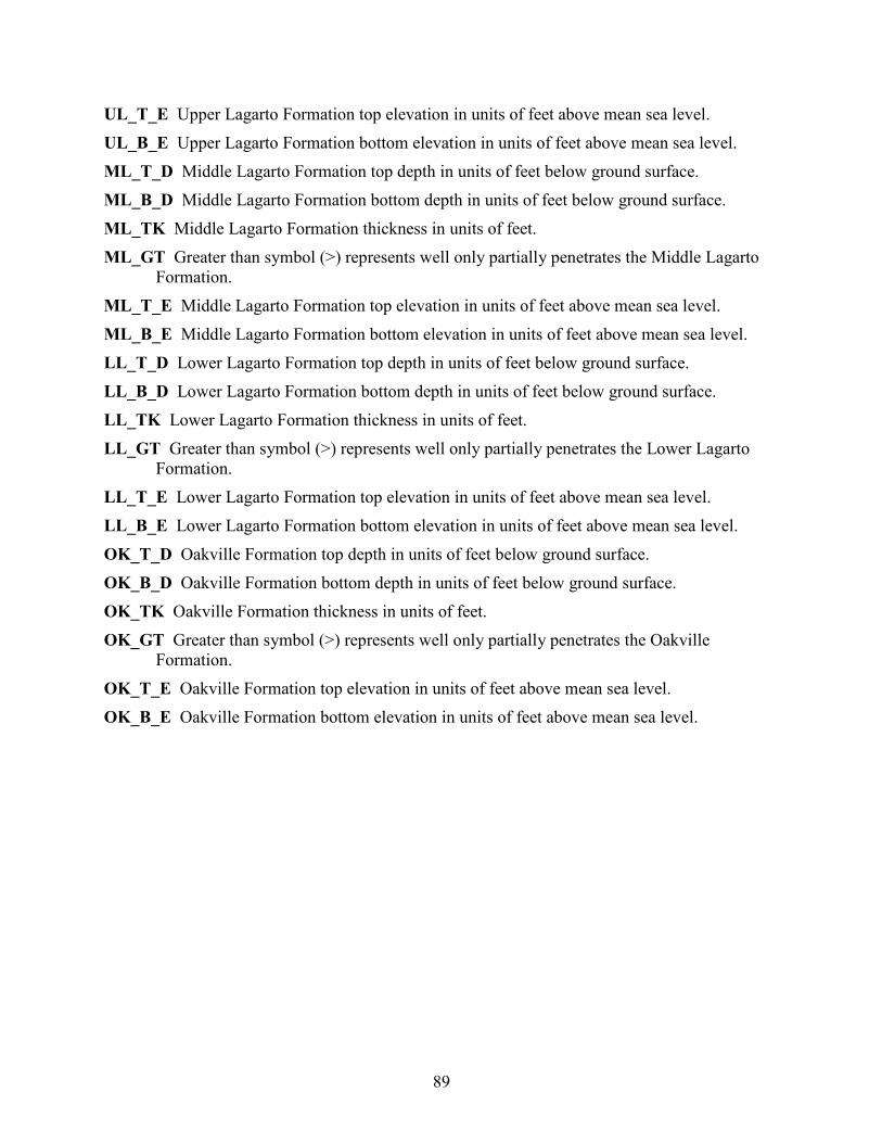
89
UL_T_E Upper Lagarto Formation top elevation in units of feet above mean sea level. UL_B_E Upper Lagarto Formation bottom elevation in units of feet above mean sea level. ML_T_D Middle Lagarto Formation top depth in units of feet below ground surface. ML_B_D Middle Lagarto Formation bottom depth in units of feet below ground surface. ML_TK Middle Lagarto Formation thickness in units of feet. ML_GT Greater than symbol (>) represents well only partially penetrates the Middle Lagarto
Formation. ML_T_E Middle Lagarto Formation top elevation in units of feet above mean sea level. ML_B_E Middle Lagarto Formation bottom elevation in units of feet above mean sea level. LL_T_D Lower Lagarto Formation top depth in units of feet below ground surface. LL_B_D Lower Lagarto Formation bottom depth in units of feet below ground surface. LL_TK Lower Lagarto Formation thickness in units of feet. LL_GT Greater than symbol (>) represents well only partially penetrates the Lower Lagarto
Formation. LL_T_E Lower Lagarto Formation top elevation in units of feet above mean sea level. LL_B_E Lower Lagarto Formation bottom elevation in units of feet above mean sea level. OK_T_D Oakville Formation top depth in units of feet below ground surface. OK_B_D Oakville Formation bottom depth in units of feet below ground surface. OK_TK Oakville Formation thickness in units of feet. OK_GT Greater than symbol (>) represents well only partially penetrates the Oakville
Formation. OK_T_E Oakville Formation top elevation in units of feet above mean sea level. OK_B_E Oakville Formation bottom elevation in units of feet above mean sea level.
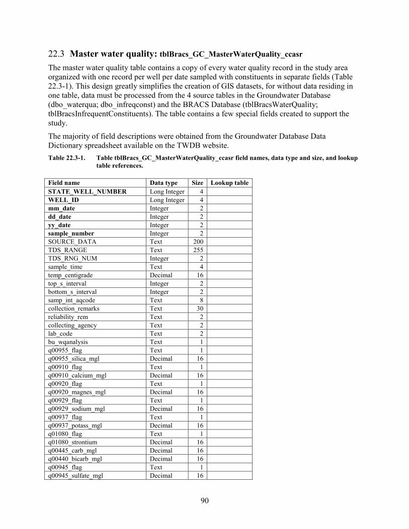
90
22.3 Master water quality: tblBracs_GC_MasterWaterQuality_ccasr The master water quality table contains a copy of every water quality record in the study area organized with one record per well per date sampled with constituents in separate fields (Table 22.3-1). This design greatly simplifies the creation of GIS datasets, for without data residing in one table, data must be processed from the 4 source tables in the Groundwater Database (dbo_waterqua; dbo_infreqconst) and the BRACS Database (tblBracsWaterQuality; tblBracsInfrequentConstituents). The table contains a few special fields created to support the study. The majority of field descriptions were obtained from the Groundwater Database Data Dictionary spreadsheet available on the TWDB website. Table 22.3-1. Table tblBracs_GC_MasterWaterQuality_ccasr field names, data type and size, and lookup
table references. Field name Data type Size Lookup table STATE_WELL_NUMBER Long Integer 4
WELL_ID Long Integer 4
mm_date Integer 2
dd_date Integer 2
yy_date Integer 2
sample_number Integer 2
SOURCE_DATA Text 200
TDS_RANGE Text 255
TDS_RNG_NUM Integer 2
sample_time Text 4
temp_centigrade Decimal 16
top_s_interval Integer 2
bottom_s_interval Integer 2
samp_int_aqcode Text 8
collection_remarks Text 30
reliability_rem Text 2
collecting_agency Text 2
lab_code Text 2
bu_wqanalysis Text 1
q00955_flag Text 1
q00955_silica_mgl Decimal 16
q00910_flag Text 1
q00910_calcium_mgl Decimal 16
q00920_flag Text 1
q00920_magnes_mgl Decimal 16
q00929_flag Text 1
q00929_sodium_mgl Decimal 16
q00937_flag Text 1
q00937_potass_mgl Decimal 16
q01080_flag Text 1
q01080_strontium Decimal 16
q00445_carb_mgl Decimal 16
q00440_bicarb_mgl Decimal 16
q00945_flag Text 1
q00945_sulfate_mgl Decimal 16
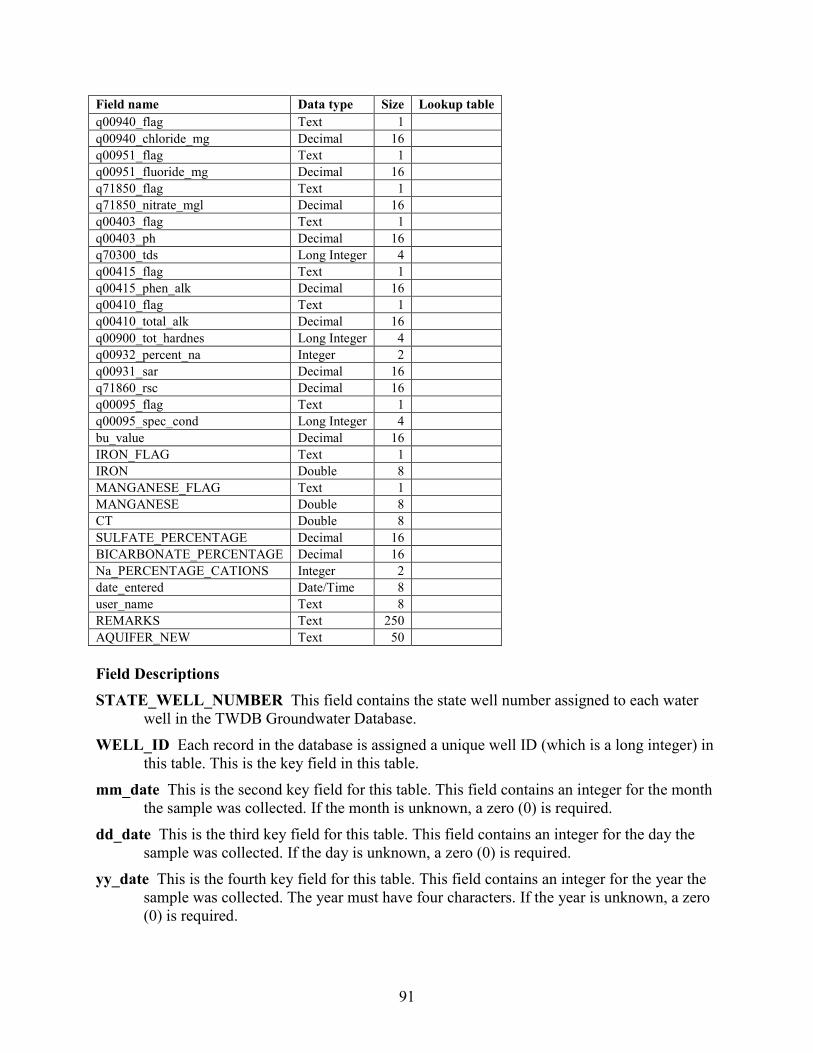
91
Field name Data type Size Lookup table q00940_flag Text 1
q00940_chloride_mg Decimal 16
q00951_flag Text 1
q00951_fluoride_mg Decimal 16
q71850_flag Text 1
q71850_nitrate_mgl Decimal 16
q00403_flag Text 1
q00403_ph Decimal 16
q70300_tds Long Integer 4
q00415_flag Text 1
q00415_phen_alk Decimal 16
q00410_flag Text 1
q00410_total_alk Decimal 16
q00900_tot_hardnes Long Integer 4
q00932_percent_na Integer 2
q00931_sar Decimal 16
q71860_rsc Decimal 16
q00095_flag Text 1
q00095_spec_cond Long Integer 4
bu_value Decimal 16
IRON_FLAG Text 1
IRON Double 8
MANGANESE_FLAG Text 1
MANGANESE Double 8
CT Double 8
SULFATE_PERCENTAGE Decimal 16
BICARBONATE_PERCENTAGE Decimal 16
Na_PERCENTAGE_CATIONS Integer 2
date_entered Date/Time 8
user_name Text 8
REMARKS Text 250
AQUIFER_NEW Text 50 Field Descriptions STATE_WELL_NUMBER This field contains the state well number assigned to each water
well in the TWDB Groundwater Database. WELL_ID Each record in the database is assigned a unique well ID (which is a long integer) in
this table. This is the key field in this table. mm_date This is the second key field for this table. This field contains an integer for the month
the sample was collected. If the month is unknown, a zero (0) is required. dd_date This is the third key field for this table. This field contains an integer for the day the
sample was collected. If the day is unknown, a zero (0) is required. yy_date This is the fourth key field for this table. This field contains an integer for the year the
sample was collected. The year must have four characters. If the year is unknown, a zero (0) is required.

92
sample_number This is the fifth key field for this table. This is an integer referring to a sample number, since more than one sample may be taken on the same day. It consists of an integer beginning with one for the first record of a well and increases by a value of one for each new record.
SOURCE_DATA This field contains a reference to the source of the information; for example, the report number and table or page number.
TDS_RANGE This field contains a value representing the range of total dissolved solids content to be used for GIS analysis of brackish groundwater resources in Texas. The ranges include values, in milligrams per liter, of: 0 – 999; 1000 – 2999; 3000 – 9999; and > 10000.
TDS_RNG_NUM This field contains an integer value representing the range of total dissolved solids content to be used for GIS analysis of brackish groundwater resources in Texas. The ranges include values, in milligrams per liter, of: 1 = 0 – 999; 2 = 1000 – 2999; 3 = 3000 – 9999; and 4 = > 10000.
sample_time This field contains the time the sample was collected using four digits in the format of a 24-hour time period (for example, 8:45 a.m. is 0845; 4:21 p.m. is 1621).
temp_centigrade Temperature of water sample in Celsius (field measurement). top_s_interval Top interval of formation where sample was collected in units of feet below
ground surface (only for multiple completion wells). bottom_s_interval Bottom interval of formation where sample was collected in units of feet
below ground surface (only for multiple completion wells). samp_int_aqcode Aquifer code for the sampled interval (only for multiple completion wells). collection_remarks Remarks about the sample collected. reliability_rem Indicates the process used to collect the sample. collecting_agency Identifies the entity that collected the sample. lab_code Identifies the lab used to analyze the sample. bu_wqanalysis Indicates whether the analysis of the sample is Balanced (B) or Unbalanced (U). q00955_flag Used to identify constituent concentrations below the lab's detection limits. q00955_silica_mgl Silica, dissolved, in units of milligrams per liter. q00910_flag Used to identify constituent concentrations below the lab's detection limits. q00910_calcium_mgl Calcium, dissolved, in units of milligrams per liter. q00920_flag Used to identify constituent concentrations below the lab's detection limits. q00920_magnes_mgl Magnesium, dissolved, in units of milligrams per liter. q00929_flag Used to identify constituent concentrations below the lab's detection limits. q00929_sodium_mgl Sodium, dissolved, in units of milligrams per liter. q00937_flag Used to identify constituent concentrations below the lab's detection limits.
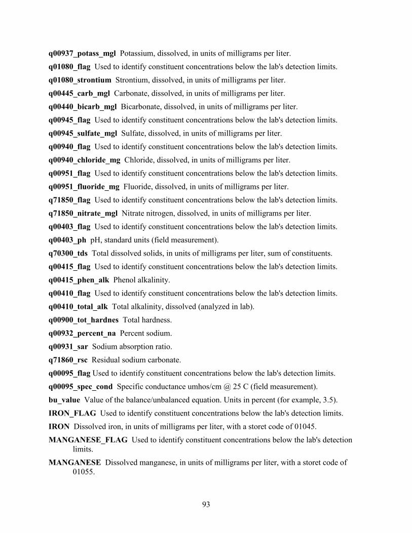
93
q00937_potass_mgl Potassium, dissolved, in units of milligrams per liter. q01080_flag Used to identify constituent concentrations below the lab's detection limits. q01080_strontium Strontium, dissolved, in units of milligrams per liter. q00445_carb_mgl Carbonate, dissolved, in units of milligrams per liter. q00440_bicarb_mgl Bicarbonate, dissolved, in units of milligrams per liter. q00945_flag Used to identify constituent concentrations below the lab's detection limits. q00945_sulfate_mgl Sulfate, dissolved, in units of milligrams per liter. q00940_flag Used to identify constituent concentrations below the lab's detection limits. q00940_chloride_mg Chloride, dissolved, in units of milligrams per liter. q00951_flag Used to identify constituent concentrations below the lab's detection limits. q00951_fluoride_mg Fluoride, dissolved, in units of milligrams per liter. q71850_flag Used to identify constituent concentrations below the lab's detection limits. q71850_nitrate_mgl Nitrate nitrogen, dissolved, in units of milligrams per liter. q00403_flag Used to identify constituent concentrations below the lab's detection limits. q00403_ph pH, standard units (field measurement). q70300_tds Total dissolved solids, in units of milligrams per liter, sum of constituents. q00415_flag Used to identify constituent concentrations below the lab's detection limits. q00415_phen_alk Phenol alkalinity. q00410_flag Used to identify constituent concentrations below the lab's detection limits. q00410_total_alk Total alkalinity, dissolved (analyzed in lab). q00900_tot_hardnes Total hardness. q00932_percent_na Percent sodium. q00931_sar Sodium absorption ratio. q71860_rsc Residual sodium carbonate. q00095_flag Used to identify constituent concentrations below the lab's detection limits. q00095_spec_cond Specific conductance umhos/cm @ 25 C (field measurement). bu_value Value of the balance/unbalanced equation. Units in percent (for example, 3.5). IRON_FLAG Used to identify constituent concentrations below the lab's detection limits. IRON Dissolved iron, in units of milligrams per liter, with a storet code of 01045. MANGANESE_FLAG Used to identify constituent concentrations below the lab's detection
limits. MANGANESE Dissolved manganese, in units of milligrams per liter, with a storet code of
01055.
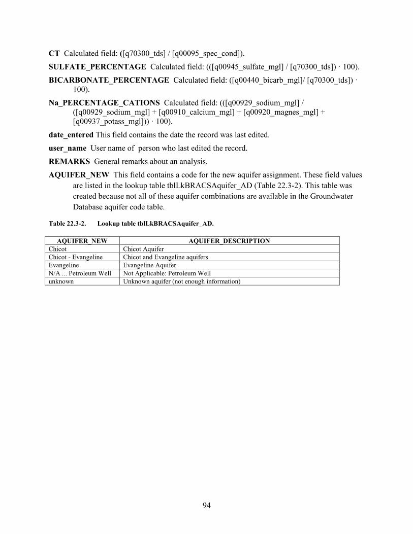
94
CT Calculated field: ([q70300_tds] / [q00095_spec_cond]). SULFATE_PERCENTAGE Calculated field: (([q00945_sulfate_mgl] / [q70300_tds]) · 100). BICARBONATE_PERCENTAGE Calculated field: ([q00440_bicarb_mgl]/ [q70300_tds]) ·
100). Na_PERCENTAGE_CATIONS Calculated field: (([q00929_sodium_mgl] /
([q00929_sodium_mgl] + [q00910_calcium_mgl] + [q00920_magnes_mgl] + [q00937_potass_mgl])) · 100).
date_entered This field contains the date the record was last edited. user_name User name of person who last edited the record. REMARKS General remarks about an analysis. AQUIFER_NEW This field contains a code for the new aquifer assignment. These field values
are listed in the lookup table tblLkBRACSAquifer_AD (Table 22.3-2). This table was created because not all of these aquifer combinations are available in the Groundwater Database aquifer code table.
Table 22.3-2. Lookup table tblLkBRACSAquifer_AD.
AQUIFER_NEW AQUIFER_DESCRIPTION Chicot Chicot Aquifer Chicot - Evangeline Chicot and Evangeline aquifers Evangeline Evangeline Aquifer N/A ... Petroleum Well Not Applicable: Petroleum Well unknown Unknown aquifer (not enough information)
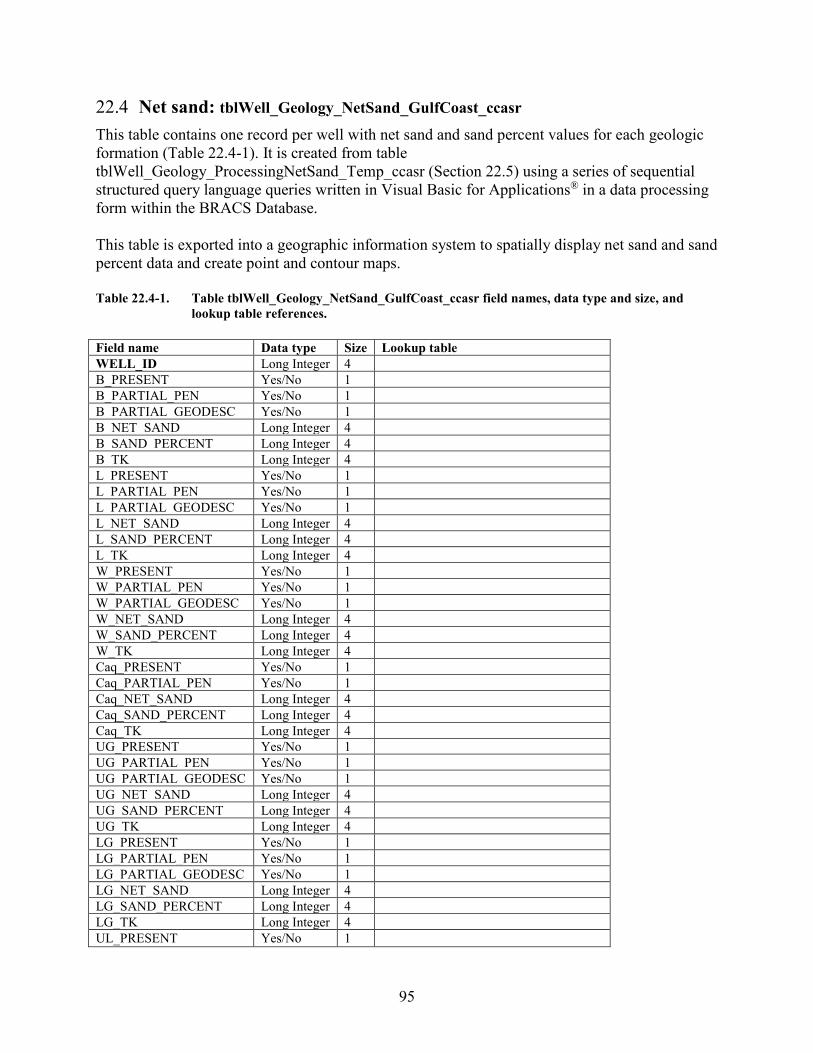
95
22.4 Net sand: tblWell_Geology_NetSand_GulfCoast_ccasr This table contains one record per well with net sand and sand percent values for each geologic formation (Table 22.4-1). It is created from table tblWell_Geology_ProcessingNetSand_Temp_ccasr (Section 22.5) using a series of sequential structured query language queries written in Visual Basic for Applications® in a data processing form within the BRACS Database. This table is exported into a geographic information system to spatially display net sand and sand percent data and create point and contour maps. Table 22.4-1. Table tblWell_Geology_NetSand_GulfCoast_ccasr field names, data type and size, and
lookup table references. Field name Data type Size Lookup table WELL_ID Long Integer 4 B_PRESENT Yes/No 1 B_PARTIAL_PEN Yes/No 1 B_PARTIAL_GEODESC Yes/No 1 B_NET_SAND Long Integer 4 B_SAND_PERCENT Long Integer 4 B_TK Long Integer 4 L_PRESENT Yes/No 1 L_PARTIAL_PEN Yes/No 1 L_PARTIAL_GEODESC Yes/No 1 L_NET_SAND Long Integer 4 L_SAND_PERCENT Long Integer 4 L_TK Long Integer 4 W_PRESENT Yes/No 1 W_PARTIAL_PEN Yes/No 1 W_PARTIAL_GEODESC Yes/No 1 W_NET_SAND Long Integer 4 W_SAND_PERCENT Long Integer 4 W_TK Long Integer 4 Caq_PRESENT Yes/No 1 Caq_PARTIAL_PEN Yes/No 1 Caq_NET_SAND Long Integer 4 Caq_SAND_PERCENT Long Integer 4 Caq_TK Long Integer 4 UG_PRESENT Yes/No 1 UG_PARTIAL_PEN Yes/No 1 UG_PARTIAL_GEODESC Yes/No 1 UG_NET_SAND Long Integer 4 UG_SAND_PERCENT Long Integer 4 UG_TK Long Integer 4 LG_PRESENT Yes/No 1 LG_PARTIAL_PEN Yes/No 1 LG_PARTIAL_GEODESC Yes/No 1 LG_NET_SAND Long Integer 4 LG_SAND_PERCENT Long Integer 4 LG_TK Long Integer 4 UL_PRESENT Yes/No 1
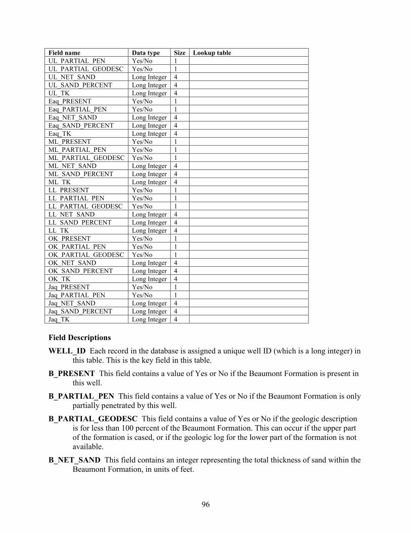
96
Field name Data type Size Lookup table UL_PARTIAL_PEN Yes/No 1 UL_PARTIAL_GEODESC Yes/No 1 UL_NET_SAND Long Integer 4 UL_SAND_PERCENT Long Integer 4 UL_TK Long Integer 4 Eaq_PRESENT Yes/No 1 Eaq_PARTIAL_PEN Yes/No 1 Eaq_NET_SAND Long Integer 4 Eaq_SAND_PERCENT Long Integer 4 Eaq_TK Long Integer 4 ML_PRESENT Yes/No 1 ML_PARTIAL_PEN Yes/No 1 ML_PARTIAL_GEODESC Yes/No 1 ML_NET_SAND Long Integer 4 ML_SAND_PERCENT Long Integer 4 ML_TK Long Integer 4 LL_PRESENT Yes/No 1 LL_PARTIAL_PEN Yes/No 1 LL_PARTIAL_GEODESC Yes/No 1 LL_NET_SAND Long Integer 4 LL_SAND_PERCENT Long Integer 4 LL_TK Long Integer 4 OK_PRESENT Yes/No 1 OK_PARTIAL_PEN Yes/No 1 OK_PARTIAL_GEODESC Yes/No 1 OK_NET_SAND Long Integer 4 OK_SAND_PERCENT Long Integer 4 OK_TK Long Integer 4 Jaq_PRESENT Yes/No 1 Jaq_PARTIAL_PEN Yes/No 1 Jaq_NET_SAND Long Integer 4 Jaq_SAND_PERCENT Long Integer 4 Jaq_TK Long Integer 4 Field Descriptions WELL_ID Each record in the database is assigned a unique well ID (which is a long integer) in
this table. This is the key field in this table. B_PRESENT This field contains a value of Yes or No if the Beaumont Formation is present in
this well. B_PARTIAL_PEN This field contains a value of Yes or No if the Beaumont Formation is only
partially penetrated by this well. B_PARTIAL_GEODESC This field contains a value of Yes or No if the geologic description
is for less than 100 percent of the Beaumont Formation. This can occur if the upper part of the formation is cased, or if the geologic log for the lower part of the formation is not available.
B_NET_SAND This field contains an integer representing the total thickness of sand within the Beaumont Formation, in units of feet.
97
B_SAND_PERCENT The percent of sand within the Beaumont Formation, calculated field: (([B_NET_SAND] / [B_TK]) · 100).
B_TK Beaumont Formation thickness, calculated field: ([B_B_D] - [B_T_D]). The units are feet.
L_PRESENT This field contains a value of Yes or No if the Lissie Formation is present in this well.
L_PARTIAL_PEN This field contains a value of Yes or No if the Lissie Formation is only partially penetrated by this well.
L_PARTIAL_GEODESC This field contains a value of Yes or No if the geologic description is for less than 100 percent of the Lissie Formation. This can occur if the upper part of the formation is cased, or if the geologic log for the lower part of the formation is not available.
L_NET_SAND This field contains an integer representing the total thickness of sand within the Lissie Formation, in units of feet.
L_SAND_PERCENT The percent of sand within the Lissie Formation, calculated field: (([L_NET_SAND] / [L_TK]) · 100).
L_TK Lissie Formation thickness, calculated field: ([L_B_D] - [L_T_D]). The units are feet. W_PRESENT This field contains a value of Yes or No if the Willis Formation is present in this
well. W_PARTIAL_PEN This field contains a value of Yes or No if the Willis Formation is only
partially penetrated by this well. W_PARTIAL_GEODESC This field contains a value of Yes or No if the geologic description
is for less than 100 percent of the Willis Formation. This can occur if the upper part of the formation is cased, or if the geologic log for the lower part of the formation is not available.
W_NET_SAND This field contains an integer representing the total thickness of sand within the Willis Formation, in units of feet.
W_SAND_PERCENT The percent of sand within the Willis Formation, calculated field: (([W_NET_SAND] / [W_TK]) · 100).
W_TK Willis Formation thickness, calculated field: ([W_B_D] - [W_T_D]). The units are feet. Caq_PRESENT This field contains a value of Yes or No if the Chicot Aquifer is present in this
well. Caq _PARTIAL_PEN This field contains a value of Yes or No if the Chicot Aquifer is only
partially penetrated by this well. Caq _NET_SAND This field contains an integer representing the total thickness of sand within
the Chicot Aquifer, in units of feet. Caq _SAND_PERCENT The percent of sand within the Chicot Aquifer, calculated field:
(([Caq_NET_SAND] / Caq_TK]) · 100). Caq _TK Chicot Aquifer thickness, calculated field: ([W_B_D] - [B_T_D]). The units are feet.
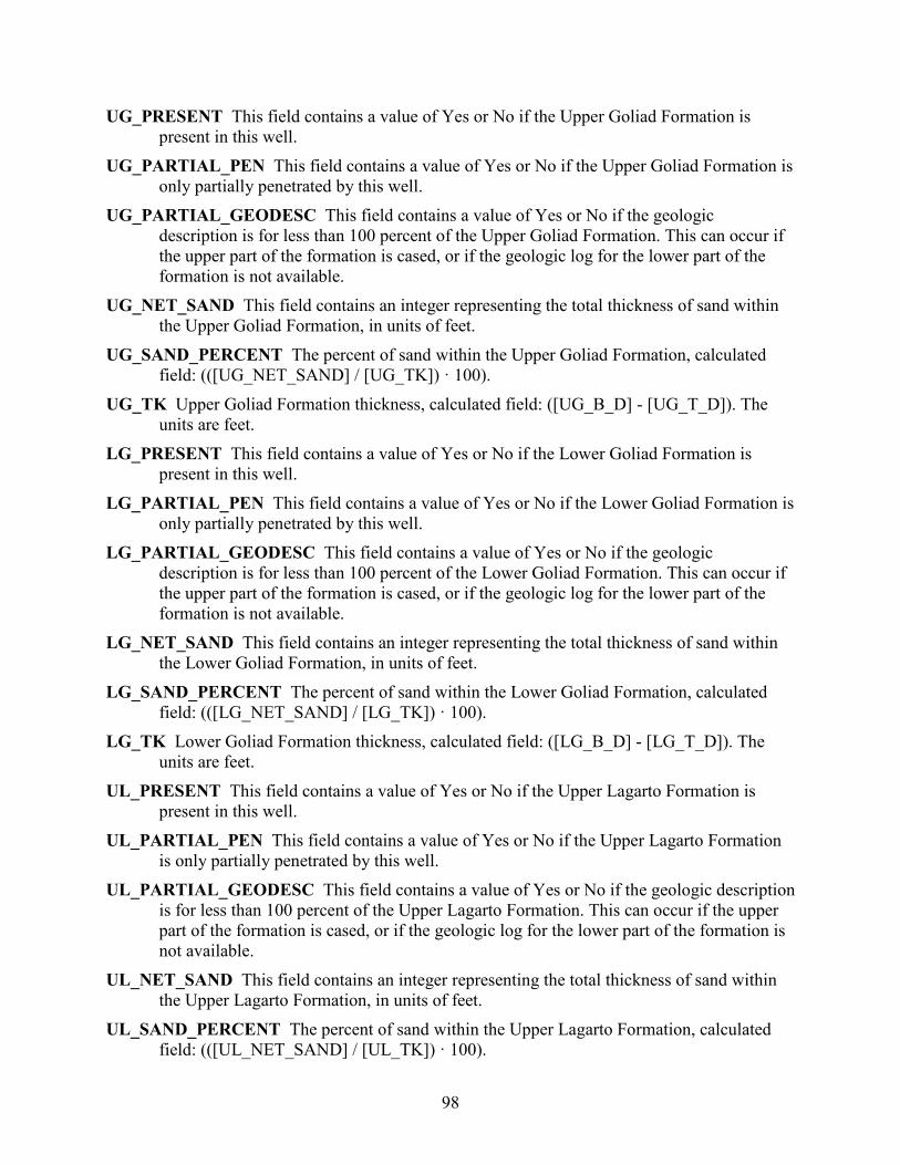
98
UG_PRESENT This field contains a value of Yes or No if the Upper Goliad Formation is present in this well.
UG_PARTIAL_PEN This field contains a value of Yes or No if the Upper Goliad Formation is only partially penetrated by this well.
UG_PARTIAL_GEODESC This field contains a value of Yes or No if the geologic description is for less than 100 percent of the Upper Goliad Formation. This can occur if the upper part of the formation is cased, or if the geologic log for the lower part of the formation is not available.
UG_NET_SAND This field contains an integer representing the total thickness of sand within the Upper Goliad Formation, in units of feet.
UG_SAND_PERCENT The percent of sand within the Upper Goliad Formation, calculated field: (([UG_NET_SAND] / [UG_TK]) · 100).
UG_TK Upper Goliad Formation thickness, calculated field: ([UG_B_D] - [UG_T_D]). The units are feet.
LG_PRESENT This field contains a value of Yes or No if the Lower Goliad Formation is present in this well.
LG_PARTIAL_PEN This field contains a value of Yes or No if the Lower Goliad Formation is only partially penetrated by this well.
LG_PARTIAL_GEODESC This field contains a value of Yes or No if the geologic description is for less than 100 percent of the Lower Goliad Formation. This can occur if the upper part of the formation is cased, or if the geologic log for the lower part of the formation is not available.
LG_NET_SAND This field contains an integer representing the total thickness of sand within the Lower Goliad Formation, in units of feet.
LG_SAND_PERCENT The percent of sand within the Lower Goliad Formation, calculated field: (([LG_NET_SAND] / [LG_TK]) · 100).
LG_TK Lower Goliad Formation thickness, calculated field: ([LG_B_D] - [LG_T_D]). The units are feet.
UL_PRESENT This field contains a value of Yes or No if the Upper Lagarto Formation is present in this well.
UL_PARTIAL_PEN This field contains a value of Yes or No if the Upper Lagarto Formation is only partially penetrated by this well.
UL_PARTIAL_GEODESC This field contains a value of Yes or No if the geologic description is for less than 100 percent of the Upper Lagarto Formation. This can occur if the upper part of the formation is cased, or if the geologic log for the lower part of the formation is not available.
UL_NET_SAND This field contains an integer representing the total thickness of sand within the Upper Lagarto Formation, in units of feet.
UL_SAND_PERCENT The percent of sand within the Upper Lagarto Formation, calculated field: (([UL_NET_SAND] / [UL_TK]) · 100).
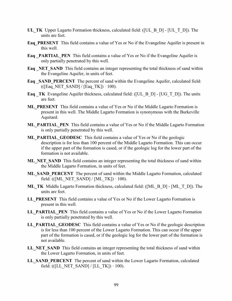
99
UL_TK Upper Lagarto Formation thickness, calculated field: ([UL_B_D] - [UL_T_D]). The units are feet.
Eaq_PRESENT This field contains a value of Yes or No if the Evangeline Aquifer is present in this well.
Eaq _PARTIAL_PEN This field contains a value of Yes or No if the Evangeline Aquifer is only partially penetrated by this well.
Eaq _NET_SAND This field contains an integer representing the total thickness of sand within the Evangeline Aquifer, in units of feet.
Eaq _SAND_PERCENT The percent of sand within the Evangeline Aquifer, calculated field: (([Eaq_NET_SAND] / [Eaq_TK]) · 100).
Eaq _TK Evangeline Aquifer thickness, calculated field: ([UL_B_D] - [UG_T_D]). The units are feet.
ML_PRESENT This field contains a value of Yes or No if the Middle Lagarto Formation is present in this well. The Middle Lagarto Formation is synonymous with the Burkeville Aquitard.
ML_PARTIAL_PEN This field contains a value of Yes or No if the Middle Lagarto Formation is only partially penetrated by this well.
ML_PARTIAL_GEODESC This field contains a value of Yes or No if the geologic description is for less than 100 percent of the Middle Lagarto Formation. This can occur if the upper part of the formation is cased, or if the geologic log for the lower part of the formation is not available.
ML_NET_SAND This field contains an integer representing the total thickness of sand within the Middle Lagarto Formation, in units of feet.
ML_SAND_PERCENT The percent of sand within the Middle Lagarto Formation, calculated field: (([ML_NET_SAND] / [ML_TK]) · 100).
ML_TK Middle Lagarto Formation thickness, calculated field: ([ML_B_D] - [ML_T_D]). The units are feet.
LL_PRESENT This field contains a value of Yes or No if the Lower Lagarto Formation is present in this well.
LL_PARTIAL_PEN This field contains a value of Yes or No if the Lower Lagarto Formation is only partially penetrated by this well.
LL_PARTIAL_GEODESC This field contains a value of Yes or No if the geologic description is for less than 100 percent of the Lower Lagarto Formation. This can occur if the upper part of the formation is cased, or if the geologic log for the lower part of the formation is not available.
LL_NET_SAND This field contains an integer representing the total thickness of sand within the Lower Lagarto Formation, in units of feet.
LL_SAND_PERCENT The percent of sand within the Lower Lagarto Formation, calculated field: (([LL_NET_SAND] / [LL_TK]) · 100).
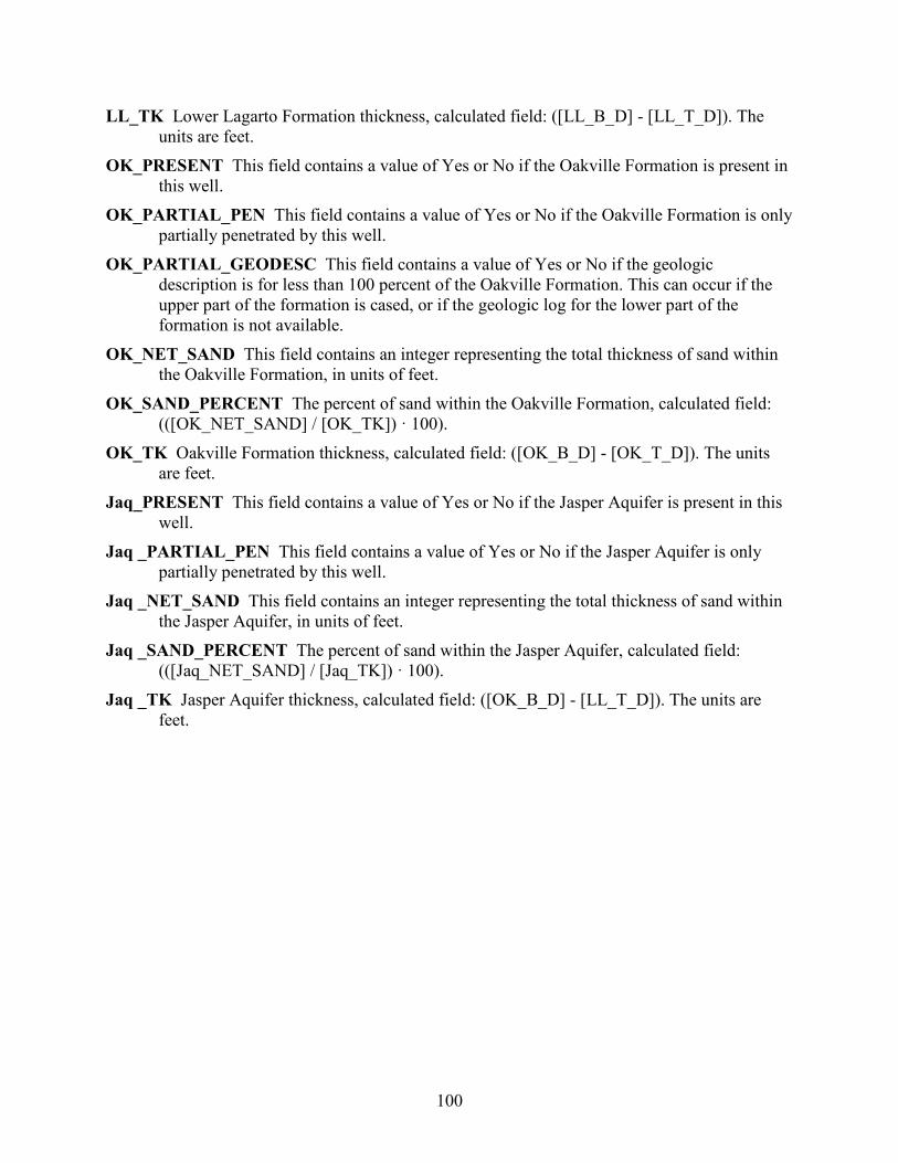
100
LL_TK Lower Lagarto Formation thickness, calculated field: ([LL_B_D] - [LL_T_D]). The units are feet.
OK_PRESENT This field contains a value of Yes or No if the Oakville Formation is present in this well.
OK_PARTIAL_PEN This field contains a value of Yes or No if the Oakville Formation is only partially penetrated by this well.
OK_PARTIAL_GEODESC This field contains a value of Yes or No if the geologic description is for less than 100 percent of the Oakville Formation. This can occur if the upper part of the formation is cased, or if the geologic log for the lower part of the formation is not available.
OK_NET_SAND This field contains an integer representing the total thickness of sand within the Oakville Formation, in units of feet.
OK_SAND_PERCENT The percent of sand within the Oakville Formation, calculated field: (([OK_NET_SAND] / [OK_TK]) · 100).
OK_TK Oakville Formation thickness, calculated field: ([OK_B_D] - [OK_T_D]). The units are feet.
Jaq_PRESENT This field contains a value of Yes or No if the Jasper Aquifer is present in this well.
Jaq _PARTIAL_PEN This field contains a value of Yes or No if the Jasper Aquifer is only partially penetrated by this well.
Jaq _NET_SAND This field contains an integer representing the total thickness of sand within the Jasper Aquifer, in units of feet.
Jaq _SAND_PERCENT The percent of sand within the Jasper Aquifer, calculated field: (([Jaq_NET_SAND] / [Jaq_TK]) · 100).
Jaq _TK Jasper Aquifer thickness, calculated field: ([OK_B_D] - [LL_T_D]). The units are feet.
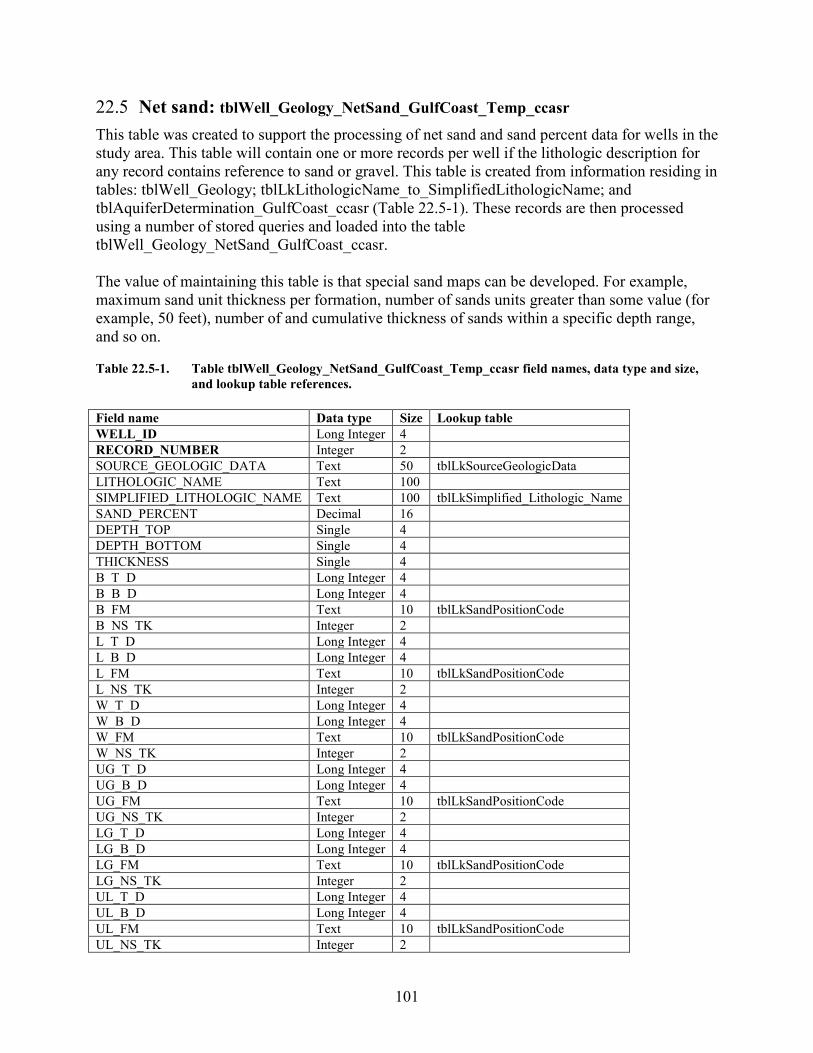
101
22.5 Net sand: tblWell_Geology_NetSand_GulfCoast_Temp_ccasr This table was created to support the processing of net sand and sand percent data for wells in the study area. This table will contain one or more records per well if the lithologic description for any record contains reference to sand or gravel. This table is created from information residing in tables: tblWell_Geology; tblLkLithologicName_to_SimplifiedLithologicName; and tblAquiferDetermination_GulfCoast_ccasr (Table 22.5-1). These records are then processed using a number of stored queries and loaded into the table tblWell_Geology_NetSand_GulfCoast_ccasr. The value of maintaining this table is that special sand maps can be developed. For example, maximum sand unit thickness per formation, number of sands units greater than some value (for example, 50 feet), number of and cumulative thickness of sands within a specific depth range, and so on. Table 22.5-1. Table tblWell_Geology_NetSand_GulfCoast_Temp_ccasr field names, data type and size,
and lookup table references. Field name Data type Size Lookup table WELL_ID Long Integer 4 RECORD_NUMBER Integer 2 SOURCE_GEOLOGIC_DATA Text 50 tblLkSourceGeologicData LITHOLOGIC_NAME Text 100 SIMPLIFIED_LITHOLOGIC_NAME Text 100 tblLkSimplified_Lithologic_Name SAND_PERCENT Decimal 16 DEPTH_TOP Single 4 DEPTH_BOTTOM Single 4 THICKNESS Single 4 B_T_D Long Integer 4 B_B_D Long Integer 4 B_FM Text 10 tblLkSandPositionCode B_NS_TK Integer 2 L_T_D Long Integer 4 L_B_D Long Integer 4 L_FM Text 10 tblLkSandPositionCode L_NS_TK Integer 2 W_T_D Long Integer 4 W_B_D Long Integer 4 W_FM Text 10 tblLkSandPositionCode W_NS_TK Integer 2 UG_T_D Long Integer 4 UG_B_D Long Integer 4 UG_FM Text 10 tblLkSandPositionCode UG_NS_TK Integer 2 LG_T_D Long Integer 4 LG_B_D Long Integer 4 LG_FM Text 10 tblLkSandPositionCode LG_NS_TK Integer 2 UL_T_D Long Integer 4 UL_B_D Long Integer 4 UL_FM Text 10 tblLkSandPositionCode UL_NS_TK Integer 2
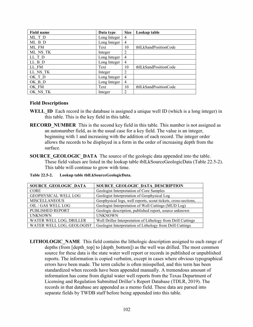
102
Field name Data type Size Lookup table ML_T_D Long Integer 4 ML_B_D Long Integer 4 ML_FM Text 10 tblLkSandPositionCode ML_NS_TK Integer 2 LL_T_D Long Integer 4 LL_B_D Long Integer 4 LL_FM Text 10 tblLkSandPositionCode LL_NS_TK Integer 2 OK_T_D Long Integer 4 OK_B_D Long Integer 4 OK_FM Text 10 tblLkSandPositionCode OK_NS_TK Integer 2 Field Descriptions WELL_ID Each record in the database is assigned a unique well ID (which is a long integer) in
this table. This is the key field in this table. RECORD_NUMBER This is the second key field in this table. This number is not assigned as
an autonumber field, as in the usual case for a key field. The value is an integer, beginning with 1 and increasing with the addition of each record. The integer order allows the records to be displayed in a form in the order of increasing depth from the surface.
SOURCE_GEOLOGIC_DATA The source of the geologic data appended into the table. These field values are listed in the lookup table tblLkSourceGeologicData (Table 22.5-2). This table will continue to grow with time.
Table 22.5-2. Lookup table tblLkSourceGeologicData. SOURCE_GEOLOGIC_DATA SOURCE_GEOLOGIC_DATA_DESCRIPTION CORE Geologist Interpretation of Core Samples GEOPHYSICAL WELL LOG Geologist Interpretation of Geophysical Log MISCELLANEOUS Geophysical logs, well reports, scout tickets, cross-sections, … OIL / GAS WELL LOG Geologist Interpretation of Well Cuttings (MUD Log) PUBLISHED REPORT Geologic description, published report, source unknown UNKNOWN UNKNOWN WATER WELL LOG, DRILLER Well Driller Interpretation of Lithology from Drill Cuttings WATER WELL LOG, GEOLOGIST Geologist Interpretation of Lithology from Drill Cuttings
LITHOLOGIC_NAME This field contains the lithologic description assigned to each range of depths (from [depth_top] to [depth_bottom]) as the well was drilled. The most common source for these data is the state water well report or records in published or unpublished reports. The information is copied verbatim, except in cases where obvious typographical errors have been made. The term caliche is often misspelled, and this term has been standardized when records have been appended manually. A tremendous amount of information has come from digital water well reports from the Texas Department of Licensing and Regulation Submitted Driller’s Report Database (TDLR, 2019). The records in that database are appended as a memo field. These data are parsed into separate fields by TWDB staff before being appended into this table.
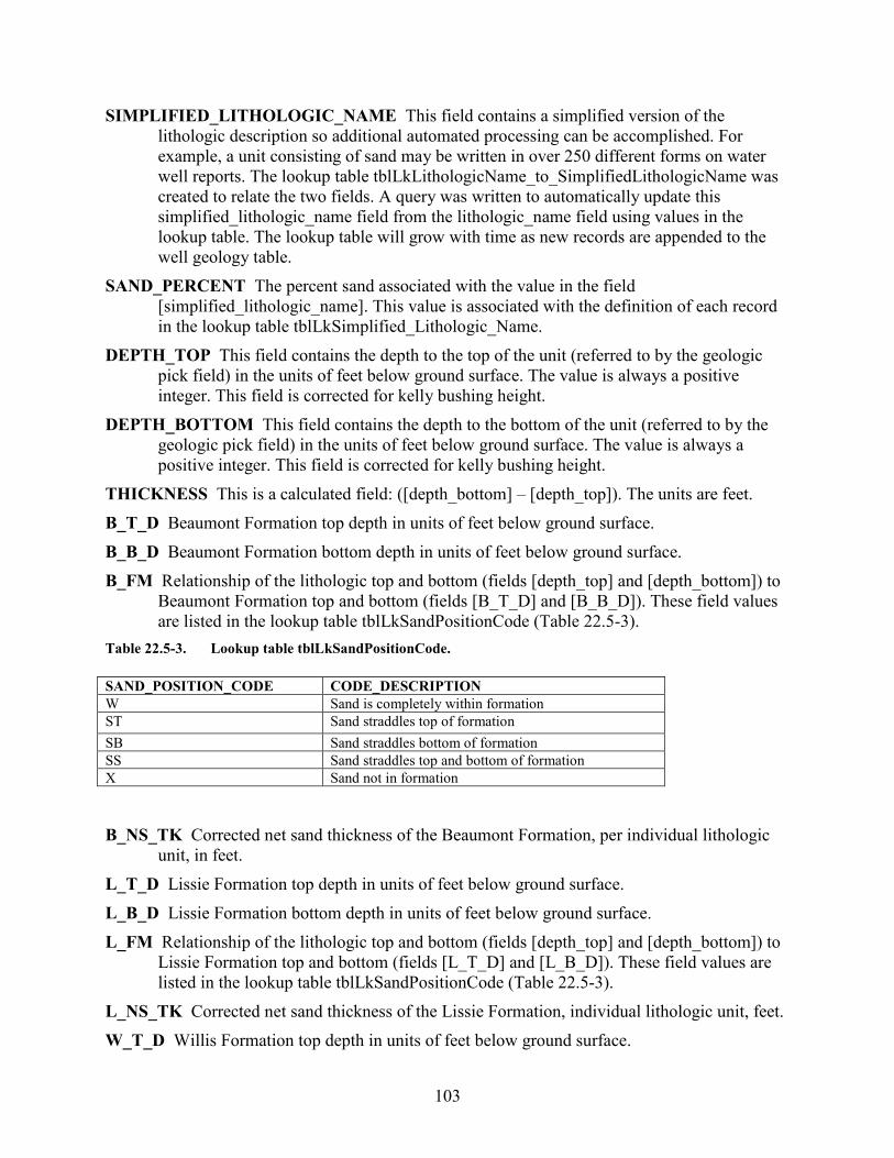
103
SIMPLIFIED_LITHOLOGIC_NAME This field contains a simplified version of the lithologic description so additional automated processing can be accomplished. For example, a unit consisting of sand may be written in over 250 different forms on water well reports. The lookup table tblLkLithologicName_to_SimplifiedLithologicName was created to relate the two fields. A query was written to automatically update this simplified_lithologic_name field from the lithologic_name field using values in the lookup table. The lookup table will grow with time as new records are appended to the well geology table.
SAND_PERCENT The percent sand associated with the value in the field [simplified_lithologic_name]. This value is associated with the definition of each record in the lookup table tblLkSimplified_Lithologic_Name.
DEPTH_TOP This field contains the depth to the top of the unit (referred to by the geologic pick field) in the units of feet below ground surface. The value is always a positive integer. This field is corrected for kelly bushing height.
DEPTH_BOTTOM This field contains the depth to the bottom of the unit (referred to by the geologic pick field) in the units of feet below ground surface. The value is always a positive integer. This field is corrected for kelly bushing height.
THICKNESS This is a calculated field: ([depth_bottom] – [depth_top]). The units are feet. B_T_D Beaumont Formation top depth in units of feet below ground surface. B_B_D Beaumont Formation bottom depth in units of feet below ground surface. B_FM Relationship of the lithologic top and bottom (fields [depth_top] and [depth_bottom]) to
Beaumont Formation top and bottom (fields [B_T_D] and [B_B_D]). These field values are listed in the lookup table tblLkSandPositionCode (Table 22.5-3).
Table 22.5-3. Lookup table tblLkSandPositionCode. SAND_POSITION_CODE CODE_DESCRIPTION W Sand is completely within formation ST Sand straddles top of formation SB Sand straddles bottom of formation SS Sand straddles top and bottom of formation X Sand not in formation
B_NS_TK Corrected net sand thickness of the Beaumont Formation, per individual lithologic
unit, in feet. L_T_D Lissie Formation top depth in units of feet below ground surface. L_B_D Lissie Formation bottom depth in units of feet below ground surface. L_FM Relationship of the lithologic top and bottom (fields [depth_top] and [depth_bottom]) to
Lissie Formation top and bottom (fields [L_T_D] and [L_B_D]). These field values are listed in the lookup table tblLkSandPositionCode (Table 22.5-3).
L_NS_TK Corrected net sand thickness of the Lissie Formation, individual lithologic unit, feet. W_T_D Willis Formation top depth in units of feet below ground surface.
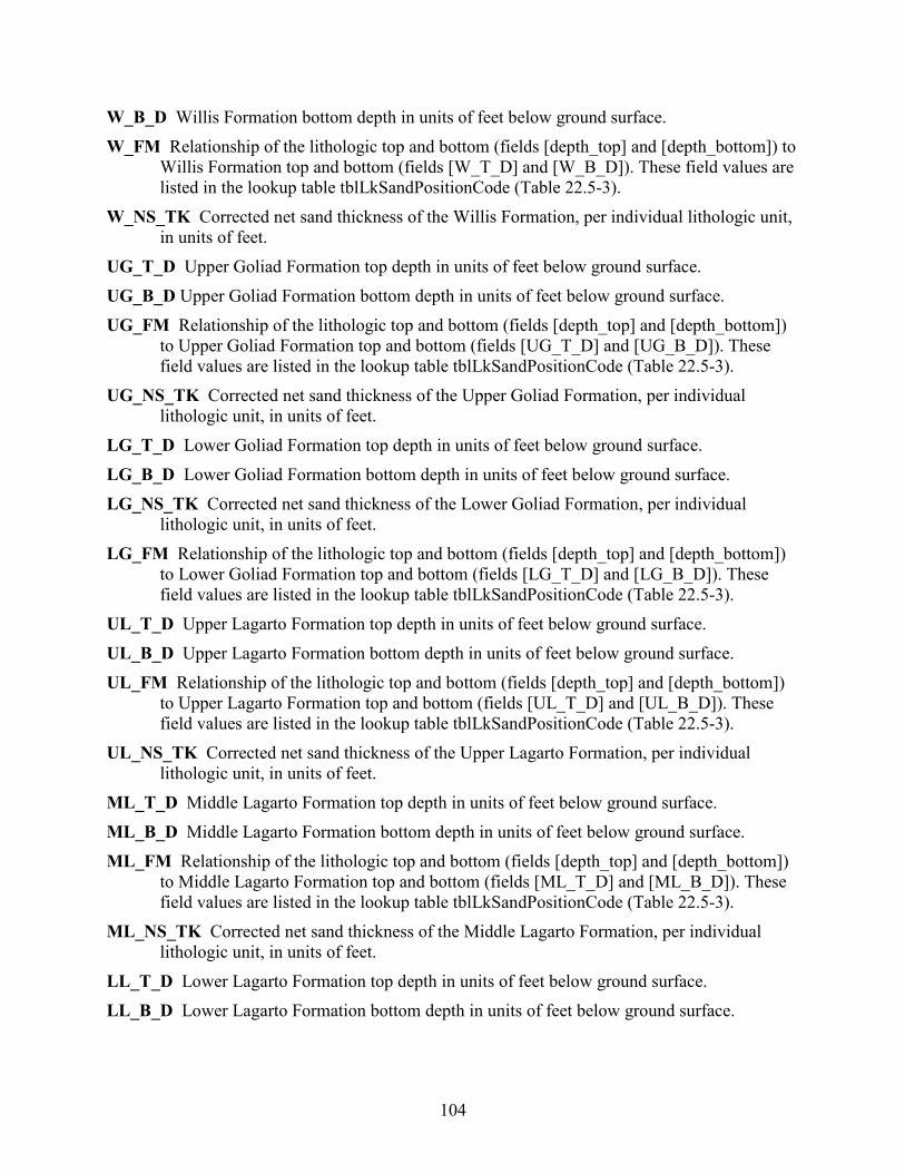
104
W_B_D Willis Formation bottom depth in units of feet below ground surface. W_FM Relationship of the lithologic top and bottom (fields [depth_top] and [depth_bottom]) to
Willis Formation top and bottom (fields [W_T_D] and [W_B_D]). These field values are listed in the lookup table tblLkSandPositionCode (Table 22.5-3).
W_NS_TK Corrected net sand thickness of the Willis Formation, per individual lithologic unit, in units of feet.
UG_T_D Upper Goliad Formation top depth in units of feet below ground surface. UG_B_D Upper Goliad Formation bottom depth in units of feet below ground surface. UG_FM Relationship of the lithologic top and bottom (fields [depth_top] and [depth_bottom])
to Upper Goliad Formation top and bottom (fields [UG_T_D] and [UG_B_D]). These field values are listed in the lookup table tblLkSandPositionCode (Table 22.5-3).
UG_NS_TK Corrected net sand thickness of the Upper Goliad Formation, per individual lithologic unit, in units of feet.
LG_T_D Lower Goliad Formation top depth in units of feet below ground surface. LG_B_D Lower Goliad Formation bottom depth in units of feet below ground surface. LG_NS_TK Corrected net sand thickness of the Lower Goliad Formation, per individual
lithologic unit, in units of feet. LG_FM Relationship of the lithologic top and bottom (fields [depth_top] and [depth_bottom])
to Lower Goliad Formation top and bottom (fields [LG_T_D] and [LG_B_D]). These field values are listed in the lookup table tblLkSandPositionCode (Table 22.5-3).
UL_T_D Upper Lagarto Formation top depth in units of feet below ground surface. UL_B_D Upper Lagarto Formation bottom depth in units of feet below ground surface. UL_FM Relationship of the lithologic top and bottom (fields [depth_top] and [depth_bottom])
to Upper Lagarto Formation top and bottom (fields [UL_T_D] and [UL_B_D]). These field values are listed in the lookup table tblLkSandPositionCode (Table 22.5-3).
UL_NS_TK Corrected net sand thickness of the Upper Lagarto Formation, per individual lithologic unit, in units of feet.
ML_T_D Middle Lagarto Formation top depth in units of feet below ground surface. ML_B_D Middle Lagarto Formation bottom depth in units of feet below ground surface. ML_FM Relationship of the lithologic top and bottom (fields [depth_top] and [depth_bottom])
to Middle Lagarto Formation top and bottom (fields [ML_T_D] and [ML_B_D]). These field values are listed in the lookup table tblLkSandPositionCode (Table 22.5-3).
ML_NS_TK Corrected net sand thickness of the Middle Lagarto Formation, per individual lithologic unit, in units of feet.
LL_T_D Lower Lagarto Formation top depth in units of feet below ground surface. LL_B_D Lower Lagarto Formation bottom depth in units of feet below ground surface.

105
LL_FM Relationship of the lithologic top and bottom (fields [depth_top] and [depth_bottom]) to Lower Lagarto Formation top and bottom (fields [LL_T_D] and [LL_B_D]). These field values are listed in the lookup table tblLkSandPositionCode (Table 22.5-3).
LL_NS_TK Corrected net sand thickness of the Lower Lagarto Formation, per individual lithologic unit, in units of feet.
OK_T_D Oakville Formation top depth in units of feet below ground surface. OK_B_D Oakville Formation bottom depth in units of feet below ground surface. OK_FM Relationship of the lithologic top and bottom (fields [depth_top] and [depth_bottom])
to Oakville Formation top and bottom (fields [OK_T_D] and [OK_B_D]). These field values are listed in the lookup table tblLkSandPositionCode (Table 22.5-3).
OK_NS_TK Corrected net sand thickness of the Oakville Formation, per individual lithologic unit, in units of feet.

106
23. Appendix C: Lower Rio Grande Valley Gulf Coast Aquifer BRACS Study
The tables in this appendix were developed for the following Texas Water Development Board BRACS study: Meyer, J.E., Croskrey, A.D., Wise, M.R., and Kalaswad, S., 2014, Brackish Groundwater in the
Gulf Coast Aquifer, Lower Rio Grande Valley, Texas: Texas Water Development Board Report 383, 169 p.
23.1 Aquifer determination: tblAquiferDetermination_GulfCoast This table contains information on which aquifer(s) may be used or penetrated by a well in the Gulf Coast Aquifer in the study area (Table 23.1-1). Although aquifer codes have been assigned to wells in the Groundwater Database (TWDB, 2019b), it was determined that a systematic assessment of every well in the study area using the 3-dimensional formation top and bottom surfaces with available well screen and well depth data would provide a more accurate and uniform aquifer assignment. Using the new aquifer codes, wells with water quality data could be compared to wells using the same aquifer. Every well within the limits of the study area that is in the BRACS Database (TWDB, 2019a) and the Groundwater Database was appended to a holding table. This information was imported and geo-referenced in a geographic information system (GIS). The top and bottom of each formation of interest was determined at each well location, and the values were written to the holding table. For this study, the formations within the Gulf Coast Aquifer, in descending order, include Beaumont, Lissie, Willis, Upper Goliad, Lower Goliad, Upper Lagarto, Middle Lagarto, Lower Lagarto, and the Oakville. Values for the shallowest and deepest screen depths, well depths, and total depth of hole were obtained from TWDB BRACS and Groundwater Database tables. A series of stored queries in Microsoft® Access® was used to determine if a well screen intersected a particular formation. A well may be screened in one or more aquifers. If well screen information was not available, well depth or total depth of hole were used to determine potential aquifers that were penetrated. A value of -99999 is written to elevation and depth fields if data are unknown. Table 23.1-1. Table tblAquiferDetermination_GulfCoast field names, data type and size, and lookup table
references. Field name Data type Size Lookup table WELL_ID Long Integer 4 STATE_WELL_NUMBER Long Integer 4 REGION Long Integer 4 AQUIFER_CODE Text 8 tblLkAquifer AQUIFER_NEW Text 50 tblLkBRACS_Aquifer_AD O_G_WELL_AQ_PENETRATED Text 50 AQ_REASON Text 10 AQ_DECISION Text 100 tblLkAq_Decision DEPTH_WELL Long Integer 4 DEPTH_TOTAL Long Integer 4 SCREEN_TOP Long Integer 4 SCREEN_BOTTOM Long Integer 4
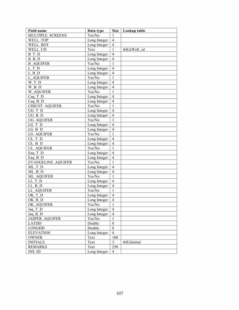
107
Field name Data type Size Lookup table MULTIPLE_SCREENS Yes/No 1 WELL_TOP Long Integer 4 WELL_BOT Long Integer 4 WELL_CD Text 1 tblLkWell_cd B_T_D Long Integer 4 B_B_D Long Integer 4 B_AQUIFER Yes/No 1 L_T_D Long Integer 4 L_B_D Long Integer 4 L_AQUIFER Yes/No 1 W_T_D Long Integer 4 W_B_D Long Integer 4 W_AQUIFER Yes/No 1 Caq_T_D Long Integer 4 Caq_B_D Long Integer 4 CHICOT_AQUIFER Yes/No 1 UG_T_D Long Integer 4 UG_B_D Long Integer 4 UG_AQUIFER Yes/No 1 LG_T_D Long Integer 4 LG_B_D Long Integer 4 LG_AQUIFER Yes/No 1 UL_T_D Long Integer 4 UL_B_D Long Integer 4 UL_AQUIFER Yes/No 1 Eaq_T_D Long Integer 4 Eaq_B_D Long Integer 4 EVANGELINE_AQUIFER Yes/No 1 ML_T_D Long Integer 4 ML_B_D Long Integer 4 ML_AQUIFER Yes/No 1 LL_T_D Long Integer 4 LL_B_D Long Integer 4 LL_AQUIFER Yes/No 1 OK_T_D Long Integer 4 OK_B_D Long Integer 4 OK_AQUIFER Yes/No 1 Jaq_T_D Long Integer 4 Jaq_B_D Long Integer 4 JASPER_AQUIFER Yes/No 1 LATDD Double 8 LONGDD Double 8 ELEVATION Long Integer 4 OWNER Text 100 INITIALS Text 3 tblLkInitial REMARKS Text 250 INS_ID Long Integer 4
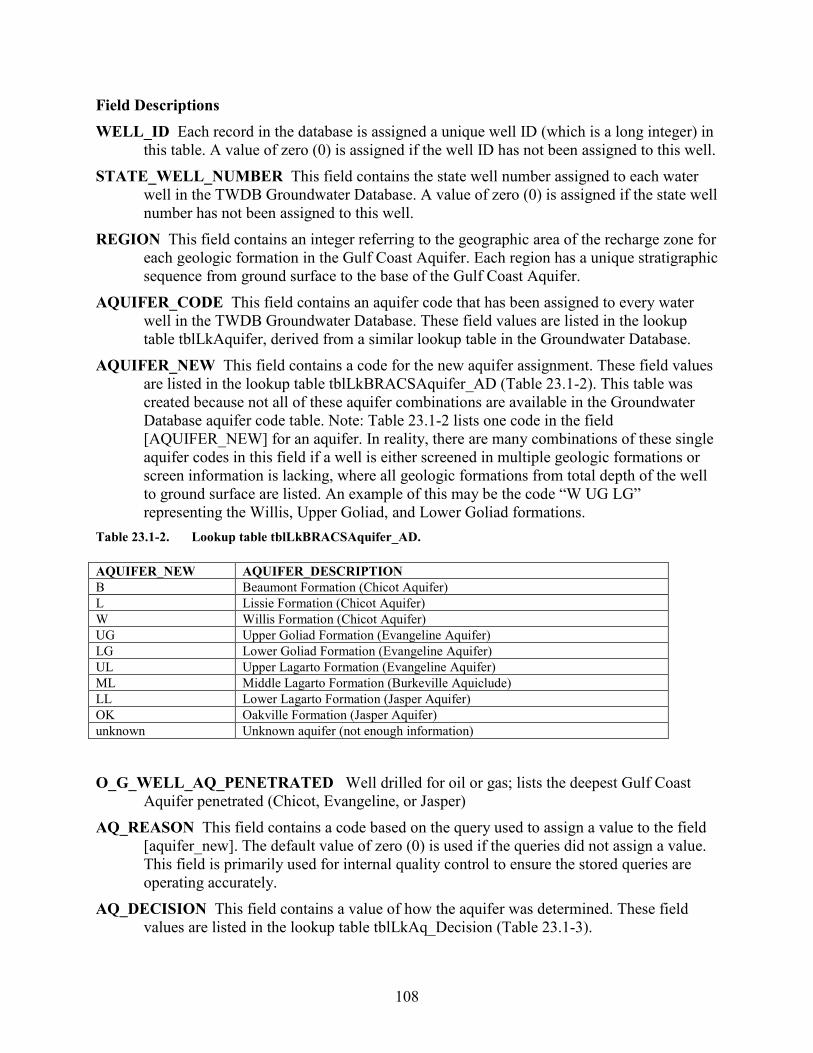
108
Field Descriptions WELL_ID Each record in the database is assigned a unique well ID (which is a long integer) in
this table. A value of zero (0) is assigned if the well ID has not been assigned to this well. STATE_WELL_NUMBER This field contains the state well number assigned to each water
well in the TWDB Groundwater Database. A value of zero (0) is assigned if the state well number has not been assigned to this well.
REGION This field contains an integer referring to the geographic area of the recharge zone for each geologic formation in the Gulf Coast Aquifer. Each region has a unique stratigraphic sequence from ground surface to the base of the Gulf Coast Aquifer.
AQUIFER_CODE This field contains an aquifer code that has been assigned to every water well in the TWDB Groundwater Database. These field values are listed in the lookup table tblLkAquifer, derived from a similar lookup table in the Groundwater Database.
AQUIFER_NEW This field contains a code for the new aquifer assignment. These field values are listed in the lookup table tblLkBRACSAquifer_AD (Table 23.1-2). This table was created because not all of these aquifer combinations are available in the Groundwater Database aquifer code table. Note: Table 23.1-2 lists one code in the field [AQUIFER_NEW] for an aquifer. In reality, there are many combinations of these single aquifer codes in this field if a well is either screened in multiple geologic formations or screen information is lacking, where all geologic formations from total depth of the well to ground surface are listed. An example of this may be the code “W UG LG” representing the Willis, Upper Goliad, and Lower Goliad formations.
Table 23.1-2. Lookup table tblLkBRACSAquifer_AD. AQUIFER_NEW AQUIFER_DESCRIPTION B Beaumont Formation (Chicot Aquifer) L Lissie Formation (Chicot Aquifer) W Willis Formation (Chicot Aquifer) UG Upper Goliad Formation (Evangeline Aquifer) LG Lower Goliad Formation (Evangeline Aquifer) UL Upper Lagarto Formation (Evangeline Aquifer) ML Middle Lagarto Formation (Burkeville Aquiclude) LL Lower Lagarto Formation (Jasper Aquifer) OK Oakville Formation (Jasper Aquifer) unknown Unknown aquifer (not enough information)
O_G_WELL_AQ_PENETRATED Well drilled for oil or gas; lists the deepest Gulf Coast
Aquifer penetrated (Chicot, Evangeline, or Jasper) AQ_REASON This field contains a code based on the query used to assign a value to the field
[aquifer_new]. The default value of zero (0) is used if the queries did not assign a value. This field is primarily used for internal quality control to ensure the stored queries are operating accurately.
AQ_DECISION This field contains a value of how the aquifer was determined. These field values are listed in the lookup table tblLkAq_Decision (Table 23.1-3).
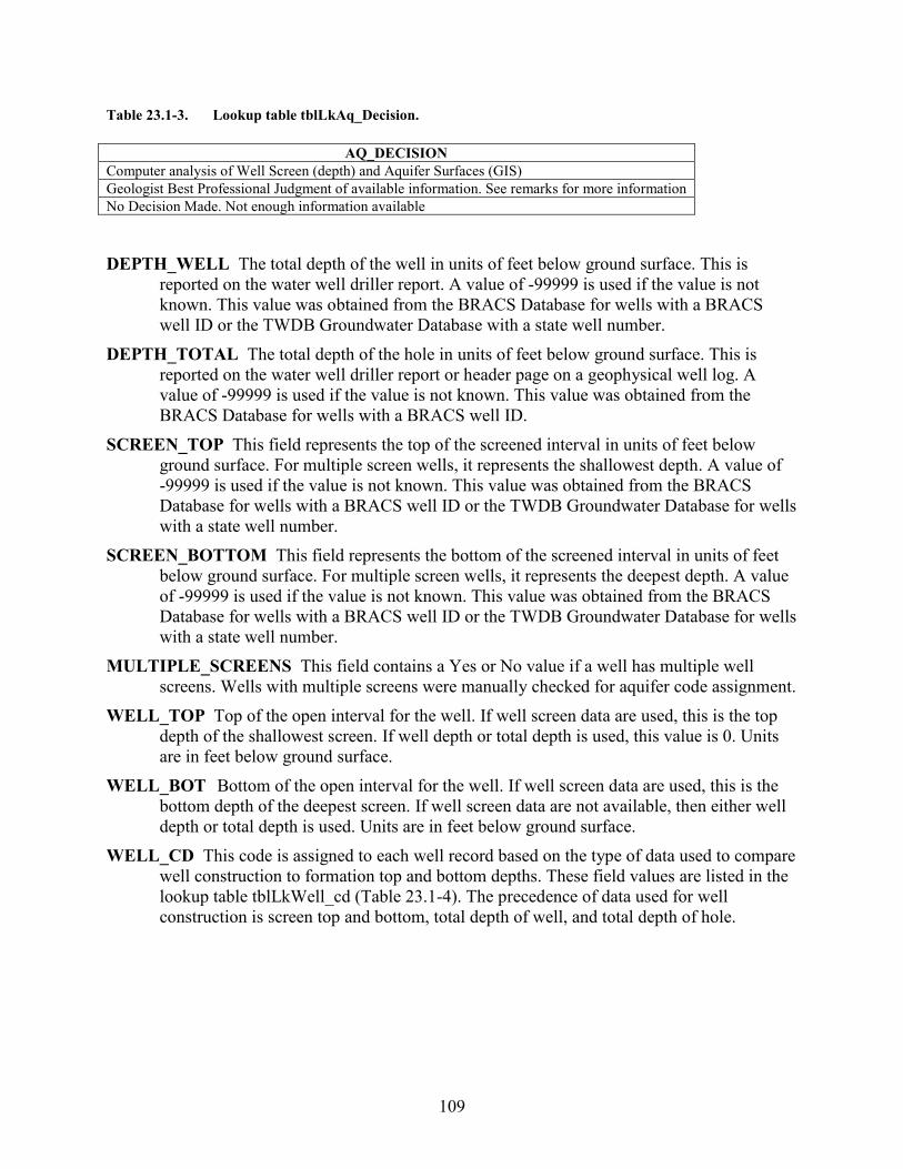
109
Table 23.1-3. Lookup table tblLkAq_Decision.
AQ_DECISION Computer analysis of Well Screen (depth) and Aquifer Surfaces (GIS) Geologist Best Professional Judgment of available information. See remarks for more information No Decision Made. Not enough information available
DEPTH_WELL The total depth of the well in units of feet below ground surface. This is
reported on the water well driller report. A value of -99999 is used if the value is not known. This value was obtained from the BRACS Database for wells with a BRACS well ID or the TWDB Groundwater Database with a state well number.
DEPTH_TOTAL The total depth of the hole in units of feet below ground surface. This is reported on the water well driller report or header page on a geophysical well log. A value of -99999 is used if the value is not known. This value was obtained from the BRACS Database for wells with a BRACS well ID.
SCREEN_TOP This field represents the top of the screened interval in units of feet below ground surface. For multiple screen wells, it represents the shallowest depth. A value of -99999 is used if the value is not known. This value was obtained from the BRACS Database for wells with a BRACS well ID or the TWDB Groundwater Database for wells with a state well number.
SCREEN_BOTTOM This field represents the bottom of the screened interval in units of feet below ground surface. For multiple screen wells, it represents the deepest depth. A value of -99999 is used if the value is not known. This value was obtained from the BRACS Database for wells with a BRACS well ID or the TWDB Groundwater Database for wells with a state well number.
MULTIPLE_SCREENS This field contains a Yes or No value if a well has multiple well screens. Wells with multiple screens were manually checked for aquifer code assignment.
WELL_TOP Top of the open interval for the well. If well screen data are used, this is the top depth of the shallowest screen. If well depth or total depth is used, this value is 0. Units are in feet below ground surface.
WELL_BOT Bottom of the open interval for the well. If well screen data are used, this is the bottom depth of the deepest screen. If well screen data are not available, then either well depth or total depth is used. Units are in feet below ground surface.
WELL_CD This code is assigned to each well record based on the type of data used to compare well construction to formation top and bottom depths. These field values are listed in the lookup table tblLkWell_cd (Table 23.1-4). The precedence of data used for well construction is screen top and bottom, total depth of well, and total depth of hole.
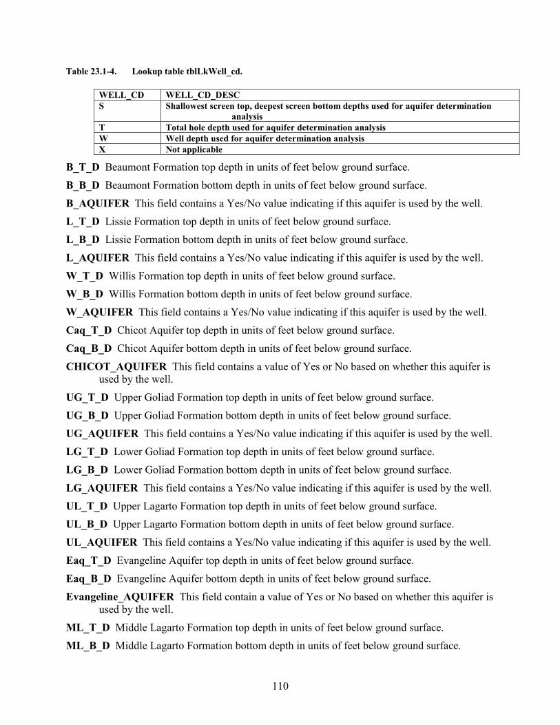
110
Table 23.1-4. Lookup table tblLkWell_cd.
WELL_CD WELL_CD_DESC S Shallowest screen top, deepest screen bottom depths used for aquifer determination
analysis T Total hole depth used for aquifer determination analysis W Well depth used for aquifer determination analysis X Not applicable
B_T_D Beaumont Formation top depth in units of feet below ground surface. B_B_D Beaumont Formation bottom depth in units of feet below ground surface. B_AQUIFER This field contains a Yes/No value indicating if this aquifer is used by the well. L_T_D Lissie Formation top depth in units of feet below ground surface. L_B_D Lissie Formation bottom depth in units of feet below ground surface. L_AQUIFER This field contains a Yes/No value indicating if this aquifer is used by the well. W_T_D Willis Formation top depth in units of feet below ground surface. W_B_D Willis Formation bottom depth in units of feet below ground surface. W_AQUIFER This field contains a Yes/No value indicating if this aquifer is used by the well. Caq_T_D Chicot Aquifer top depth in units of feet below ground surface. Caq_B_D Chicot Aquifer bottom depth in units of feet below ground surface. CHICOT_AQUIFER This field contains a value of Yes or No based on whether this aquifer is
used by the well. UG_T_D Upper Goliad Formation top depth in units of feet below ground surface. UG_B_D Upper Goliad Formation bottom depth in units of feet below ground surface. UG_AQUIFER This field contains a Yes/No value indicating if this aquifer is used by the well. LG_T_D Lower Goliad Formation top depth in units of feet below ground surface. LG_B_D Lower Goliad Formation bottom depth in units of feet below ground surface. LG_AQUIFER This field contains a Yes/No value indicating if this aquifer is used by the well. UL_T_D Upper Lagarto Formation top depth in units of feet below ground surface. UL_B_D Upper Lagarto Formation bottom depth in units of feet below ground surface. UL_AQUIFER This field contains a Yes/No value indicating if this aquifer is used by the well. Eaq_T_D Evangeline Aquifer top depth in units of feet below ground surface. Eaq_B_D Evangeline Aquifer bottom depth in units of feet below ground surface. Evangeline_AQUIFER This field contain a value of Yes or No based on whether this aquifer is
used by the well. ML_T_D Middle Lagarto Formation top depth in units of feet below ground surface. ML_B_D Middle Lagarto Formation bottom depth in units of feet below ground surface.
111
ML_AQUIFER This field contains a Yes/No value indicating if this aquifer is used by the well. LL_T_D Lower Lagarto Formation top depth in units of feet below ground surface. LL_B_D Lower Lagarto Formation bottom depth in units of feet below ground surface. LL_AQUIFER This field contains a Yes/No value indicating if this aquifer is used by the well. OK_T_D Oakville Formation top depth in units of feet below ground surface. OK_B_D Oakville Formation bottom depth in units of feet below ground surface. OK_AQUIFER This field contains a Yes/No value indicating if this aquifer is used by the well. Jaq_T_D Jasper Aquifer top depth in units of feet below ground surface. Jaq_B_D Jasper Aquifer bottom depth in units of feet below ground surface. Jasper_AQUIFER This field contains a value of Yes or No based on whether this aquifer is
used by the well. LATDD Latitude of the well site in units of decimal degrees. Latitude is a positive value,
referring to a site north of the earth’s equator. Latitude and longitude coordinates are obtained from multiple sources. Latitude is obtained based on a North American Datum of 1983. This value was obtained from the well location table.
LONGDD Longitude of the well site in units of decimal degrees. Longitude is a negative value, referring to a site west of the Prime Meridian in Greenwich, United Kingdom. Latitude and longitude coordinates are obtained from multiple sources. Longitude is based on a North American Datum of 1983. This value was obtained from the well location table.
ELEVATION The elevation of the well site in units of feet above mean sea level. The elevation is determined using spatial analysis in a geographic information system by comparing the well site with the 30-meter digital elevation model for Texas. This value was obtained from the well location table. A value of -99999 is used if the value is not known.
OWNER The name of the well owner. This value was obtained from the well location table. INITIALS Initials of person who last edited the record. REMARKS General remarks associated with the well record. INS_ID This field is a unique id used for loading geologic formation top and bottom depths
from GIS.
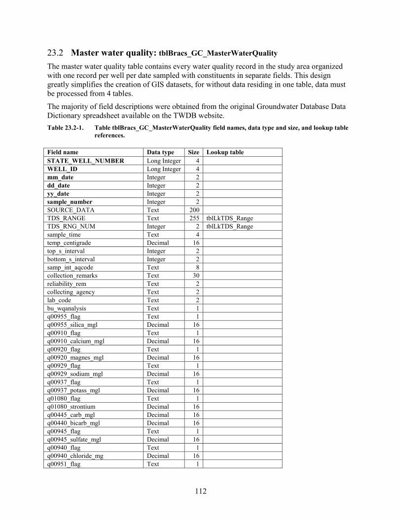
112
23.2 Master water quality: tblBracs_GC_MasterWaterQuality The master water quality table contains every water quality record in the study area organized with one record per well per date sampled with constituents in separate fields. This design greatly simplifies the creation of GIS datasets, for without data residing in one table, data must be processed from 4 tables. The majority of field descriptions were obtained from the original Groundwater Database Data Dictionary spreadsheet available on the TWDB website. Table 23.2-1. Table tblBracs_GC_MasterWaterQuality field names, data type and size, and lookup table
references. Field name Data type Size Lookup table STATE_WELL_NUMBER Long Integer 4
WELL_ID Long Integer 4
mm_date Integer 2
dd_date Integer 2
yy_date Integer 2
sample_number Integer 2
SOURCE_DATA Text 200
TDS_RANGE Text 255 tblLkTDS_Range TDS_RNG_NUM Integer 2 tblLkTDS_Range sample_time Text 4
temp_centigrade Decimal 16
top_s_interval Integer 2
bottom_s_interval Integer 2
samp_int_aqcode Text 8
collection_remarks Text 30
reliability_rem Text 2
collecting_agency Text 2
lab_code Text 2
bu_wqanalysis Text 1
q00955_flag Text 1
q00955_silica_mgl Decimal 16
q00910_flag Text 1
q00910_calcium_mgl Decimal 16
q00920_flag Text 1
q00920_magnes_mgl Decimal 16
q00929_flag Text 1
q00929_sodium_mgl Decimal 16
q00937_flag Text 1
q00937_potass_mgl Decimal 16
q01080_flag Text 1
q01080_strontium Decimal 16
q00445_carb_mgl Decimal 16
q00440_bicarb_mgl Decimal 16
q00945_flag Text 1
q00945_sulfate_mgl Decimal 16
q00940_flag Text 1
q00940_chloride_mg Decimal 16
q00951_flag Text 1
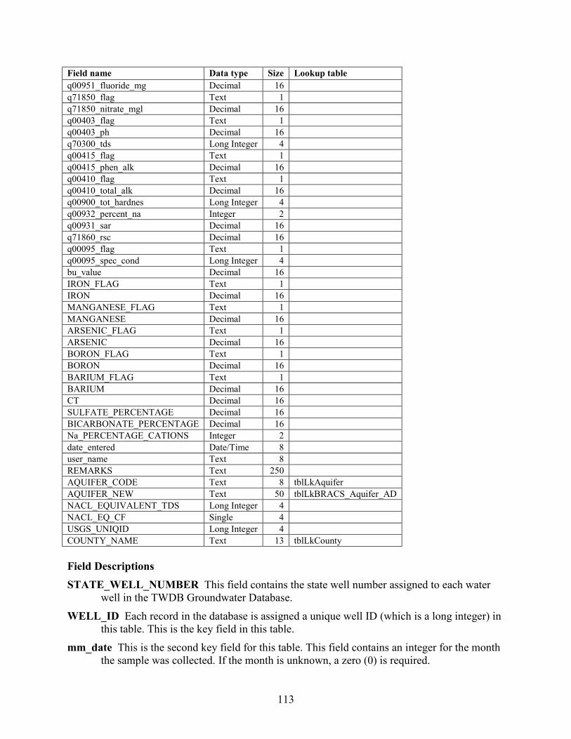
113
Field name Data type Size Lookup table q00951_fluoride_mg Decimal 16
q71850_flag Text 1
q71850_nitrate_mgl Decimal 16
q00403_flag Text 1
q00403_ph Decimal 16
q70300_tds Long Integer 4
q00415_flag Text 1
q00415_phen_alk Decimal 16
q00410_flag Text 1
q00410_total_alk Decimal 16
q00900_tot_hardnes Long Integer 4
q00932_percent_na Integer 2
q00931_sar Decimal 16
q71860_rsc Decimal 16
q00095_flag Text 1
q00095_spec_cond Long Integer 4
bu_value Decimal 16
IRON_FLAG Text 1
IRON Decimal 16
MANGANESE_FLAG Text 1
MANGANESE Decimal 16
ARSENIC_FLAG Text 1 ARSENIC Decimal 16 BORON_FLAG Text 1 BORON Decimal 16 BARIUM_FLAG Text 1 BARIUM Decimal 16 CT Decimal 16 SULFATE_PERCENTAGE Decimal 16
BICARBONATE_PERCENTAGE Decimal 16
Na_PERCENTAGE_CATIONS Integer 2
date_entered Date/Time 8
user_name Text 8
REMARKS Text 250
AQUIFER_CODE Text 8 tblLkAquifer AQUIFER_NEW Text 50 tblLkBRACS_Aquifer_AD NACL_EQUIVALENT_TDS Long Integer 4 NACL_EQ_CF Single 4 USGS_UNIQID Long Integer 4 COUNTY_NAME Text 13 tblLkCounty Field Descriptions STATE_WELL_NUMBER This field contains the state well number assigned to each water
well in the TWDB Groundwater Database. WELL_ID Each record in the database is assigned a unique well ID (which is a long integer) in
this table. This is the key field in this table. mm_date This is the second key field for this table. This field contains an integer for the month
the sample was collected. If the month is unknown, a zero (0) is required.
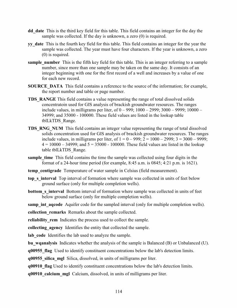
114
dd_date This is the third key field for this table. This field contains an integer for the day the sample was collected. If the day is unknown, a zero (0) is required.
yy_date This is the fourth key field for this table. This field contains an integer for the year the sample was collected. The year must have four characters. If the year is unknown, a zero (0) is required.
sample_number This is the fifth key field for this table. This is an integer referring to a sample number, since more than one sample may be taken on the same day. It consists of an integer beginning with one for the first record of a well and increases by a value of one for each new record.
SOURCE_DATA This field contains a reference to the source of the information; for example, the report number and table or page number.
TDS_RANGE This field contains a value representing the range of total dissolved solids concentratoin used for GIS analysis of brackish groundwater resources. The ranges include values, in milligrams per liter, of 0 – 999; 1000 – 2999; 3000 – 9999; 10000 – 34999; and 35000 - 100000. These field values are listed in the lookup table tblLkTDS_Range.
TDS_RNG_NUM This field contains an integer value representing the range of total dissolved solids concentration used for GIS analysis of brackish groundwater resources. The ranges include values, in milligrams per liter, of 1 = 0 – 999; 2 = 1000 – 2999; 3 = 3000 – 9999; 4 = 10000 – 34999; and 5 = 35000 - 100000. These field values are listed in the lookup table tblLkTDS_Range.
sample_time This field contains the time the sample was collected using four digits in the format of a 24-hour time period (for example, 8:45 a.m. is 0845; 4:21 p.m. is 1621).
temp_centigrade Temperature of water sample in Celsius (field measurement). top_s_interval Top interval of formation where sample was collected in units of feet below
ground surface (only for multiple completion wells). bottom_s_interval Bottom interval of formation where sample was collected in units of feet
below ground surface (only for multiple completion wells). samp_int_aqcode Aquifer code for the sampled interval (only for multiple completion wells). collection_remarks Remarks about the sample collected. reliability_rem Indicates the process used to collect the sample. collecting_agency Identifies the entity that collected the sample. lab_code Identifies the lab used to analyze the sample. bu_wqanalysis Indicates whether the analysis of the sample is Balanced (B) or Unbalanced (U). q00955_flag Used to identify constituent concentrations below the lab's detection limits. q00955_silica_mgl Silica, dissolved, in units of milligrams per liter. q00910_flag Used to identify constituent concentrations below the lab's detection limits. q00910_calcium_mgl Calcium, dissolved, in units of milligrams per liter.
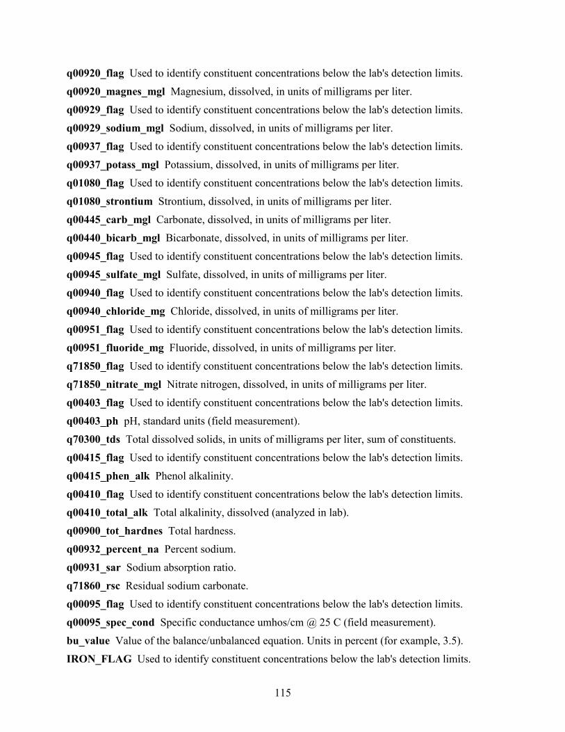
115
q00920_flag Used to identify constituent concentrations below the lab's detection limits. q00920_magnes_mgl Magnesium, dissolved, in units of milligrams per liter. q00929_flag Used to identify constituent concentrations below the lab's detection limits. q00929_sodium_mgl Sodium, dissolved, in units of milligrams per liter. q00937_flag Used to identify constituent concentrations below the lab's detection limits. q00937_potass_mgl Potassium, dissolved, in units of milligrams per liter. q01080_flag Used to identify constituent concentrations below the lab's detection limits. q01080_strontium Strontium, dissolved, in units of milligrams per liter. q00445_carb_mgl Carbonate, dissolved, in units of milligrams per liter. q00440_bicarb_mgl Bicarbonate, dissolved, in units of milligrams per liter. q00945_flag Used to identify constituent concentrations below the lab's detection limits. q00945_sulfate_mgl Sulfate, dissolved, in units of milligrams per liter. q00940_flag Used to identify constituent concentrations below the lab's detection limits. q00940_chloride_mg Chloride, dissolved, in units of milligrams per liter. q00951_flag Used to identify constituent concentrations below the lab's detection limits. q00951_fluoride_mg Fluoride, dissolved, in units of milligrams per liter. q71850_flag Used to identify constituent concentrations below the lab's detection limits. q71850_nitrate_mgl Nitrate nitrogen, dissolved, in units of milligrams per liter. q00403_flag Used to identify constituent concentrations below the lab's detection limits. q00403_ph pH, standard units (field measurement). q70300_tds Total dissolved solids, in units of milligrams per liter, sum of constituents. q00415_flag Used to identify constituent concentrations below the lab's detection limits. q00415_phen_alk Phenol alkalinity. q00410_flag Used to identify constituent concentrations below the lab's detection limits. q00410_total_alk Total alkalinity, dissolved (analyzed in lab). q00900_tot_hardnes Total hardness. q00932_percent_na Percent sodium. q00931_sar Sodium absorption ratio. q71860_rsc Residual sodium carbonate. q00095_flag Used to identify constituent concentrations below the lab's detection limits. q00095_spec_cond Specific conductance umhos/cm @ 25 C (field measurement). bu_value Value of the balance/unbalanced equation. Units in percent (for example, 3.5). IRON_FLAG Used to identify constituent concentrations below the lab's detection limits.
116
IRON Iron, dissolved, in units of milligrams per liter, with a storet code of 01045. MANGANESE_FLAG Used to identify constituent concentrations below the lab's detection
limits. MANGANESE Manganese, dissolved, in units of milligrams per liter, with a storet code of
01055. ARSENIC_FLAG Used to identify constituent concentrations below the lab's detection limits. ARSENIC Arsenic, dissolved, in units of milligrams per liter, with a storet code of 01000. BORON_FLAG Used to identify constituent concentrations below the lab's detection limits. BORON Boron, dissolved, in units of milligrams per liter, with a storet code of 01022. BARIUM_FLAG Used to identify constituent concentrations below the lab's detection limits. BARIUM Barium, dissolved, in units of milligrams per liter, with a storet code of 01005. CT Calculated field: ([q70300_tds] / [q00095_spec_cond]). Used for resistivity analysis using
geophysical well logs. SULFATE_PERCENTAGE Calculated field: (([q00945_sulfate_mgl] / [q70300_tds]) · 100).
Used for resistivity analysis using geophysical well logs. BICARBONATE_PERCENTAGE Calculated field: (([q00440_bicarb_mgl] / [q70300_tds]) ·
100). Used for resistivity analysis using geophysical well logs. Na_PERCENTAGE_CATIONS Calculated field: (([q00929_sodium_mgl] /
([q00929_sodium_mgl] + [q00910_calcium_mgl] + [q00920_magnes_mgl] + [q00937_potass_mgl])) · 100).
date_entered This field contains the date the record was last edited. user_name User name of person who last edited the record. REMARKS General remarks about an analysis. AQUIFER_CODE This field contains the aquifer code used in the TWDB Groundwater
Database. These field values are listed in the lookup table tblLkAquifer.
AQUIFER_NEW This field contains a code for the new aquifer assignment. These field values are listed in the lookup table tblLkBRACSAquifer_AD (Table 23.2-2). This table was created because not all of these aquifer combinations are available in the Groundwater Database aquifer code table.
Note: Table 23.2-2 lists one code in the field [AQUIFER_NEW] for an aquifer. In reality, there are many combinations of these single aquifer codes in this field if a well is either screened in multiple geologic formations or screen information is lacking, where all geologic formations from total depth of the well to ground surface are listed. An example of this may be the code “W UG LG” representing the Willis, Upper Goliad, and Lower Goliad formations.
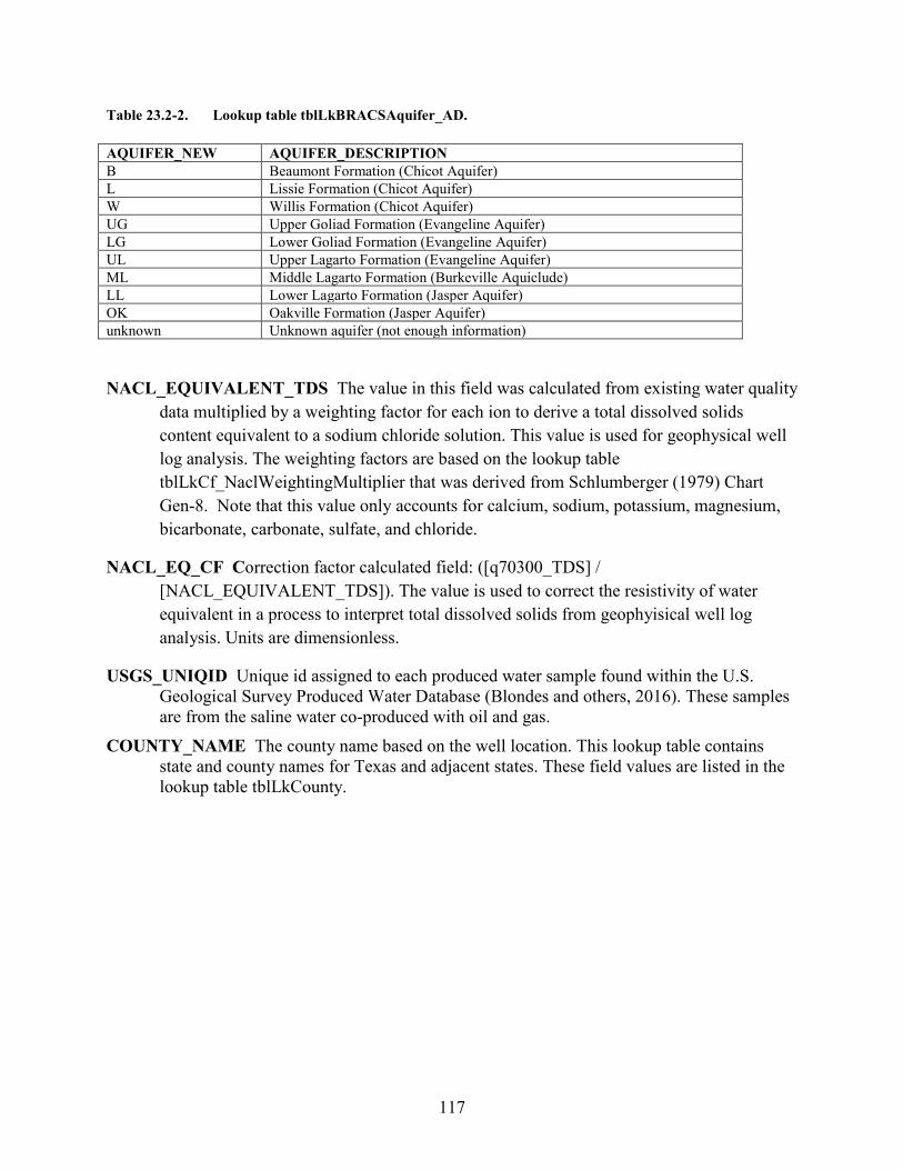
117
Table 23.2-2. Lookup table tblLkBRACSAquifer_AD. AQUIFER_NEW AQUIFER_DESCRIPTION B Beaumont Formation (Chicot Aquifer) L Lissie Formation (Chicot Aquifer) W Willis Formation (Chicot Aquifer) UG Upper Goliad Formation (Evangeline Aquifer) LG Lower Goliad Formation (Evangeline Aquifer) UL Upper Lagarto Formation (Evangeline Aquifer) ML Middle Lagarto Formation (Burkeville Aquiclude) LL Lower Lagarto Formation (Jasper Aquifer) OK Oakville Formation (Jasper Aquifer) unknown Unknown aquifer (not enough information)
NACL_EQUIVALENT_TDS The value in this field was calculated from existing water quality data multiplied by a weighting factor for each ion to derive a total dissolved solids content equivalent to a sodium chloride solution. This value is used for geophysical well log analysis. The weighting factors are based on the lookup table tblLkCf_NaclWeightingMultiplier that was derived from Schlumberger (1979) Chart Gen-8. Note that this value only accounts for calcium, sodium, potassium, magnesium, bicarbonate, carbonate, sulfate, and chloride.
NACL_EQ_CF Correction factor calculated field: ([q70300_TDS] / [NACL_EQUIVALENT_TDS]). The value is used to correct the resistivity of water equivalent in a process to interpret total dissolved solids from geophyisical well log analysis. Units are dimensionless.
USGS_UNIQID Unique id assigned to each produced water sample found within the U.S. Geological Survey Produced Water Database (Blondes and others, 2016). These samples are from the saline water co-produced with oil and gas.
COUNTY_NAME The county name based on the well location. This lookup table contains state and county names for Texas and adjacent states. These field values are listed in the lookup table tblLkCounty.
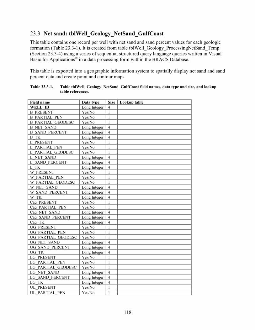
118
23.3 Net sand: tblWell_Geology_NetSand_GulfCoast This table contains one record per well with net sand and sand percent values for each geologic formation (Table 23.3-1). It is created from table tblWell_Geology_ProcessingNetSand_Temp (Section 23.3-4) using a series of sequential structured query language queries written in Visual Basic for Applications® in a data processing form within the BRACS Database. This table is exported into a geographic information system to spatially display net sand and sand percent data and create point and contour maps. Table 23.3-1. Table tblWell_Geology_NetSand_GulfCoast field names, data type and size, and lookup
table references. Field name Data type Size Lookup table WELL_ID Long Integer 4 B_PRESENT Yes/No 1 B_PARTIAL_PEN Yes/No 1 B_PARTIAL_GEODESC Yes/No 1 B_NET_SAND Long Integer 4 B_SAND_PERCENT Long Integer 4 B_TK Long Integer 4 L_PRESENT Yes/No 1 L_PARTIAL_PEN Yes/No 1 L_PARTIAL_GEODESC Yes/No 1 L_NET_SAND Long Integer 4 L_SAND_PERCENT Long Integer 4 L_TK Long Integer 4 W_PRESENT Yes/No 1 W_PARTIAL_PEN Yes/No 1 W_PARTIAL_GEODESC Yes/No 1 W_NET_SAND Long Integer 4 W_SAND_PERCENT Long Integer 4 W_TK Long Integer 4 Caq_PRESENT Yes/No 1 Caq_PARTIAL_PEN Yes/No 1 Caq_NET_SAND Long Integer 4 Caq_SAND_PERCENT Long Integer 4 Caq_TK Long Integer 4 UG_PRESENT Yes/No 1 UG_PARTIAL_PEN Yes/No 1 UG_PARTIAL_GEODESC Yes/No 1 UG_NET_SAND Long Integer 4 UG_SAND_PERCENT Long Integer 4 UG_TK Long Integer 4 LG_PRESENT Yes/No 1 LG_PARTIAL_PEN Yes/No 1 LG_PARTIAL_GEODESC Yes/No 1 LG_NET_SAND Long Integer 4 LG_SAND_PERCENT Long Integer 4 LG_TK Long Integer 4 UL_PRESENT Yes/No 1 UL_PARTIAL_PEN Yes/No 1

119
Field name Data type Size Lookup table UL_PARTIAL_GEODESC Yes/No 1 UL_NET_SAND Long Integer 4 UL_SAND_PERCENT Long Integer 4 UL_TK Long Integer 4 Eaq_PRESENT Yes/No 1 Eaq_PARTIAL_PEN Yes/No 1 Eaq_NET_SAND Long Integer 4 Eaq_SAND_PERCENT Long Integer 4 Eaq_TK Long Integer 4 ML_PRESENT Yes/No 1 ML_PARTIAL_PEN Yes/No 1 ML_PARTIAL_GEODESC Yes/No 1 ML_NET_SAND Long Integer 4 ML_SAND_PERCENT Long Integer 4 ML_TK Long Integer 4 LL_PRESENT Yes/No 1 LL_PARTIAL_PEN Yes/No 1 LL_PARTIAL_GEODESC Yes/No 1 LL_NET_SAND Long Integer 4 LL_SAND_PERCENT Long Integer 4 LL_TK Long Integer 4 OK_PRESENT Yes/No 1 OK_PARTIAL_PEN Yes/No 1 OK_PARTIAL_GEODESC Yes/No 1 OK_NET_SAND Long Integer 4 OK_SAND_PERCENT Long Integer 4 OK_TK Long Integer 4 Jaq_PRESENT Yes/No 1 Jaq_PARTIAL_PEN Yes/No 1 Jaq_NET_SAND Long Integer 4 Jaq_SAND_PERCENT Long Integer 4 Jaq_TK Long Integer 4 REMARKS Text 255 Field Descriptions WELL_ID Each record in the database is assigned a unique well ID (which is a long integer) in
this table. This is the key field in this table. B_PRESENT This field contains a value of Yes or No if the Beaumont Formation is present in
this well. B_PARTIAL_PEN This field contains a value of Yes or No if the Beaumont Formation is only
partially penetrated by this well. B_PARTIAL_GEODESC This field contains a value of Yes or No if the geologic description
is for less than 100 percent of the Beaumont Formation. This can occur if the upper part of the formation is cased, or if the geologic log for the lower part of the formation is not available.
B_NET_SAND This field contains an integer representing the total thickness of sand within the Beaumont Formation, in units of feet.

120
B_SAND_PERCENT The percent of sand within the Beaumont Formation, calculated field: (([B_NET_SAND] / [B_TK]) · 100).
B_TK Beaumont Formation thickness, calculated field: ([B_B_D] - [B_T_D]). The units are feet.
L_PRESENT This field contains a value of Yes or No if the Lissie Formation is present in this well.
L_PARTIAL_PEN This field contains a value of Yes or No if the Lissie Formation is only partially penetrated by this well.
L_PARTIAL_GEODESC This field contains a value of Yes or No if the geologic description is for less than 100 percent of the Lissie Formation. This can occur if the upper part of the formation is cased, or if the geologic log for the lower part of the formation is not available.
L_NET_SAND This field contains an integer representing the total thickness of sand within the Lissie Formation, in units of feet.
L_SAND_PERCENT The percent of sand within the Lissie Formation, calculated field: (([L_NET_SAND] / [L_TK]) · 100).
L_TK Lissie Formation thickness, calculated field: ([L_B_D] - [L_T_D]). The units are feet. W_PRESENT This field contains a value of Yes or No if the Willis Formation is present in this
well. W_PARTIAL_PEN This field contains a value of Yes or No if the Willis Formation is only
partially penetrated by this well. W_PARTIAL_GEODESC This field contains a value of Yes or No if the geologic description
is for less than 100 percent of the Willis Formation. This can occur if the upper part of the formation is cased, or if the geologic log for the lower part of the formation is not available.
W_NET_SAND This field contains an integer representing the total thickness of sand within the Willis Formation, in units of feet.
W_SAND_PERCENT The percent of sand within the Willis Formation, calculated field: (([W_NET_SAND] / [W_TK])· 100).
W_TK Willis Formation thickness, calculated field: ([W_B_D] - [W_T_D]). The units are feet. Caq_PRESENT This field contains a value of Yes or No if the Chicot Aquifer is present in this
well. Caq _PARTIAL_PEN This field contains a value of Yes or No if the Chicot Aquifer is only
partially penetrated by this well. Caq _NET_SAND This field contains an integer representing the total thickness of sand within
the Chicot Aquifer, in units of feet. Caq _SAND_PERCENT The percent of sand within the Chicot Aquifer, calculated field:
(([Caq_NET_SAND] / Caq_TK])· 100). Caq _TK Chicot Aquifer thickness, calculated field: ([W_B_D] - [B_T_D]). The units are feet.
121
UG_PRESENT This field contains a value of Yes or No if the Upper Goliad Formation is present in this well.
UG_PARTIAL_PEN This field contains a value of Yes or No if the Upper Goliad Formation is only partially penetrated by this well.
UG_PARTIAL_GEODESC This field contains a value of Yes or No if the geologic description is for less than 100 percent of the Upper Goliad Formation. This can occur if the upper part of the formation is cased, or if the geologic log for the lower part of the formation is not available.
UG_NET_SAND This field contains an integer representing the total thickness of sand within the Upper Goliad Formation, in units of feet.
UG_SAND_PERCENT The percent of sand within the Upper Goliad Formation, calculated field: (([UG_NET_SAND] / [UG_TK])· 100).
UG_TK Upper Goliad Formation thickness, calculated field: ([UG_B_D] - [UG_T_D]). The units are feet.
LG_PRESENT This field contains a value of Yes or No if the Lower Goliad Formation is present in this well.
LG_PARTIAL_PEN This field contains a value of Yes or No if the Lower Goliad Formation is only partially penetrated by this well.
LG_PARTIAL_GEODESC This field contains a value of Yes or No if the geologic description is for less than 100 percent of the Lower Goliad Formation. This can occur if the upper part of the formation is cased, or if the geologic log for the lower part of the formation is not available.
LG_NET_SAND This field contains an integer representing the total thickness of sand within the Lower Goliad Formation, in units of feet.
LG_SAND_PERCENT The percent of sand within the Lower Goliad Formation, calculated field: (([LG_NET_SAND] / [LG_TK]) · 100).
LG_TK Lower Goliad Formation thickness, calculated field: ([LG_B_D] - [LG_T_D]). The units are feet.
UL_PRESENT This field contains a value of Yes or No if the Upper Lagarto Formation is present in this well.
UL_PARTIAL_PEN This field contains a value of Yes or No if the Upper Lagarto Formation is only partially penetrated by this well.
UL_PARTIAL_GEODESC This field contains a value of Yes or No if the geologic description is for less than 100 percent of the Upper Lagarto Formation. This can occur if the upper part of the formation is cased, or if the geologic log for the lower part of the formation is not available.
UL_NET_SAND This field contains an integer representing the total thickness of sand within the Upper Lagarto Formation, in units of feet.
UL_SAND_PERCENT The percent of sand within the Upper Lagarto Formation, calculated field: (([UL_NET_SAND] / [UL_TK]) · 100).
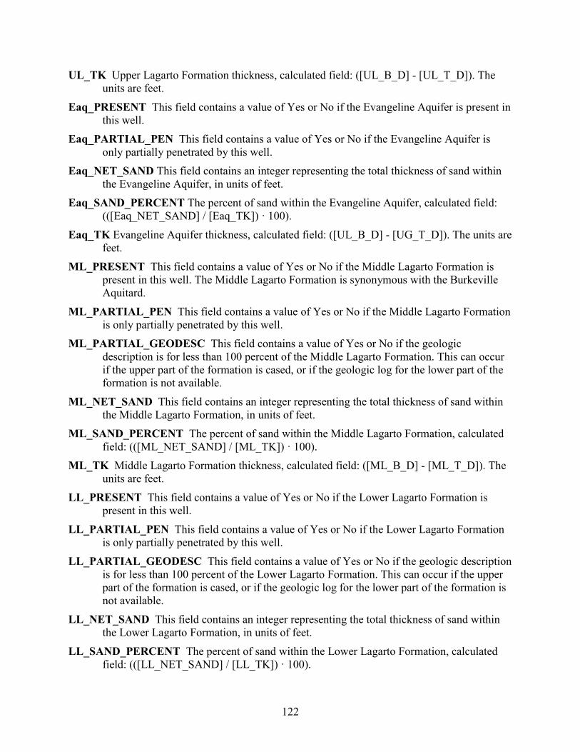
122
UL_TK Upper Lagarto Formation thickness, calculated field: ([UL_B_D] - [UL_T_D]). The units are feet.
Eaq_PRESENT This field contains a value of Yes or No if the Evangeline Aquifer is present in this well.
Eaq_PARTIAL_PEN This field contains a value of Yes or No if the Evangeline Aquifer is only partially penetrated by this well.
Eaq_NET_SAND This field contains an integer representing the total thickness of sand within the Evangeline Aquifer, in units of feet.
Eaq_SAND_PERCENT The percent of sand within the Evangeline Aquifer, calculated field: (([Eaq_NET_SAND] / [Eaq_TK]) · 100).
Eaq_TK Evangeline Aquifer thickness, calculated field: ([UL_B_D] - [UG_T_D]). The units are feet.
ML_PRESENT This field contains a value of Yes or No if the Middle Lagarto Formation is present in this well. The Middle Lagarto Formation is synonymous with the Burkeville Aquitard.
ML_PARTIAL_PEN This field contains a value of Yes or No if the Middle Lagarto Formation is only partially penetrated by this well.
ML_PARTIAL_GEODESC This field contains a value of Yes or No if the geologic description is for less than 100 percent of the Middle Lagarto Formation. This can occur if the upper part of the formation is cased, or if the geologic log for the lower part of the formation is not available.
ML_NET_SAND This field contains an integer representing the total thickness of sand within the Middle Lagarto Formation, in units of feet.
ML_SAND_PERCENT The percent of sand within the Middle Lagarto Formation, calculated field: (([ML_NET_SAND] / [ML_TK]) · 100).
ML_TK Middle Lagarto Formation thickness, calculated field: ([ML_B_D] - [ML_T_D]). The units are feet.
LL_PRESENT This field contains a value of Yes or No if the Lower Lagarto Formation is present in this well.
LL_PARTIAL_PEN This field contains a value of Yes or No if the Lower Lagarto Formation is only partially penetrated by this well.
LL_PARTIAL_GEODESC This field contains a value of Yes or No if the geologic description is for less than 100 percent of the Lower Lagarto Formation. This can occur if the upper part of the formation is cased, or if the geologic log for the lower part of the formation is not available.
LL_NET_SAND This field contains an integer representing the total thickness of sand within the Lower Lagarto Formation, in units of feet.
LL_SAND_PERCENT The percent of sand within the Lower Lagarto Formation, calculated field: (([LL_NET_SAND] / [LL_TK]) · 100).
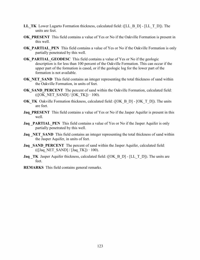
123
LL_TK Lower Lagarto Formation thickness, calculated field: ([LL_B_D] - [LL_T_D]). The units are feet.
OK_PRESENT This field contains a value of Yes or No if the Oakville Formation is present in this well.
OK_PARTIAL_PEN This field contains a value of Yes or No if the Oakville Formation is only partially penetrated by this well.
OK_PARTIAL_GEODESC This field contains a value of Yes or No if the geologic description is for less than 100 percent of the Oakville Formation. This can occur if the upper part of the formation is cased, or if the geologic log for the lower part of the formation is not available.
OK_NET_SAND This field contains an integer representing the total thickness of sand within the Oakville Formation, in units of feet.
OK_SAND_PERCENT The percent of sand within the Oakville Formation, calculated field: (([OK_NET_SAND] / [OK_TK]) · 100).
OK_TK Oakville Formation thickness, calculated field: ([OK_B_D] - [OK_T_D]). The units are feet.
Jaq_PRESENT This field contains a value of Yes or No if the Jasper Aquifer is present in this well.
Jaq _PARTIAL_PEN This field contains a value of Yes or No if the Jasper Aquifer is only partially penetrated by this well.
Jaq _NET_SAND This field contains an integer representing the total thickness of sand within the Jasper Aquifer, in units of feet.
Jaq _SAND_PERCENT The percent of sand within the Jasper Aquifer, calculated field: (([Jaq_NET_SAND] / [Jaq_TK]) · 100).
Jaq _TK Jasper Aquifer thickness, calculated field: ([OK_B_D] - [LL_T_D]). The units are feet.
REMARKS This field contains general remarks.
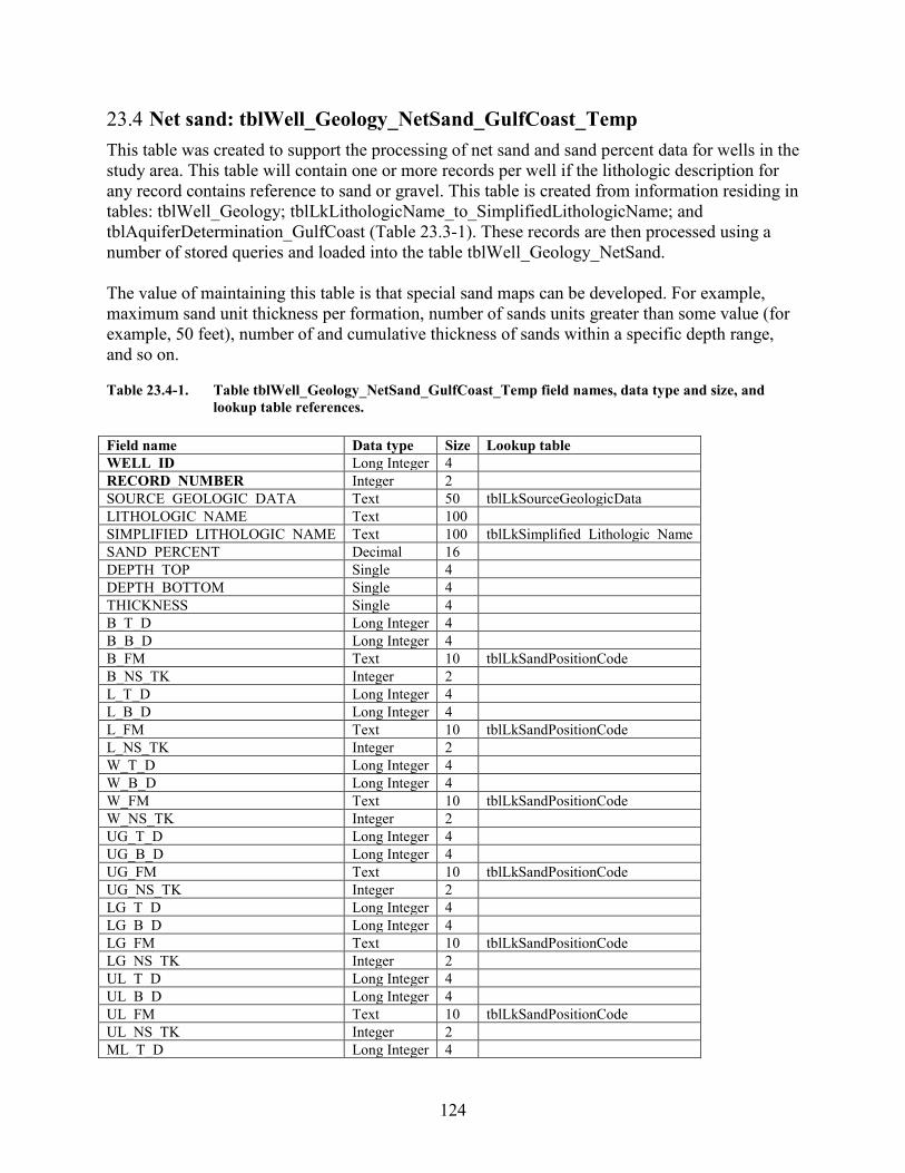
124
23.4 Net sand: tblWell_Geology_NetSand_GulfCoast_Temp This table was created to support the processing of net sand and sand percent data for wells in the study area. This table will contain one or more records per well if the lithologic description for any record contains reference to sand or gravel. This table is created from information residing in tables: tblWell_Geology; tblLkLithologicName_to_SimplifiedLithologicName; and tblAquiferDetermination_GulfCoast (Table 23.3-1). These records are then processed using a number of stored queries and loaded into the table tblWell_Geology_NetSand. The value of maintaining this table is that special sand maps can be developed. For example, maximum sand unit thickness per formation, number of sands units greater than some value (for example, 50 feet), number of and cumulative thickness of sands within a specific depth range, and so on. Table 23.4-1. Table tblWell_Geology_NetSand_GulfCoast_Temp field names, data type and size, and
lookup table references. Field name Data type Size Lookup table WELL_ID Long Integer 4 RECORD_NUMBER Integer 2 SOURCE_GEOLOGIC_DATA Text 50 tblLkSourceGeologicData LITHOLOGIC_NAME Text 100 SIMPLIFIED_LITHOLOGIC_NAME Text 100 tblLkSimplified_Lithologic_Name SAND_PERCENT Decimal 16 DEPTH_TOP Single 4 DEPTH_BOTTOM Single 4 THICKNESS Single 4 B_T_D Long Integer 4 B_B_D Long Integer 4 B_FM Text 10 tblLkSandPositionCode B_NS_TK Integer 2 L_T_D Long Integer 4 L_B_D Long Integer 4 L_FM Text 10 tblLkSandPositionCode L_NS_TK Integer 2 W_T_D Long Integer 4 W_B_D Long Integer 4 W_FM Text 10 tblLkSandPositionCode W_NS_TK Integer 2 UG_T_D Long Integer 4 UG_B_D Long Integer 4 UG_FM Text 10 tblLkSandPositionCode UG_NS_TK Integer 2 LG_T_D Long Integer 4 LG_B_D Long Integer 4 LG_FM Text 10 tblLkSandPositionCode LG_NS_TK Integer 2 UL_T_D Long Integer 4 UL_B_D Long Integer 4 UL_FM Text 10 tblLkSandPositionCode UL_NS_TK Integer 2 ML_T_D Long Integer 4
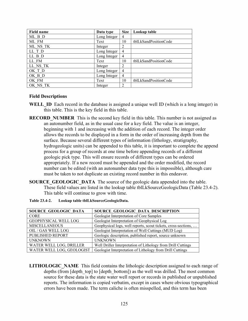
125
Field name Data type Size Lookup table ML_B_D Long Integer 4 ML_FM Text 10 tblLkSandPositionCode ML_NS_TK Integer 2 LL_T_D Long Integer 4 LL_B_D Long Integer 4 LL_FM Text 10 tblLkSandPositionCode LL_NS_TK Integer 2 OK_T_D Long Integer 4 OK_B_D Long Integer 4 OK_FM Text 10 tblLkSandPositionCode OK_NS_TK Integer 2 Field Descriptions WELL_ID Each record in the database is assigned a unique well ID (which is a long integer) in
this table. This is the key field in this table. RECORD_NUMBER This is the second key field in this table. This number is not assigned as
an autonumber field, as in the usual case for a key field. The value is an integer, beginning with 1 and increasing with the addition of each record. The integer order allows the records to be displayed in a form in the order of increasing depth from the surface. Because several different types of information (lithology, stratigraphy, hydrogeologic units) can be appended to this table, it is important to complete the append process for a group of records at one time before appending records of a different geologic pick type. This will ensure records of different types can be ordered appropriately. If a new record must be appended and the order modified, the record number can be edited (with an autonumber data type this is impossible), although care must be taken to not duplicate an existing record number in this endeavor.
SOURCE_GEOLOGIC_DATA The source of the geologic data appended into the table. These field values are listed in the lookup table tblLkSourceGeologicData (Table 23.4-2). This table will continue to grow with time.
Table 23.4-2. Lookup table tblLkSourceGeologicData. SOURCE_GEOLOGIC_DATA SOURCE_GEOLOGIC_DATA_DESCRIPTION CORE Geologist Interpretation of Core Samples GEOPHYSICAL WELL LOG Geologist Interpretation of Geophysical Log MISCELLANEOUS Geophysical logs, well reports, scout tickets, cross-sections, … OIL / GAS WELL LOG Geologist Interpretation of Well Cuttings (MUD Log) PUBLISHED REPORT Geologic description, published report, source unknown UNKNOWN UNKNOWN WATER WELL LOG, DRILLER Well Driller Interpretation of Lithology from Drill Cuttings WATER WELL LOG, GEOLOGIST Geologist Interpretation of Lithology from Drill Cuttings
LITHOLOGIC_NAME This field contains the lithologic description assigned to each range of depths (from [depth_top] to [depth_bottom]) as the well was drilled. The most common source for these data is the state water well report or records in published or unpublished reports. The information is copied verbatim, except in cases where obvious typographical errors have been made. The term caliche is often misspelled, and this term has been
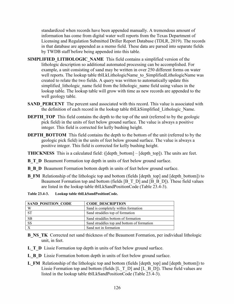
126
standardized when records have been appended manually. A tremendous amount of information has come from digital water well reports from the Texas Department of Licensing and Regulation Submitted Driller Report Database (TDLR, 2019). The records in that database are appended as a memo field. These data are parsed into separate fields by TWDB staff before being appended into this table.
SIMPLIFIED_LITHOLOGIC_NAME This field contains a simplified version of the lithologic description so additional automated processing can be accomplished. For example, a unit consisting of sand may be written in over 250 different forms on water well reports. The lookup table tblLkLithologicName_to_SimplifiedLithologicName was created to relate the two fields. A query was written to automatically update this simplified_lithologic_name field from the lithologic_name field using values in the lookup table. The lookup table will grow with time as new records are appended to the well geology table.
SAND_PERCENT The percent sand associated with this record. This value is associated with the definition of each record in the lookup table tblLkSimplified_Lithologic_Name.
DEPTH_TOP This field contains the depth to the top of the unit (referred to by the geologic pick field) in the units of feet below ground surface. The value is always a positive integer. This field is corrected for kelly bushing height.
DEPTH_BOTTOM This field contains the depth to the bottom of the unit (referred to by the geologic pick field) in the units of feet below ground surface. The value is always a positive integer. This field is corrected for kelly bushing height.
THICKNESS This is a calculated field: ([depth_bottom] – [depth_top]). The units are feet. B_T_D Beaumont Formation top depth in units of feet below ground surface. B_B_D Beaumont Formation bottom depth in units of feet below ground surface. B_FM Relationship of the lithologic top and bottom (fields [depth_top] and [depth_bottom]) to
Beaumont Formation top and bottom (fields [B_T_D] and [B_B_D]). These field values are listed in the lookup table tblLkSandPositionCode (Table 23.4-3).
Table 23.4-3. Lookup table tblLkSandPositionCode. SAND_POSITION_CODE CODE_DESCRIPTION W Sand is completely within formation ST Sand straddles top of formation SB Sand straddles bottom of formation SS Sand straddles top and bottom of formation X Sand not in formation
B_NS_TK Corrected net sand thickness of the Beaumont Formation, per individual lithologic unit, in feet.
L_T_D Lissie Formation top depth in units of feet below ground surface. L_B_D Lissie Formation bottom depth in units of feet below ground surface. L_FM Relationship of the lithologic top and bottom (fields [depth_top] and [depth_bottom]) to
Lissie Formation top and bottom (fields [L_T_D] and [L_B_D]). These field values are listed in the lookup table tblLkSandPositionCode (Table 23.4-3).
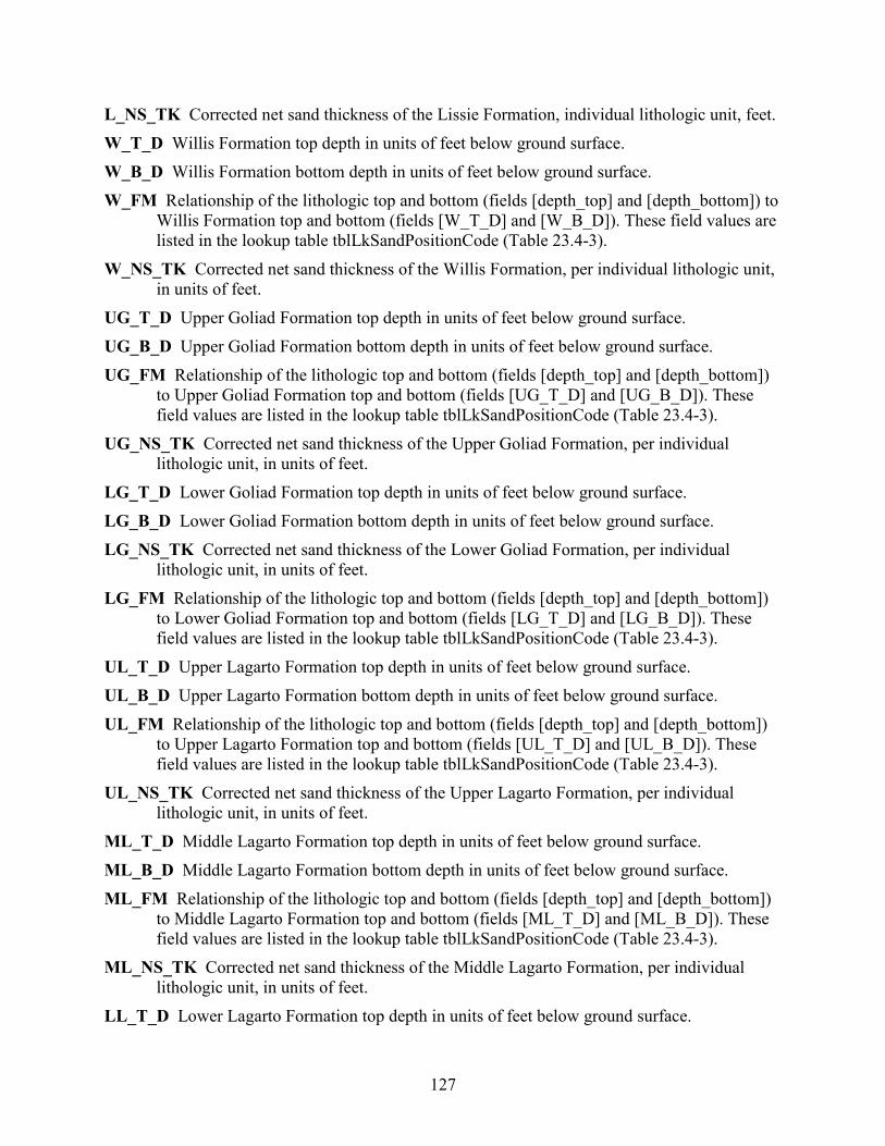
127
L_NS_TK Corrected net sand thickness of the Lissie Formation, individual lithologic unit, feet. W_T_D Willis Formation top depth in units of feet below ground surface. W_B_D Willis Formation bottom depth in units of feet below ground surface. W_FM Relationship of the lithologic top and bottom (fields [depth_top] and [depth_bottom]) to
Willis Formation top and bottom (fields [W_T_D] and [W_B_D]). These field values are listed in the lookup table tblLkSandPositionCode (Table 23.4-3).
W_NS_TK Corrected net sand thickness of the Willis Formation, per individual lithologic unit, in units of feet.
UG_T_D Upper Goliad Formation top depth in units of feet below ground surface. UG_B_D Upper Goliad Formation bottom depth in units of feet below ground surface. UG_FM Relationship of the lithologic top and bottom (fields [depth_top] and [depth_bottom])
to Upper Goliad Formation top and bottom (fields [UG_T_D] and [UG_B_D]). These field values are listed in the lookup table tblLkSandPositionCode (Table 23.4-3).
UG_NS_TK Corrected net sand thickness of the Upper Goliad Formation, per individual lithologic unit, in units of feet.
LG_T_D Lower Goliad Formation top depth in units of feet below ground surface. LG_B_D Lower Goliad Formation bottom depth in units of feet below ground surface. LG_NS_TK Corrected net sand thickness of the Lower Goliad Formation, per individual
lithologic unit, in units of feet. LG_FM Relationship of the lithologic top and bottom (fields [depth_top] and [depth_bottom])
to Lower Goliad Formation top and bottom (fields [LG_T_D] and [LG_B_D]). These field values are listed in the lookup table tblLkSandPositionCode (Table 23.4-3).
UL_T_D Upper Lagarto Formation top depth in units of feet below ground surface. UL_B_D Upper Lagarto Formation bottom depth in units of feet below ground surface. UL_FM Relationship of the lithologic top and bottom (fields [depth_top] and [depth_bottom])
to Upper Lagarto Formation top and bottom (fields [UL_T_D] and [UL_B_D]). These field values are listed in the lookup table tblLkSandPositionCode (Table 23.4-3).
UL_NS_TK Corrected net sand thickness of the Upper Lagarto Formation, per individual lithologic unit, in units of feet.
ML_T_D Middle Lagarto Formation top depth in units of feet below ground surface. ML_B_D Middle Lagarto Formation bottom depth in units of feet below ground surface. ML_FM Relationship of the lithologic top and bottom (fields [depth_top] and [depth_bottom])
to Middle Lagarto Formation top and bottom (fields [ML_T_D] and [ML_B_D]). These field values are listed in the lookup table tblLkSandPositionCode (Table 23.4-3).
ML_NS_TK Corrected net sand thickness of the Middle Lagarto Formation, per individual lithologic unit, in units of feet.
LL_T_D Lower Lagarto Formation top depth in units of feet below ground surface.

128
LL_B_D Lower Lagarto Formation bottom depth in units of feet below ground surface. LL_FM Relationship of the lithologic top and bottom (fields [depth_top] and [depth_bottom])
to Lower Lagarto Formation top and bottom (fields [LL_T_D] and [LL_B_D]). These field values are listed in the lookup table tblLkSandPositionCode (Table 23.4-3).
LL_NS_TK Corrected net sand thickness of the Lower Lagarto Formation, per individual lithologic unit, in units of feet.
OK_T_D Oakville Formation top depth in units of feet below ground surface. OK_B_D Oakville Formation bottom depth in units of feet below ground surface. OK_FM Relationship of the lithologic top and bottom (fields [depth_top] and [depth_bottom])
to Oakville Formation top and bottom (fields [OK_T_D] and [OK_B_D]). These field values are listed in the lookup table tblLkSandPositionCode (Table 23.4-3).
OK_NS_TK Corrected net sand thickness of the Oakville Formation, per individual lithologic unit, in units of feet.
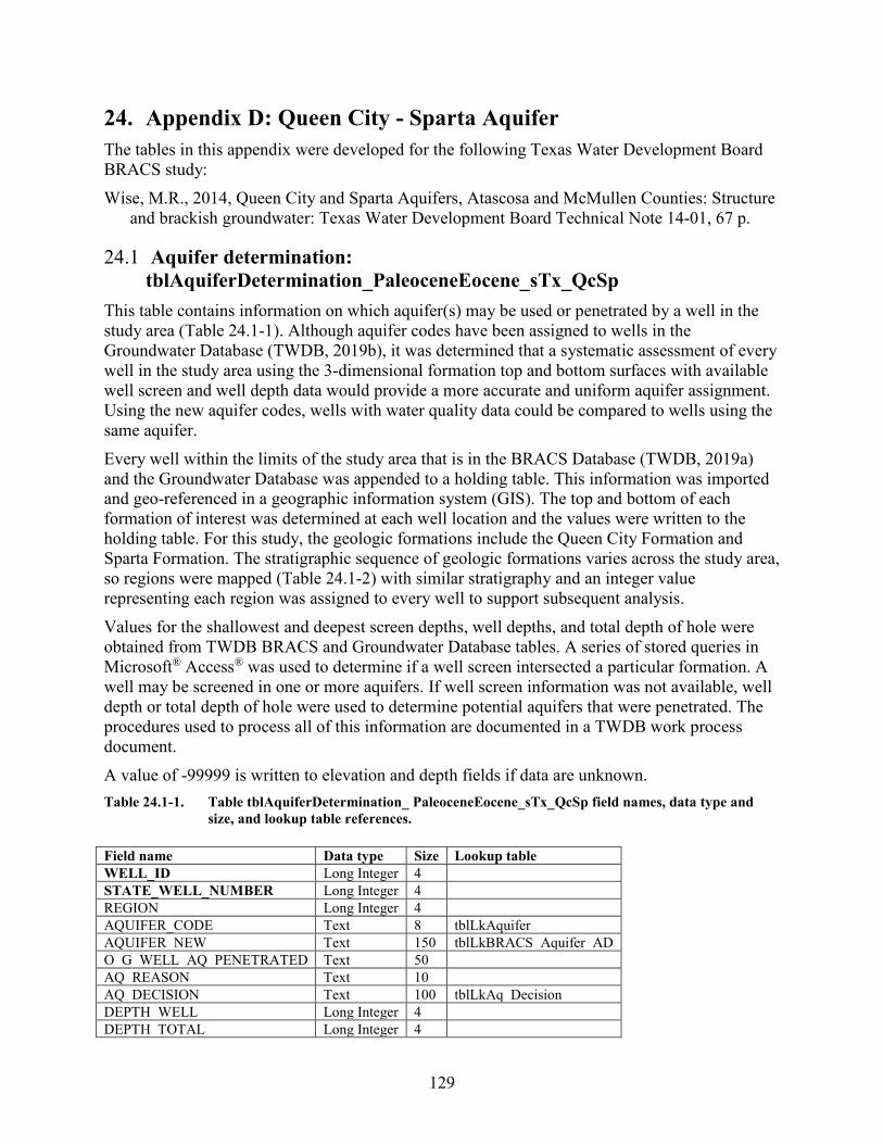
129
24. Appendix D: Queen City - Sparta Aquifer The tables in this appendix were developed for the following Texas Water Development Board BRACS study: Wise, M.R., 2014, Queen City and Sparta Aquifers, Atascosa and McMullen Counties: Structure
and brackish groundwater: Texas Water Development Board Technical Note 14-01, 67 p.
24.1 Aquifer determination: tblAquiferDetermination_PaleoceneEocene_sTx_QcSp
This table contains information on which aquifer(s) may be used or penetrated by a well in the study area (Table 24.1-1). Although aquifer codes have been assigned to wells in the Groundwater Database (TWDB, 2019b), it was determined that a systematic assessment of every well in the study area using the 3-dimensional formation top and bottom surfaces with available well screen and well depth data would provide a more accurate and uniform aquifer assignment. Using the new aquifer codes, wells with water quality data could be compared to wells using the same aquifer. Every well within the limits of the study area that is in the BRACS Database (TWDB, 2019a) and the Groundwater Database was appended to a holding table. This information was imported and geo-referenced in a geographic information system (GIS). The top and bottom of each formation of interest was determined at each well location and the values were written to the holding table. For this study, the geologic formations include the Queen City Formation and Sparta Formation. The stratigraphic sequence of geologic formations varies across the study area, so regions were mapped (Table 24.1-2) with similar stratigraphy and an integer value representing each region was assigned to every well to support subsequent analysis. Values for the shallowest and deepest screen depths, well depths, and total depth of hole were obtained from TWDB BRACS and Groundwater Database tables. A series of stored queries in Microsoft® Access® was used to determine if a well screen intersected a particular formation. A well may be screened in one or more aquifers. If well screen information was not available, well depth or total depth of hole were used to determine potential aquifers that were penetrated. The procedures used to process all of this information are documented in a TWDB work process document. A value of -99999 is written to elevation and depth fields if data are unknown. Table 24.1-1. Table tblAquiferDetermination_ PaleoceneEocene_sTx_QcSp field names, data type and
size, and lookup table references. Field name Data type Size Lookup table WELL_ID Long Integer 4 STATE_WELL_NUMBER Long Integer 4 REGION Long Integer 4 AQUIFER_CODE Text 8 tblLkAquifer AQUIFER_NEW Text 150 tblLkBRACS_Aquifer_AD O_G_WELL_AQ_PENETRATED Text 50 AQ_REASON Text 10 AQ_DECISION Text 100 tblLkAq_Decision DEPTH_WELL Long Integer 4 DEPTH_TOTAL Long Integer 4
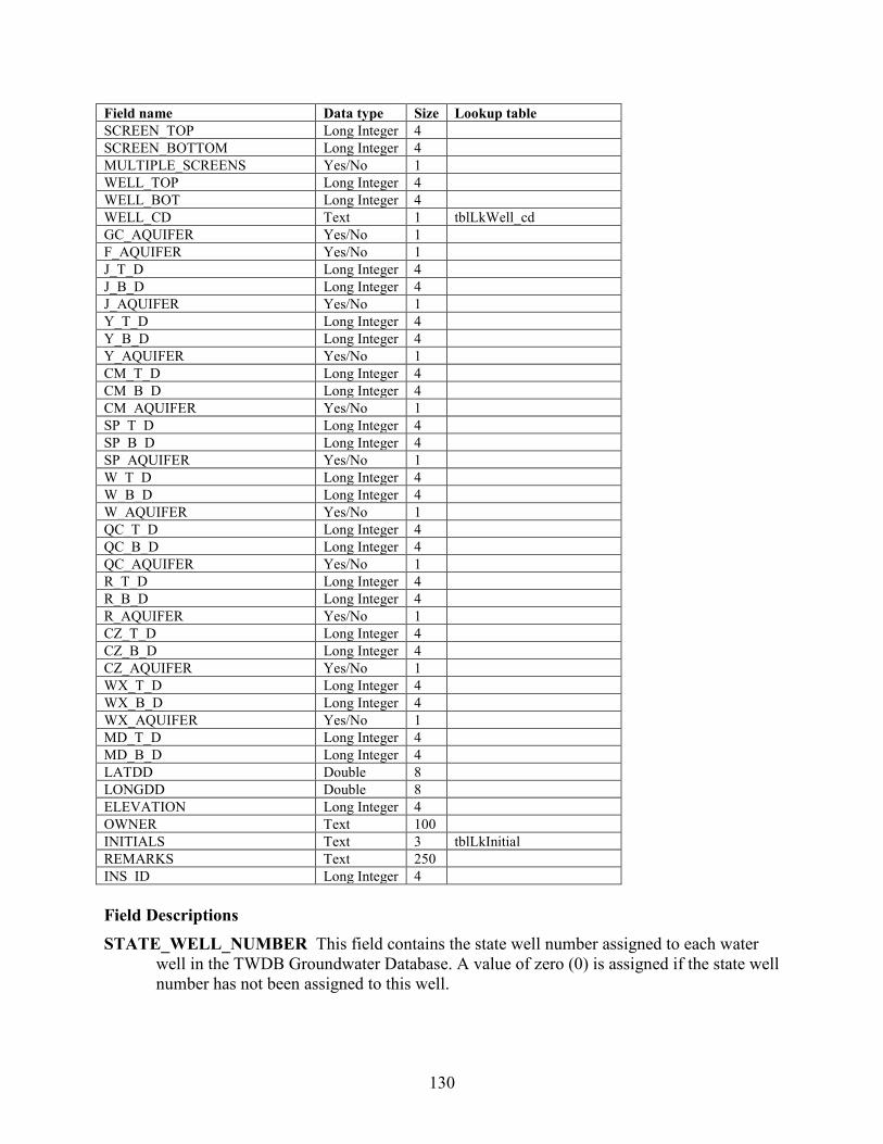
130
Field name Data type Size Lookup table SCREEN_TOP Long Integer 4 SCREEN_BOTTOM Long Integer 4 MULTIPLE_SCREENS Yes/No 1 WELL_TOP Long Integer 4 WELL_BOT Long Integer 4 WELL_CD Text 1 tblLkWell_cd GC_AQUIFER Yes/No 1 F_AQUIFER Yes/No 1 J_T_D Long Integer 4 J_B_D Long Integer 4 J_AQUIFER Yes/No 1 Y_T_D Long Integer 4 Y_B_D Long Integer 4 Y_AQUIFER Yes/No 1 CM_T_D Long Integer 4 CM_B_D Long Integer 4 CM_AQUIFER Yes/No 1 SP_T_D Long Integer 4 SP_B_D Long Integer 4 SP_AQUIFER Yes/No 1 W_T_D Long Integer 4 W_B_D Long Integer 4 W_AQUIFER Yes/No 1 QC_T_D Long Integer 4 QC_B_D Long Integer 4 QC_AQUIFER Yes/No 1 R_T_D Long Integer 4 R_B_D Long Integer 4 R_AQUIFER Yes/No 1 CZ_T_D Long Integer 4 CZ_B_D Long Integer 4 CZ_AQUIFER Yes/No 1 WX_T_D Long Integer 4 WX_B_D Long Integer 4 WX_AQUIFER Yes/No 1 MD_T_D Long Integer 4 MD_B_D Long Integer 4 LATDD Double 8 LONGDD Double 8 ELEVATION Long Integer 4 OWNER Text 100 INITIALS Text 3 tblLkInitial REMARKS Text 250 INS_ID Long Integer 4 Field Descriptions STATE_WELL_NUMBER This field contains the state well number assigned to each water
well in the TWDB Groundwater Database. A value of zero (0) is assigned if the state well number has not been assigned to this well.

131
WELL_ID Each record in the database is assigned a unique well ID (which is a long integer) in this table. A value of zero (0) is assigned if the well ID has not been assigned to this well.
REGION This field contains an integer value representing a region of the Queen City - Sparta study area that has a similar stratigraphic sequence. The regions are bounded by the outcrops of the geologic formations (Table 24.1-2).
Table 24.1-2. Stratigraphic sequence of geologic formations within each region of the study area. Yellow cells represent aquifers, and green cells are not aquifers.
System Region
1 Region
2 Region
3 Region
4 Region
5 Region
6 Oligocene Eocene Sparta Weches Weches Queen City Queen City Queen City
Reklaw Reklaw Reklaw Reklaw Carrizo Carrizo Carrizo Carrizo Carrizo Wilcox Wilcox Wilcox Wilcox Wilcox Wilcox Paleocene Midway Midway Midway Midway Midway Midway System Region
7 Region
8 Region
9 Region
10 Region
11 Gulf Coast
Fms
Oligocene Frio Frio Jackson Jackson Jackson Yegua Yegua Yegua Yegua Cook
Mountain Cook Mountain
Cook Mountain
Cook Mountain
Cook Mountain
Eocene Sparta Sparta Sparta Sparta Sparta Weches Weches Weches Weches Weches Queen City Queen City Queen City Queen City Queen City
Reklaw Reklaw Reklaw Reklaw Reklaw Carrizo Carrizo Carrizo Carrizo Carrizo Wilcox Wilcox Wilcox Wilcox Wilcox Paleocene Midway Midway Midway Midway Midway
AQUIFER_CODE This field contains an aquifer code that has been assigned to every water
well in the TWDB Groundwater Database. These field values are listed in the lookup table tblLkAquifer, derived from a similar lookup table in the Groundwater Database.
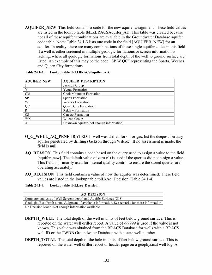
132
AQUIFER_NEW This field contains a code for the new aquifer assignment. These field values are listed in the lookup table tblLkBRACSAquifer_AD. This table was created because not all of these aquifer combinations are available in the Groundwater Database aquifer code table. Note: Table 24.1-3 lists one code in the field [AQUIFER_NEW] for an aquifer. In reality, there are many combinations of these single aquifer codes in this field if a well is either screened in multiple geologic formations or screen information is lacking, where all geologic formations from total depth of the well to ground surface are listed. An example of this may be the code “SP W QC” representing the Sparta, Weches, and Queen City formations.
Table 24.1-3. Lookup table tblLkBRACSAquifer_AD. AQUIFER_NEW AQUIFER_DESCRIPTION J Jackson Group Y Yegua Formation CM Cook Mountain Formation SP Sparta Formation W Weches Formation QC Queen City Formation R Reklaw Formation CZ Carrizo Formation WX Wilcox Group X Unknown aquifer (not enough information)
O_G_WELL_AQ_PENETRATED If well was drilled for oil or gas, list the deepest Tertiary
aquifer penetrated by drilling (Jackson through Wilcox). If no assessment is made, the field is null.
AQ_REASON This field contains a code based on the query used to assign a value to the field [aquifer_new]. The default value of zero (0) is used if the queries did not assign a value. This field is primarily used for internal quality control to ensure the stored queries are operating accurately.
AQ_DECISION This field contains a value of how the aquifer was determined. These field values are listed in the lookup table tblLkAq_Decision (Table 24.1-4).
Table 24.1-4. Lookup table tblLkAq_Decision.
AQ_DECISION Computer analysis of Well Screen (depth) and Aquifer Surfaces (GIS) Geologist Best Professional Judgment of available information. See remarks for more information No Decision Made. Not enough information available DEPTH_WELL The total depth of the well in units of feet below ground surface. This is
reported on the water well driller report. A value of -99999 is used if the value is not known. This value was obtained from the BRACS Database for wells with a BRACS well ID or the TWDB Groundwater Database with a state well number.
DEPTH_TOTAL The total depth of the hole in units of feet below ground surface. This is reported on the water well driller report or header page on a geophysical well log. A
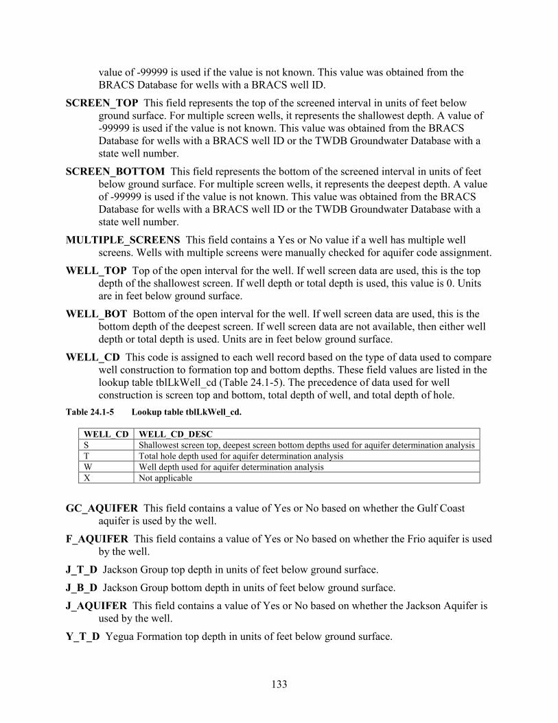
133
value of -99999 is used if the value is not known. This value was obtained from the BRACS Database for wells with a BRACS well ID.
SCREEN_TOP This field represents the top of the screened interval in units of feet below ground surface. For multiple screen wells, it represents the shallowest depth. A value of -99999 is used if the value is not known. This value was obtained from the BRACS Database for wells with a BRACS well ID or the TWDB Groundwater Database with a state well number.
SCREEN_BOTTOM This field represents the bottom of the screened interval in units of feet below ground surface. For multiple screen wells, it represents the deepest depth. A value of -99999 is used if the value is not known. This value was obtained from the BRACS Database for wells with a BRACS well ID or the TWDB Groundwater Database with a state well number.
MULTIPLE_SCREENS This field contains a Yes or No value if a well has multiple well screens. Wells with multiple screens were manually checked for aquifer code assignment.
WELL_TOP Top of the open interval for the well. If well screen data are used, this is the top depth of the shallowest screen. If well depth or total depth is used, this value is 0. Units are in feet below ground surface.
WELL_BOT Bottom of the open interval for the well. If well screen data are used, this is the bottom depth of the deepest screen. If well screen data are not available, then either well depth or total depth is used. Units are in feet below ground surface.
WELL_CD This code is assigned to each well record based on the type of data used to compare well construction to formation top and bottom depths. These field values are listed in the lookup table tblLkWell_cd (Table 24.1-5). The precedence of data used for well construction is screen top and bottom, total depth of well, and total depth of hole.
Table 24.1-5 Lookup table tblLkWell_cd.
GC_AQUIFER This field contains a value of Yes or No based on whether the Gulf Coast
aquifer is used by the well. F_AQUIFER This field contains a value of Yes or No based on whether the Frio aquifer is used
by the well. J_T_D Jackson Group top depth in units of feet below ground surface. J_B_D Jackson Group bottom depth in units of feet below ground surface. J_AQUIFER This field contains a value of Yes or No based on whether the Jackson Aquifer is
used by the well. Y_T_D Yegua Formation top depth in units of feet below ground surface.
WELL_CD WELL_CD_DESC S Shallowest screen top, deepest screen bottom depths used for aquifer determination analysis T Total hole depth used for aquifer determination analysis W Well depth used for aquifer determination analysis X Not applicable
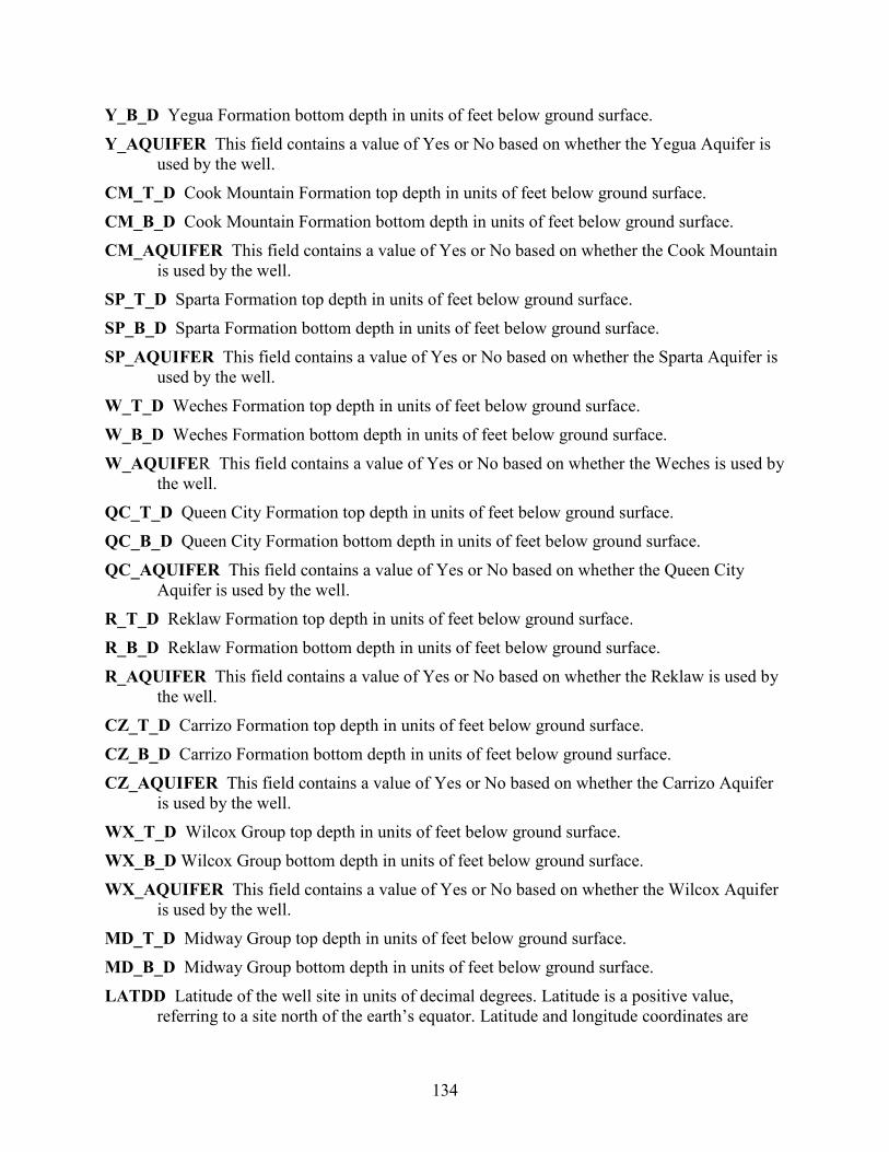
134
Y_B_D Yegua Formation bottom depth in units of feet below ground surface. Y_AQUIFER This field contains a value of Yes or No based on whether the Yegua Aquifer is
used by the well. CM_T_D Cook Mountain Formation top depth in units of feet below ground surface. CM_B_D Cook Mountain Formation bottom depth in units of feet below ground surface. CM_AQUIFER This field contains a value of Yes or No based on whether the Cook Mountain
is used by the well. SP_T_D Sparta Formation top depth in units of feet below ground surface. SP_B_D Sparta Formation bottom depth in units of feet below ground surface. SP_AQUIFER This field contains a value of Yes or No based on whether the Sparta Aquifer is
used by the well. W_T_D Weches Formation top depth in units of feet below ground surface. W_B_D Weches Formation bottom depth in units of feet below ground surface. W_AQUIFER This field contains a value of Yes or No based on whether the Weches is used by
the well. QC_T_D Queen City Formation top depth in units of feet below ground surface. QC_B_D Queen City Formation bottom depth in units of feet below ground surface. QC_AQUIFER This field contains a value of Yes or No based on whether the Queen City
Aquifer is used by the well. R_T_D Reklaw Formation top depth in units of feet below ground surface. R_B_D Reklaw Formation bottom depth in units of feet below ground surface. R_AQUIFER This field contains a value of Yes or No based on whether the Reklaw is used by
the well. CZ_T_D Carrizo Formation top depth in units of feet below ground surface. CZ_B_D Carrizo Formation bottom depth in units of feet below ground surface. CZ_AQUIFER This field contains a value of Yes or No based on whether the Carrizo Aquifer
is used by the well. WX_T_D Wilcox Group top depth in units of feet below ground surface. WX_B_D Wilcox Group bottom depth in units of feet below ground surface. WX_AQUIFER This field contains a value of Yes or No based on whether the Wilcox Aquifer
is used by the well. MD_T_D Midway Group top depth in units of feet below ground surface. MD_B_D Midway Group bottom depth in units of feet below ground surface. LATDD Latitude of the well site in units of decimal degrees. Latitude is a positive value,
referring to a site north of the earth’s equator. Latitude and longitude coordinates are
135
obtained from multiple sources. Latitude is obtained is based on a North American Datum of 1983. This value was obtained from the well location table.
LONGDD Longitude of the well site in units of decimal degrees. Longitude is a negative value, referring to a site west of the Prime Meridian in Greenwich, United Kingdom. Latitude and longitude coordinates are obtained from multiple sources. Longitude is based on a North American Datum of 1983. This value was obtained from the well location table.
ELEVATION The elevation of the well site in units of feet above mean sea level. The elevation is determined using spatial analysis in a geographic information system by comparing the well site with the 30-meter digital elevation model for Texas. This value was obtained from the well location table. A value of -99999 is used if the value is not known.
OWNER The name of the well owner. This value was obtained from the well location table. INITIALS Initials of person who last edited the record. REMARKS General remarks associated with the well record. INS_ID Unique ID assigned to each record to ensure the data from well records processed in
GIS are precisely assigned to the corresponding database record.
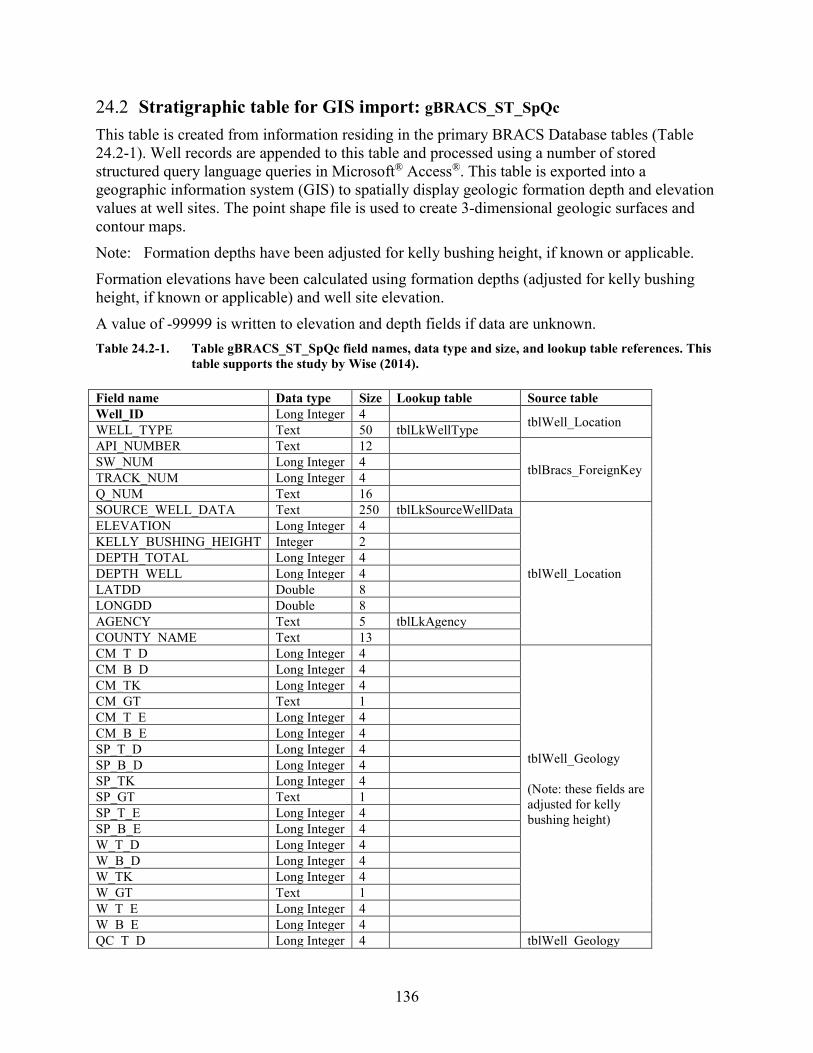
136
24.2 Stratigraphic table for GIS import: gBRACS_ST_SpQc This table is created from information residing in the primary BRACS Database tables (Table 24.2-1). Well records are appended to this table and processed using a number of stored structured query language queries in Microsoft® Access®. This table is exported into a geographic information system (GIS) to spatially display geologic formation depth and elevation values at well sites. The point shape file is used to create 3-dimensional geologic surfaces and contour maps. Note: Formation depths have been adjusted for kelly bushing height, if known or applicable. Formation elevations have been calculated using formation depths (adjusted for kelly bushing height, if known or applicable) and well site elevation. A value of -99999 is written to elevation and depth fields if data are unknown. Table 24.2-1. Table gBRACS_ST_SpQc field names, data type and size, and lookup table references. This
table supports the study by Wise (2014). Field name Data type Size Lookup table Source table Well_ID Long Integer 4 tblWell_Location WELL_TYPE Text 50 tblLkWellType API_NUMBER Text 12
tblBracs_ForeignKey SW_NUM Long Integer 4 TRACK_NUM Long Integer 4 Q_NUM Text 16 SOURCE_WELL_DATA Text 250 tblLkSourceWellData
tblWell_Location
ELEVATION Long Integer 4 KELLY_BUSHING_HEIGHT Integer 2 DEPTH_TOTAL Long Integer 4 DEPTH_WELL Long Integer 4 LATDD Double 8 LONGDD Double 8 AGENCY Text 5 tblLkAgency COUNTY_NAME Text 13 CM_T_D Long Integer 4
tblWell_Geology (Note: these fields are adjusted for kelly bushing height)
CM_B_D Long Integer 4 CM_TK Long Integer 4 CM_GT Text 1 CM_T_E Long Integer 4 CM_B_E Long Integer 4 SP_T_D Long Integer 4 SP_B_D Long Integer 4 SP_TK Long Integer 4 SP_GT Text 1 SP_T_E Long Integer 4 SP_B_E Long Integer 4 W_T_D Long Integer 4 W_B_D Long Integer 4 W_TK Long Integer 4 W_GT Text 1 W_T_E Long Integer 4 W_B_E Long Integer 4 QC_T_D Long Integer 4 tblWell_Geology
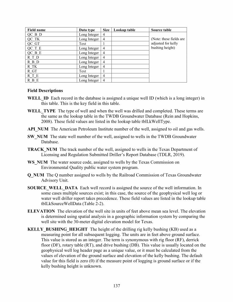
137
Field name Data type Size Lookup table Source table QC_B_D Long Integer 4
(Note: these fields are adjusted for kelly bushing height)
QC_TK Long Integer 4 QC_GT Text 1 QC_T_E Long Integer 4 QC_B_E Long Integer 4 R_T_D Long Integer 4 R_B_D Long Integer 4 R_TK Long Integer 4 R_GT Text 1 R_T_E Long Integer 4 R_B_E Long Integer 4 Field Descriptions WELL_ID Each record in the database is assigned a unique well ID (which is a long integer) in
this table. This is the key field in this table. WELL_TYPE The type of well and when the well was drilled and completed. These terms are
the same as the lookup table in the TWDB Groundwater Database (Rein and Hopkins, 2008). These field values are listed in the lookup table tblLkWellType.
API_NUM The American Petroleum Institute number of the well, assigned to oil and gas wells. SW_NUM The state well number of the well, assigned to wells in the TWDB Groundwater
Database. TRACK_NUM The track number of the well, assigned to wells in the Texas Department of
Licensing and Regulation Submitted Driller’s Report Database (TDLR, 2019). WS_NUM The water source code, assigned to wells by the Texas Commission on
Environmental Quality public water system program. Q_NUM The Q number assigned to wells by the Railroad Commission of Texas Groundwater
Advisory Unit. SOURCE_WELL_DATA Each well record is assigned the source of the well information. In
some cases multiple sources exist; in this case, the source of the geophysical well log or water well driller report takes precedence. These field values are listed in the lookup table tblLkSourceWellData (Table 2-2).
ELEVATION The elevation of the well site in units of feet above mean sea level. The elevation is determined using spatial analysis in a geographic information system by comparing the well site with the 30-meter digital elevation model for Texas.
KELLY_BUSHING_HEIGHT The height of the drilling rig kelly bushing (KB) used as a measuring point for all subsequent logging. The units are in feet above ground surface. This value is stored as an integer. The term is synonymous with rig floor (RF), derrick floor (DF), rotary table (RT), and drive bushing (DB). This value is usually located on the geophysical well log header page as a unique value, or it must be calculated from the values of elevation of the ground surface and elevation of the kelly bushing. The default value for this field is zero (0) if the measure point of logging is ground surface or if the kelly bushing height is unknown.

138
DEPTH_TOTAL The total depth of the hole in units of feet below ground surface. This is reported on the water well driller report or header page on a geophysical well log. A value of -99999 is used if the value is not known.
DEPTH_WELL The total depth of the well in units of feet below ground surface. This is reported on the water well driller report. A value of -99999 is used if the value is not known.
LATDD Latitude of the well site in units of decimal degrees. Latitude is a positive value, referring to a site north of the earth’s equator. Latitude and longitude coordinates are obtained from multiple sources. Latitude is obtained is based on a North American Datum of 1983.
LONGDD Longitude of the well site in units of decimal degrees. Longitude is a negative value, referring to a site west of the Prime Meridian in Greenwich, United Kingdom. Latitude and longitude coordinates are obtained from multiple sources. Longitude is based on a North American Datum of 1983.
AGENCY The agency that collected the latitude and longitude coordinates of the well site. These field values are listed in the lookup table tblLkAgency (Table 2-5).
J_T_D Jackson Group top depth in units of feet below ground surface. J_B_D Jackson Group bottom depth in units of feet below ground surface. J_TK Jackson Group thickness in units of feet. J_GT Greater than symbol (>) represents well only partially penetrates Jackson Group. J_T_E Jackson Group top elevation in units of feet above mean sea level. J_B_E Jackson Group bottom elevation in units of feet above mean sea level. Y_T_D Yegua Formation top depth in units of feet below ground surface. Y_B_D Yegua Formation bottom depth in units of feet below ground surface. Y_TK Yegua Formation thickness in units of feet. Y_GT Greater than symbol (>) represents well only partially penetrates Yegua Formation. Y_T_E Yegua Formation top elevation in units of feet above mean sea level. Y_B_E Yegua Formation bottom elevation in units of feet above mean sea level. CM_T_D Cook Mountain Formation top depth in units of feet below ground surface. CM_B_D Cook Mountain Formation bottom depth in units of feet below ground surface. CM_TK Cook Mountain Formation thickness in units of feet. CM_GT Greater than symbol (>) represents well only partially penetrates Cook Mountain
Formation. CM_T_E Cook Mountain Formation top elevation in units of feet above mean sea level. CM_B_E Cook Mountain Formation bottom elevation in units of feet above mean sea level. SP_T_D Sparta Formation top depth in units of feet below ground surface.
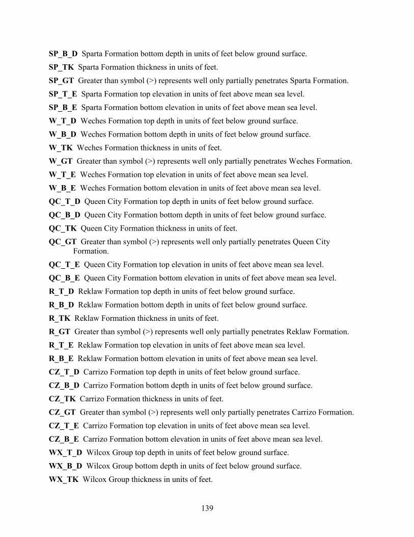
139
SP_B_D Sparta Formation bottom depth in units of feet below ground surface. SP_TK Sparta Formation thickness in units of feet. SP_GT Greater than symbol (>) represents well only partially penetrates Sparta Formation. SP_T_E Sparta Formation top elevation in units of feet above mean sea level. SP_B_E Sparta Formation bottom elevation in units of feet above mean sea level. W_T_D Weches Formation top depth in units of feet below ground surface. W_B_D Weches Formation bottom depth in units of feet below ground surface. W_TK Weches Formation thickness in units of feet. W_GT Greater than symbol (>) represents well only partially penetrates Weches Formation. W_T_E Weches Formation top elevation in units of feet above mean sea level. W_B_E Weches Formation bottom elevation in units of feet above mean sea level. QC_T_D Queen City Formation top depth in units of feet below ground surface. QC_B_D Queen City Formation bottom depth in units of feet below ground surface. QC_TK Queen City Formation thickness in units of feet. QC_GT Greater than symbol (>) represents well only partially penetrates Queen City
Formation. QC_T_E Queen City Formation top elevation in units of feet above mean sea level. QC_B_E Queen City Formation bottom elevation in units of feet above mean sea level. R_T_D Reklaw Formation top depth in units of feet below ground surface. R_B_D Reklaw Formation bottom depth in units of feet below ground surface. R_TK Reklaw Formation thickness in units of feet. R_GT Greater than symbol (>) represents well only partially penetrates Reklaw Formation. R_T_E Reklaw Formation top elevation in units of feet above mean sea level. R_B_E Reklaw Formation bottom elevation in units of feet above mean sea level. CZ_T_D Carrizo Formation top depth in units of feet below ground surface. CZ_B_D Carrizo Formation bottom depth in units of feet below ground surface. CZ_TK Carrizo Formation thickness in units of feet. CZ_GT Greater than symbol (>) represents well only partially penetrates Carrizo Formation. CZ_T_E Carrizo Formation top elevation in units of feet above mean sea level. CZ_B_E Carrizo Formation bottom elevation in units of feet above mean sea level. WX_T_D Wilcox Group top depth in units of feet below ground surface. WX_B_D Wilcox Group bottom depth in units of feet below ground surface. WX_TK Wilcox Group thickness in units of feet.
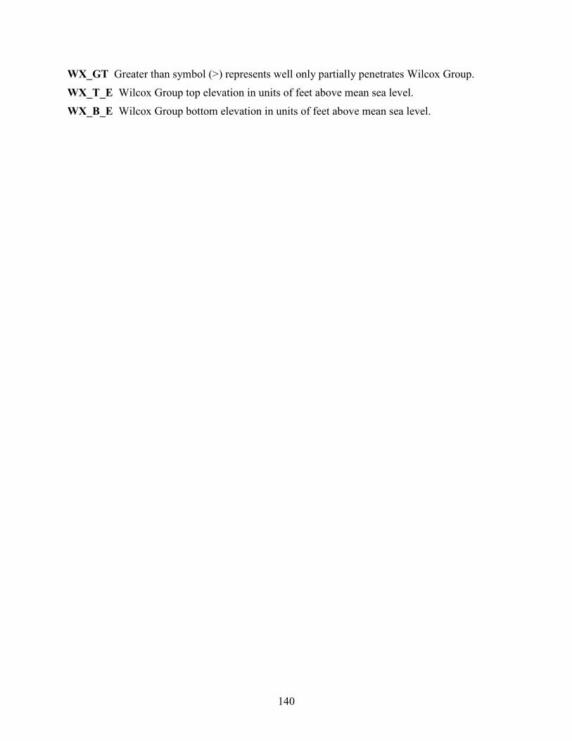
140
WX_GT Greater than symbol (>) represents well only partially penetrates Wilcox Group. WX_T_E Wilcox Group top elevation in units of feet above mean sea level. WX_B_E Wilcox Group bottom elevation in units of feet above mean sea level.
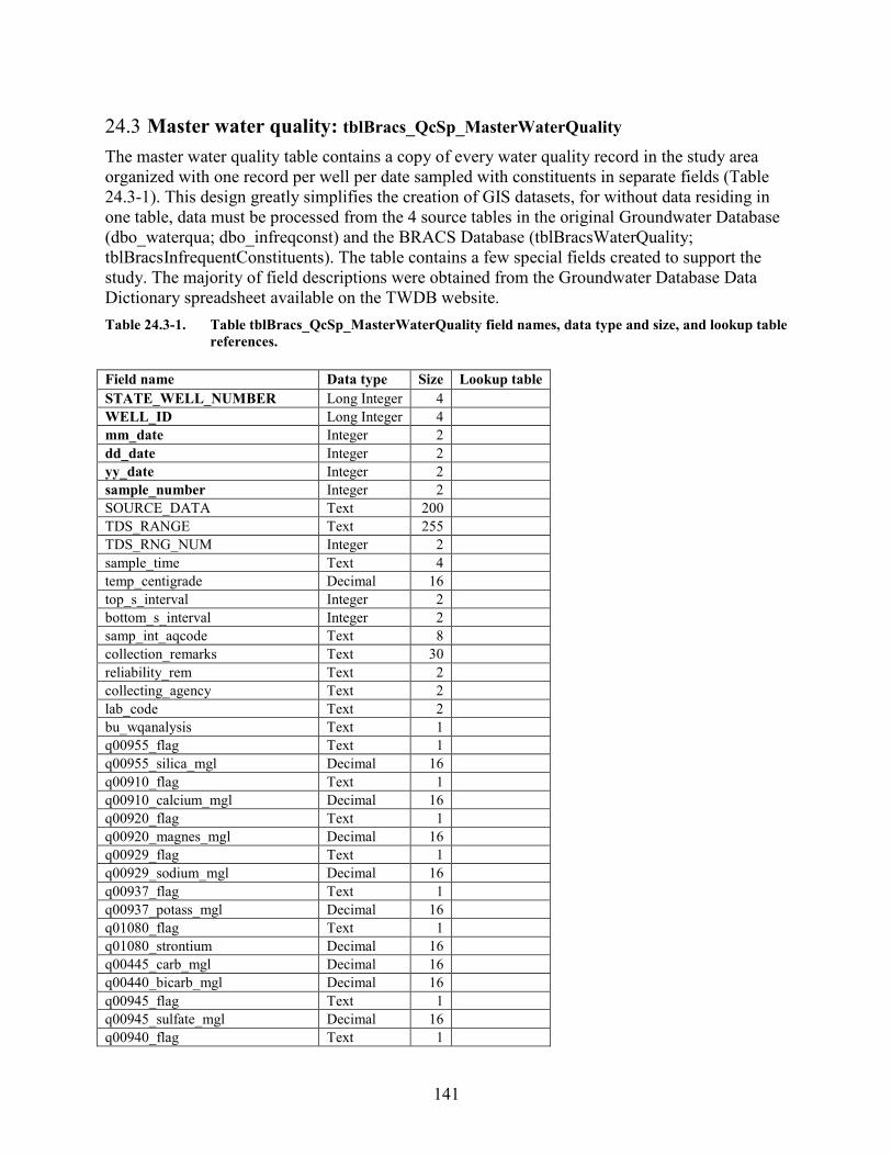
141
24.3 Master water quality: tblBracs_QcSp_MasterWaterQuality The master water quality table contains a copy of every water quality record in the study area organized with one record per well per date sampled with constituents in separate fields (Table 24.3-1). This design greatly simplifies the creation of GIS datasets, for without data residing in one table, data must be processed from the 4 source tables in the original Groundwater Database (dbo_waterqua; dbo_infreqconst) and the BRACS Database (tblBracsWaterQuality; tblBracsInfrequentConstituents). The table contains a few special fields created to support the study. The majority of field descriptions were obtained from the Groundwater Database Data Dictionary spreadsheet available on the TWDB website. Table 24.3-1. Table tblBracs_QcSp_MasterWaterQuality field names, data type and size, and lookup table
references. Field name Data type Size Lookup table STATE_WELL_NUMBER Long Integer 4
WELL_ID Long Integer 4
mm_date Integer 2
dd_date Integer 2
yy_date Integer 2
sample_number Integer 2
SOURCE_DATA Text 200
TDS_RANGE Text 255
TDS_RNG_NUM Integer 2
sample_time Text 4
temp_centigrade Decimal 16
top_s_interval Integer 2
bottom_s_interval Integer 2
samp_int_aqcode Text 8
collection_remarks Text 30
reliability_rem Text 2
collecting_agency Text 2
lab_code Text 2
bu_wqanalysis Text 1
q00955_flag Text 1
q00955_silica_mgl Decimal 16
q00910_flag Text 1
q00910_calcium_mgl Decimal 16
q00920_flag Text 1
q00920_magnes_mgl Decimal 16
q00929_flag Text 1
q00929_sodium_mgl Decimal 16
q00937_flag Text 1
q00937_potass_mgl Decimal 16
q01080_flag Text 1
q01080_strontium Decimal 16
q00445_carb_mgl Decimal 16
q00440_bicarb_mgl Decimal 16
q00945_flag Text 1
q00945_sulfate_mgl Decimal 16
q00940_flag Text 1
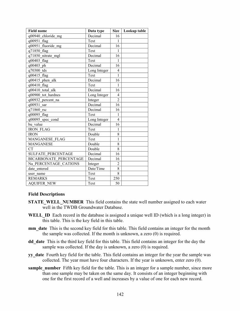
142
Field name Data type Size Lookup table q00940_chloride_mg Decimal 16
q00951_flag Text 1
q00951_fluoride_mg Decimal 16
q71850_flag Text 1
q71850_nitrate_mgl Decimal 16
q00403_flag Text 1
q00403_ph Decimal 16
q70300_tds Long Integer 4
q00415_flag Text 1
q00415_phen_alk Decimal 16
q00410_flag Text 1
q00410_total_alk Decimal 16
q00900_tot_hardnes Long Integer 4
q00932_percent_na Integer 2
q00931_sar Decimal 16
q71860_rsc Decimal 16
q00095_flag Text 1
q00095_spec_cond Long Integer 4
bu_value Decimal 16
IRON_FLAG Text 1
IRON Double 8
MANGANESE_FLAG Text 1
MANGANESE Double 8
CT Double 8
SULFATE_PERCENTAGE Decimal 16
BICARBONATE_PERCENTAGE Decimal 16
Na_PERCENTAGE_CATIONS Integer 2
date_entered Date/Time 8
user_name Text 8
REMARKS Text 250
AQUIFER_NEW Text 50 Field Descriptions STATE_WELL_NUMBER This field contains the state well number assigned to each water
well in the TWDB Groundwater Database. WELL_ID Each record in the database is assigned a unique well ID (which is a long integer) in
this table. This is the key field in this table. mm_date This is the second key field for this table. This field contains an integer for the month
the sample was collected. If the month is unknown, a zero (0) is required. dd_date This is the third key field for this table. This field contains an integer for the day the
sample was collected. If the day is unknown, a zero (0) is required. yy_date Fourth key field for the table. This field contains an integer for the year the sample was
collected. The year must have four characters. If the year is unknown, enter zero (0). sample_number Fifth key field for the table. This is an integer for a sample number, since more
than one sample may be taken on the same day. It consists of an integer beginning with one for the first record of a well and increases by a value of one for each new record.
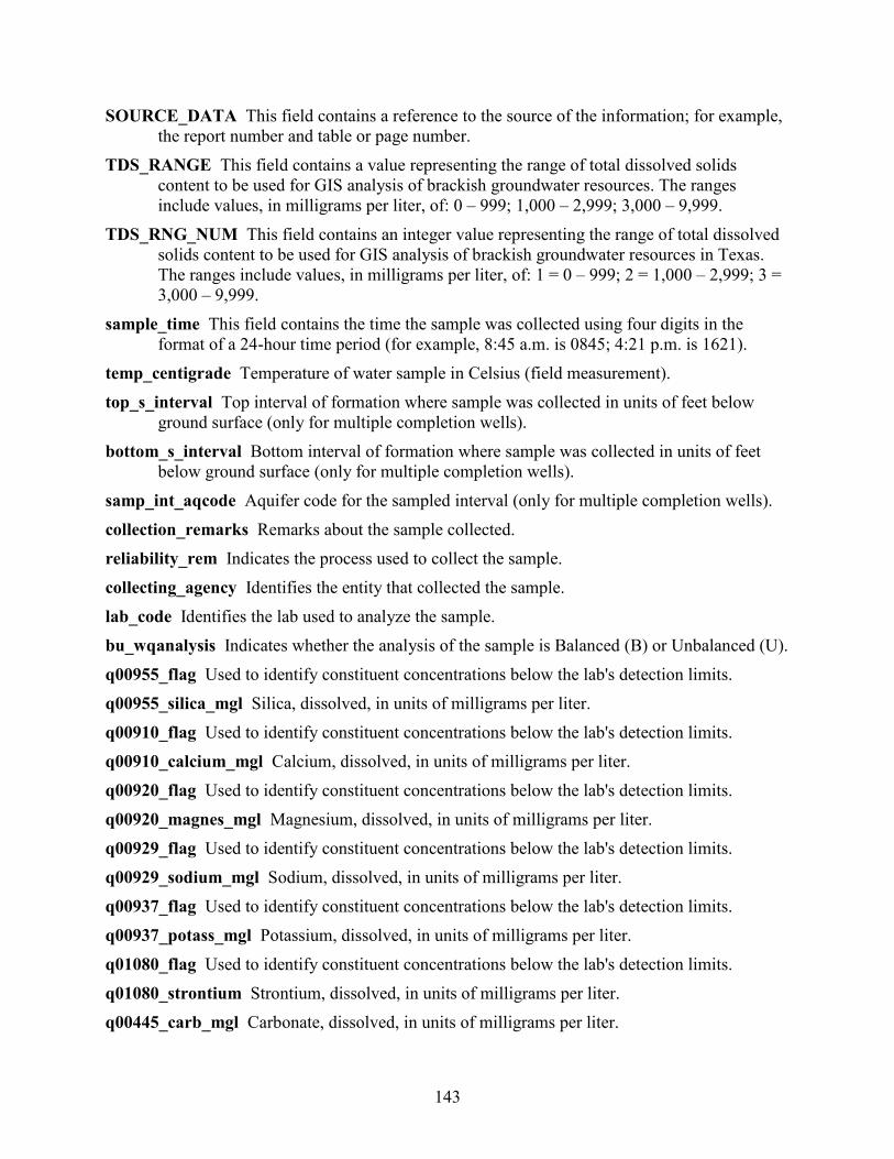
143
SOURCE_DATA This field contains a reference to the source of the information; for example, the report number and table or page number.
TDS_RANGE This field contains a value representing the range of total dissolved solids content to be used for GIS analysis of brackish groundwater resources. The ranges include values, in milligrams per liter, of: 0 – 999; 1,000 – 2,999; 3,000 – 9,999.
TDS_RNG_NUM This field contains an integer value representing the range of total dissolved solids content to be used for GIS analysis of brackish groundwater resources in Texas. The ranges include values, in milligrams per liter, of: 1 = 0 – 999; 2 = 1,000 – 2,999; 3 = 3,000 – 9,999.
sample_time This field contains the time the sample was collected using four digits in the format of a 24-hour time period (for example, 8:45 a.m. is 0845; 4:21 p.m. is 1621).
temp_centigrade Temperature of water sample in Celsius (field measurement). top_s_interval Top interval of formation where sample was collected in units of feet below
ground surface (only for multiple completion wells). bottom_s_interval Bottom interval of formation where sample was collected in units of feet
below ground surface (only for multiple completion wells). samp_int_aqcode Aquifer code for the sampled interval (only for multiple completion wells). collection_remarks Remarks about the sample collected. reliability_rem Indicates the process used to collect the sample. collecting_agency Identifies the entity that collected the sample. lab_code Identifies the lab used to analyze the sample. bu_wqanalysis Indicates whether the analysis of the sample is Balanced (B) or Unbalanced (U). q00955_flag Used to identify constituent concentrations below the lab's detection limits. q00955_silica_mgl Silica, dissolved, in units of milligrams per liter. q00910_flag Used to identify constituent concentrations below the lab's detection limits. q00910_calcium_mgl Calcium, dissolved, in units of milligrams per liter. q00920_flag Used to identify constituent concentrations below the lab's detection limits. q00920_magnes_mgl Magnesium, dissolved, in units of milligrams per liter. q00929_flag Used to identify constituent concentrations below the lab's detection limits. q00929_sodium_mgl Sodium, dissolved, in units of milligrams per liter. q00937_flag Used to identify constituent concentrations below the lab's detection limits. q00937_potass_mgl Potassium, dissolved, in units of milligrams per liter. q01080_flag Used to identify constituent concentrations below the lab's detection limits. q01080_strontium Strontium, dissolved, in units of milligrams per liter. q00445_carb_mgl Carbonate, dissolved, in units of milligrams per liter.
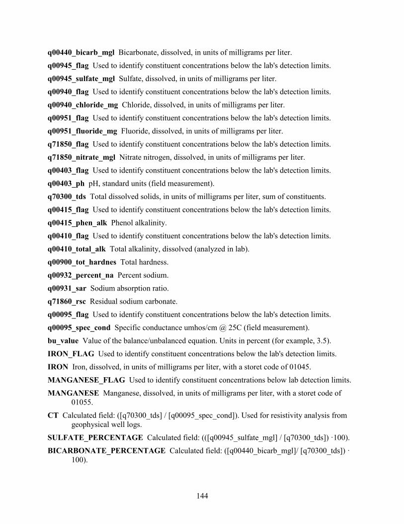
144
q00440_bicarb_mgl Bicarbonate, dissolved, in units of milligrams per liter. q00945_flag Used to identify constituent concentrations below the lab's detection limits. q00945_sulfate_mgl Sulfate, dissolved, in units of milligrams per liter. q00940_flag Used to identify constituent concentrations below the lab's detection limits. q00940_chloride_mg Chloride, dissolved, in units of milligrams per liter. q00951_flag Used to identify constituent concentrations below the lab's detection limits. q00951_fluoride_mg Fluoride, dissolved, in units of milligrams per liter. q71850_flag Used to identify constituent concentrations below the lab's detection limits. q71850_nitrate_mgl Nitrate nitrogen, dissolved, in units of milligrams per liter. q00403_flag Used to identify constituent concentrations below the lab's detection limits. q00403_ph pH, standard units (field measurement). q70300_tds Total dissolved solids, in units of milligrams per liter, sum of constituents. q00415_flag Used to identify constituent concentrations below the lab's detection limits. q00415_phen_alk Phenol alkalinity. q00410_flag Used to identify constituent concentrations below the lab's detection limits. q00410_total_alk Total alkalinity, dissolved (analyzed in lab). q00900_tot_hardnes Total hardness. q00932_percent_na Percent sodium. q00931_sar Sodium absorption ratio. q71860_rsc Residual sodium carbonate. q00095_flag Used to identify constituent concentrations below the lab's detection limits. q00095_spec_cond Specific conductance umhos/cm @ 25C (field measurement). bu_value Value of the balance/unbalanced equation. Units in percent (for example, 3.5). IRON_FLAG Used to identify constituent concentrations below the lab's detection limits. IRON Iron, dissolved, in units of milligrams per liter, with a storet code of 01045. MANGANESE_FLAG Used to identify constituent concentrations below lab detection limits. MANGANESE Manganese, dissolved, in units of milligrams per liter, with a storet code of
01055. CT Calculated field: ([q70300_tds] / [q00095_spec_cond]). Used for resistivity analysis from
geophysical well logs. SULFATE_PERCENTAGE Calculated field: (([q00945_sulfate_mgl] / [q70300_tds]) ·100). BICARBONATE_PERCENTAGE Calculated field: ([q00440_bicarb_mgl]/ [q70300_tds]) ·
100).
145
Na_PERCENTAGE_CATIONS Calculated field: (([q00929_sodium_mgl] / ([q00929_sodium_mgl] + [q00910_calcium_mgl] + [q00920_magnes_mgl] + [q00937_potass_mgl])) · 100).
date_entered This field contains the date the record was last edited. user_name User name of person who last edited the record. REMARKS General remarks about an analysis. AQUIFER_NEW Field containing code for the new aquifer assignment. These field values are
listed in the lookup table tblLkBRACSAquifer_AD (Table 24.1-3). The table was created because not all aquifer combinations are available in the Groundwater Database aquifer code table.
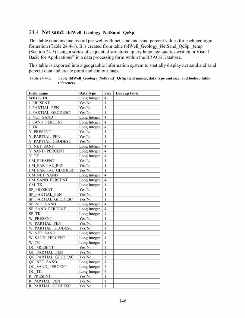
146
24.4 Net sand: tblWell_Geology_NetSand_QcSp This table contains one record per well with net sand and sand percent values for each geologic formation (Table 24.4-1). It is created from table tblWell_Geology_NetSand_QcSp _temp (Section 24.5) using a series of sequential structured query language queries written in Visual Basic for Applications® in a data processing form within the BRACS Database. This table is exported into a geographic information system to spatially display net sand and sand percent data and create point and contour maps. Table 24.4-1. Table tblWell_Geology_NetSand_ QcSp field names, data type and size, and lookup table
references. Field name Data type Size Lookup table WELL_ID Long Integer 4 J_PRESENT Yes/No 1 J_PARTIAL_PEN Yes/No 1 J_PARTIAL_GEODESC Yes/No 1 J_NET_SAND Long Integer 4 J_SAND_PERCENT Long Integer 4 J_TK Long Integer 4 Y_PRESENT Yes/No 1 Y_PARTIAL_PEN Yes/No 1 Y_PARTIAL_GEODESC Yes/No 1 Y_NET_SAND Long Integer 4 Y_SAND_PERCENT Long Integer 4 Y_TK Long Integer 4 CM_PRESENT Yes/No 1 CM_PARTIAL_PEN Yes/No 1 CM_PARTIAL_GEODESC Yes/No 1 CM_NET_SAND Long Integer 4 CM_SAND_PERCENT Long Integer 4 CM_TK Long Integer 4 SP_PRESENT Yes/No 1 SP_PARTIAL_PEN Yes/No 1 SP_PARTIAL_GEODESC Yes/No 1 SP_NET_SAND Long Integer 4 SP_SAND_PERCENT Long Integer 4 SP_TK Long Integer 4 W_PRESENT Yes/No 1 W_PARTIAL_PEN Yes/No 1 W_PARTIAL_GEODESC Yes/No 1 W_NET_SAND Long Integer 4 W_SAND_PERCENT Long Integer 4 W_TK Long Integer 4 QC_PRESENT Yes/No 1 QC_PARTIAL_PEN Yes/No 1 QC_PARTIAL_GEODESC Yes/No 1 QC_NET_SAND Long Integer 4 QC_SAND_PERCENT Long Integer 4 QC_TK Long Integer 4 R_PRESENT Yes/No 1 R_PARTIAL_PEN Yes/No 1 R_PARTIAL_GEODESC Yes/No 1
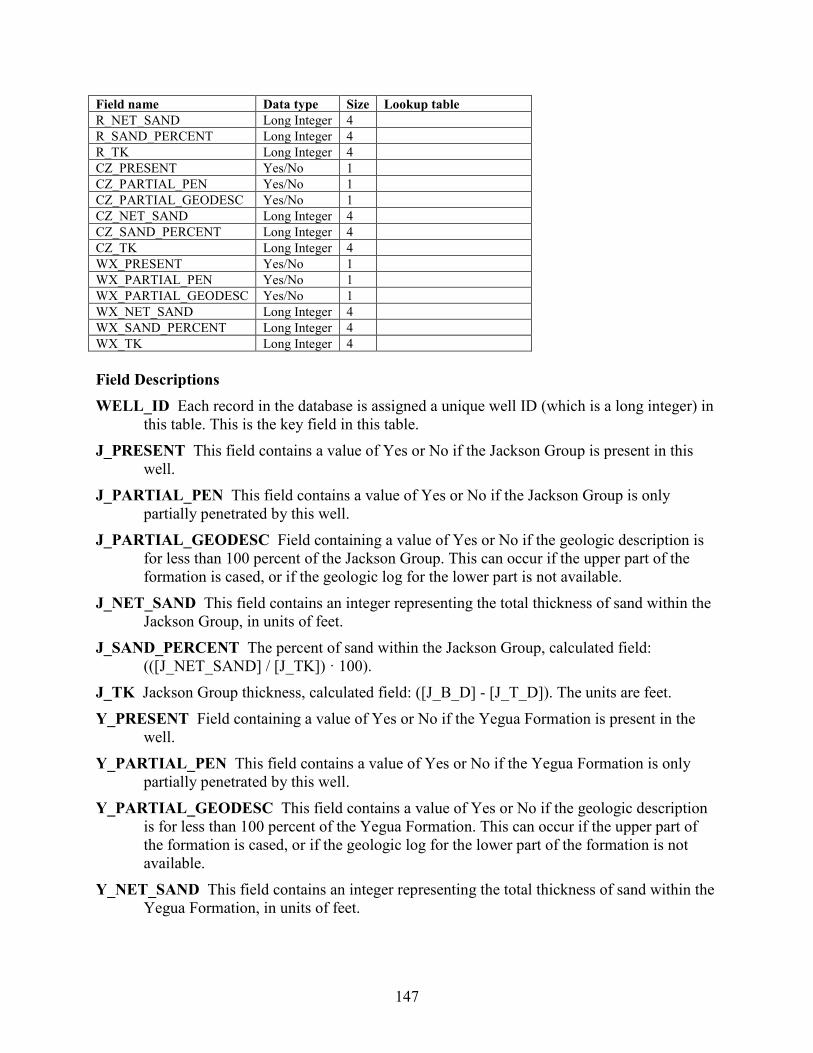
147
Field name Data type Size Lookup table R_NET_SAND Long Integer 4 R_SAND_PERCENT Long Integer 4 R_TK Long Integer 4 CZ_PRESENT Yes/No 1 CZ_PARTIAL_PEN Yes/No 1 CZ_PARTIAL_GEODESC Yes/No 1 CZ_NET_SAND Long Integer 4 CZ_SAND_PERCENT Long Integer 4 CZ_TK Long Integer 4 WX_PRESENT Yes/No 1 WX_PARTIAL_PEN Yes/No 1 WX_PARTIAL_GEODESC Yes/No 1 WX_NET_SAND Long Integer 4 WX_SAND_PERCENT Long Integer 4 WX_TK Long Integer 4 Field Descriptions WELL_ID Each record in the database is assigned a unique well ID (which is a long integer) in
this table. This is the key field in this table. J_PRESENT This field contains a value of Yes or No if the Jackson Group is present in this
well. J_PARTIAL_PEN This field contains a value of Yes or No if the Jackson Group is only
partially penetrated by this well. J_PARTIAL_GEODESC Field containing a value of Yes or No if the geologic description is
for less than 100 percent of the Jackson Group. This can occur if the upper part of the formation is cased, or if the geologic log for the lower part is not available.
J_NET_SAND This field contains an integer representing the total thickness of sand within the Jackson Group, in units of feet.
J_SAND_PERCENT The percent of sand within the Jackson Group, calculated field: (([J_NET_SAND] / [J_TK]) · 100).
J_TK Jackson Group thickness, calculated field: ([J_B_D] - [J_T_D]). The units are feet. Y_PRESENT Field containing a value of Yes or No if the Yegua Formation is present in the
well. Y_PARTIAL_PEN This field contains a value of Yes or No if the Yegua Formation is only
partially penetrated by this well. Y_PARTIAL_GEODESC This field contains a value of Yes or No if the geologic description
is for less than 100 percent of the Yegua Formation. This can occur if the upper part of the formation is cased, or if the geologic log for the lower part of the formation is not available.
Y_NET_SAND This field contains an integer representing the total thickness of sand within the Yegua Formation, in units of feet.
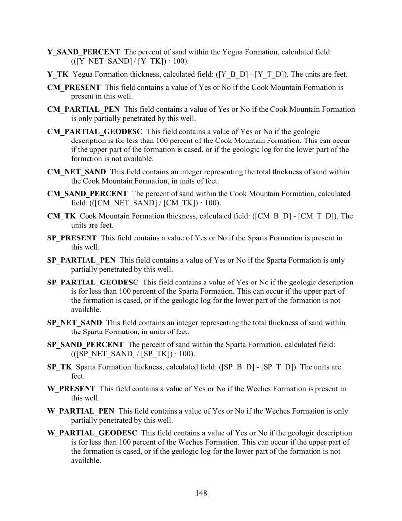
148
Y_SAND_PERCENT The percent of sand within the Yegua Formation, calculated field: (([Y_NET_SAND] / [Y_TK]) · 100).
Y_TK Yegua Formation thickness, calculated field: ([Y_B_D] - [Y_T_D]). The units are feet. CM_PRESENT This field contains a value of Yes or No if the Cook Mountain Formation is
present in this well. CM_PARTIAL_PEN This field contains a value of Yes or No if the Cook Mountain Formation
is only partially penetrated by this well. CM_PARTIAL_GEODESC This field contains a value of Yes or No if the geologic
description is for less than 100 percent of the Cook Mountain Formation. This can occur if the upper part of the formation is cased, or if the geologic log for the lower part of the formation is not available.
CM_NET_SAND This field contains an integer representing the total thickness of sand within the Cook Mountain Formation, in units of feet.
CM_SAND_PERCENT The percent of sand within the Cook Mountain Formation, calculated field: (([CM_NET_SAND] / [CM_TK]) · 100).
CM_TK Cook Mountain Formation thickness, calculated field: ([CM_B_D] - [CM_T_D]). The units are feet.
SP_PRESENT This field contains a value of Yes or No if the Sparta Formation is present in this well.
SP_PARTIAL_PEN This field contains a value of Yes or No if the Sparta Formation is only partially penetrated by this well.
SP_PARTIAL_GEODESC This field contains a value of Yes or No if the geologic description is for less than 100 percent of the Sparta Formation. This can occur if the upper part of the formation is cased, or if the geologic log for the lower part of the formation is not available.
SP_NET_SAND This field contains an integer representing the total thickness of sand within the Sparta Formation, in units of feet.
SP_SAND_PERCENT The percent of sand within the Sparta Formation, calculated field: (([SP_NET_SAND] / [SP_TK]) · 100).
SP_TK Sparta Formation thickness, calculated field: ([SP_B_D] - [SP_T_D]). The units are feet.
W_PRESENT This field contains a value of Yes or No if the Weches Formation is present in this well.
W_PARTIAL_PEN This field contains a value of Yes or No if the Weches Formation is only partially penetrated by this well.
W_PARTIAL_GEODESC This field contains a value of Yes or No if the geologic description is for less than 100 percent of the Weches Formation. This can occur if the upper part of the formation is cased, or if the geologic log for the lower part of the formation is not available.
149
W_NET_SAND This field contains an integer representing the total thickness of sand within the Weches Formation, in units of feet.
W_SAND_PERCENT The percent of sand within the Weches Formation, calculated field: (([W_NET_SAND] / [W_TK]) · 100).
W_TK Weches Formation thickness, calculated field: ([W_B_D] - [W_T_D]). The units are feet.
QC_PRESENT This field contains a value of Yes or No if the Queen City Formation is present in this well.
QC_PARTIAL_PEN This field contains a value of Yes or No if the Queen City Formation is only partially penetrated by this well.
QC_PARTIAL_GEODESC This field contains a value of Yes or No if the geologic description is for less than 100 percent of the Queen City Formation. This can occur if the upper part of the formation is cased, or if the geologic log for the lower part of the formation is not available.
QC_NET_SAND This field contains an integer representing the total thickness of sand within the Queen City Formation, in units of feet.
QC_SAND_PERCENT The percent of sand within the Queen City Formation, calculated field: (([QC_NET_SAND] / [QC_TK]) · 100).
QC_TK Queen City Formation thickness, calculated field: ([QC_B_D] - [QC_T_D]). The units are feet.
R_PRESENT Field containing a value of Yes or No if Reklaw Formation is present in the well. R_PARTIAL_PEN This field contains a value of Yes or No if the Reklaw Formation is only
partially penetrated by this well. R_PARTIAL_GEODESC This field contains a value of Yes or No if the geologic description
is for less than 100 percent of the Reklaw Formation. This can occur if the upper part of the formation is cased, or if the geologic log for the lower part of the formation is not available.
R_NET_SAND This field contains an integer representing the total thickness of sand within the Reklaw Formation, in units of feet.
R_SAND_PERCENT The percent of sand within the Reklaw Formation, calculated field: (([R_NET_SAND] / [R_TK]) · 100).
R_TK Reklaw Formation thickness, calculated field: ([R_B_D] - [R_T_D]). The units are feet. CZ_PRESENT This field contains a value of Yes or No if the Carrizo Formation is present in
this well. CZ_PARTIAL_PEN This field contains a value of Yes or No if the Carrizo Formation is only
partially penetrated by this well. CZ_PARTIAL_GEODESC This field contains a value of Yes or No if the geologic description
is for less than 100 percent of the Carrizo Formation. This can occur if the upper part of
150
the formation is cased, or if the geologic log for the lower part of the formation is not available.
CZ_NET_SAND This field contains an integer representing the total thickness of sand within the Carrizo Formation, in units of feet.
CZ_SAND_PERCENT The percent of sand within the Carrizo Formation, calculated field: (([CZ_NET_SAND] / [CZ_TK]) · 100).
CZ_TK Carrizo Formation thickness, calculated field: ([CZ_B_D] - [CZ_T_D]). The units are feet.
WX_PRESENT This field contains a value of Yes or No if the Wilcox Group is present in this well.
WX_PARTIAL_PEN This field contains a value of Yes or No if the Wilcox Group is only partially penetrated by this well.
WX_PARTIAL_GEODESC This field contains a value of Yes or No if the geologic description is for less than 100 percent of the Wilcox Group. This can occur if the upper part of the formation is cased, or if the geologic log for the lower part of the formation is not available.
WX_NET_SAND This field contains an integer representing the total thickness of sand within the Wilcox Group, in units of feet.
WX_SAND_PERCENT The percent of sand within the Wilcox Group, calculated field: (([WX_NET_SAND] / [WX_TK]) · 100).
WX_TK Wilcox Group thickness, calculated field: ([WX_B_D] - [WX_T_D]). The units are feet.

151
24.5 Net sand: tblWell_Geology_NetSand_QcSp_Temp This table was created to support the processing of net sand and sand percent data for wells in the study area. This table will contain one or more records per well if the lithologic description for any record contains reference to sand or gravel. This table is created from information residing in tables: tblWell_Geology; tblLkLithologicName_to_SimplifiedLithologicName; and tblAquiferDetermination_PaleoceneEocene_sTx_QcSp (Table 24.5-1). These records are then processed using a number of stored queries and loaded into the table tblWell_Geology_NetSand_QcSp. The value of maintaining this table is that special sand maps can be developed. For example, maximum sand unit thickness per formation, number of sands units greater than some value (for example, 50 feet) per formation, number of and cumulative thickness of sands within a specific depth range, and so on. Table 24.5-1. Table tblWell_Geology_NetSand_QcSp_Temp field names, data type and size, and lookup
table references. Field name Data type Size Lookup table WELL_ID Long Integer 4 RECORD_NUMBER Integer 2 SOURCE_GEOLOGIC_DATA Text 50 tblLkSourceGeologicData LITHOLOGIC_NAME Text 100 SIMPLIFIED_LITHOLOGIC_NAME Text 100 tblLkSimplified_Lithologic_Name SAND_PERCENT Decimal 16 DEPTH_TOP Single 4 DEPTH_BOTTOM Single 4 THICKNESS Single 4 J_T_D Long Integer 4 J_B_D Long Integer 4 J_FM Text 10 tblLkSandPositionCode J_NS_TK Integer 2 Y_T_D Long Integer 4 Y_B_D Long Integer 4 Y_FM Text 10 tblLkSandPositionCode Y_NS_TK Integer 2 CM_T_D Long Integer 4 CM_B_D Long Integer 4 CM_FM Text 10 tblLkSandPositionCode CM_NS_TK Integer 2 SP_T_D Long Integer 4 SP_B_D Long Integer 4 SP_FM Text 10 tblLkSandPositionCode SP_NS_TK Integer 2 W_T_D Long Integer 4 W_B_D Long Integer 4 W_FM Text 10 tblLkSandPositionCode W_NS_TK Integer 2 QC_T_D Long Integer 4 QC_B_D Long Integer 4 QC_FM Text 10 tblLkSandPositionCode QC_NS_TK Integer 2 R_T_D Long Integer 4
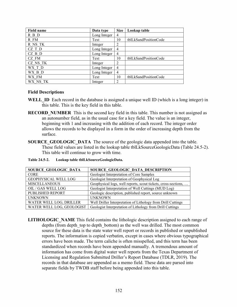
152
Field name Data type Size Lookup table R_B_D Long Integer 4 R_FM Text 10 tblLkSandPositionCode R_NS_TK Integer 2 CZ_T_D Long Integer 4 CZ_B_D Long Integer 4 CZ_FM Text 10 tblLkSandPositionCode CZ_NS_TK Integer 2 WX_T_D Long Integer 4 WX_B_D Long Integer 4 WX_FM Text 10 tblLkSandPositionCode WX_NS_TK Integer 2 Field Descriptions WELL_ID Each record in the database is assigned a unique well ID (which is a long integer) in
this table. This is the key field in this table. RECORD_NUMBER This is the second key field in this table. This number is not assigned as
an autonumber field, as in the usual case for a key field. The value is an integer, beginning with 1 and increasing with the addition of each record. The integer order allows the records to be displayed in a form in the order of increasing depth from the surface.
SOURCE_GEOLOGIC_DATA The source of the geologic data appended into the table. These field values are listed in the lookup table tblLkSourceGeologicData (Table 24.5-2). This table will continue to grow with time.
Table 24.5-2. Lookup table tblLkSourceGeologicData. SOURCE_GEOLOGIC_DATA SOURCE_GEOLOGIC_DATA_DESCRIPTION CORE Geologist Interpretation of Core Samples GEOPHYSICAL WELL LOG Geologist Interpretation of Geophysical Log MISCELLANEOUS Geophysical logs, well reports, scout tickets, cross-sections, … OIL / GAS WELL LOG Geologist Interpretation of Well Cuttings (MUD Log) PUBLISHED REPORT Geologic description, published report, source unknown UNKNOWN UNKNOWN WATER WELL LOG, DRILLER Well Driller Interpretation of Lithology from Drill Cuttings WATER WELL LOG, GEOLOGIST Geologist Interpretation of Lithology from Drill Cuttings LITHOLOGIC_NAME This field contains the lithologic description assigned to each range of
depths (from depth_top to depth_bottom) as the well was drilled. The most common source for these data is the state water well report or records in published or unpublished reports. The information is copied verbatim, except in cases where obvious typographical errors have been made. The term caliche is often misspelled, and this term has been standardized when records have been appended manually. A tremendous amount of information has come from digital water well reports from the Texas Department of Licensing and Regulation Submitted Driller’s Report Database (TDLR, 2019). The records in that database are appended as a memo field. These data are parsed into separate fields by TWDB staff before being appended into this table.
153
SIMPLIFIED_LITHOLOGIC_NAME This field contains a simplified version of the lithologic description so additional automated processing can be accomplished. For example, a unit consisting of sand may be written in over 250 different forms on water well reports. The lookup table tblLkLithologicName_to_SimplifiedLithologicName was created to relate the two fields. A query was written to automatically update this simplified_lithologic_name field from the lithologic_name field using values in the lookup table. The lookup table will grow with time as new records are appended to the table.
SAND_PERCENT The percent sand associated with this record. This value is associated with the definition of each record in the lookup table tblLkSimplified_Lithologic_Name.
DEPTH_TOP This field contains the depth to the top of the unit (referred to by the geologic pick field) in the units of feet below ground surface. The value is always a positive integer. This field is corrected for kelly bushing height.
DEPTH_BOTTOM This field contains the depth to the bottom of the unit (referred to by the geologic pick field) in the units of feet below ground surface. The value is always a positive integer. This field is corrected for kelly bushing height.
THICKNESS This is a calculated field: ([depth_bottom] – [depth_top]). The units are feet. J_T_D Jackson Group top depth in units of feet below ground surface. J_B_D Jackson Group bottom depth in units of feet below ground surface. J_FM Relationship of the lithologic top and bottom (fields [depth_top] and [depth_bottom]) to
Jackson Group top and bottom (fields [J_T_D] and [J_B_D]). These field values are listed in the lookup table tblLkSandPositionCode (Table 24.5-3).
Table 24.5-3. Lookup table tblLkSandPositionCode. SAND_POSITION_CODE CODE_DESCRIPTION W Sand is completely within formation ST Sand straddles top of formation SB Sand straddles bottom of formation SS Sand straddles top and bottom of formation X Sand not in formation
J_NS_TK Corrected net sand thickness of the Jackson Group, per individual lithologic unit, in units of feet.
Y_T_D Yegua Formation top depth in units of feet below ground surface. Y_B_D Yegua Formation bottom depth in units of feet below ground surface. Y_FM Relationship of the lithologic top and bottom (fields [depth_top] and [depth_bottom]) to
Yegua Formation top and bottom (fields [Y_T_D] and [Y_B_D]). These field values are listed in the lookup table tblLkSandPositionCode (Table 24.5-3).
Y_NS_TK Corrected net sand thickness of the Yegua Formation, per individual lithologic unit, in units of feet.
CM_T_D Cook Mountain Formation top depth in units of feet below ground surface. CM_B_D Cook Mountain Formation bottom depth in units of feet below ground surface.
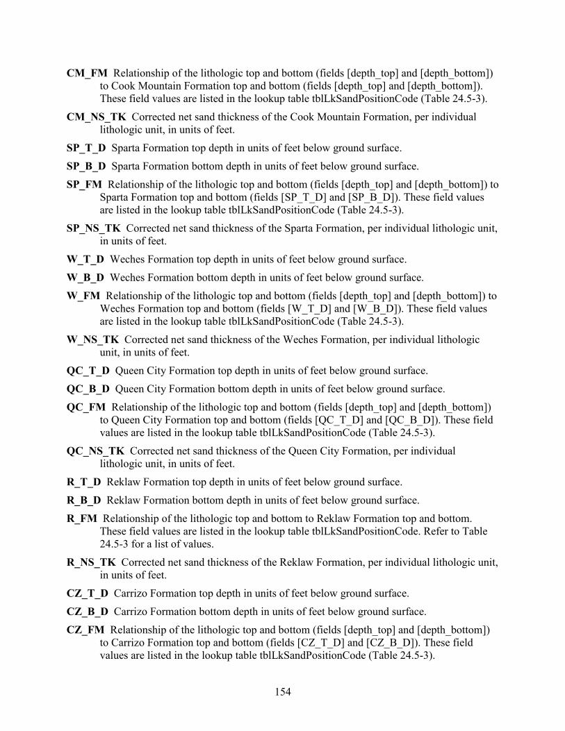
154
CM_FM Relationship of the lithologic top and bottom (fields [depth_top] and [depth_bottom]) to Cook Mountain Formation top and bottom (fields [depth_top] and [depth_bottom]). These field values are listed in the lookup table tblLkSandPositionCode (Table 24.5-3).
CM_NS_TK Corrected net sand thickness of the Cook Mountain Formation, per individual lithologic unit, in units of feet.
SP_T_D Sparta Formation top depth in units of feet below ground surface. SP_B_D Sparta Formation bottom depth in units of feet below ground surface. SP_FM Relationship of the lithologic top and bottom (fields [depth_top] and [depth_bottom]) to
Sparta Formation top and bottom (fields [SP_T_D] and [SP_B_D]). These field values are listed in the lookup table tblLkSandPositionCode (Table 24.5-3).
SP_NS_TK Corrected net sand thickness of the Sparta Formation, per individual lithologic unit, in units of feet.
W_T_D Weches Formation top depth in units of feet below ground surface. W_B_D Weches Formation bottom depth in units of feet below ground surface. W_FM Relationship of the lithologic top and bottom (fields [depth_top] and [depth_bottom]) to
Weches Formation top and bottom (fields [W_T_D] and [W_B_D]). These field values are listed in the lookup table tblLkSandPositionCode (Table 24.5-3).
W_NS_TK Corrected net sand thickness of the Weches Formation, per individual lithologic unit, in units of feet.
QC_T_D Queen City Formation top depth in units of feet below ground surface. QC_B_D Queen City Formation bottom depth in units of feet below ground surface. QC_FM Relationship of the lithologic top and bottom (fields [depth_top] and [depth_bottom])
to Queen City Formation top and bottom (fields [QC_T_D] and [QC_B_D]). These field values are listed in the lookup table tblLkSandPositionCode (Table 24.5-3).
QC_NS_TK Corrected net sand thickness of the Queen City Formation, per individual lithologic unit, in units of feet.
R_T_D Reklaw Formation top depth in units of feet below ground surface. R_B_D Reklaw Formation bottom depth in units of feet below ground surface. R_FM Relationship of the lithologic top and bottom to Reklaw Formation top and bottom.
These field values are listed in the lookup table tblLkSandPositionCode. Refer to Table 24.5-3 for a list of values.
R_NS_TK Corrected net sand thickness of the Reklaw Formation, per individual lithologic unit, in units of feet.
CZ_T_D Carrizo Formation top depth in units of feet below ground surface. CZ_B_D Carrizo Formation bottom depth in units of feet below ground surface. CZ_FM Relationship of the lithologic top and bottom (fields [depth_top] and [depth_bottom])
to Carrizo Formation top and bottom (fields [CZ_T_D] and [CZ_B_D]). These field values are listed in the lookup table tblLkSandPositionCode (Table 24.5-3).
155
CZ_NS_TK Corrected net sand thickness of the Carrizo Formation, per individual lithologic unit, in units of feet.
WX_T_D Wilcox Group top depth in units of feet below ground surface. WX_B_D Wilcox Group bottom depth in units of feet below ground surface. WX_FM Relationship of the lithologic top and bottom (fields [depth_top] and [depth_bottom])
to Wilcox Group top and bottom (fields [WX_T_D] and [WX_B_D]). These field values are listed in the lookup table tblLkSandPositionCode (Table 24.5-3).
WX_NS_TK Corrected net sand thickness of the Wilcox Group, per individual lithologic unit, in units of feet.
156
25. Appendix E: Wilcox, Carrizo, Queen City, Sparta, and Yegua Aquifers
The tables in this appendix were developed for the following Texas Water Development Board BRACS study: Meyer, J. E., Croskrey, A.D., Suydam, A.K , and Van Oort, N., 2019, Brackish groundwater in
aquifers of the Upper Coastal Plains, Central Texas: Structure and brackish groundwater: Texas Water Development Board Report, in progress
25.1 Aquifer determination: tblAquiferDetermination_PaleoceneEocene_sTx This table contains information on which aquifer(s) may be used or penetrated by a well in the study area (Table 25.1-1). Although aquifer codes have been assigned to wells in the Groundwater Database (TWDB, 2019b), it was determined that a systematic assessment of every well in the study area using the 3-dimensional formation top and bottom surfaces with available well screen and well depth data would provide a more accurate and uniform aquifer assignment. Using the new aquifer codes, wells with water quality data could be compared to wells using the same aquifer. The GIS raster surfaces were prepared using the well site elevation of the geologic formation, correction points, and interpolation software. The well site elevation of the geologic formation was then “burned in” to the grid cell. The depth rasters were created from the elevation rasters using the study grid cell elevation file. This process is explained in greater detail in the study report. Every well within the limits of the study area that is in the BRACS Database (TWDB, 2019a) and the Groundwater Database (TWDB, 2019b) was appended to a holding table. This information was imported and geo-referenced in a geographic information system (GIS). The top and bottom of each geological formation of interest was determined at each well location and the values were written to the holding table. For this study, the geologic formations include the Wilcox Group, Carrizo Formation, Reklaw Formation, Queen City Formation, Weches Formation, Sparta Formation, Cook Mountain Formation, and Yegua Formation. The stratigraphic sequence of geologic formations vary across the study area, so regions were mapped (Table 25.1-2) with similar stratigraphy and an integer value representing each region was assigned to every well to support subsequent analysis. Values for the shallowest and deepest screen depths, well depths, and total depth of hole were obtained from TWDB BRACS and Groundwater Database tables. A series of stored queries in Microsoft® Access® was used to determine if a well screen intersected a particular formation. A well may be screened in one or more aquifers. If well screen information was not available, well depth or total depth of hole were used to determine potential aquifers that were penetrated. The procedures used to process all of this information are documented in a TWDB work process document. A value of -99999 is written to elevation and depth fields if data are unknown.
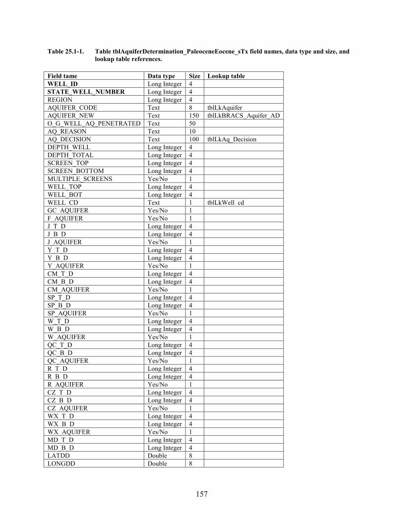
157
Table 25.1-1. Table tblAquiferDetermination_PaleoceneEocene_sTx field names, data type and size, and lookup table references.
Field tame Data type Size Lookup table WELL_ID Long Integer 4 STATE_WELL_NUMBER Long Integer 4 REGION Long Integer 4 AQUIFER_CODE Text 8 tblLkAquifer AQUIFER_NEW Text 150 tblLkBRACS_Aquifer_AD O_G_WELL_AQ_PENETRATED Text 50 AQ_REASON Text 10 AQ_DECISION Text 100 tblLkAq_Decision DEPTH_WELL Long Integer 4 DEPTH_TOTAL Long Integer 4 SCREEN_TOP Long Integer 4 SCREEN_BOTTOM Long Integer 4 MULTIPLE_SCREENS Yes/No 1 WELL_TOP Long Integer 4 WELL_BOT Long Integer 4 WELL_CD Text 1 tblLkWell_cd GC_AQUIFER Yes/No 1 F_AQUIFER Yes/No 1 J_T_D Long Integer 4 J_B_D Long Integer 4 J_AQUIFER Yes/No 1 Y_T_D Long Integer 4 Y_B_D Long Integer 4 Y_AQUIFER Yes/No 1 CM_T_D Long Integer 4 CM_B_D Long Integer 4 CM_AQUIFER Yes/No 1 SP_T_D Long Integer 4 SP_B_D Long Integer 4 SP_AQUIFER Yes/No 1 W_T_D Long Integer 4 W_B_D Long Integer 4 W_AQUIFER Yes/No 1 QC_T_D Long Integer 4 QC_B_D Long Integer 4 QC_AQUIFER Yes/No 1 R_T_D Long Integer 4 R_B_D Long Integer 4 R_AQUIFER Yes/No 1 CZ_T_D Long Integer 4 CZ_B_D Long Integer 4 CZ_AQUIFER Yes/No 1 WX_T_D Long Integer 4 WX_B_D Long Integer 4 WX_AQUIFER Yes/No 1 MD_T_D Long Integer 4 MD_B_D Long Integer 4 LATDD Double 8 LONGDD Double 8
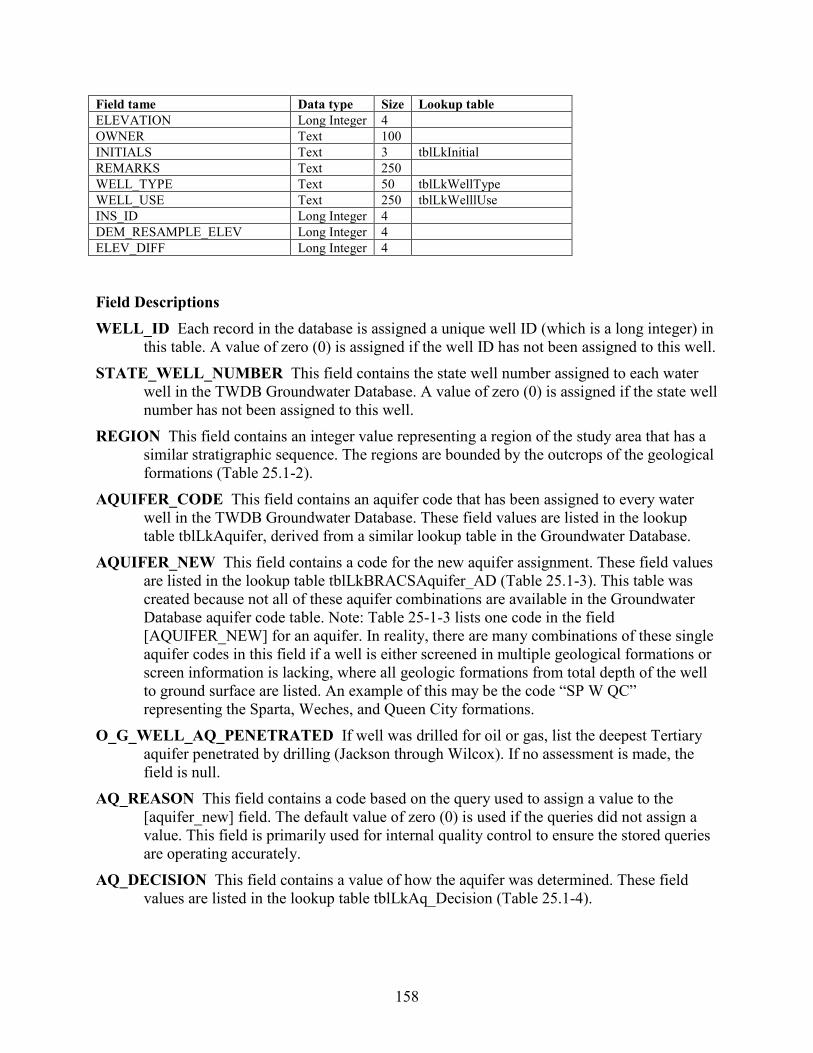
158
Field tame Data type Size Lookup table ELEVATION Long Integer 4 OWNER Text 100 INITIALS Text 3 tblLkInitial REMARKS Text 250 WELL_TYPE Text 50 tblLkWellType WELL_USE Text 250 tblLkWelllUse INS_ID Long Integer 4 DEM_RESAMPLE_ELEV Long Integer 4 ELEV_DIFF Long Integer 4 Field Descriptions WELL_ID Each record in the database is assigned a unique well ID (which is a long integer) in
this table. A value of zero (0) is assigned if the well ID has not been assigned to this well. STATE_WELL_NUMBER This field contains the state well number assigned to each water
well in the TWDB Groundwater Database. A value of zero (0) is assigned if the state well number has not been assigned to this well.
REGION This field contains an integer value representing a region of the study area that has a similar stratigraphic sequence. The regions are bounded by the outcrops of the geological formations (Table 25.1-2).
AQUIFER_CODE This field contains an aquifer code that has been assigned to every water well in the TWDB Groundwater Database. These field values are listed in the lookup table tblLkAquifer, derived from a similar lookup table in the Groundwater Database.
AQUIFER_NEW This field contains a code for the new aquifer assignment. These field values are listed in the lookup table tblLkBRACSAquifer_AD (Table 25.1-3). This table was created because not all of these aquifer combinations are available in the Groundwater Database aquifer code table. Note: Table 25-1-3 lists one code in the field [AQUIFER_NEW] for an aquifer. In reality, there are many combinations of these single aquifer codes in this field if a well is either screened in multiple geological formations or screen information is lacking, where all geologic formations from total depth of the well to ground surface are listed. An example of this may be the code “SP W QC” representing the Sparta, Weches, and Queen City formations.
O_G_WELL_AQ_PENETRATED If well was drilled for oil or gas, list the deepest Tertiary aquifer penetrated by drilling (Jackson through Wilcox). If no assessment is made, the field is null.
AQ_REASON This field contains a code based on the query used to assign a value to the [aquifer_new] field. The default value of zero (0) is used if the queries did not assign a value. This field is primarily used for internal quality control to ensure the stored queries are operating accurately.
AQ_DECISION This field contains a value of how the aquifer was determined. These field values are listed in the lookup table tblLkAq_Decision (Table 25.1-4).
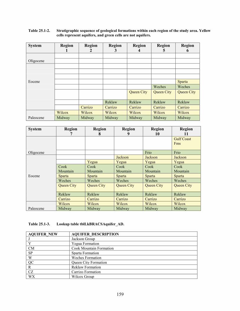
159
Table 25.1-2. Stratigraphic sequence of geological formations within each region of the study area. Yellow cells represent aquifers, and green cells are not aquifers.
System Region
1 Region
2 Region
3 Region
4 Region
5 Region
6 Oligocene Eocene Sparta Weches Weches Queen City Queen City Queen City
Reklaw Reklaw Reklaw Reklaw Carrizo Carrizo Carrizo Carrizo Carrizo Wilcox Wilcox Wilcox Wilcox Wilcox Wilcox Paleocene Midway Midway Midway Midway Midway Midway System Region
7 Region
8 Region
9 Region
10 Region
11 Gulf Coast
Fms
Oligocene Frio Frio Jackson Jackson Jackson Yegua Yegua Yegua Yegua Cook
Mountain Cook Mountain
Cook Mountain
Cook Mountain
Cook Mountain
Eocene Sparta Sparta Sparta Sparta Sparta Weches Weches Weches Weches Weches Queen City Queen City Queen City Queen City Queen City
Reklaw Reklaw Reklaw Reklaw Reklaw Carrizo Carrizo Carrizo Carrizo Carrizo Wilcox Wilcox Wilcox Wilcox Wilcox Paleocene Midway Midway Midway Midway Midway Table 25.1-3. Lookup table tblLkBRACSAquifer_AD. AQUIFER_NEW AQUIFER_DESCRIPTION J Jackson Group Y Yegua Formation CM Cook Mountain Formation SP Sparta Formation W Weches Formation QC Queen City Formation R Reklaw Formation CZ Carrizo Formation WX Wilcox Group
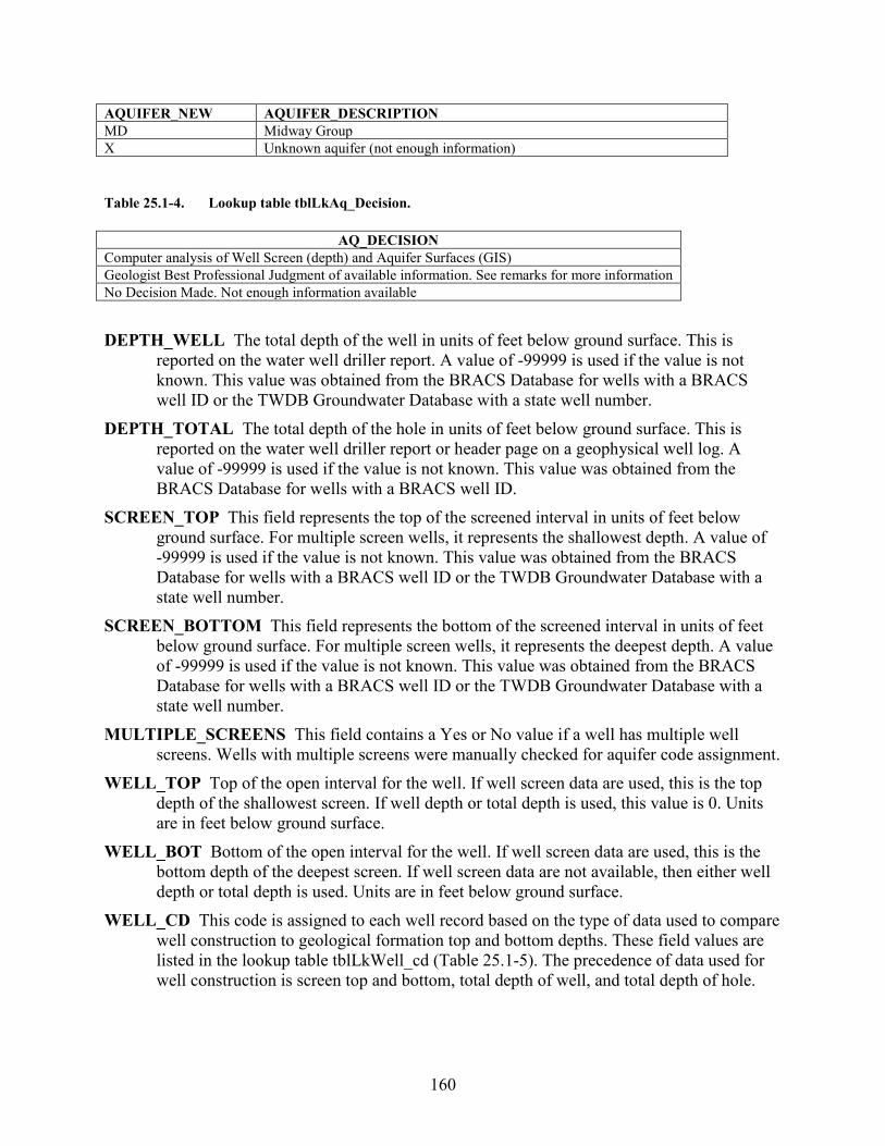
160
AQUIFER_NEW AQUIFER_DESCRIPTION MD Midway Group X Unknown aquifer (not enough information)
Table 25.1-4. Lookup table tblLkAq_Decision.
AQ_DECISION Computer analysis of Well Screen (depth) and Aquifer Surfaces (GIS) Geologist Best Professional Judgment of available information. See remarks for more information No Decision Made. Not enough information available DEPTH_WELL The total depth of the well in units of feet below ground surface. This is
reported on the water well driller report. A value of -99999 is used if the value is not known. This value was obtained from the BRACS Database for wells with a BRACS well ID or the TWDB Groundwater Database with a state well number.
DEPTH_TOTAL The total depth of the hole in units of feet below ground surface. This is reported on the water well driller report or header page on a geophysical well log. A value of -99999 is used if the value is not known. This value was obtained from the BRACS Database for wells with a BRACS well ID.
SCREEN_TOP This field represents the top of the screened interval in units of feet below ground surface. For multiple screen wells, it represents the shallowest depth. A value of -99999 is used if the value is not known. This value was obtained from the BRACS Database for wells with a BRACS well ID or the TWDB Groundwater Database with a state well number.
SCREEN_BOTTOM This field represents the bottom of the screened interval in units of feet below ground surface. For multiple screen wells, it represents the deepest depth. A value of -99999 is used if the value is not known. This value was obtained from the BRACS Database for wells with a BRACS well ID or the TWDB Groundwater Database with a state well number.
MULTIPLE_SCREENS This field contains a Yes or No value if a well has multiple well screens. Wells with multiple screens were manually checked for aquifer code assignment.
WELL_TOP Top of the open interval for the well. If well screen data are used, this is the top depth of the shallowest screen. If well depth or total depth is used, this value is 0. Units are in feet below ground surface.
WELL_BOT Bottom of the open interval for the well. If well screen data are used, this is the bottom depth of the deepest screen. If well screen data are not available, then either well depth or total depth is used. Units are in feet below ground surface.
WELL_CD This code is assigned to each well record based on the type of data used to compare well construction to geological formation top and bottom depths. These field values are listed in the lookup table tblLkWell_cd (Table 25.1-5). The precedence of data used for well construction is screen top and bottom, total depth of well, and total depth of hole.
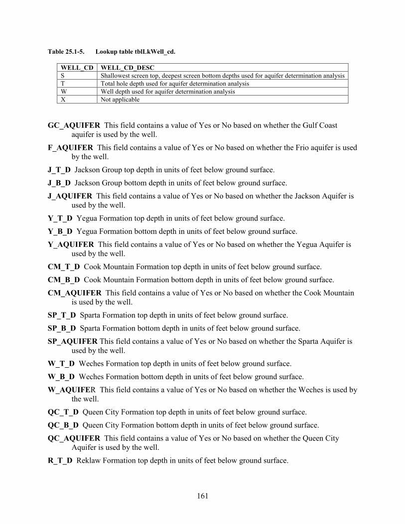
161
Table 25.1-5. Lookup table tblLkWell_cd.
GC_AQUIFER This field contains a value of Yes or No based on whether the Gulf Coast
aquifer is used by the well. F_AQUIFER This field contains a value of Yes or No based on whether the Frio aquifer is used
by the well. J_T_D Jackson Group top depth in units of feet below ground surface. J_B_D Jackson Group bottom depth in units of feet below ground surface. J_AQUIFER This field contains a value of Yes or No based on whether the Jackson Aquifer is
used by the well. Y_T_D Yegua Formation top depth in units of feet below ground surface. Y_B_D Yegua Formation bottom depth in units of feet below ground surface. Y_AQUIFER This field contains a value of Yes or No based on whether the Yegua Aquifer is
used by the well. CM_T_D Cook Mountain Formation top depth in units of feet below ground surface. CM_B_D Cook Mountain Formation bottom depth in units of feet below ground surface. CM_AQUIFER This field contains a value of Yes or No based on whether the Cook Mountain
is used by the well. SP_T_D Sparta Formation top depth in units of feet below ground surface. SP_B_D Sparta Formation bottom depth in units of feet below ground surface. SP_AQUIFER This field contains a value of Yes or No based on whether the Sparta Aquifer is
used by the well. W_T_D Weches Formation top depth in units of feet below ground surface. W_B_D Weches Formation bottom depth in units of feet below ground surface. W_AQUIFER This field contains a value of Yes or No based on whether the Weches is used by
the well. QC_T_D Queen City Formation top depth in units of feet below ground surface. QC_B_D Queen City Formation bottom depth in units of feet below ground surface. QC_AQUIFER This field contains a value of Yes or No based on whether the Queen City
Aquifer is used by the well. R_T_D Reklaw Formation top depth in units of feet below ground surface.
WELL_CD WELL_CD_DESC S Shallowest screen top, deepest screen bottom depths used for aquifer determination analysis T Total hole depth used for aquifer determination analysis W Well depth used for aquifer determination analysis X Not applicable
162
R_B_D Reklaw Formation bottom depth in units of feet below ground surface. R_AQUIFER This field contains a value of Yes or No based on whether the Reklaw is used by
the well. CZ_T_D Carrizo Formation top depth in units of feet below ground surface. CZ_B_D Carrizo Formation bottom depth in units of feet below ground surface. CZ_AQUIFER This field contains a value of Yes or No based on whether the Carrizo Aquifer is
used by the well. WX_T_D Wilcox Group top depth in units of feet below ground surface. WX_B_D Wilcox Group bottom depth in units of feet below ground surface. WX_AQUIFER This field contains a value of Yes or No based on whether the Wilcox Aquifer
is used by the well. MD_T_D Midway Group top depth in units of feet below ground surface. MD_B_D Midway Group bottom depth in units of feet below ground surface. LATDD Latitude of the well site in units of decimal degrees. Latitude is a positive value,
referring to a site north of the earth’s equator. Latitude and longitude coordinates are obtained from multiple sources. Latitude is obtained is based on a North American Datum of 1983. This value was obtained from the well location table.
LONGDD Longitude of the well site in units of decimal degrees. Longitude is a negative value, referring to a site west of the Prime Meridian in Greenwich, United Kingdom. Latitude and longitude coordinates are obtained from multiple sources. Longitude is based on a North American Datum of 1983. This value was obtained from the well location table.
ELEVATION The elevation of the well site in units of feet above mean sea level. The elevation is determined using spatial analysis in a geographic information system by comparing the well site with the 30-meter digital elevation model for Texas. This value was obtained from the well location table. A value of -99999 is used if the value is not known.
OWNER The name of the well owner. This value was obtained from the well location table. INITIALS Initials of person who last edited the record. REMARKS General remarks associated with the well record. WELL_TYPE The type of well when the well was drilled and completed. These terms are the
same as the lookup table in the TWDB Groundwater Database (Rein and Hopkins, 2008). These field values are listed in the lookup table tblLkWellType.
WELL_USE The well use when the well was drilled and completed. These terms are the same as the primary use lookup table in the TWDB Groundwater Database (Rein and Hopkins, 2008). These field values are listed in the lookup table tblLkWellUse.
INS_ID Unique ID assigned to each record to ensure the data from well records processed in GIS are precisely assigned to the corresponding database record.
163
DEM_RESAMPLE_ELEV Elevation of well site based on the BRACS study grid cell elevation that is a resample of the 30 meter digital elevation grid. This elevation was used to create the stratigraphic elevation values for each geological formation.
ELEV_DIFF This value is the difference in elevations and is calculated by: [elevation] – [dem_resample_elev]. Values mean: zero (0) is no difference in elevations, a positive value indicates the elevation based on the 30 meter DEM is higher, and a negative value indicates the dem_resample_elev is higher.
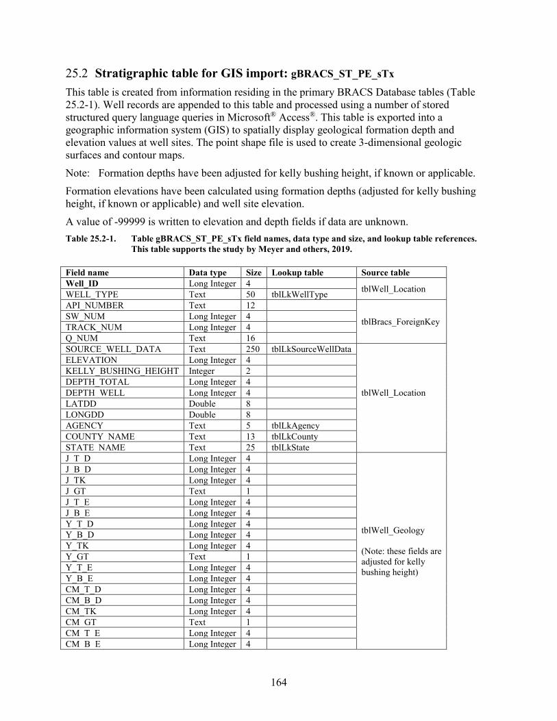
164
25.2 Stratigraphic table for GIS import: gBRACS_ST_PE_sTx This table is created from information residing in the primary BRACS Database tables (Table 25.2-1). Well records are appended to this table and processed using a number of stored structured query language queries in Microsoft® Access®. This table is exported into a geographic information system (GIS) to spatially display geological formation depth and elevation values at well sites. The point shape file is used to create 3-dimensional geologic surfaces and contour maps. Note: Formation depths have been adjusted for kelly bushing height, if known or applicable. Formation elevations have been calculated using formation depths (adjusted for kelly bushing height, if known or applicable) and well site elevation. A value of -99999 is written to elevation and depth fields if data are unknown. Table 25.2-1. Table gBRACS_ST_PE_sTx field names, data type and size, and lookup table references.
This table supports the study by Meyer and others, 2019. Field name Data type Size Lookup table Source table Well_ID Long Integer 4 tblWell_Location WELL_TYPE Text 50 tblLkWellType API_NUMBER Text 12
tblBracs_ForeignKey SW_NUM Long Integer 4 TRACK_NUM Long Integer 4 Q_NUM Text 16 SOURCE_WELL_DATA Text 250 tblLkSourceWellData
tblWell_Location
ELEVATION Long Integer 4 KELLY_BUSHING_HEIGHT Integer 2 DEPTH_TOTAL Long Integer 4 DEPTH_WELL Long Integer 4 LATDD Double 8 LONGDD Double 8 AGENCY Text 5 tblLkAgency COUNTY_NAME Text 13 tblLkCounty STATE_NAME Text 25 tblLkState J_T_D Long Integer 4
tblWell_Geology (Note: these fields are adjusted for kelly bushing height)
J_B_D Long Integer 4 J_TK Long Integer 4 J_GT Text 1 J_T_E Long Integer 4 J_B_E Long Integer 4 Y_T_D Long Integer 4 Y_B_D Long Integer 4 Y_TK Long Integer 4 Y_GT Text 1 Y_T_E Long Integer 4 Y_B_E Long Integer 4 CM_T_D Long Integer 4 CM_B_D Long Integer 4 CM_TK Long Integer 4 CM_GT Text 1 CM_T_E Long Integer 4 CM_B_E Long Integer 4
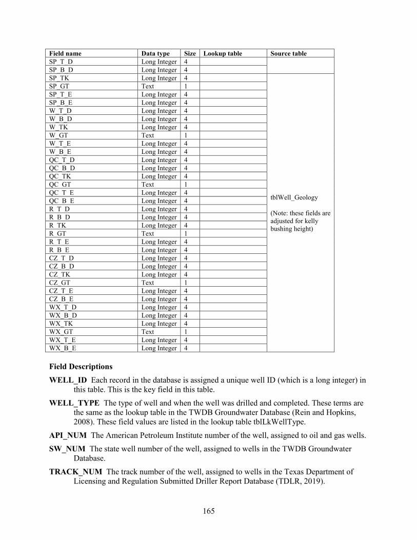
165
Field name Data type Size Lookup table Source table SP_T_D Long Integer 4 SP_B_D Long Integer 4 SP_TK Long Integer 4
tblWell_Geology (Note: these fields are adjusted for kelly bushing height)
SP_GT Text 1 SP_T_E Long Integer 4 SP_B_E Long Integer 4 W_T_D Long Integer 4 W_B_D Long Integer 4 W_TK Long Integer 4 W_GT Text 1 W_T_E Long Integer 4 W_B_E Long Integer 4 QC_T_D Long Integer 4 QC_B_D Long Integer 4 QC_TK Long Integer 4 QC_GT Text 1 QC_T_E Long Integer 4 QC_B_E Long Integer 4 R_T_D Long Integer 4 R_B_D Long Integer 4 R_TK Long Integer 4 R_GT Text 1 R_T_E Long Integer 4 R_B_E Long Integer 4 CZ_T_D Long Integer 4 CZ_B_D Long Integer 4 CZ_TK Long Integer 4 CZ_GT Text 1 CZ_T_E Long Integer 4 CZ_B_E Long Integer 4 WX_T_D Long Integer 4 WX_B_D Long Integer 4 WX_TK Long Integer 4 WX_GT Text 1 WX_T_E Long Integer 4 WX_B_E Long Integer 4 Field Descriptions WELL_ID Each record in the database is assigned a unique well ID (which is a long integer) in
this table. This is the key field in this table. WELL_TYPE The type of well and when the well was drilled and completed. These terms are
the same as the lookup table in the TWDB Groundwater Database (Rein and Hopkins, 2008). These field values are listed in the lookup table tblLkWellType.
API_NUM The American Petroleum Institute number of the well, assigned to oil and gas wells. SW_NUM The state well number of the well, assigned to wells in the TWDB Groundwater
Database. TRACK_NUM The track number of the well, assigned to wells in the Texas Department of
Licensing and Regulation Submitted Driller Report Database (TDLR, 2019).
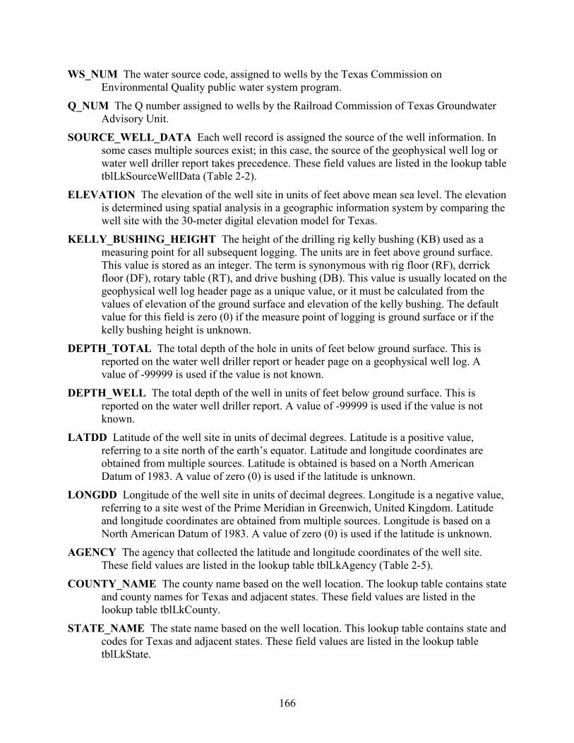
166
WS_NUM The water source code, assigned to wells by the Texas Commission on Environmental Quality public water system program.
Q_NUM The Q number assigned to wells by the Railroad Commission of Texas Groundwater Advisory Unit.
SOURCE_WELL_DATA Each well record is assigned the source of the well information. In some cases multiple sources exist; in this case, the source of the geophysical well log or water well driller report takes precedence. These field values are listed in the lookup table tblLkSourceWellData (Table 2-2).
ELEVATION The elevation of the well site in units of feet above mean sea level. The elevation is determined using spatial analysis in a geographic information system by comparing the well site with the 30-meter digital elevation model for Texas.
KELLY_BUSHING_HEIGHT The height of the drilling rig kelly bushing (KB) used as a measuring point for all subsequent logging. The units are in feet above ground surface. This value is stored as an integer. The term is synonymous with rig floor (RF), derrick floor (DF), rotary table (RT), and drive bushing (DB). This value is usually located on the geophysical well log header page as a unique value, or it must be calculated from the values of elevation of the ground surface and elevation of the kelly bushing. The default value for this field is zero (0) if the measure point of logging is ground surface or if the kelly bushing height is unknown.
DEPTH_TOTAL The total depth of the hole in units of feet below ground surface. This is reported on the water well driller report or header page on a geophysical well log. A value of -99999 is used if the value is not known.
DEPTH_WELL The total depth of the well in units of feet below ground surface. This is reported on the water well driller report. A value of -99999 is used if the value is not known.
LATDD Latitude of the well site in units of decimal degrees. Latitude is a positive value, referring to a site north of the earth’s equator. Latitude and longitude coordinates are obtained from multiple sources. Latitude is obtained is based on a North American Datum of 1983. A value of zero (0) is used if the latitude is unknown.
LONGDD Longitude of the well site in units of decimal degrees. Longitude is a negative value, referring to a site west of the Prime Meridian in Greenwich, United Kingdom. Latitude and longitude coordinates are obtained from multiple sources. Longitude is based on a North American Datum of 1983. A value of zero (0) is used if the latitude is unknown.
AGENCY The agency that collected the latitude and longitude coordinates of the well site. These field values are listed in the lookup table tblLkAgency (Table 2-5).
COUNTY_NAME The county name based on the well location. The lookup table contains state and county names for Texas and adjacent states. These field values are listed in the lookup table tblLkCounty.
STATE_NAME The state name based on the well location. This lookup table contains state and codes for Texas and adjacent states. These field values are listed in the lookup table tblLkState.
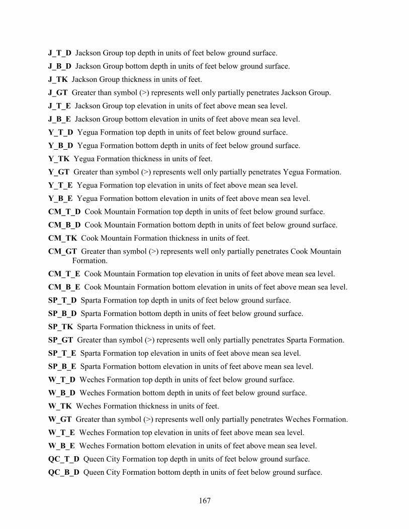
167
J_T_D Jackson Group top depth in units of feet below ground surface. J_B_D Jackson Group bottom depth in units of feet below ground surface. J_TK Jackson Group thickness in units of feet. J_GT Greater than symbol (>) represents well only partially penetrates Jackson Group. J_T_E Jackson Group top elevation in units of feet above mean sea level. J_B_E Jackson Group bottom elevation in units of feet above mean sea level. Y_T_D Yegua Formation top depth in units of feet below ground surface. Y_B_D Yegua Formation bottom depth in units of feet below ground surface. Y_TK Yegua Formation thickness in units of feet. Y_GT Greater than symbol (>) represents well only partially penetrates Yegua Formation. Y_T_E Yegua Formation top elevation in units of feet above mean sea level. Y_B_E Yegua Formation bottom elevation in units of feet above mean sea level. CM_T_D Cook Mountain Formation top depth in units of feet below ground surface. CM_B_D Cook Mountain Formation bottom depth in units of feet below ground surface. CM_TK Cook Mountain Formation thickness in units of feet. CM_GT Greater than symbol (>) represents well only partially penetrates Cook Mountain
Formation. CM_T_E Cook Mountain Formation top elevation in units of feet above mean sea level. CM_B_E Cook Mountain Formation bottom elevation in units of feet above mean sea level. SP_T_D Sparta Formation top depth in units of feet below ground surface. SP_B_D Sparta Formation bottom depth in units of feet below ground surface. SP_TK Sparta Formation thickness in units of feet. SP_GT Greater than symbol (>) represents well only partially penetrates Sparta Formation. SP_T_E Sparta Formation top elevation in units of feet above mean sea level. SP_B_E Sparta Formation bottom elevation in units of feet above mean sea level. W_T_D Weches Formation top depth in units of feet below ground surface. W_B_D Weches Formation bottom depth in units of feet below ground surface. W_TK Weches Formation thickness in units of feet. W_GT Greater than symbol (>) represents well only partially penetrates Weches Formation. W_T_E Weches Formation top elevation in units of feet above mean sea level. W_B_E Weches Formation bottom elevation in units of feet above mean sea level. QC_T_D Queen City Formation top depth in units of feet below ground surface. QC_B_D Queen City Formation bottom depth in units of feet below ground surface.
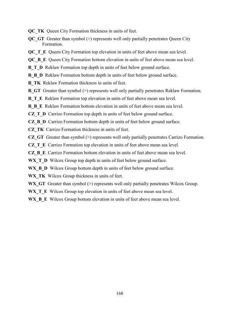
168
QC_TK Queen City Formation thickness in units of feet. QC_GT Greater than symbol (>) represents well only partially penetrates Queen City
Formation. QC_T_E Queen City Formation top elevation in units of feet above mean sea level. QC_B_E Queen City Formation bottom elevation in units of feet above mean sea level. R_T_D Reklaw Formation top depth in units of feet below ground surface. R_B_D Reklaw Formation bottom depth in units of feet below ground surface. R_TK Reklaw Formation thickness in units of feet. R_GT Greater than symbol (>) represents well only partially penetrates Reklaw Formation. R_T_E Reklaw Formation top elevation in units of feet above mean sea level. R_B_E Reklaw Formation bottom elevation in units of feet above mean sea level. CZ_T_D Carrizo Formation top depth in units of feet below ground surface. CZ_B_D Carrizo Formation bottom depth in units of feet below ground surface. CZ_TK Carrizo Formation thickness in units of feet. CZ_GT Greater than symbol (>) represents well only partially penetrates Carrizo Formation. CZ_T_E Carrizo Formation top elevation in units of feet above mean sea level. CZ_B_E Carrizo Formation bottom elevation in units of feet above mean sea level. WX_T_D Wilcox Group top depth in units of feet below ground surface. WX_B_D Wilcox Group bottom depth in units of feet below ground surface. WX_TK Wilcox Group thickness in units of feet. WX_GT Greater than symbol (>) represents well only partially penetrates Wilcox Group. WX_T_E Wilcox Group top elevation in units of feet above mean sea level. WX_B_E Wilcox Group bottom elevation in units of feet above mean sea level.

169
25.3 Master water quality: tblBracs_PE_sTx_MasterWaterQuality The master water quality table contains a copy of every water quality record in the study area organized with one record per well per date sampled with constituents in separate fields (Table 25.3-1). This design greatly simplifies the creation of GIS datasets, for without data residing in one table, data must be processed from the 6 source tables in the Groundwater Database (WaterQualityMajor, WaterQualityMinor, WaterQualityOtherUnassgined, and WaterQualityCombination) and the BRACS Database (tblBracsWaterQuality; tblBracsInfrequentConstituents). The table contains a few special fields created to support the study. Please pay close attention to the STORET codes used to populate each of the fields. STORET, short for STOrage and RETrieval, is a repository for water quality, biological, and physical data used by the U.S. Environmental Protection Agency, the U.S. Geological Survey, and other federal agencies (Rein and Hopkins, 2008). These field values are listed in the lookup table tblLkStoretCode. In some cases fields contain multiple sources of data, for example, calcium is both dissolved and total. The purpose for appending data from multiple STORET codes is to obtain a large amount of data per constituent in order to map the constituents and calibrate the geophysical well log analysis. The majority of field descriptions were obtained from the Groundwater Database Data Dictionary spreadsheet available on the TWDB website. Total dissolved solids concentration is expressed in two different forms in this table: calculated and measured. This provides the user greater flexibility in using the information. The field total dissolved solids ([TDS]) was calculated from the individual constituents and replaces the total dissolved solids concentration obtained from the input tables. It was discovered that many records from input tables contained a total dissolved solids concentration that did not match the sum of the individual constituents: some input concentrations were calculated, measured, or completely incorrect. The calculated form of total dissolved solids concentration includes multiplying the bicarbonate concentration by 0.4917. The measured form of total dissolved solids concentration does not modify the bicarbonate concentration. Table 25.3-1. Table tblBracs_PE_sTx_MasterWaterQuality field names, data type and size, and lookup
table references. Field name Data type Size Lookup table STATE_WELL_NUMBER Long Integer 4
WELL_ID Long Integer 4 mm_date Integer 2
dd_date Integer 2
yy_date Integer 2
sample_number Integer 2
SOURCE_DATA Text 200
COUNTY_NAME Text 13 tblLkCounty sample_time Long Integer 4
top_s_interval Long Integer 4
bottom_s_interval Long Integer 4
collection_remarks Text 30
reliability_rem Memo -
collecting_agency Text 250
lab_code Text 250
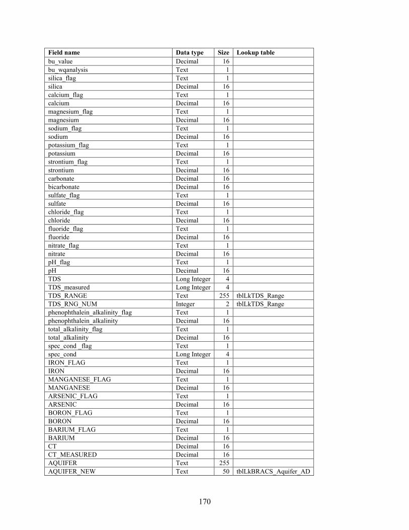
170
Field name Data type Size Lookup table bu_value Decimal 16 bu_wqanalysis Text 1
silica_flag Text 1
silica Decimal 16
calcium_flag Text 1
calcium Decimal 16
magnesium_flag Text 1
magnesium Decimal 16
sodium_flag Text 1
sodium Decimal 16
potassium_flag Text 1
potassium Decimal 16
strontium_flag Text 1
strontium Decimal 16
carbonate Decimal 16
bicarbonate Decimal 16
sulfate_flag Text 1
sulfate Decimal 16
chloride_flag Text 1
chloride Decimal 16
fluoride_flag Text 1
fluoride Decimal 16
nitrate_flag Text 1
nitrate Decimal 16
pH_flag Text 1
pH Decimal 16
TDS Long Integer 4
TDS_measured Long Integer 4 TDS_RANGE Text 255 tblLkTDS_Range TDS_RNG_NUM Integer 2 tblLkTDS_Range phenophthalein_alkalinity_flag Text 1
phenophthalein_alkalinity Decimal 16
total_alkalinity_flag Text 1
total_alkalinity Decimal 16
spec_cond _flag Text 1
spec_cond Long Integer 4
IRON_FLAG Text 1
IRON Decimal 16
MANGANESE_FLAG Text 1
MANGANESE Decimal 16
ARSENIC_FLAG Text 1 ARSENIC Decimal 16 BORON_FLAG Text 1 BORON Decimal 16 BARIUM_FLAG Text 1 BARIUM Decimal 16 CT Decimal 16
CT_MEASURED Decimal 16 AQUIFER Text 255 AQUIFER_NEW Text 50 tblLkBRACS_Aquifer_AD
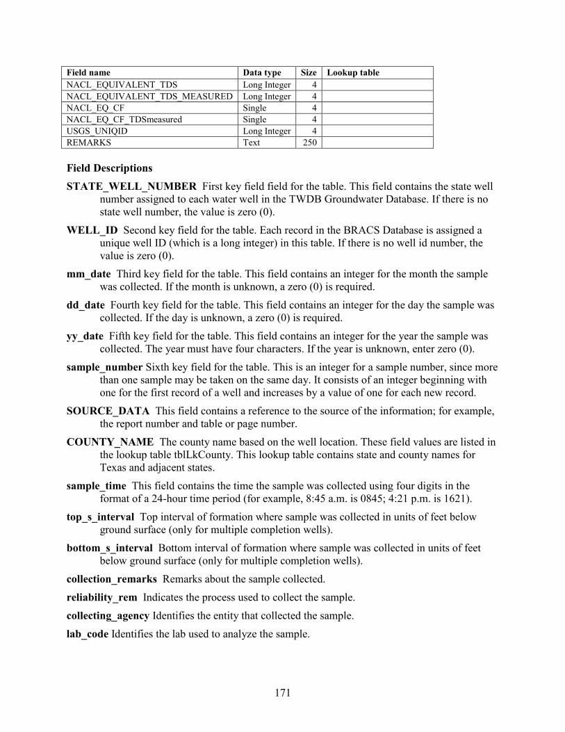
171
Field name Data type Size Lookup table NACL_EQUIVALENT_TDS Long Integer 4 NACL_EQUIVALENT_TDS_MEASURED Long Integer 4 NACL_EQ_CF Single 4 NACL_EQ_CF_TDSmeasured Single 4 USGS_UNIQID Long Integer 4 REMARKS Text 250 Field Descriptions STATE_WELL_NUMBER First key field field for the table. This field contains the state well
number assigned to each water well in the TWDB Groundwater Database. If there is no state well number, the value is zero (0).
WELL_ID Second key field for the table. Each record in the BRACS Database is assigned a unique well ID (which is a long integer) in this table. If there is no well id number, the value is zero (0).
mm_date Third key field for the table. This field contains an integer for the month the sample was collected. If the month is unknown, a zero (0) is required.
dd_date Fourth key field for the table. This field contains an integer for the day the sample was collected. If the day is unknown, a zero (0) is required.
yy_date Fifth key field for the table. This field contains an integer for the year the sample was collected. The year must have four characters. If the year is unknown, enter zero (0).
sample_number Sixth key field for the table. This is an integer for a sample number, since more than one sample may be taken on the same day. It consists of an integer beginning with one for the first record of a well and increases by a value of one for each new record.
SOURCE_DATA This field contains a reference to the source of the information; for example, the report number and table or page number.
COUNTY_NAME The county name based on the well location. These field values are listed in the lookup table tblLkCounty. This lookup table contains state and county names for Texas and adjacent states.
sample_time This field contains the time the sample was collected using four digits in the format of a 24-hour time period (for example, 8:45 a.m. is 0845; 4:21 p.m. is 1621).
top_s_interval Top interval of formation where sample was collected in units of feet below ground surface (only for multiple completion wells).
bottom_s_interval Bottom interval of formation where sample was collected in units of feet below ground surface (only for multiple completion wells).
collection_remarks Remarks about the sample collected. reliability_rem Indicates the process used to collect the sample. collecting_agency Identifies the entity that collected the sample. lab_code Identifies the lab used to analyze the sample.

172
bu_value Value of the balance/unbalanced equation. Positive or negative units in percent (for example, 3.5). Zero (0) indicates the sample is balanced.
bu_wqanalysis Indicates whether the analysis of the sample is Balanced (B) or Unbalanced (U). silica_flag Used to identify constituent concentrations below the lab's detection limits. silica Silica concentration in units of milligrams per liter. STORET 00955. calcium_flag Used to identify constituent concentrations below the lab's detection limits. calcium Calcium concentration in units of milligrams per liter. STORET 00910, 00915, 00916. magnesium_flag Used to identify constituent concentrations below the lab's detection limits. magnesium Magnesium concentration in units of milligrams per liter. STORET 00920, 00925,
00927. sodium_flag Used to identify constituent concentrations below the lab's detection limits. A
value of “c” indicates the sodium concentration was back-calculated from the difference between the sum of the determined anions, in units of milliequivalents per liter, and the determined cations in the same units (Hem, 1985).
sodium Sodium concentration in units of milligrams per liter. STORET 00929, 00930. potassium_flag Used to identify constituent concentrations below the lab's detection limits. potassium Potassium, dissolved, in units of milligrams per liter. STORET 00935, 00937. strontium_flag Used to identify constituent concentrations below the lab's detection limits. strontium Strontium concentration in units of milligrams per liter. STORET 01080. carbonate Carbonate concentration in units of milligrams per liter. STORET 00445. bicarbonate Bicarbonate concentration in units of milligrams per liter. STORET 00440. sulfate_flag Used to identify constituent concentrations below the lab's detection limits. sulfate Sulfate concentration in units of milligrams per liter. STORET 00945, 00946. chloride_flag Used to identify constituent concentrations below the lab's detection limits. chloride Chloride concentration in units of milligrams per liter. STORET 00940, 00941. fluoride_flag Used to identify constituent concentrations below the lab's detection limits. fluoride Fluoride concentration in units of milligrams per liter. STORET 00950. nitrate_flag Used to identify constituent concentrations below the lab's detection limits. nitrate Nitrate nitrogen concentration in units of milligrams per liter as NO3. STORET 71851. pH_flag Used to identify constituent concentrations below the lab's detection limits. pH pH, standard units (field measurement). STORET 00400. TDS Total dissolved solids concentration, calculated, in units of milligrams per liter (STORET
70301). Total dissolved solids concentration is calculated using one of four methods, in this order of preference, depending on the presence of required parameters:

173
(1) [silica] + [calcium] + [magnesium] + [sodium] + [potassium] + [strontium] + [carbonate ] + ([bicarbonate] · 0.4917) + [sulfate] + [chloride] + [fluoride] + [nitrate] (2) [calcium] + [magnesium] + [sodium] + [potassium] + [carbonate] + ([bicarbonate] · 0.4917) + [sulfate] + [chloride] (3) [calcium] + [magnesium] + [sodium] + [potassium] + ([bicarbonate] · 0.4917) + [sulfate] + [chloride] (4) [calcium] + [magnesium] + [sodium] + ([bicarbonate] · 0.4917) + [sulfate] + [chloride]
The parameter must not equal -99999 and the parameter flag must be null for each parameter in the equations.
There are a number of samples where sodium plus potassium was back-calculated as a sodium value. These samples are indicated with a value of “c” in the field [sodium_flag]. These samples were used to calculate total dissolved solids concentration using a variation of methods 1 through 3 above, with the exception that potassium was not used because it was included in the back-calculated sodium.
TDS_measured Total dissolved solids concentration, measured (without a bicarbonate correction), in units of milligrams per liter. Total dissolved solids concentration is calculated using one of four methods, in this order of preference, depending on the presence of required parameters: (1) [silica] + [calcium] + [magnesium] + [sodium] + [potassium] + [strontium] + [carbonate ] + [bicarbonate] + [sulfate] + [chloride] + [fluoride] + [nitrate] (2) [calcium] + [magnesium] + [sodium] + [potassium] + [carbonate] + [bicarbonate] + [sulfate] + [chloride] (3) [calcium] + [magnesium] + [sodium] + [potassium] + [bicarbonate] + [sulfate] + [chloride] (4) [calcium] + [magnesium] + [sodium] + [bicarbonate] + [sulfate] + [chloride]
The parameter must not equal -99999 and the parameter flag must be null for each parameter in the equations. There are a number of samples where sodium plus potassium was back-calculated as a sodium value. These samples are indicated with a value of “c” in the field sodium_flag. These samples were used to calculate total dissolved solids concentration using a varation of methods 1 through 3 above, with the exception that potassium was not used because it was included in the back-calculated sodium.
TDS_RANGE This field contains a value representing the range of calculated total dissolved solids concentration (field [TDS]) used for GIS analysis of brackish groundwater resources. The ranges include values, in milligrams per liter, of: 0 – 999; 1,000 – 2,999; 3,000 – 9,999; 10,000-34,999; and 35,000-100,000. These field values are listed in the lookup table tblLkTDS_Range.
TDS_RNG_NUM This field contains an integer value representing the range of total dissolved solids concentration (field [TDS_RANGE]) used for GIS analysis of brackish
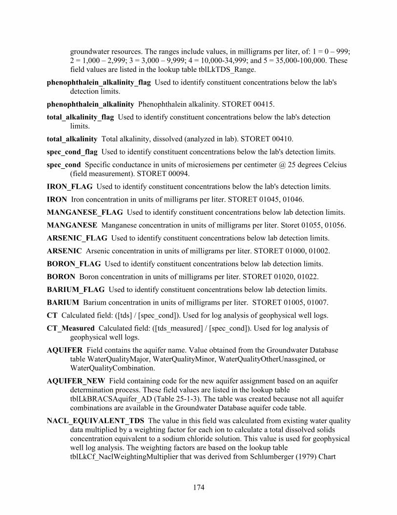
174
groundwater resources. The ranges include values, in milligrams per liter, of: 1 = 0 – 999; 2 = 1,000 – 2,999; 3 = 3,000 – 9,999; 4 = 10,000-34,999; and 5 = 35,000-100,000. These field values are listed in the lookup table tblLkTDS_Range.
phenophthalein_alkalinity_flag Used to identify constituent concentrations below the lab's detection limits.
phenophthalein_alkalinity Phenophthalein alkalinity. STORET 00415. total_alkalinity_flag Used to identify constituent concentrations below the lab's detection
limits. total_alkalinity Total alkalinity, dissolved (analyzed in lab). STORET 00410. spec_cond_flag Used to identify constituent concentrations below the lab's detection limits. spec_cond Specific conductance in units of microsiemens per centimeter @ 25 degrees Celcius
(field measurement). STORET 00094. IRON_FLAG Used to identify constituent concentrations below the lab's detection limits. IRON Iron concentration in units of milligrams per liter. STORET 01045, 01046. MANGANESE_FLAG Used to identify constituent concentrations below lab detection limits. MANGANESE Manganese concentration in units of milligrams per liter. Storet 01055, 01056. ARSENIC_FLAG Used to identify constituent concentrations below lab detection limits. ARSENIC Arsenic concentration in units of milligrams per liter. STORET 01000, 01002. BORON_FLAG Used to identify constituent concentrations below lab detection limits. BORON Boron concentration in units of milligrams per liter. STORET 01020, 01022. BARIUM_FLAG Used to identify constituent concentrations below lab detection limits. BARIUM Barium concentration in units of milligrams per liter. STORET 01005, 01007. CT Calculated field: ([tds] / [spec_cond]). Used for log analysis of geophysical well logs. CT_Measured Calculated field: ([tds_measured] / [spec_cond]). Used for log analysis of
geophysical well logs. AQUIFER Field contains the aquifer name. Value obtained from the Groundwater Database
table WaterQualityMajor, WaterQualityMinor, WaterQualityOtherUnassgined, or WaterQualityCombination.
AQUIFER_NEW Field containing code for the new aquifer assignment based on an aquifer determination process. These field values are listed in the lookup table tblLkBRACSAquifer_AD (Table 25-1-3). The table was created because not all aquifer combinations are available in the Groundwater Database aquifer code table.
NACL_EQUIVALENT_TDS The value in this field was calculated from existing water quality data multiplied by a weighting factor for each ion to calculate a total dissolved solids concentration equivalent to a sodium chloride solution. This value is used for geophysical well log analysis. The weighting factors are based on the lookup table tblLkCf_NaclWeightingMultiplier that was derived from Schlumberger (1979) Chart
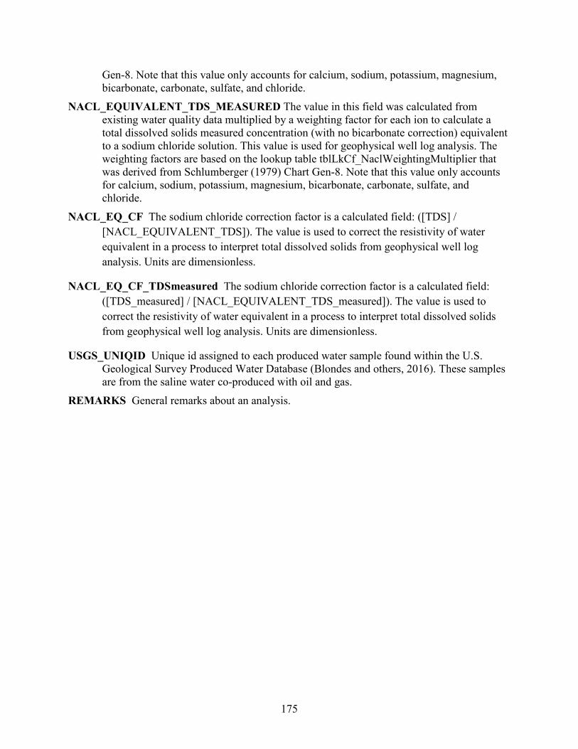
175
Gen-8. Note that this value only accounts for calcium, sodium, potassium, magnesium, bicarbonate, carbonate, sulfate, and chloride.
NACL_EQUIVALENT_TDS_MEASURED The value in this field was calculated from existing water quality data multiplied by a weighting factor for each ion to calculate a total dissolved solids measured concentration (with no bicarbonate correction) equivalent to a sodium chloride solution. This value is used for geophysical well log analysis. The weighting factors are based on the lookup table tblLkCf_NaclWeightingMultiplier that was derived from Schlumberger (1979) Chart Gen-8. Note that this value only accounts for calcium, sodium, potassium, magnesium, bicarbonate, carbonate, sulfate, and chloride.
NACL_EQ_CF The sodium chloride correction factor is a calculated field: ([TDS] / [NACL_EQUIVALENT_TDS]). The value is used to correct the resistivity of water equivalent in a process to interpret total dissolved solids from geophysical well log analysis. Units are dimensionless.
NACL_EQ_CF_TDSmeasured The sodium chloride correction factor is a calculated field: ([TDS_measured] / [NACL_EQUIVALENT_TDS_measured]). The value is used to correct the resistivity of water equivalent in a process to interpret total dissolved solids from geophysical well log analysis. Units are dimensionless.
USGS_UNIQID Unique id assigned to each produced water sample found within the U.S. Geological Survey Produced Water Database (Blondes and others, 2016). These samples are from the saline water co-produced with oil and gas.
REMARKS General remarks about an analysis.
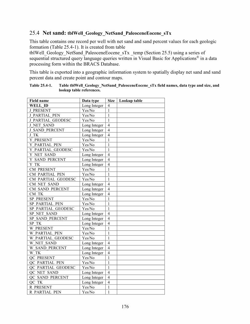
176
25.4 Net sand: tblWell_Geology_NetSand_PaleoceneEocene_sTx This table contains one record per well with net sand and sand percent values for each geologic formation (Table 25.4-1). It is created from table tblWell_Geology_NetSand_PaleoceneEocene_sTx _temp (Section 25.5) using a series of sequential structured query language queries written in Visual Basic for Applications® in a data processing form within the BRACS Database. This table is exported into a geographic information system to spatially display net sand and sand percent data and create point and contour maps. Table 25.4-1. Table tblWell_Geology_NetSand_PaleoceneEocene_sTx field names, data type and size, and
lookup table references. Field name Data type Size Lookup table WELL_ID Long Integer 4 J_PRESENT Yes/No 1 J_PARTIAL_PEN Yes/No 1 J_PARTIAL_GEODESC Yes/No 1 J_NET_SAND Long Integer 4 J_SAND_PERCENT Long Integer 4 J_TK Long Integer 4 Y_PRESENT Yes/No 1 Y_PARTIAL_PEN Yes/No 1 Y_PARTIAL_GEODESC Yes/No 1 Y_NET_SAND Long Integer 4 Y_SAND_PERCENT Long Integer 4 Y_TK Long Integer 4 CM_PRESENT Yes/No 1 CM_PARTIAL_PEN Yes/No 1 CM_PARTIAL_GEODESC Yes/No 1 CM_NET_SAND Long Integer 4 CM_SAND_PERCENT Long Integer 4 CM_TK Long Integer 4 SP_PRESENT Yes/No 1 SP_PARTIAL_PEN Yes/No 1 SP_PARTIAL_GEODESC Yes/No 1 SP_NET_SAND Long Integer 4 SP_SAND_PERCENT Long Integer 4 SP_TK Long Integer 4 W_PRESENT Yes/No 1 W_PARTIAL_PEN Yes/No 1 W_PARTIAL_GEODESC Yes/No 1 W_NET_SAND Long Integer 4 W_SAND_PERCENT Long Integer 4 W_TK Long Integer 4 QC_PRESENT Yes/No 1 QC_PARTIAL_PEN Yes/No 1 QC_PARTIAL_GEODESC Yes/No 1 QC_NET_SAND Long Integer 4 QC_SAND_PERCENT Long Integer 4 QC_TK Long Integer 4 R_PRESENT Yes/No 1 R_PARTIAL_PEN Yes/No 1
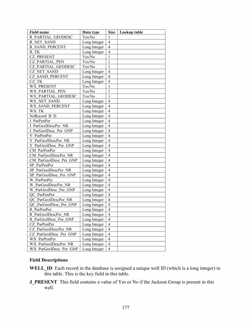
177
Field name Data type Size Lookup table R_PARTIAL_GEODESC Yes/No 1 R_NET_SAND Long Integer 4 R_SAND_PERCENT Long Integer 4 R_TK Long Integer 4 CZ_PRESENT Yes/No 1 CZ_PARTIAL_PEN Yes/No 1 CZ_PARTIAL_GEODESC Yes/No 1 CZ_NET_SAND Long Integer 4 CZ_SAND_PERCENT Long Integer 4 CZ_TK Long Integer 4 WX_PRESENT Yes/No 1 WX_PARTIAL_PEN Yes/No 1 WX_PARTIAL_GEODESC Yes/No 1 WX_NET_SAND Long Integer 4 WX_SAND_PERCENT Long Integer 4 WX_TK Long Integer 4 NoRecord_B_D Long Integer 4 J_ParPenPer Long Integer 4 J_ParGeolDescPer_NR Long Integer 4 J_ParGeolDesc_Per_GNP Long Integer 4 Y_ParPenPer Long Integer 4 Y_ParGeolDescPer_NR Long Integer 4 Y_ParGeolDesc_Per_GNP Long Integer 4 CM_ParPenPer Long Integer 4 CM_ParGeolDescPer_NR Long Integer 4 CM_ParGeolDesc_Per_GNP Long Integer 4 SP_ParPenPer Long Integer 4 SP_ParGeolDescPer_NR Long Integer 4 SP_ParGeolDesc_Per_GNP Long Integer 4 W_ParPenPer Long Integer 4 W_ParGeolDescPer_NR Long Integer 4 W_ParGeolDesc_Per_GNP Long Integer 4 QC_ParPenPer Long Integer 4 QC_ParGeolDescPer_NR Long Integer 4 QC_ParGeolDesc_Per_GNP Long Integer 4 R_ParPenPer Long Integer 4 R_ParGeolDescPer_NR Long Integer 4 R_ParGeolDesc_Per_GNP Long Integer 4 CZ_ParPenPer Long Integer 4 CZ_ParGeolDescPer_NR Long Integer 4 CZ_ParGeolDesc_Per_GNP Long Integer 4 WX_ParPenPer Long Integer 4 WX_ParGeolDescPer_NR Long Integer 4 WX_ParGeolDesc_Per_GNP Long Integer 4 Field Descriptions WELL_ID Each record in the database is assigned a unique well ID (which is a long integer) in
this table. This is the key field in this table. J_PRESENT This field contains a value of Yes or No if the Jackson Group is present in this
well.
178
J_PARTIAL_PEN This field contains a value of Yes or No if the Jackson Group is only partially penetrated by this well.
J_PARTIAL_GEODESC Field containing a value of Yes or No if the geologic description is for less than 100 percent of the Jackson Group. This can occur if the upper part of the formation is cased, or if the geologic log for the lower part is not available.
J_NET_SAND This field contains an integer representing the total thickness of sand within the Jackson Group, in units of feet.
J_SAND_PERCENT The percent of sand within the Jackson Group, calculated field: (([J_NET_SAND] / [J_TK]) · 100).
J_TK Jackson Group thickness, calculated field: ([J_B_D] - [J_T_D]). The units are feet. Y_PRESENT Field containing a value of Yes or No if the Yegua Formation is present in the
well. Y_PARTIAL_PEN This field contains a value of Yes or No if the Yegua Formation is only
partially penetrated by this well. Y_PARTIAL_GEODESC This field contains a value of Yes or No if the geologic description
is for less than 100 percent of the Yegua Formation. This can occur if the upper part of the formation is cased, or if the geologic log for the lower part of the formation is not available.
Y_NET_SAND This field contains an integer representing the total thickness of sand within the Yegua Formation, in units of feet.
Y_SAND_PERCENT The percent of sand within the Yegua Formation, calculated field: (([Y_NET_SAND] / [Y_TK]) · 100).
Y_TK Yegua Formation thickness, calculated field: ([Y_B_D] - [Y_T_D]). The units are feet. CM_PRESENT This field contains a value of Yes or No if the Cook Mountain Formation is
present in this well. CM_PARTIAL_PEN This field contains a value of Yes or No if the Cook Mountain Formation
is only partially penetrated by this well. CM_PARTIAL_GEODESC This field contains a value of Yes or No if the geologic
description is for less than 100 percent of the Cook Mountain Formation. This can occur if the upper part of the formation is cased, or if the geologic log for the lower part of the formation is not available.
CM_NET_SAND This field contains an integer representing the total thickness of sand within the Cook Mountain Formation, in units of feet.
CM_SAND_PERCENT The percent of sand within the Cook Mountain Formation, calculated field: (([CM_NET_SAND] / [CM_TK]) · 100).
CM_TK Cook Mountain Formation thickness, calculated field: ([CM_B_D] - [CM_T_D]). The units are feet.
SP_PRESENT This field contains a value of Yes or No if the Sparta Formation is present in this well.
179
SP_PARTIAL_PEN This field contains a value of Yes or No if the Sparta Formation is only partially penetrated by this well.
SP_PARTIAL_GEODESC This field contains a value of Yes or No if the geologic description is for less than 100 percent of the Sparta Formation. This can occur if the upper part of the formation is cased, or if the geologic log for the lower part of the formation is not available.
SP_NET_SAND This field contains an integer representing the total thickness of sand within the Sparta Formation, in units of feet.
SP_SAND_PERCENT The percent of sand within the Sparta Formation, calculated field: (([SP_NET_SAND] / [SP_TK]) · 100).
SP_TK Sparta Formation thickness, calculated field: ([SP_B_D] - [SP_T_D]). The units are feet.
W_PRESENT This field contains a value of Yes or No if the Weches Formation is present in this well.
W_PARTIAL_PEN This field contains a value of Yes or No if the Weches Formation is only partially penetrated by this well.
W_PARTIAL_GEODESC This field contains a value of Yes or No if the geologic description is for less than 100 percent of the Weches Formation. This can occur if the upper part of the formation is cased, or if the geologic log for the lower part of the formation is not available.
W_NET_SAND This field contains an integer representing the total thickness of sand within the Weches Formation, in units of feet.
W_SAND_PERCENT The percent of sand within the Weches Formation, calculated field: (([W_NET_SAND] / [W_TK]) · 100).
W_TK Weches Formation thickness, calculated field: ([W_B_D] - [W_T_D]). The units are feet.
QC_PRESENT This field contains a value of Yes or No if the Queen City Formation is present in this well.
QC_PARTIAL_PEN This field contains a value of Yes or No if the Queen City Formation is only partially penetrated by this well.
QC_PARTIAL_GEODESC This field contains a value of Yes or No if the geologic description is for less than 100 percent of the Queen City Formation. This can occur if the upper part of the formation is cased, or if the geologic log for the lower part of the formation is not available.
QC_NET_SAND This field contains an integer representing the total thickness of sand within the Queen City Formation, in units of feet.
QC_SAND_PERCENT The percent of sand within the Queen City Formation, calculated field: (([QC_NET_SAND] / [QC_TK]) · 100).
QC_TK Queen City Formation thickness, calculated field: ([QC_B_D] - [QC_T_D]). The units are feet.

180
R_PRESENT Field containing a value of Yes or No if Reklaw Formation is present in the well. R_PARTIAL_PEN This field contains a value of Yes or No if the Reklaw Formation is only
partially penetrated by this well. R_PARTIAL_GEODESC This field contains a value of Yes or No if the geologic description
is for less than 100 percent of the Reklaw Formation. This can occur if the upper part of the formation is cased, or if the geologic log for the lower part of the formation is not available.
R_NET_SAND This field contains an integer representing the total thickness of sand within the Reklaw Formation, in units of feet.
R_SAND_PERCENT The percent of sand within the Reklaw Formation, calculated field: (([R_NET_SAND] / [R_TK]) · 100).
R_TK Reklaw Formation thickness, calculated field: ([R_B_D] - [R_T_D]). The units are feet. CZ_PRESENT This field contains a value of Yes or No if the Carrizo Formation is present in
this well. CZ_PARTIAL_PEN This field contains a value of Yes or No if the Carrizo Formation is only
partially penetrated by this well. CZ_PARTIAL_GEODESC This field contains a value of Yes or No if the geologic description
is for less than 100 percent of the Carrizo Formation. This can occur if the upper part of the formation is cased, or if the geologic log for the lower part of the formation is not available.
CZ_NET_SAND This field contains an integer representing the total thickness of sand within the Carrizo Formation, in units of feet.
CZ_SAND_PERCENT The percent of sand within the Carrizo Formation, calculated field: (([CZ_NET_SAND] / [CZ_TK]) · 100).
CZ_TK Carrizo Formation thickness, calculated field: ([CZ_B_D] - [CZ_T_D]). The units are feet.
WX_PRESENT This field contains a value of Yes or No if the Wilcox Group is present in this well.
WX_PARTIAL_PEN This field contains a value of Yes or No if the Wilcox Group is only partially penetrated by this well.
WX_PARTIAL_GEODESC This field contains a value of Yes or No if the geologic description is for less than 100 percent of the Wilcox Group. This can occur if the upper part of the formation is cased, or if the geologic log for the lower part of the formation is not available.
WX_NET_SAND This field contains an integer representing the total thickness of sand within the Wilcox Group, in units of feet.
WX_SAND_PERCENT The percent of sand within the Wilcox Group, calculated field: (([WX_NET_SAND] / [WX_TK]) · 100).
181
WX_TK Wilcox Group thickness, calculated field: ([WX_B_D] - [WX_T_D]). The units are feet.
NoRecord_B_D This record contains the bottom depth value (units: feet) of a “no record” entry in the field [simplified_lithologic_name] in the table tblWell_Geology. A “no record” value is written to this field if there is no lithologic description for this depth range in situations of a cased well, deepended well, cavern, or lost circulation with loss of drill cuttings returned to surface. This field is used to determine how much of the geologic formation was not defined by lithology for the field [J_ParGeolDescPer_NR]. There may be zero to many no record ranges represented on a well log.
J_ParPenPer This field records the percentage of well penetration into the Jackson Group for wells that only partially penetrate the entire geologic formation. This field is calculated by: ((total depth of well – formation_top depth) / formation thickness) · 100.
J_ParGeolDescPer_NR This field records the percentage of missing lithologic data in the Jackson Group based on the depth of the “no record” value in the field [NoRecord_B_D]. This field is calculated by: ((“no record” bottom depth – formation top depth) / formation thickness) · 100.
J_ParGeolDesc_Per_GNP This field records the percentage of missing lithologic data in the Jackson Group based on a value of either “geology not processed – log image cut off” or “geology not processed, but available on log” (GNP) that are recorded in the field [simplified_lithologic_name] in the table tblWell_Geology and whose depth ranges overlap the Jackson Group. The field is calculated by one of three equations, based on one of the three common scenarios: (1) entire formation is not described = 100 percent, (2) GNP overlaps the bottom of the formation, ((formation bottom depth – GNP top depth) / formation thickness ·100), or (3) GNP overlaps the top of the formation, ((GNP bottom depth – formation top depth) / formation thickness ·100).
Y_ParPenPer This field records the percentage of well penetration into the Yegua Formation for wells that only partially penetrate the entire geologic formation. This field is calculated by: ((total depth of well – formation_top depth) / formation thickness) · 100.
Y_ParGeolDescPer_NR This field records the percentage of missing lithologic data in the Yegua Formation based on the depth of the “no record” value in the field [NoRecord_B_D]. This field is calculated by: ((“no record” bottom depth – formation top depth) / formation thickness) · 100.
Y_ParGeolDesc_Per_GNP This field records the percentage of missing lithologic data in the Yegua Formation based on a value of either “geology not processed – log image cut off” or “geology not processed, but available on log” (GNP) that are recorded in the field [simplified_lithologic_name] in the table tblWell_Geology and whose depth ranges overlap the Yegua Formation. The field is calculated by one of three equations, based on one of the three common scenarios: (1) entire formation is not described = 100 percent, (2) GNP overlaps the bottom of the formation, ((formation bottom depth – GNP top depth) / formation thickness ·100), or (3) GNP overlaps the top of the formation, ((GNP bottom depth – formation top depth) / formation thickness ·100).
182
CM_ParPenPer This field records the percentage of well penetration into the Cook Mountain Formation for wells that only partially penetrate the entire geologic formation. This field is calculated by: ((total depth of well – formation_top depth) / formation thickness) · 100.
CM_ParGeolDescPer_NR This field records the percentage of missing lithologic data in the Cook Mountain Formation based on the depth of the “no record” value in the field [NoRecord_B_D]. This field is calculated by: ((“no record” bottom depth – formation top depth) / formation thickness) · 100.
CM_ParGeolDesc_Per_GNP This field records the percentage of missing lithologic data in the Cook Mountain Formation based on a value of either “geology not processed – log image cut off” or “geology not processed, but available on log” (GNP) that are recorded in the field [simplified_lithologic_name] in the table tblWell_Geology and whose depth ranges overlap the Cook Mountain Formation. The field is calculated by one of three equations, based on one of the three common scenarios: (1) entire formation is not described = 100 percent, (2) GNP overlaps the bottom of the formation, ((formation bottom depth – GNP top depth) / formation thickness ·100), or (3) GNP overlaps the top of the formation, ((GNP bottom depth – formation top depth) / formation thickness ·100).
SP_ParPenPer This field records the percentage of well penetration into the Sparta Formation for wells that only partially penetrate the entire geologic formation. This field is calculated by: ((total depth of well – formation_top depth) / formation thickness) · 100.
SP_ParGeolDescPer_NR This field records the percentage of missing lithologic data in the Sparta Formation based on the depth of the “no record” value in the field [NoRecord_B_D]. This field is calculated by: ((“no record” bottom depth – formation top depth) / formation thickness) · 100.
SP_ParGeolDesc_Per_GNP This field records the percentage of missing lithologic data in the Sparta Formation based on a value of either “geology not processed – log image cut off” or “geology not processed, but available on log” (GNP) that are recorded in the field [simplified_lithologic_name] in the table tblWell_Geology and whose depth ranges overlap the Sparta Formation. The field is calculated by one of three equations, based on one of the three common scenarios: (1) entire formation is not described = 100 percent, (2) GNP overlaps the bottom of the formation, ((formation bottom depth – GNP top depth) / formation thickness ·100), or (3) GNP overlaps the top of the formation, ((GNP bottom depth – formation top depth) / formation thickness ·100).
W_ParPenPer This field records the percentage of well penetration into the Weches Formation for wells that only partially penetrate the entire geologic formation. This field is calculated by: ((total depth of well – formation_top depth) / formation thickness) · 100.
W_ParGeolDescPer_NR This field records the percentage of missing lithologic data in the Weches Formation based on the depth of the “no record” value in the field [NoRecord_B_D]. This field is calculated by: ((“no record” bottom depth – formation top depth) / formation thickness) · 100.
W_ParGeolDesc_Per_GNP This field records the percentage of missing lithologic data in the Weches Formation based on a value of either “geology not processed – log image cut off” or “geology not processed, but available on log” (GNP) that are recorded in the field [simplified_lithologic_name] in the table tblWell_Geology and whose depth ranges
183
overlap the Weches Formation. The field is calculated by one of three equations, based on one of the three common scenarios: (1) entire formation is not described = 100 percent, (2) GNP overlaps the bottom of the formation, ((formation bottom depth – GNP top depth) / formation thickness ·100), or (3) GNP overlaps the top of the formation, ((GNP bottom depth – formation top depth) / formation thickness ·100).
QC_ParPenPer This field records the percentage of well penetration into the Queen City Formation for wells that only partially penetrate the entire geologic formation. This field is calculated by: ((total depth of well – formation_top depth) / formation thickness) · 100.
QC_ParGeolDescPer_NR This field records the percentage of missing lithologic data in the Queen City Formation based on the depth of the “no record” value in the field [NoRecord_B_D]. This field is calculated by: ((“no record” bottom depth – formation top depth) / formation thickness) · 100.
QC_ParGeolDesc_Per_GNP This field records the percentage of missing lithologic data in the Queen City Formation based on a value of either “geology not processed – log image cut off” or “geology not processed, but available on log” (GNP) that are recorded in the field [simplified_lithologic_name] in the table tblWell_Geology and whose depth ranges overlap the Queen City Formation. The field is calculated by one of three equations, based on one of the three common scenarios: (1) entire formation is not described = 100 percent, (2) GNP overlaps the bottom of the formation, ((formation bottom depth – GNP top depth) / formation thickness ·100), or (3) GNP overlaps the top of the formation, ((GNP bottom depth – formation top depth) / formation thickness ·100).
R_ParPenPer This field records the percentage of well penetration into the Reklaw Formation for wells that only partially penetrate the entire geologic formation. This field is calculated by: ((total depth of well – formation_top depth) / formation thickness) · 100.
R_ParGeolDescPer_NR This field records the percentage of missing lithologic data in the Reklaw Formation based on the depth of the “no record” value in the field [NoRecord_B_D]. This field is calculated by: ((“no record” bottom depth – formation top depth) / formation thickness) · 100.
R_ParGeolDesc_Per_GNP This field records the percentage of missing lithologic data in the Reklaw Formation based on a value of either “geology not processed – log image cut off” or “geology not processed, but available on log” (GNP) that are recorded in the field [simplified_lithologic_name] in the table tblWell_Geology and whose depth ranges overlap the Reklaw Formation. The field is calculated by one of three equations, based on one of the three common scenarios: (1) entire formation is not described = 100 percent, (2) GNP overlaps the bottom of the formation, ((formation bottom depth – GNP top depth) / formation thickness ·100), or (3) GNP overlaps the top of the formation, ((GNP bottom depth – formation top depth) / formation thickness ·100).
CZ_ParPenPer This field records the percentage of well penetration into the Carrizo Formation for wells that only partially penetrate the entire geologic formation. This field is calculated by: ((total depth of well – formation_top depth) / formation thickness) · 100.
CZ_ParGeolDescPer_NR This field records the percentage of missing lithologic data in the Carrizo Formation based on the depth of the “no record” value in the field
184
[NoRecord_B_D]. This field is calculated by: ((“no record” bottom depth – formation top depth) / formation thickness) · 100.
CZ_ParGeolDesc_Per_GNP This field records the percentage of missing lithologic data in the Carrizo Formation based on a value of either “geology not processed – log image cut off” or “geology not processed, but available on log” (GNP) that are recorded in the field [simplified_lithologic_name] in the table tblWell_Geology and whose depth ranges overlap the Carrizo Formation. The field is calculated by one of three equations, based on one of the three common scenarios: (1) entire formation is not described = 100 percent, (2) GNP overlaps the bottom of the formation, ((formation bottom depth – GNP top depth) / formation thickness ·100), or (3) GNP overlaps the top of the formation, ((GNP bottom depth – formation top depth) / formation thickness ·100).
WX_ParPenPer This field records the percentage of well penetration into the Wilcox Formation for wells that only partially penetrate the entire geologic formation. This field is calculated by: ((total depth of well – formation_top depth) / formation thickness) · 100.
WX_ParGeolDescPer_NR This field records the percentage of missing lithologic data in the Wilcox Formation based on the depth of the “no record” value in the field [NoRecord_B_D]. This field is calculated by: ((“no record” bottom depth – formation top depth) / formation thickness) · 100.
WX_ParGeolDesc_Per_GNP This field records the percentage of missing lithologic data in the Wilcox Formation based on a value of either “geology not processed – log image cut off” or “geology not processed, but available on log” (GNP) that are recorded in the field [simplified_lithologic_name] in the table tblWell_Geology and whose depth ranges overlap the Wilcox Formation. The field is calculated by one of three equations, based on one of the three common scenarios: (1) entire formation is not described = 100 percent, (2) GNP overlaps the bottom of the formation, ((formation bottom depth – GNP top depth) / formation thickness ·100), or (3) GNP overlaps the top of the formation, ((GNP bottom depth – formation top depth) / formation thickness ·100).
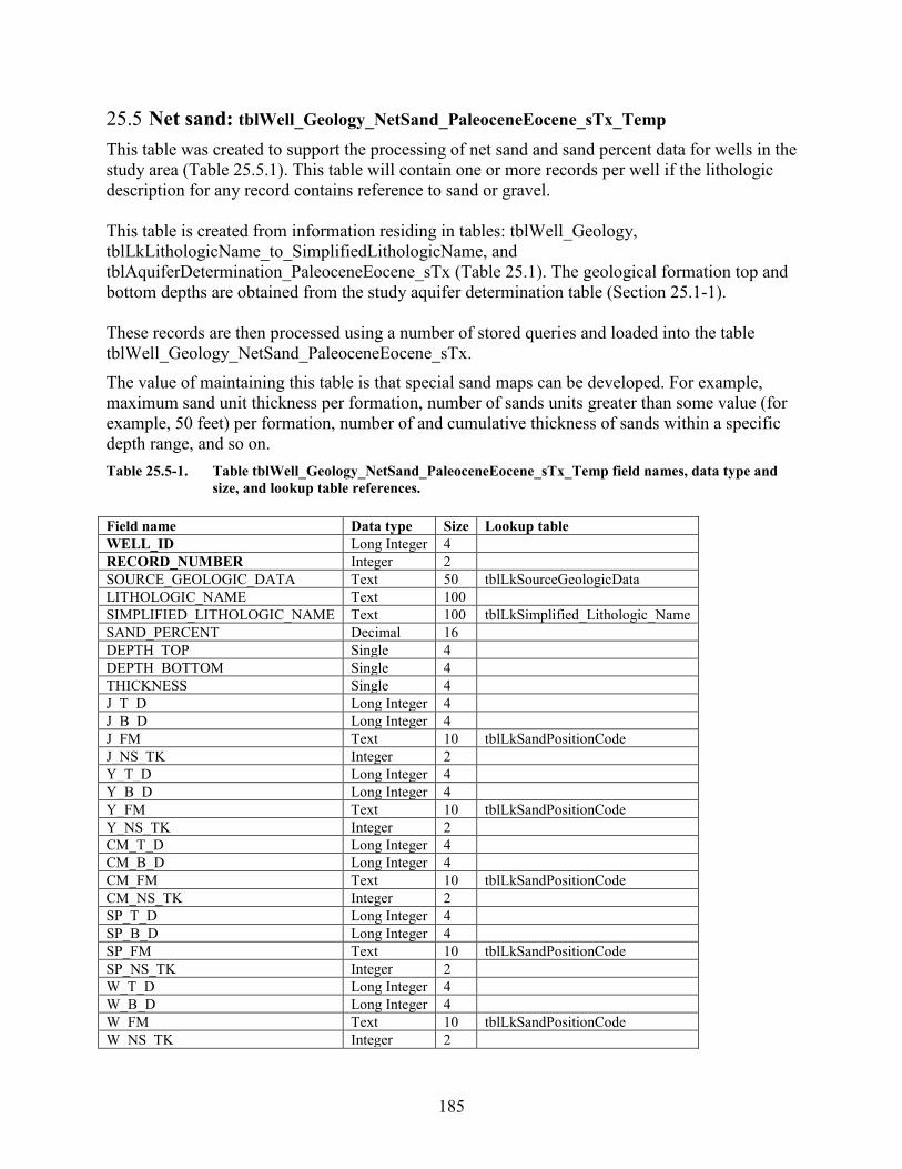
185
25.5 Net sand: tblWell_Geology_NetSand_PaleoceneEocene_sTx_Temp This table was created to support the processing of net sand and sand percent data for wells in the study area (Table 25.5.1). This table will contain one or more records per well if the lithologic description for any record contains reference to sand or gravel. This table is created from information residing in tables: tblWell_Geology, tblLkLithologicName_to_SimplifiedLithologicName, and tblAquiferDetermination_PaleoceneEocene_sTx (Table 25.1). The geological formation top and bottom depths are obtained from the study aquifer determination table (Section 25.1-1). These records are then processed using a number of stored queries and loaded into the table tblWell_Geology_NetSand_PaleoceneEocene_sTx. The value of maintaining this table is that special sand maps can be developed. For example, maximum sand unit thickness per formation, number of sands units greater than some value (for example, 50 feet) per formation, number of and cumulative thickness of sands within a specific depth range, and so on. Table 25.5-1. Table tblWell_Geology_NetSand_PaleoceneEocene_sTx_Temp field names, data type and
size, and lookup table references. Field name Data type Size Lookup table WELL_ID Long Integer 4 RECORD_NUMBER Integer 2 SOURCE_GEOLOGIC_DATA Text 50 tblLkSourceGeologicData LITHOLOGIC_NAME Text 100 SIMPLIFIED_LITHOLOGIC_NAME Text 100 tblLkSimplified_Lithologic_Name SAND_PERCENT Decimal 16 DEPTH_TOP Single 4 DEPTH_BOTTOM Single 4 THICKNESS Single 4 J_T_D Long Integer 4 J_B_D Long Integer 4 J_FM Text 10 tblLkSandPositionCode J_NS_TK Integer 2 Y_T_D Long Integer 4 Y_B_D Long Integer 4 Y_FM Text 10 tblLkSandPositionCode Y_NS_TK Integer 2 CM_T_D Long Integer 4 CM_B_D Long Integer 4 CM_FM Text 10 tblLkSandPositionCode CM_NS_TK Integer 2 SP_T_D Long Integer 4 SP_B_D Long Integer 4 SP_FM Text 10 tblLkSandPositionCode SP_NS_TK Integer 2 W_T_D Long Integer 4 W_B_D Long Integer 4 W_FM Text 10 tblLkSandPositionCode W_NS_TK Integer 2
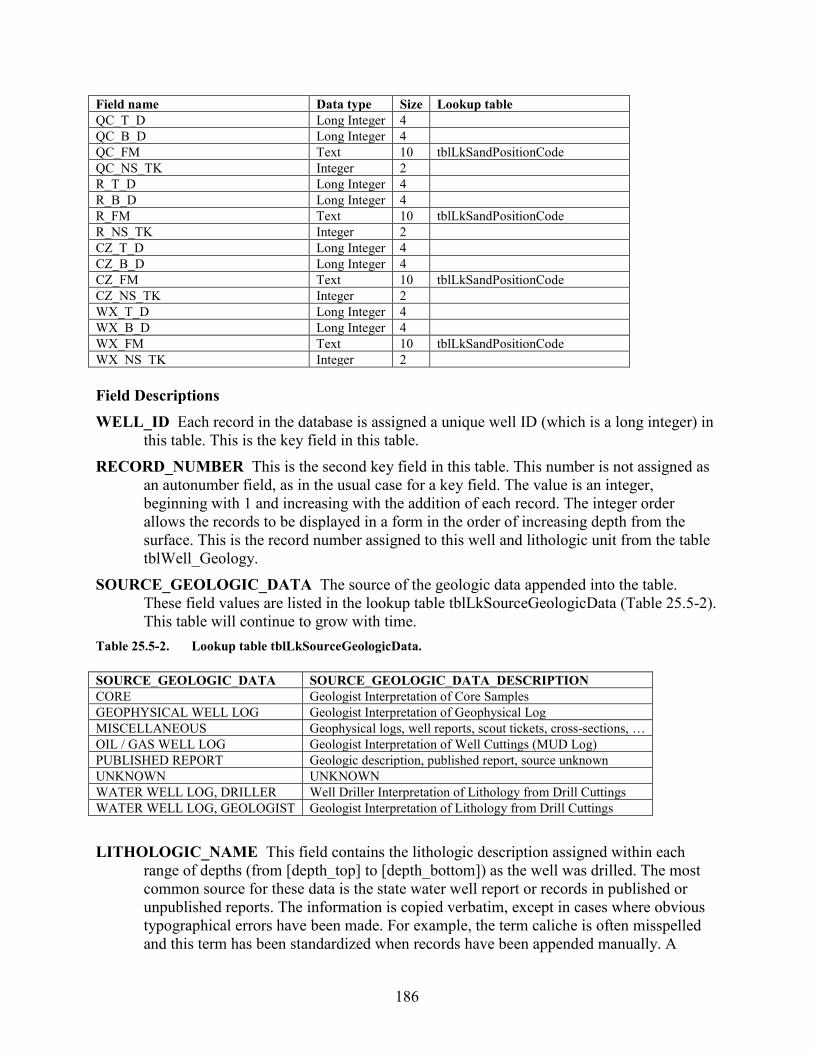
186
Field name Data type Size Lookup table QC_T_D Long Integer 4 QC_B_D Long Integer 4 QC_FM Text 10 tblLkSandPositionCode QC_NS_TK Integer 2 R_T_D Long Integer 4 R_B_D Long Integer 4 R_FM Text 10 tblLkSandPositionCode R_NS_TK Integer 2 CZ_T_D Long Integer 4 CZ_B_D Long Integer 4 CZ_FM Text 10 tblLkSandPositionCode CZ_NS_TK Integer 2 WX_T_D Long Integer 4 WX_B_D Long Integer 4 WX_FM Text 10 tblLkSandPositionCode WX_NS_TK Integer 2 Field Descriptions WELL_ID Each record in the database is assigned a unique well ID (which is a long integer) in
this table. This is the key field in this table. RECORD_NUMBER This is the second key field in this table. This number is not assigned as
an autonumber field, as in the usual case for a key field. The value is an integer, beginning with 1 and increasing with the addition of each record. The integer order allows the records to be displayed in a form in the order of increasing depth from the surface. This is the record number assigned to this well and lithologic unit from the table tblWell_Geology.
SOURCE_GEOLOGIC_DATA The source of the geologic data appended into the table. These field values are listed in the lookup table tblLkSourceGeologicData (Table 25.5-2). This table will continue to grow with time.
Table 25.5-2. Lookup table tblLkSourceGeologicData. SOURCE_GEOLOGIC_DATA SOURCE_GEOLOGIC_DATA_DESCRIPTION CORE Geologist Interpretation of Core Samples GEOPHYSICAL WELL LOG Geologist Interpretation of Geophysical Log MISCELLANEOUS Geophysical logs, well reports, scout tickets, cross-sections, … OIL / GAS WELL LOG Geologist Interpretation of Well Cuttings (MUD Log) PUBLISHED REPORT Geologic description, published report, source unknown UNKNOWN UNKNOWN WATER WELL LOG, DRILLER Well Driller Interpretation of Lithology from Drill Cuttings WATER WELL LOG, GEOLOGIST Geologist Interpretation of Lithology from Drill Cuttings LITHOLOGIC_NAME This field contains the lithologic description assigned within each
range of depths (from [depth_top] to [depth_bottom]) as the well was drilled. The most common source for these data is the state water well report or records in published or unpublished reports. The information is copied verbatim, except in cases where obvious typographical errors have been made. For example, the term caliche is often misspelled and this term has been standardized when records have been appended manually. A
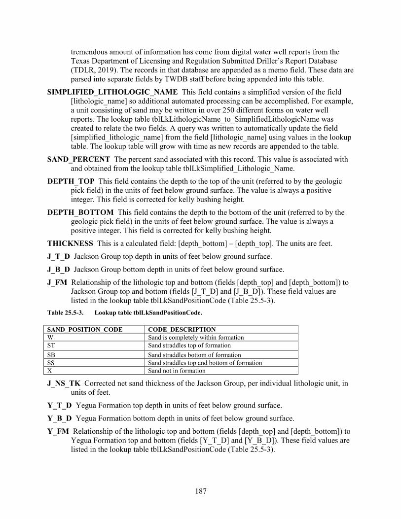
187
tremendous amount of information has come from digital water well reports from the Texas Department of Licensing and Regulation Submitted Driller’s Report Database (TDLR, 2019). The records in that database are appended as a memo field. These data are parsed into separate fields by TWDB staff before being appended into this table.
SIMPLIFIED_LITHOLOGIC_NAME This field contains a simplified version of the field [lithologic_name] so additional automated processing can be accomplished. For example, a unit consisting of sand may be written in over 250 different forms on water well reports. The lookup table tblLkLithologicName_to_SimplifiedLithologicName was created to relate the two fields. A query was written to automatically update the field [simplified_lithologic_name] from the field [lithologic_name] using values in the lookup table. The lookup table will grow with time as new records are appended to the table.
SAND_PERCENT The percent sand associated with this record. This value is associated with and obtained from the lookup table tblLkSimplified_Lithologic_Name.
DEPTH_TOP This field contains the depth to the top of the unit (referred to by the geologic pick field) in the units of feet below ground surface. The value is always a positive integer. This field is corrected for kelly bushing height.
DEPTH_BOTTOM This field contains the depth to the bottom of the unit (referred to by the geologic pick field) in the units of feet below ground surface. The value is always a positive integer. This field is corrected for kelly bushing height.
THICKNESS This is a calculated field: [depth_bottom] – [depth_top]. The units are feet. J_T_D Jackson Group top depth in units of feet below ground surface. J_B_D Jackson Group bottom depth in units of feet below ground surface. J_FM Relationship of the lithologic top and bottom (fields [depth_top] and [depth_bottom]) to
Jackson Group top and bottom (fields [J_T_D] and [J_B_D]). These field values are listed in the lookup table tblLkSandPositionCode (Table 25.5-3).
Table 25.5-3. Lookup table tblLkSandPositionCode. SAND_POSITION_CODE CODE_DESCRIPTION W Sand is completely within formation ST Sand straddles top of formation SB Sand straddles bottom of formation SS Sand straddles top and bottom of formation X Sand not in formation
J_NS_TK Corrected net sand thickness of the Jackson Group, per individual lithologic unit, in units of feet.
Y_T_D Yegua Formation top depth in units of feet below ground surface. Y_B_D Yegua Formation bottom depth in units of feet below ground surface. Y_FM Relationship of the lithologic top and bottom (fields [depth_top] and [depth_bottom]) to
Yegua Formation top and bottom (fields [Y_T_D] and [Y_B_D]). These field values are listed in the lookup table tblLkSandPositionCode (Table 25.5-3).
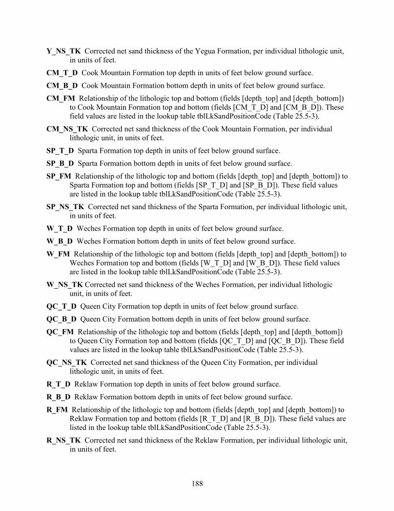
188
Y_NS_TK Corrected net sand thickness of the Yegua Formation, per individual lithologic unit, in units of feet.
CM_T_D Cook Mountain Formation top depth in units of feet below ground surface. CM_B_D Cook Mountain Formation bottom depth in units of feet below ground surface. CM_FM Relationship of the lithologic top and bottom (fields [depth_top] and [depth_bottom])
to Cook Mountain Formation top and bottom (fields [CM_T_D] and [CM_B_D]). These field values are listed in the lookup table tblLkSandPositionCode (Table 25.5-3).
CM_NS_TK Corrected net sand thickness of the Cook Mountain Formation, per individual lithologic unit, in units of feet.
SP_T_D Sparta Formation top depth in units of feet below ground surface. SP_B_D Sparta Formation bottom depth in units of feet below ground surface. SP_FM Relationship of the lithologic top and bottom (fields [depth_top] and [depth_bottom]) to
Sparta Formation top and bottom (fields [SP_T_D] and [SP_B_D]). These field values are listed in the lookup table tblLkSandPositionCode (Table 25.5-3).
SP_NS_TK Corrected net sand thickness of the Sparta Formation, per individual lithologic unit, in units of feet.
W_T_D Weches Formation top depth in units of feet below ground surface. W_B_D Weches Formation bottom depth in units of feet below ground surface. W_FM Relationship of the lithologic top and bottom (fields [depth_top] and [depth_bottom]) to
Weches Formation top and bottom (fields [W_T_D] and [W_B_D]). These field values are listed in the lookup table tblLkSandPositionCode (Table 25.5-3).
W_NS_TK Corrected net sand thickness of the Weches Formation, per individual lithologic unit, in units of feet.
QC_T_D Queen City Formation top depth in units of feet below ground surface. QC_B_D Queen City Formation bottom depth in units of feet below ground surface. QC_FM Relationship of the lithologic top and bottom (fields [depth_top] and [depth_bottom])
to Queen City Formation top and bottom (fields [QC_T_D] and [QC_B_D]). These field values are listed in the lookup table tblLkSandPositionCode (Table 25.5-3).
QC_NS_TK Corrected net sand thickness of the Queen City Formation, per individual lithologic unit, in units of feet.
R_T_D Reklaw Formation top depth in units of feet below ground surface. R_B_D Reklaw Formation bottom depth in units of feet below ground surface. R_FM Relationship of the lithologic top and bottom (fields [depth_top] and [depth_bottom]) to
Reklaw Formation top and bottom (fields [R_T_D] and [R_B_D]). These field values are listed in the lookup table tblLkSandPositionCode (Table 25.5-3).
R_NS_TK Corrected net sand thickness of the Reklaw Formation, per individual lithologic unit, in units of feet.
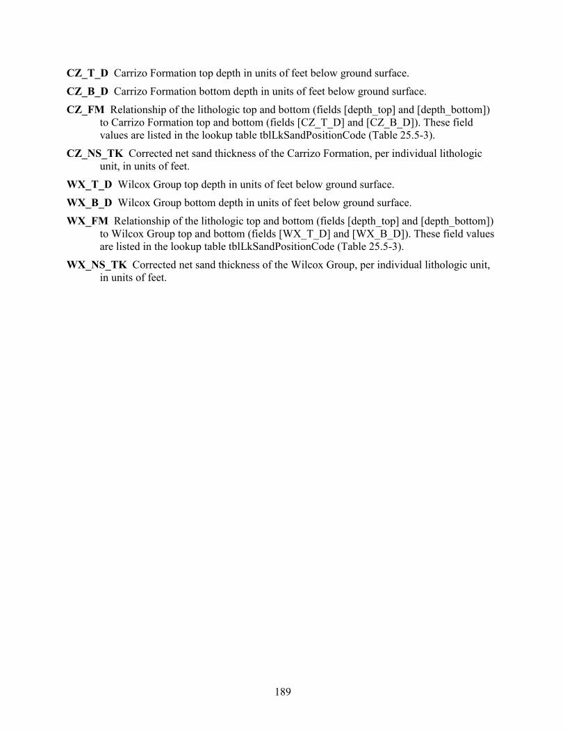
189
CZ_T_D Carrizo Formation top depth in units of feet below ground surface. CZ_B_D Carrizo Formation bottom depth in units of feet below ground surface. CZ_FM Relationship of the lithologic top and bottom (fields [depth_top] and [depth_bottom])
to Carrizo Formation top and bottom (fields [CZ_T_D] and [CZ_B_D]). These field values are listed in the lookup table tblLkSandPositionCode (Table 25.5-3).
CZ_NS_TK Corrected net sand thickness of the Carrizo Formation, per individual lithologic unit, in units of feet.
WX_T_D Wilcox Group top depth in units of feet below ground surface. WX_B_D Wilcox Group bottom depth in units of feet below ground surface. WX_FM Relationship of the lithologic top and bottom (fields [depth_top] and [depth_bottom])
to Wilcox Group top and bottom (fields [WX_T_D] and [WX_B_D]). These field values are listed in the lookup table tblLkSandPositionCode (Table 25.5-3).
WX_NS_TK Corrected net sand thickness of the Wilcox Group, per individual lithologic unit, in units of feet.

190
25.6 Net sand: tblWell_Geology_NetSand_PaleoceneEocene_sTx_Well_Decisions
This table was created to capture a decision on whether to use or not use a net sand value for a given geological formation during the preparation of the GIS raster dataset (Table 25.6.1). The table also captures the reason why a data point was not used and in some cases if staff did use a data point using best professional judgement. Table 25.6-1. Table tblWell_Geology_NetSand_PaleoceneEocene_sTx_Well_Decisions field names, data
type and size, and lookup table references. Field name Data type Size Lookup table WELL_ID Long Integer 4 J_UseWell Yes/No 1 J_No_Reason Text 255 Y_UseWell Yes/No 1 Y_No_Reason Text 255 CM_UseWell Yes/No 1 CM_No_Reason Text 255 SP_UseWell Yes/No 1 SP_No_Reason Text 255 W_UseWell Yes/No 1 W_No_Reason Text 255 QC_UseWell Yes/No 1 QC_No_Reason Text 255 R_UseWell Yes/No 1 R_No_Reason Text 255 CZ_UseWell Yes/No 1 CZ_No_Reason Text 255 WX_UseWell Yes/No 1 WX_No_Reason Text 255 WX_YoakumChannel Yes/No 1 Field Descriptions WELL_ID Each record in the database is assigned a unique well ID (which is a long integer) in
this table. This is the key field in this table. J_UseWell Jackson Group. Use this well for net sand map generation in GIS (Yes/No). J_No_Reason Jackson Group. The reason(s) that this well record was either not used for net
sand map generation. In some circumstances this field will record a reason why the well was used for net sand map generation.
Y_UseWell Yegua Formation. Use this well for net sand map generation in GIS (Yes/No). Y_No_Reason Yegua Formation. The reason(s) that this well record was either not used for net
sand map generation. In some circumstances this field will record a reason why the well was used for net sand map generation.
CM_UseWell Cook Mountain Formation. Use this well for net sand map generation in GIS (Yes/No).
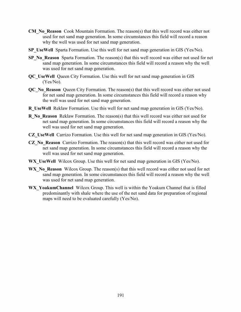
191
CM_No_Reason Cook Mountain Formation. The reason(s) that this well record was either not used for net sand map generation. In some circumstances this field will record a reason why the well was used for net sand map generation.
SP_UseWell Sparta Formation. Use this well for net sand map generation in GIS (Yes/No). SP_No_Reason Sparta Formation. The reason(s) that this well record was either not used for net
sand map generation. In some circumstances this field will record a reason why the well was used for net sand map generation.
QC_UseWell Queen City Formation. Use this well for net sand map generation in GIS (Yes/No).
QC_No_Reason Queen City Formation. The reason(s) that this well record was either not used for net sand map generation. In some circumstances this field will record a reason why the well was used for net sand map generation.
R_UseWell Reklaw Formation. Use this well for net sand map generation in GIS (Yes/No). R_No_Reason Reklaw Formation. The reason(s) that this well record was either not used for
net sand map generation. In some circumstances this field will record a reason why the well was used for net sand map generation.
CZ_UseWell Carrizo Formation. Use this well for net sand map generation in GIS (Yes/No). CZ_No_Reason Carrizo Formation. The reason(s) that this well record was either not used for
net sand map generation. In some circumstances this field will record a reason why the well was used for net sand map generation.
WX_UseWell Wilcox Group. Use this well for net sand map generation in GIS (Yes/No). WX_No_Reason Wilcox Group. The reason(s) that this well record was either not used for net
sand map generation. In some circumstances this field will record a reason why the well was used for net sand map generation.
WX_YoakumChannel Wilcox Group. This well is within the Yoakum Channel that is filled predominantly with shale where the use of the net sand data for preparation of regional maps will need to be evaluated carefully (Yes/No).
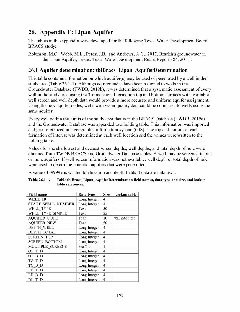
192
26. Appendix F: Lipan Aquifer The tables in this appendix were developed for the following Texas Water Development Board BRACS study: Robinson, M.C., Webb, M.L., Perez, J.B., and Andrews, A.G., 2017, Brackish groundwater in
the Lipan Aquifer, Texas: Texas Water Development Board Report 384, 201 p.
26.1 Aquifer determination: tblBracs_Lipan_AquiferDetermination This table contains information on which aquifer(s) may be used or penetrated by a well in the study area (Table 26.1-1). Although aquifer codes have been assigned to wells in the Groundwater Database (TWDB, 2019b), it was determined that a systematic assessment of every well in the study area using the 3-dimensional formation top and bottom surfaces with available well screen and well depth data would provide a more accurate and uniform aquifer assignment. Using the new aquifer codes, wells with water quality data could be compared to wells using the same aquifer. Every well within the limits of the study area that is in the BRACS Database (TWDB, 2019a) and the Groundwater Database was appended to a holding table. This information was imported and geo-referenced in a geographic information system (GIS). The top and bottom of each formation of interest was determined at each well location and the values were written to the holding table. Values for the shallowest and deepest screen depths, well depths, and total depth of hole were obtained from TWDB BRACS and Groundwater Database tables. A well may be screened in one or more aquifers. If well screen information was not available, well depth or total depth of hole were used to determine potential aquifers that were penetrated. A value of -99999 is written to elevation and depth fields if data are unknown. Table 26.1-1. Table tblBracs_Lipan_AquiferDetermination field names, data type and size, and lookup
table references. Field name Data type Size Lookup table WELL_ID Long Integer 4 STATE_WELL_NUMBER Long Integer 4 WELL_TYPE Text 50 WELL_TYPE_SIMPLE Text 25 AQUIFER_CODE Text 10 tblLkAquifer AQUIFER_NEW Text 50 DEPTH_WELL Long Integer 4 DEPTH_TOTAL Long Integer 4 SCREEN_TOP Long Integer 4 SCREEN_BOTTOM Long Integer 4 MULTIPLE_SCREENS Yes/No 1 QT_T_D Long Integer 4 QT_B_D Long Integer 4 TG_T_D Long Integer 4 TG_B_D Long Integer 4 LD_T_D Long Integer 4 LD_B_D Long Integer 4 DL_T_D Long Integer 4
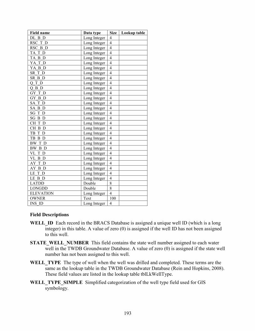
193
Field name Data type Size Lookup table DL_B_D Long Integer 4 RSC_T_D Long Integer 4 RSC_B_D Long Integer 4 TA_T_D Long Integer 4 TA_B_D Long Integer 4 YA_T_D Long Integer 4 YA_B_D Long Integer 4 SR_T_D Long Integer 4 SR_B_D Long Integer 4 Q_T_D Long Integer 4 Q_B_D Long Integer 4 GY_T_D Long Integer 4 GY_B_D Long Integer 4 SA_T_D Long Integer 4 SA_B_D Long Integer 4 SG_T_D Long Integer 4 SG_B_D Long Integer 4 CH_T_D Long Integer 4 CH_B_D Long Integer 4 TB_T_D Long Integer 4 TB_B_D Long Integer 4 BW_T_D Long Integer 4 BW_B_D Long Integer 4 VL_T_D Long Integer 4 VL_B_D Long Integer 4 AY_T_D Long Integer 4 AY_B_D Long Integer 4 LE_T_D Long Integer 4 LE_B_D Long Integer 4 LATDD Double 8 LONGDD Double 8 ELEVATION Long Integer 4 OWNER Text 100 INS_ID Long Integer 4 Field Descriptions WELL_ID Each record in the BRACS Database is assigned a unique well ID (which is a long
integer) in this table. A value of zero (0) is assigned if the well ID has not been assigned to this well.
STATE_WELL_NUMBER This field contains the state well number assigned to each water well in the TWDB Groundwater Database. A value of zero (0) is assigned if the state well number has not been assigned to this well.
WELL_TYPE The type of well when the well was drilled and completed. These terms are the same as the lookup table in the TWDB Groundwater Database (Rein and Hopkins, 2008). These field values are listed in the lookup table tblLkWellType.
WELL_TYPE_SIMPLE Simplified categorization of the well type field used for GIS symbology.
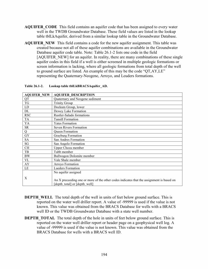
194
AQUIFER_CODE This field contains an aquifer code that has been assigned to every water well in the TWDB Groundwater Database. These field values are listed in the lookup table tblLkAquifer, derived from a similar lookup table in the Groundwater Database.
AQUIFER_NEW This field contains a code for the new aquifer assignment. This table was created because not all of these aquifer combinations are available in the Groundwater Database aquifer code table. Note: Table 26.1-2 lists one code in the field [AQUIFER_NEW] for an aquifer. In reality, there are many combinations of these single aquifer codes in this field if a well is either screened in multiple geologic formations or screen information is lacking, where all geologic formations from total depth of the well to ground surface are listed. An example of this may be the code “QT,AY,LE” representing the Quaternary-Neogene, Arroyo, and Leuders formations.
Table 26.1-2. Lookup table tblLkBRACSAquifer_AD. AQUIFER_NEW AQUIFER_DESCRIPTION QT Quaternary and Neogene sediment TG Trinity Group LD Dockum Group, lower DL Dewey Lake Formation RSC Rustler-Salado formations TA Tansill Formation YA Yates Formation SR Seven Rivers Formation Q Queen Formation GY Grayburg Formation SA San Andres Formation SG San Angelo Formation CH Upper Choza member TB Tubb member BW Bullwagon Dolomite member VL Vale Shale member AY Arroyo Formation LE Lueders Formation
X
No aquifer assigned An X preceeding one or more of the other codes indicates that the assignment is based on [depth_total] or [depth_well]
DEPTH_WELL The total depth of the well in units of feet below ground surface. This is
reported on the water well driller report. A value of -99999 is used if the value is not known. This value was obtained from the BRACS Database for wells with a BRACS well ID or the TWDB Groundwater Database with a state well number.
DEPTH_TOTAL The total depth of the hole in units of feet below ground surface. This is reported on the water well driller report or header page on a geophysical well log. A value of -99999 is used if the value is not known. This value was obtained from the BRACS Database for wells with a BRACS well ID.
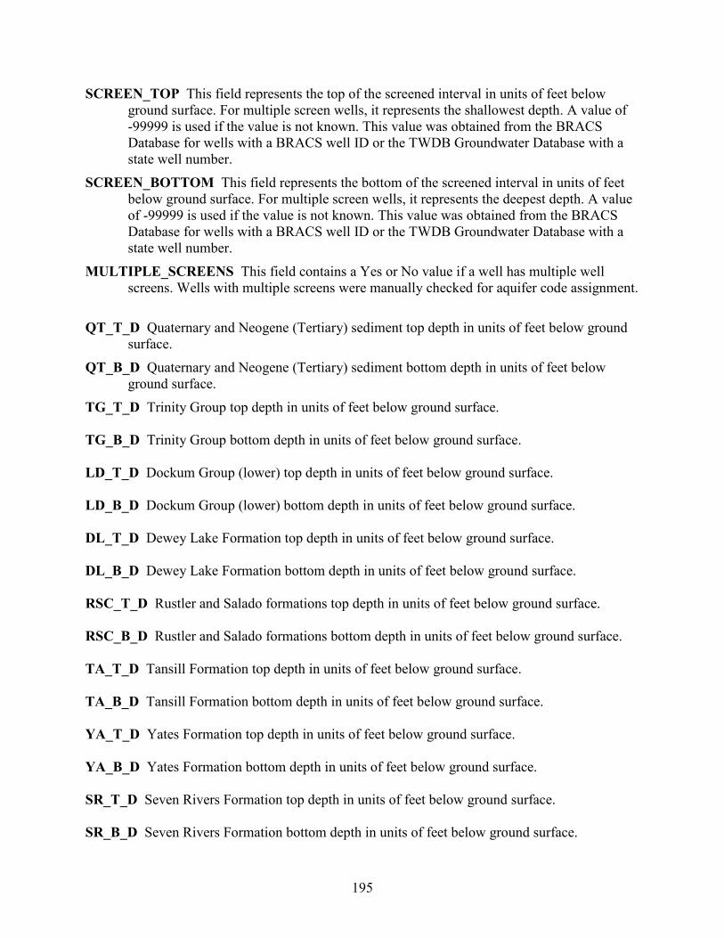
195
SCREEN_TOP This field represents the top of the screened interval in units of feet below ground surface. For multiple screen wells, it represents the shallowest depth. A value of -99999 is used if the value is not known. This value was obtained from the BRACS Database for wells with a BRACS well ID or the TWDB Groundwater Database with a state well number.
SCREEN_BOTTOM This field represents the bottom of the screened interval in units of feet below ground surface. For multiple screen wells, it represents the deepest depth. A value of -99999 is used if the value is not known. This value was obtained from the BRACS Database for wells with a BRACS well ID or the TWDB Groundwater Database with a state well number.
MULTIPLE_SCREENS This field contains a Yes or No value if a well has multiple well screens. Wells with multiple screens were manually checked for aquifer code assignment. QT_T_D Quaternary and Neogene (Tertiary) sediment top depth in units of feet below ground
surface. QT_B_D Quaternary and Neogene (Tertiary) sediment bottom depth in units of feet below
ground surface. TG_T_D Trinity Group top depth in units of feet below ground surface. TG_B_D Trinity Group bottom depth in units of feet below ground surface. LD_T_D Dockum Group (lower) top depth in units of feet below ground surface. LD_B_D Dockum Group (lower) bottom depth in units of feet below ground surface. DL_T_D Dewey Lake Formation top depth in units of feet below ground surface. DL_B_D Dewey Lake Formation bottom depth in units of feet below ground surface. RSC_T_D Rustler and Salado formations top depth in units of feet below ground surface. RSC_B_D Rustler and Salado formations bottom depth in units of feet below ground surface. TA_T_D Tansill Formation top depth in units of feet below ground surface. TA_B_D Tansill Formation bottom depth in units of feet below ground surface. YA_T_D Yates Formation top depth in units of feet below ground surface. YA_B_D Yates Formation bottom depth in units of feet below ground surface. SR_T_D Seven Rivers Formation top depth in units of feet below ground surface. SR_B_D Seven Rivers Formation bottom depth in units of feet below ground surface.
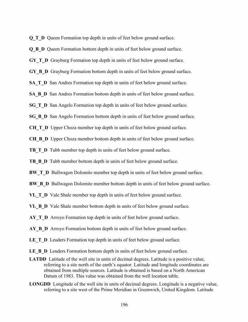
196
Q_T_D Queen Formation top depth in units of feet below ground surface. Q_B_D Queen Formation bottom depth in units of feet below ground surface. GY_T_D Grayburg Formation top depth in units of feet below ground surface. GY_B_D Grayburg Formation bottom depth in units of feet below ground surface. SA_T_D San Andres Formation top depth in units of feet below ground surface. SA_B_D San Andres Formation bottom depth in units of feet below ground surface. SG_T_D San Angelo Formation top depth in units of feet below ground surface. SG_B_D San Angelo Formation bottom depth in units of feet below ground surface. CH_T_D Upper Choza member top depth in units of feet below ground surface. CH_B_D Upper Choza member bottom depth in units of feet below ground surface. TB_T_D Tubb member top depth in units of feet below ground surface. TB_B_D Tubb member bottom depth in units of feet below ground surface. BW_T_D Bullwagon Dolomite member top depth in units of feet below ground surface. BW_B_D Bullwagon Dolomite member bottom depth in units of feet below ground surface. VL_T_D Vale Shale member top depth in units of feet below ground surface. VL_B_D Vale Shale member bottom depth in units of feet below ground surface. AY_T_D Arroyo Formation top depth in units of feet below ground surface. AY_B_D Arroyo Formation bottom depth in units of feet below ground surface. LE_T_D Leuders Formation top depth in units of feet below ground surface. LE_B_D Leuders Formation bottom depth in units of feet below ground surface. LATDD Latitude of the well site in units of decimal degrees. Latitude is a positive value,
referring to a site north of the earth’s equator. Latitude and longitude coordinates are obtained from multiple sources. Latitude is obtained is based on a North American Datum of 1983. This value was obtained from the well location table.
LONGDD Longitude of the well site in units of decimal degrees. Longitude is a negative value, referring to a site west of the Prime Meridian in Greenwich, United Kingdom. Latitude
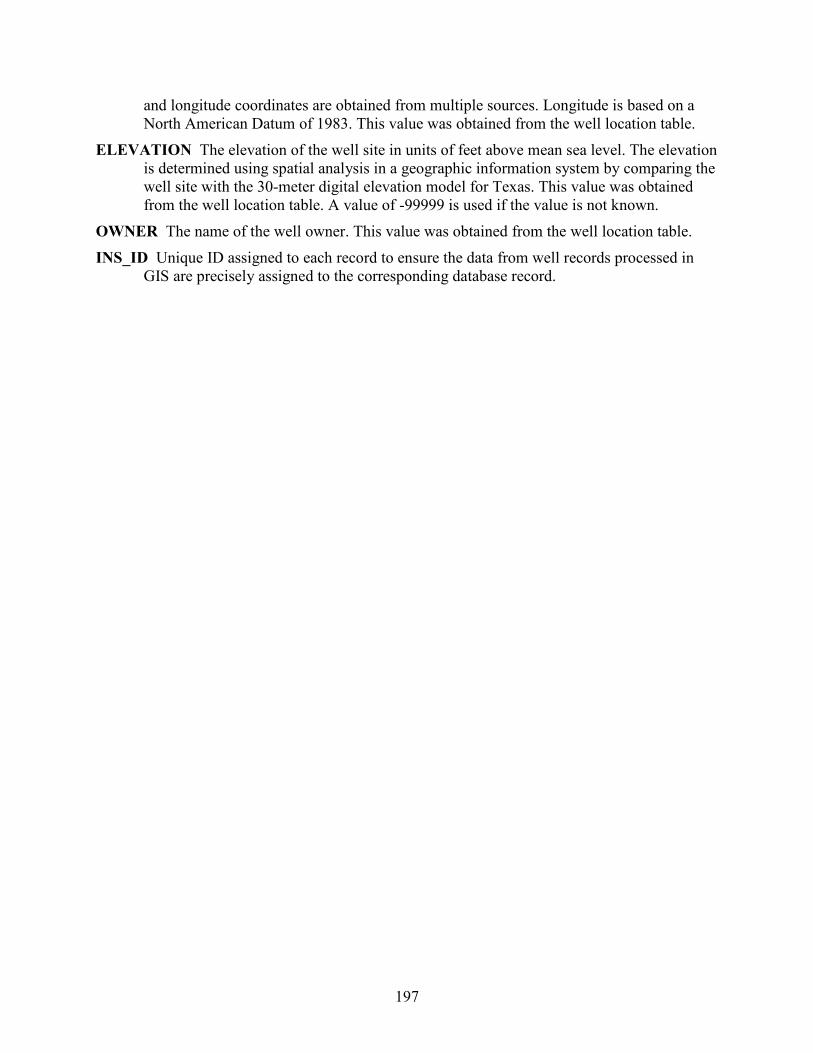
197
and longitude coordinates are obtained from multiple sources. Longitude is based on a North American Datum of 1983. This value was obtained from the well location table.
ELEVATION The elevation of the well site in units of feet above mean sea level. The elevation is determined using spatial analysis in a geographic information system by comparing the well site with the 30-meter digital elevation model for Texas. This value was obtained from the well location table. A value of -99999 is used if the value is not known.
OWNER The name of the well owner. This value was obtained from the well location table. INS_ID Unique ID assigned to each record to ensure the data from well records processed in
GIS are precisely assigned to the corresponding database record.
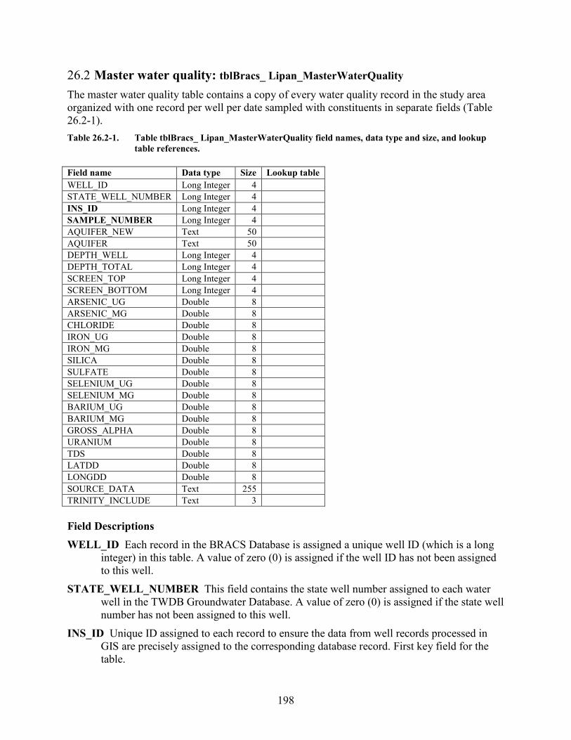
198
26.2 Master water quality: tblBracs_ Lipan_MasterWaterQuality The master water quality table contains a copy of every water quality record in the study area organized with one record per well per date sampled with constituents in separate fields (Table 26.2-1). Table 26.2-1. Table tblBracs_ Lipan_MasterWaterQuality field names, data type and size, and lookup
table references. Field name Data type Size Lookup table WELL_ID Long Integer 4
STATE_WELL_NUMBER Long Integer 4 INS_ID Long Integer 4 SAMPLE_NUMBER Long Integer 4 AQUIFER_NEW Text 50 AQUIFER Text 50 DEPTH_WELL Long Integer 4 DEPTH_TOTAL Long Integer 4 SCREEN_TOP Long Integer 4 SCREEN_BOTTOM Long Integer 4 ARSENIC_UG Double 8 ARSENIC_MG Double 8 CHLORIDE Double 8 IRON_UG Double 8 IRON_MG Double 8 SILICA Double 8 SULFATE Double 8 SELENIUM_UG Double 8 SELENIUM_MG Double 8 BARIUM_UG Double 8 BARIUM_MG Double 8 GROSS_ALPHA Double 8 URANIUM Double 8 TDS Double 8 LATDD Double 8 LONGDD Double 8 SOURCE_DATA Text 255 TRINITY_INCLUDE Text 3 Field Descriptions WELL_ID Each record in the BRACS Database is assigned a unique well ID (which is a long
integer) in this table. A value of zero (0) is assigned if the well ID has not been assigned to this well.
STATE_WELL_NUMBER This field contains the state well number assigned to each water well in the TWDB Groundwater Database. A value of zero (0) is assigned if the state well number has not been assigned to this well.
INS_ID Unique ID assigned to each record to ensure the data from well records processed in GIS are precisely assigned to the corresponding database record. First key field for the table.
199
SAMPLE_NUMBER Second key field for the table. This is an integer for a sample number, since more than one sample may be taken on the same day. It consists of an integer beginning with one for the first record of a well and increases by a value of one for each new record.
AQUIFER_CODE This field contains the aquifer name code that has been assigned to each water well in the TWDB Groundwater Database.
AQUIFER_NEW This field contains a code for the new aquifer assignment. This table was created because not all of these aquifer combinations are available in the Groundwater Database aquifer code table. Note: Table 26-1-2 lists one code in the field [AQUIFER_NEW] for an aquifer. In reality, there are many combinations of these single aquifer codes in this field if a well is either screened in multiple geologic formations or screen information is lacking, where all geologic formations from total depth of the well to ground surface are listed. An example of this may be the code “QT,AY,LE” representing the Quaternary-Neogene, Arroyo, and Leuders formations.
DEPTH_WELL The total depth of the well in units of feet below ground surface. This is reported on the water well driller report. A value of -99999 is used if the value is not known. This value was obtained from the BRACS Database for wells with a BRACS well ID or the TWDB Groundwater Database with a state well number.
DEPTH_TOTAL The total depth of the hole in units of feet below ground surface. This is reported on the water well driller report or header page on a geophysical well log. A value of -99999 is used if the value is not known. This value was obtained from the BRACS Database for wells with a BRACS well ID.
SCREEN_TOP This field represents the top of the screened interval in units of feet below ground surface. For multiple screen wells, it represents the shallowest depth. A value of -99999 is used if the value is not known. This value was obtained from the BRACS Database for wells with a BRACS well ID or the TWDB Groundwater Database with a state well number.
SCREEN_BOTTOM This field represents the bottom of the screened interval in units of feet below ground surface. For multiple screen wells, it represents the deepest depth. A value of -99999 is used if the value is not known. This value was obtained from the BRACS Database for wells with a BRACS well ID or the TWDB Groundwater Database with a state well number.
ARSENIC_UG Dissolved arsenic in units of micrograms per liter. ARSENIC_MG Dissolved arsenic in units of milligrams per liter. CHLORIDE Chloride in units of milligrams per liter. IRON_UG Dissolved iron in units of micrograms per liter. IRON_MG Dissolved iron in units of milligrams per liter. SILICA Silica in units of milligrams per liter. SULFATE Sulfate in units of milligrams per liter. SELENIUM_UG Dissolved selenium in units of micrograms per liter.
200
SELENIUM_MG Dissolved selenium in units of milligrams per liter. BARIUM_UG Dissolved barium in units of micrograms per liter. BARIUM_MG Dissolved barium in units of milligrams per liter. GROSS_ALPHA Gross alpha radiation, total, in units of picocuries per liter. URANIUM Dissolved uranium in units of milligrams per liter. TDS Total dissolved solids in units of milligrams per liter. LATDD Latitude of the well site in units of decimal degrees. Latitude is a positive value,
referring to a site north of the earth’s equator. Latitude and longitude coordinates are obtained from multiple sources. Latitude is obtained is based on a North American Datum of 1983. This value was obtained from the well location table.
LONGDD Longitude of the well site in units of decimal degrees. Longitude is a negative value, referring to a site west of the Prime Meridian in Greenwich, United Kingdom. Latitude and longitude coordinates are obtained from multiple sources. Longitude is based on a North American Datum of 1983. This value was obtained from the well location table.
SOURCE_DATA Source of the water chemistry data in this table. TRINITY_INCLUDE This field contains the value of “Yes” if the Trinity Group is included in
the stratigraphic column.
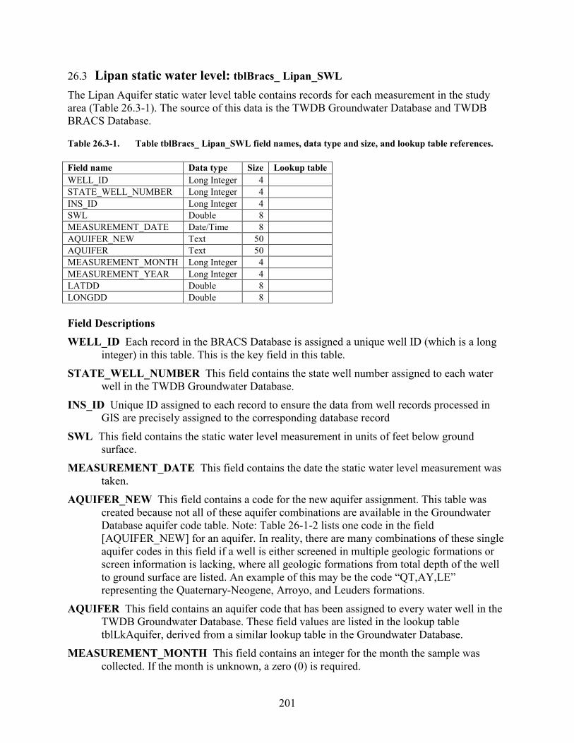
201
26.3 Lipan static water level: tblBracs_ Lipan_SWL
The Lipan Aquifer static water level table contains records for each measurement in the study area (Table 26.3-1). The source of this data is the TWDB Groundwater Database and TWDB BRACS Database. Table 26.3-1. Table tblBracs_ Lipan_SWL field names, data type and size, and lookup table references. Field name Data type Size Lookup table WELL_ID Long Integer 4
STATE_WELL_NUMBER Long Integer 4 INS_ID Long Integer 4 SWL Double 8 MEASUREMENT_DATE Date/Time 8 AQUIFER_NEW Text 50 AQUIFER Text 50 MEASUREMENT_MONTH Long Integer 4 MEASUREMENT_YEAR Long Integer 4 LATDD Double 8 LONGDD Double 8 Field Descriptions WELL_ID Each record in the BRACS Database is assigned a unique well ID (which is a long
integer) in this table. This is the key field in this table. STATE_WELL_NUMBER This field contains the state well number assigned to each water
well in the TWDB Groundwater Database. INS_ID Unique ID assigned to each record to ensure the data from well records processed in
GIS are precisely assigned to the corresponding database record SWL This field contains the static water level measurement in units of feet below ground
surface. MEASUREMENT_DATE This field contains the date the static water level measurement was
taken. AQUIFER_NEW This field contains a code for the new aquifer assignment. This table was
created because not all of these aquifer combinations are available in the Groundwater Database aquifer code table. Note: Table 26-1-2 lists one code in the field [AQUIFER_NEW] for an aquifer. In reality, there are many combinations of these single aquifer codes in this field if a well is either screened in multiple geologic formations or screen information is lacking, where all geologic formations from total depth of the well to ground surface are listed. An example of this may be the code “QT,AY,LE” representing the Quaternary-Neogene, Arroyo, and Leuders formations.
AQUIFER This field contains an aquifer code that has been assigned to every water well in the TWDB Groundwater Database. These field values are listed in the lookup table tblLkAquifer, derived from a similar lookup table in the Groundwater Database.
MEASUREMENT_MONTH This field contains an integer for the month the sample was collected. If the month is unknown, a zero (0) is required.
202
MEASUREMENT_YEAR This field contains an integer for the year the sample was collected.
The year must have four characters. If the year is unknown, a zero (0) is required. LATDD Latitude of the well site in units of decimal degrees. Latitude is a positive value,
referring to a site north of the earth’s equator. Latitude and longitude coordinates are obtained from multiple sources. Latitude is obtained is based on a North American Datum of 1983. A value of zero (0) is used if the latitude is unknown.
LONGDD Longitude of the well site in units of decimal degrees. Longitude is a negative value, referring to a site west of the Prime Meridian in Greenwich, United Kingdom. Latitude and longitude coordinates are obtained from multiple sources. Latitude is obtained is based on a North American Datum of 1983. A value of zero (0) is used if the longitude is unknown.
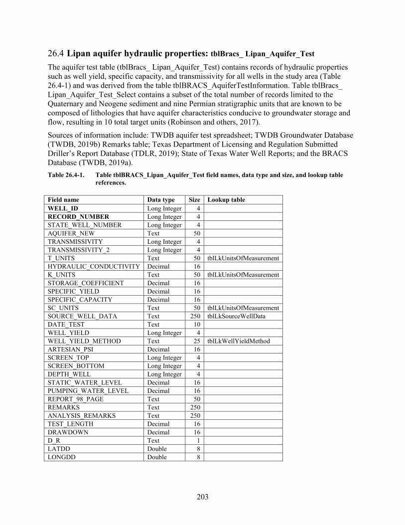
203
26.4 Lipan aquifer hydraulic properties: tblBracs_ Lipan_Aquifer_Test The aquifer test table (tblBracs_ Lipan_Aquifer_Test) contains records of hydraulic properties such as well yield, specific capacity, and transmissivity for all wells in the study area (Table 26.4-1) and was derived from the table tblBRACS_AquiferTestInformation. Table tblBracs_ Lipan_Aquifer_Test_Select contains a subset of the total number of records limited to the Quaternary and Neogene sediment and nine Permian stratigraphic units that are known to be composed of lithologies that have aquifer characteristics conducive to groundwater storage and flow, resulting in 10 total target units (Robinson and others, 2017). Sources of information include: TWDB aquifer test spreadsheet; TWDB Groundwater Database (TWDB, 2019b) Remarks table; Texas Department of Licensing and Regulation Submitted Driller’s Report Database (TDLR, 2019); State of Texas Water Well Reports; and the BRACS Database (TWDB, 2019a). Table 26.4-1. Table tblBRACS_Lipan_Aquifer_Test field names, data type and size, and lookup table
references. Field name Data type Size Lookup table WELL_ID Long Integer 4
RECORD_NUMBER Long Integer 4
STATE_WELL_NUMBER Long Integer 4
AQUIFER_NEW Text 50 TRANSMISSIVITY Long Integer 4
TRANSMISSIVITY_2 Long Integer 4
T_UNITS Text 50 tblLkUnitsOfMeasurement HYDRAULIC_CONDUCTIVITY Decimal 16
K_UNITS Text 50 tblLkUnitsOfMeasurement STORAGE_COEFFICIENT Decimal 16
SPECIFIC_YIELD Decimal 16
SPECIFIC_CAPACITY Decimal 16
SC_UNITS Text 50 tblLkUnitsOfMeasurement SOURCE_WELL_DATA Text 250 tblLkSourceWellData DATE_TEST Text 10
WELL_YIELD Long Integer 4
WELL_YIELD_METHOD Text 25 tblLkWellYieldMethod ARTESIAN_PSI Decimal 16
SCREEN_TOP Long Integer 4
SCREEN_BOTTOM Long Integer 4
DEPTH_WELL Long Integer 4
STATIC_WATER_LEVEL Decimal 16
PUMPING_WATER_LEVEL Decimal 16
REPORT_98_PAGE Text 50
REMARKS Text 250
ANALYSIS_REMARKS Text 250
TEST_LENGTH Decimal 16
DRAWDOWN Decimal 16
D_R Text 1
LATDD Double 8 LONGDD Double 8
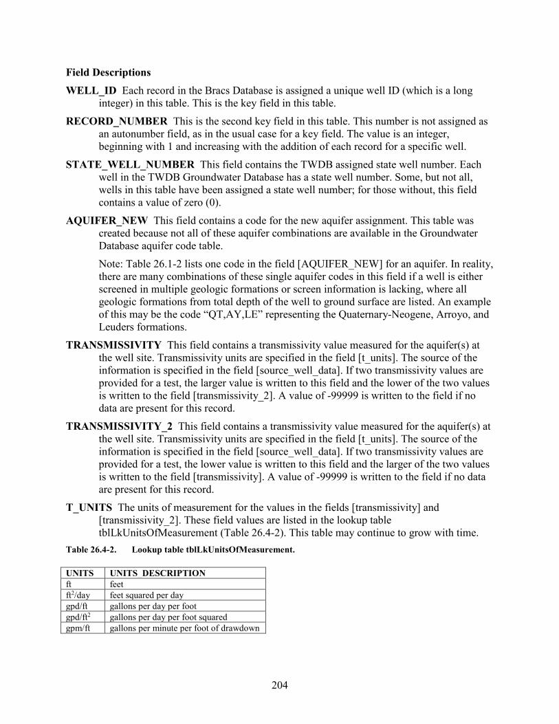
204
Field Descriptions WELL_ID Each record in the Bracs Database is assigned a unique well ID (which is a long
integer) in this table. This is the key field in this table. RECORD_NUMBER This is the second key field in this table. This number is not assigned as
an autonumber field, as in the usual case for a key field. The value is an integer, beginning with 1 and increasing with the addition of each record for a specific well.
STATE_WELL_NUMBER This field contains the TWDB assigned state well number. Each well in the TWDB Groundwater Database has a state well number. Some, but not all, wells in this table have been assigned a state well number; for those without, this field contains a value of zero (0).
AQUIFER_NEW This field contains a code for the new aquifer assignment. This table was created because not all of these aquifer combinations are available in the Groundwater Database aquifer code table. Note: Table 26.1-2 lists one code in the field [AQUIFER_NEW] for an aquifer. In reality, there are many combinations of these single aquifer codes in this field if a well is either screened in multiple geologic formations or screen information is lacking, where all geologic formations from total depth of the well to ground surface are listed. An example of this may be the code “QT,AY,LE” representing the Quaternary-Neogene, Arroyo, and Leuders formations.
TRANSMISSIVITY This field contains a transmissivity value measured for the aquifer(s) at the well site. Transmissivity units are specified in the field [t_units]. The source of the information is specified in the field [source_well_data]. If two transmissivity values are provided for a test, the larger value is written to this field and the lower of the two values is written to the field [transmissivity_2]. A value of -99999 is written to the field if no data are present for this record.
TRANSMISSIVITY_2 This field contains a transmissivity value measured for the aquifer(s) at the well site. Transmissivity units are specified in the field [t_units]. The source of the information is specified in the field [source_well_data]. If two transmissivity values are provided for a test, the lower value is written to this field and the larger of the two values is written to the field [transmissivity]. A value of -99999 is written to the field if no data are present for this record.
T_UNITS The units of measurement for the values in the fields [transmissivity] and [transmissivity_2]. These field values are listed in the lookup table tblLkUnitsOfMeasurement (Table 26.4-2). This table may continue to grow with time.
Table 26.4-2. Lookup table tblLkUnitsOfMeasurement. UNITS UNITS_DESCRIPTION ft feet ft2/day feet squared per day gpd/ft gallons per day per foot gpd/ft2 gallons per day per foot squared gpm/ft gallons per minute per foot of drawdown
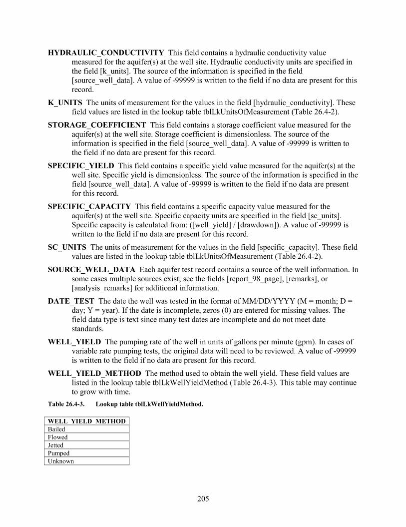
205
HYDRAULIC_CONDUCTIVITY This field contains a hydraulic conductivity value measured for the aquifer(s) at the well site. Hydraulic conductivity units are specified in the field [k_units]. The source of the information is specified in the field [source_well_data]. A value of -99999 is written to the field if no data are present for this record.
K_UNITS The units of measurement for the values in the field [hydraulic_conductivity]. These field values are listed in the lookup table tblLkUnitsOfMeasurement (Table 26.4-2).
STORAGE_COEFFICIENT This field contains a storage coefficient value measured for the aquifer(s) at the well site. Storage coefficient is dimensionless. The source of the information is specified in the field [source_well_data]. A value of -99999 is written to the field if no data are present for this record.
SPECIFIC_YIELD This field contains a specific yield value measured for the aquifer(s) at the well site. Specific yield is dimensionless. The source of the information is specified in the field [source_well_data]. A value of -99999 is written to the field if no data are present for this record.
SPECIFIC_CAPACITY This field contains a specific capacity value measured for the aquifer(s) at the well site. Specific capacity units are specified in the field [sc_units]. Specific capacity is calculated from: ([well_yield] / [drawdown]). A value of -99999 is written to the field if no data are present for this record.
SC_UNITS The units of measurement for the values in the field [specific_capacity]. These field values are listed in the lookup table tblLkUnitsOfMeasurement (Table 26.4-2).
SOURCE_WELL_DATA Each aquifer test record contains a source of the well information. In some cases multiple sources exist; see the fields [report_98_page], [remarks], or [analysis_remarks] for additional information.
DATE_TEST The date the well was tested in the format of MM/DD/YYYY (M = month; D = day; Y = year). If the date is incomplete, zeros (0) are entered for missing values. The field data type is text since many test dates are incomplete and do not meet date standards.
WELL_YIELD The pumping rate of the well in units of gallons per minute (gpm). In cases of variable rate pumping tests, the original data will need to be reviewed. A value of -99999 is written to the field if no data are present for this record.
WELL_YIELD_METHOD The method used to obtain the well yield. These field values are listed in the lookup table tblLkWellYieldMethod (Table 26.4-3). This table may continue to grow with time.
Table 26.4-3. Lookup table tblLkWellYieldMethod. WELL_YIELD_METHOD Bailed Flowed Jetted Pumped Unknown
206
ARTESIAN_PSI The artesian pressure measured at the well head in units of pounds per square inch (psi). If the original value is in units of feet above ground surface, the value is converted to psi using the equation (n · 0.434), where n represents the value units of feet and the conversion factor 0.434 is in units of pounds per square inch per foot.
SCREEN_TOP The top of the well screen interval in units of feet below ground surface. This field is often left blank, since data will be written to the well construction table. If multiple well tests are performed at multiple depths in the well, this field is essential in understanding what part of the aquifer was being evaluated. A value of -99999 is written to the field if no data are present for this record.
SCREEN_BOTTOM The bottom of the well screen interval in units of feet below ground surface. This field is often left blank, since data will be written to the well construction table. If multiple well tests are performed at multiple depths in the well, this field is essential in understanding what part of the aquifer was being evaluated. A value of -99999 is written to the field if no data are present for this record.
DEPTH_WELL The total depth of the well in units of feet below ground surface. This is reported on the water well driller report. A value of -99999 is written to the field if no data are present for this record.
STATIC_WATER_LEVEL The static water level measured at the time of the aquifer test in units of feet below ground surface. This value is negative if the static water level is below the ground surface and positive if above the ground surface (artesian well). A value of -99999 is written to the field if no data are present for this record.
PUMPING_WATER_LEVEL The pumping water level measured at the time of the aquifer test in units of feet below ground surface. This value is negative. A value of -99999 is written to the field if no data are present for this record.
REPORT_98_PAGE This field contains the page number cross-reference to additional data in TWDB Report 98 (Myers, 1969).
REMARKS General remarks pertaining to the aquifer test information. ANALYSIS_REMARKS This field contains remarks about the aquifer test information. Many
references to the original report may be written to this field. The value of R-98 refers to the Myers, 1969 report. Additional references provide the TWDB report number and table number.
TEST_LENGTH The length of the pumping test in units of hours. A value of -99999 is written to the field if no data are present for this record.
DRAWDOWN The drawdown in water level at the end of the aquifer test in units of feet below ground surface. This is a positive value. A value of -99999 is written to the field if no data are present for this record.
D_R This field contains a one-letter code specifying the type of aquifer test performed: D = drawdown test; R = recovery test.
LATDD Latitude of the well site in units of decimal degrees. Latitude is a positive value, referring to a site north of the earth’s equator. Latitude and longitude coordinates are
207
obtained from multiple sources. Latitude is obtained is based on a North American Datum of 1983. This value was obtained from the well location table.
LONGDD Longitude of the well site in units of decimal degrees. Longitude is a negative value, referring to a site west of the Prime Meridian in Greenwich, United Kingdom. Latitude and longitude coordinates are obtained from multiple sources. Longitude is based on a North American Datum of 1983. This value was obtained from the well location table.

208
27. Appendix G: Blossom Aquifer The tables in this appendix were developed for the following Texas Water Development Board BRACS study: Andrews, A.G., and Croskrey, A.D., 2019, Brackish groundwater production zone
recommendation for the Blossom Aquifer, Texas: Texas Water Development Board Open-File Report 19-01, 18 p.
27.1 Aquifer determination: tblAquiferDetermination_Kb This table contains information on which aquifer(s) may be used or penetrated by a well in the study area (Table 27.1-1). Although aquifer codes have been assigned to wells in the Groundwater Database (TWDB, 2019b), it was determined that a systematic assessment of every well in the study area using the 3-dimensional formation top and bottom surfaces with available well screen and well depth data would provide a more accurate and uniform aquifer assignment. Using the new aquifer codes, wells with water quality data could be compared to wells using the same aquifer. The GIS raster surfaces were prepared using the well site elevation of the geologic formation, correction points, and interpolation software. The well site elevation of the geologic formation was then “burned in” to the grid cell. The depth rasters were created from the elevation rasters using the study grid cell elevation file. This process is explained in greater detail in the study report. Every well within the limits of the study area that is in the BRACS Database (TWDB, 2019a) and the Groundwater Database (TWDB, 2019b) was appended to a holding table. This information was imported and geo-referenced in a geographic information system (GIS). The top and bottom of each formation of interest was determined at each well location and the values were written to the holding table. For this study, the geologic formation is the Blossom Sand. Values for the shallowest and deepest screen depths, well depths, and total depth of hole were obtained from TWDB BRACS and Groundwater Database tables. A series of stored queries in Microsoft® Access® was used to determine if a well screen intersected a particular formation. A well may be screened in one or more aquifers. If well screen information was not available, well depth or total depth of hole were used to determine potential aquifers that were penetrated. The procedures used to process all of this information are documented in a TWDB work process document. A value of -99999 is written to elevation and depth fields if data are unknown. Table 27.1-1. Table tblAquiferDetermination_Kb field names, data type and size, and lookup table
references. Field name Data type Size Lookup table WELL_ID Long Integer 4 STATE_WELL_NUMBER Long Integer 4 REGION Long Integer 4 AQUIFER_CODE Text 8 tblLkAquifer AQUIFER_NEW Text 150 tblLkBRACS_Aquifer_AD O_G_WELL_AQ_PENETRATED Text 50 AQ_REASON Text 10
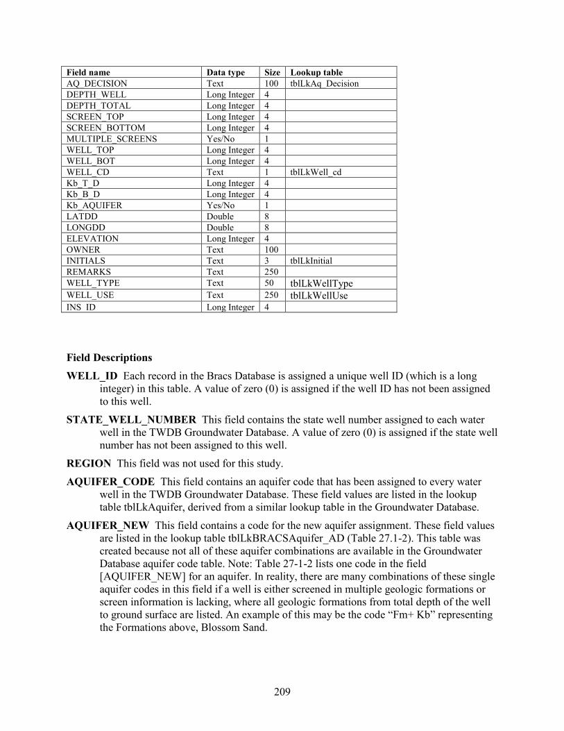
209
Field name Data type Size Lookup table AQ_DECISION Text 100 tblLkAq_Decision DEPTH_WELL Long Integer 4 DEPTH_TOTAL Long Integer 4 SCREEN_TOP Long Integer 4 SCREEN_BOTTOM Long Integer 4 MULTIPLE_SCREENS Yes/No 1 WELL_TOP Long Integer 4 WELL_BOT Long Integer 4 WELL_CD Text 1 tblLkWell_cd Kb_T_D Long Integer 4 Kb_B_D Long Integer 4 Kb_AQUIFER Yes/No 1 LATDD Double 8 LONGDD Double 8 ELEVATION Long Integer 4 OWNER Text 100 INITIALS Text 3 tblLkInitial REMARKS Text 250 WELL_TYPE Text 50 tblLkWellType WELL_USE Text 250 tblLkWellUse INS_ID Long Integer 4 Field Descriptions WELL_ID Each record in the Bracs Database is assigned a unique well ID (which is a long
integer) in this table. A value of zero (0) is assigned if the well ID has not been assigned to this well.
STATE_WELL_NUMBER This field contains the state well number assigned to each water well in the TWDB Groundwater Database. A value of zero (0) is assigned if the state well number has not been assigned to this well.
REGION This field was not used for this study. AQUIFER_CODE This field contains an aquifer code that has been assigned to every water
well in the TWDB Groundwater Database. These field values are listed in the lookup table tblLkAquifer, derived from a similar lookup table in the Groundwater Database.
AQUIFER_NEW This field contains a code for the new aquifer assignment. These field values are listed in the lookup table tblLkBRACSAquifer_AD (Table 27.1-2). This table was created because not all of these aquifer combinations are available in the Groundwater Database aquifer code table. Note: Table 27-1-2 lists one code in the field [AQUIFER_NEW] for an aquifer. In reality, there are many combinations of these single aquifer codes in this field if a well is either screened in multiple geologic formations or screen information is lacking, where all geologic formations from total depth of the well to ground surface are listed. An example of this may be the code “Fm+ Kb” representing the Formations above, Blossom Sand.

210
Table 27.1-2. Lookup table tblLkBRACSAquifer_AD. AQUIFER_NEW AQUIFER_DESCRIPTION Kb Blossom Sand Kn Nacatoch Sand Fm+ Formations above formation of interest Fm- Formations below formation of interest X No aquifer assigned (either because it is not applicable or it is unknown)
O_G_WELL_AQ_PENETRATED This field was not used for this study. AQ_REASON This field contains a code based on the query used to assign a value to the
[aquifer_new] field. The default value of zero (0) is used if the queries did not assign a value. This field is primarily used for internal quality control to ensure the stored queries are operating accurately.
AQ_DECISION This field contains a value of how the aquifer was determined. These field values are listed in the lookup table tblLkAq_Decision (Table 27.1-3).
Table 27.1-3. Lookup table tblLkAq_Decision.
AQ_DECISION Computer analysis of Well Screen (depth) and Aquifer Surfaces (GIS) Geologist Best Professional Judgment of available information. See remarks for more information No Decision Made. Not enough information available DEPTH_WELL The total depth of the well in units of feet below ground surface. This is
reported on the water well driller report. A value of -99999 is used if the value is not known. This value was obtained from the BRACS Database for wells with a BRACS well ID or the TWDB Groundwater Database with a state well number.
DEPTH_TOTAL The total depth of the hole in units of feet below ground surface. This is reported on the water well driller report or header page on a geophysical well log. A value of -99999 is used if the value is not known. This value was obtained from the BRACS Database for wells with a BRACS well ID.
SCREEN_TOP This field represents the top of the screened interval in units of feet below ground surface. For multiple screen wells, it represents the shallowest depth. A value of -99999 is used if the value is not known. This value was obtained from the BRACS Database for wells with a BRACS well ID or the TWDB Groundwater Database with a state well number.
SCREEN_BOTTOM This field represents the bottom of the screened interval in units of feet below ground surface. For multiple screen wells, it represents the deepest depth. A value of -99999 is used if the value is not known. This value was obtained from the BRACS Database for wells with a BRACS well ID or the TWDB Groundwater Database with a state well number.
MULTIPLE_SCREENS This field contains a Yes or No value if a well has multiple well screens. Wells with multiple screens were manually checked for aquifer code assignment.

211
WELL_TOP Top of the open interval for the well. If well screen data are used, this is the top depth of the shallowest screen. If well depth or total depth is used, this value is 0. Units are in feet below ground surface.
WELL_BOT Bottom of the open interval for the well. If well screen data are used, this is the bottom depth of the deepest screen. If well screen data are not available, then either well depth or total depth is used. Units are in feet below ground surface.
WELL_CD This code is assigned to each well record based on the type of data used to compare well construction to formation top and bottom depths. These field values are listed in the lookup table tblLkWell_cd (Table 27.1-4). The precedence of data used for well construction is screen top and bottom, total depth of well, and total depth of hole.
Table 27.1-4. Lookup table tblLkWell_cd.
Kb_T_D Blossom Sand top depth in units of feet below ground surface. Kb_B_D Blossom Sand bottom depth in units of feet below ground surface. Kb_Aquifer This field contains a value of Yes or No based on whether the Blossom Sand is
used by the well. LATDD Latitude of the well site in units of decimal degrees. Latitude is a positive value,
referring to a site north of the earth’s equator. Latitude and longitude coordinates are obtained from multiple sources. Latitude is obtained is based on a North American Datum of 1983. This value was obtained from the well location table.
LONGDD Longitude of the well site in units of decimal degrees. Longitude is a negative value, referring to a site west of the Prime Meridian in Greenwich, United Kingdom. Latitude and longitude coordinates are obtained from multiple sources. Longitude is based on a North American Datum of 1983. This value was obtained from the well location table.
ELEVATION The elevation of the well site in units of feet above mean sea level. The elevation is determined using spatial analysis in a geographic information system by comparing the well site with the 30-meter digital elevation model for Texas. This value was obtained from the well location table. A value of -99999 is used if the value is not known.
OWNER The name of the well owner. This value was obtained from the well location table. INITIALS Initials of person who last edited the record. REMARKS General remarks associated with the well record. WELL_TYPE The type of well when the well was drilled and completed. These terms are the
same as the lookup table in the TWDB Groundwater Database (Rein and Hopkins, 2008). These field values are listed in the lookup table tblLkWellType.
WELL_USE The use of the well generally when the well was drilled and completed. These field values are listed in the lookup table tblLkWellUse. Used to support compliance with
WELL_CD WELL_CD_DESC S Shallowest screen top, deepest screen bottom depths used for aquifer determination analysis T Total hole depth used for aquifer determination analysis W Well depth used for aquifer determination analysis X Not applicable

212
House Bill 30 (84th Texas Legislature; Texas Water Code Chapter 16 §16.060) for determination of water wells used for exclusion in brackish groundwater production zones.
INS_ID Unique ID assigned to each record to ensure the data from well records processed in GIS are precisely assigned to the corresponding database record.
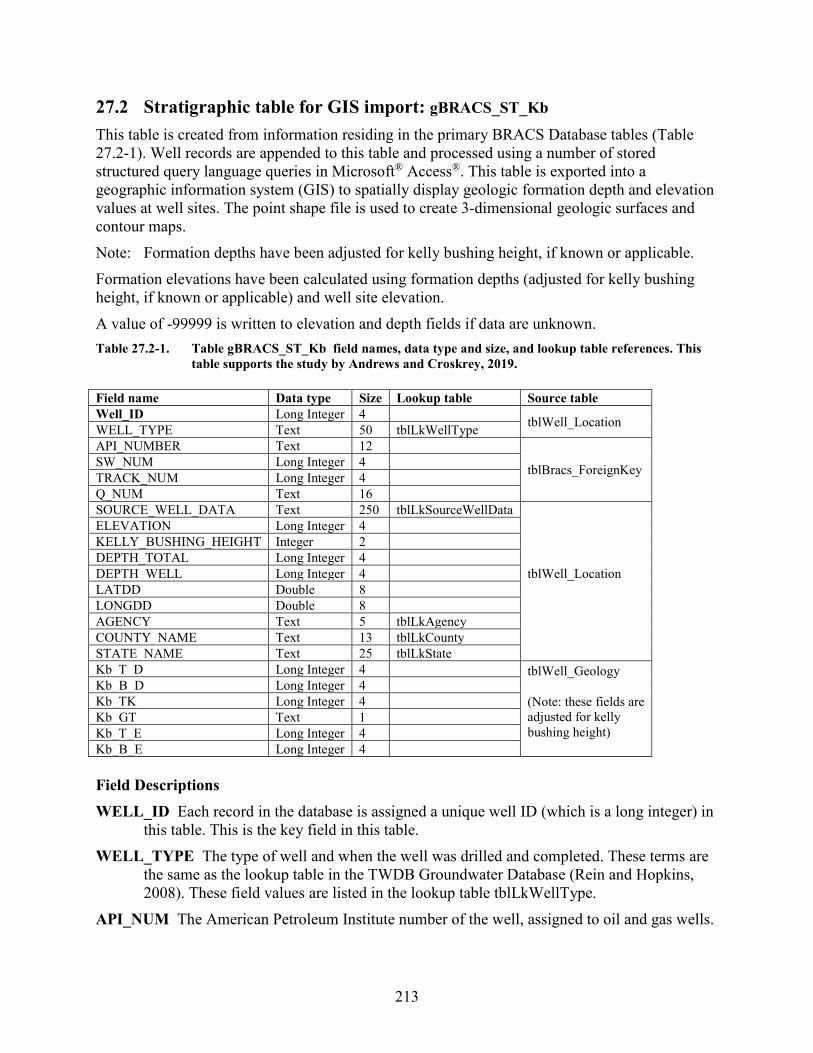
213
27.2 Stratigraphic table for GIS import: gBRACS_ST_Kb This table is created from information residing in the primary BRACS Database tables (Table 27.2-1). Well records are appended to this table and processed using a number of stored structured query language queries in Microsoft® Access®. This table is exported into a geographic information system (GIS) to spatially display geologic formation depth and elevation values at well sites. The point shape file is used to create 3-dimensional geologic surfaces and contour maps. Note: Formation depths have been adjusted for kelly bushing height, if known or applicable. Formation elevations have been calculated using formation depths (adjusted for kelly bushing height, if known or applicable) and well site elevation. A value of -99999 is written to elevation and depth fields if data are unknown. Table 27.2-1. Table gBRACS_ST_Kb field names, data type and size, and lookup table references. This
table supports the study by Andrews and Croskrey, 2019. Field name Data type Size Lookup table Source table Well_ID Long Integer 4 tblWell_Location WELL_TYPE Text 50 tblLkWellType API_NUMBER Text 12
tblBracs_ForeignKey SW_NUM Long Integer 4 TRACK_NUM Long Integer 4 Q_NUM Text 16 SOURCE_WELL_DATA Text 250 tblLkSourceWellData
tblWell_Location
ELEVATION Long Integer 4 KELLY_BUSHING_HEIGHT Integer 2 DEPTH_TOTAL Long Integer 4 DEPTH_WELL Long Integer 4 LATDD Double 8 LONGDD Double 8 AGENCY Text 5 tblLkAgency COUNTY_NAME Text 13 tblLkCounty STATE_NAME Text 25 tblLkState Kb_T_D Long Integer 4 tblWell_Geology
(Note: these fields are adjusted for kelly bushing height)
Kb_B_D Long Integer 4 Kb_TK Long Integer 4 Kb_GT Text 1 Kb_T_E Long Integer 4 Kb_B_E Long Integer 4 Field Descriptions WELL_ID Each record in the database is assigned a unique well ID (which is a long integer) in
this table. This is the key field in this table. WELL_TYPE The type of well and when the well was drilled and completed. These terms are
the same as the lookup table in the TWDB Groundwater Database (Rein and Hopkins, 2008). These field values are listed in the lookup table tblLkWellType.
API_NUM The American Petroleum Institute number of the well, assigned to oil and gas wells.
214
SW_NUM The state well number of the well, assigned to wells in the TWDB Groundwater Database.
TRACK_NUM The track number of the well, assigned to wells in the Texas Department of Licensing and Regulation Submitted Driller Report Database (TDLR, 2019).
WS_NUM The water source code, assigned to wells by the Texas Commission on Environmental Quality public water system program.
Q_NUM The Q number assigned to wells by the Railroad Commission of Texas Groundwater Advisory Unit.
SOURCE_WELL_DATA Each well record is assigned the source of the well information. In some cases multiple sources exist; in this case, the source of the geophysical well log or water well driller report takes precedence. These field values are listed in the lookup table tblLkSourceWellData (Table 2-2).
ELEVATION The elevation of the well site in units of feet above mean sea level. The elevation is determined using spatial analysis in a geographic information system by comparing the well site with the 30-meter digital elevation model for Texas.
KELLY_BUSHING_HEIGHT The height of the drilling rig kelly bushing (KB) used as a measuring point for all subsequent logging. The units are in feet above ground surface. This value is stored as an integer. The term is synonymous with rig floor (RF), derrick floor (DF), rotary table (RT), and drive bushing (DB). This value is usually located on the geophysical well log header page as a unique value, or it must be calculated from the values of elevation of the ground surface and elevation of the kelly bushing. The default value for this field is zero (0) if the measure point of logging is ground surface or if the kelly bushing height is unknown.
DEPTH_TOTAL The total depth of the hole in units of feet below ground surface. This is reported on the water well driller report or header page on a geophysical well log. A value of -99999 is used if the value is not known.
DEPTH_WELL The total depth of the well in units of feet below ground surface. This is reported on the water well driller report. A value of -99999 is used if the value is not known.
LATDD Latitude of the well site in units of decimal degrees. Latitude is a positive value, referring to a site north of the earth’s equator. Latitude and longitude coordinates are obtained from multiple sources. Latitude is obtained is based on a North American Datum of 1983.
LONGDD Longitude of the well site in units of decimal degrees. Longitude is a negative value, referring to a site west of the Prime Meridian in Greenwich, United Kingdom. Latitude and longitude coordinates are obtained from multiple sources. Longitude is based on a North American Datum of 1983.
AGENCY The agency that collected the latitude and longitude coordinates of the well site. These field values are listed in the lookup table tblLkAgency (Table 2-5).
Kb_T_D Blossom Sand top depth in units of feet below ground surface. Kb_B_D Blossom Sand bottom depth in units of feet below ground surface.
215
Kb_TK Blossom Sand thickness in units of feet. Kb_GT Greater than symbol (>) represents well only partially penetrates Blossom Sand. Kb_T_E Blossom Sand top elevation in units of feet above mean sea level. Kb_B_E Blossom Sand bottom elevation in units of feet above mean sea level.
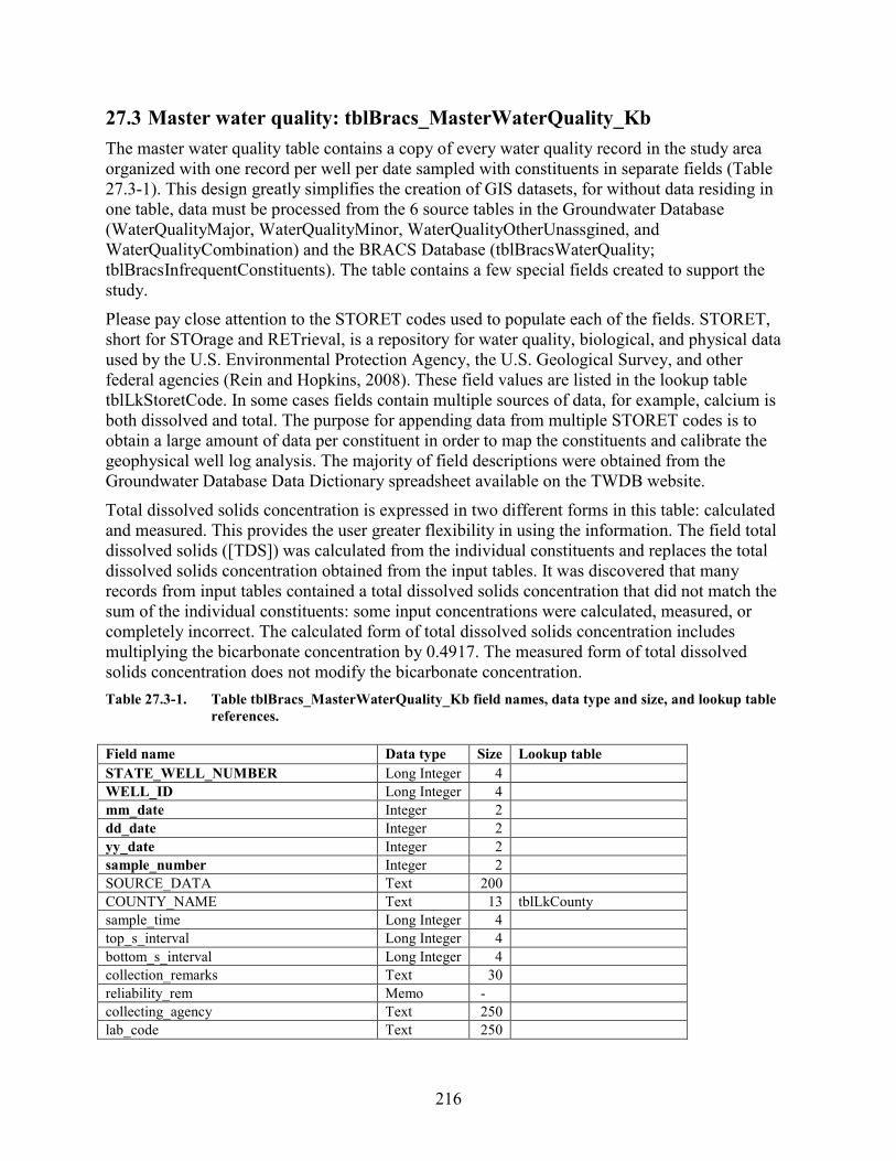
216
27.3 Master water quality: tblBracs_MasterWaterQuality_Kb The master water quality table contains a copy of every water quality record in the study area organized with one record per well per date sampled with constituents in separate fields (Table 27.3-1). This design greatly simplifies the creation of GIS datasets, for without data residing in one table, data must be processed from the 6 source tables in the Groundwater Database (WaterQualityMajor, WaterQualityMinor, WaterQualityOtherUnassgined, and WaterQualityCombination) and the BRACS Database (tblBracsWaterQuality; tblBracsInfrequentConstituents). The table contains a few special fields created to support the study. Please pay close attention to the STORET codes used to populate each of the fields. STORET, short for STOrage and RETrieval, is a repository for water quality, biological, and physical data used by the U.S. Environmental Protection Agency, the U.S. Geological Survey, and other federal agencies (Rein and Hopkins, 2008). These field values are listed in the lookup table tblLkStoretCode. In some cases fields contain multiple sources of data, for example, calcium is both dissolved and total. The purpose for appending data from multiple STORET codes is to obtain a large amount of data per constituent in order to map the constituents and calibrate the geophysical well log analysis. The majority of field descriptions were obtained from the Groundwater Database Data Dictionary spreadsheet available on the TWDB website. Total dissolved solids concentration is expressed in two different forms in this table: calculated and measured. This provides the user greater flexibility in using the information. The field total dissolved solids ([TDS]) was calculated from the individual constituents and replaces the total dissolved solids concentration obtained from the input tables. It was discovered that many records from input tables contained a total dissolved solids concentration that did not match the sum of the individual constituents: some input concentrations were calculated, measured, or completely incorrect. The calculated form of total dissolved solids concentration includes multiplying the bicarbonate concentration by 0.4917. The measured form of total dissolved solids concentration does not modify the bicarbonate concentration. Table 27.3-1. Table tblBracs_MasterWaterQuality_Kb field names, data type and size, and lookup table
references. Field name Data type Size Lookup table STATE_WELL_NUMBER Long Integer 4
WELL_ID Long Integer 4 mm_date Integer 2
dd_date Integer 2
yy_date Integer 2
sample_number Integer 2
SOURCE_DATA Text 200
COUNTY_NAME Text 13 tblLkCounty sample_time Long Integer 4
top_s_interval Long Integer 4
bottom_s_interval Long Integer 4
collection_remarks Text 30
reliability_rem Memo -
collecting_agency Text 250
lab_code Text 250

217
Field name Data type Size Lookup table bu_value Decimal 16 bu_wqanalysis Text 1
silica_flag Text 1
silica Decimal 16
calcium_flag Text 1
calcium Decimal 16
magnesium_flag Text 1
magnesium Decimal 16
sodium_flag Text 1
sodium Decimal 16
potassium_flag Text 1
potassium Decimal 16
strontium_flag Text 1
strontium Decimal 16
carbonate Decimal 16
bicarbonate Decimal 16
sulfate_flag Text 1
sulfate Decimal 16
chloride_flag Text 1
chloride Decimal 16
fluoride_flag Text 1
fluoride Decimal 16
nitrate_flag Text 1
nitrate Decimal 16
pH_flag Text 1
pH Decimal 16
TDS Long Integer 4
TDS_measured Long Integer 4 TDS_RANGE Text 255 tblLkTDS_Range TDS_RNG_NUM Integer 2 tblLkTDS_Range phenophthalein_alkalinity_flag Text 1
phenophthalein_alkalinity Decimal 16
total_alkalinity_flag Text 1
total_alkalinity Decimal 16
spec_cond _flag Text 1
spec_cond Long Integer 4
IRON_FLAG Text 1
IRON Decimal 16
MANGANESE_FLAG Text 1
MANGANESE Decimal 16
ARSENIC_FLAG Text 1 ARSENIC Decimal 16 BORON_FLAG Text 1 BORON Decimal 16 BARIUM_FLAG Text 1 BARIUM Decimal 16 CT Decimal 16
CT_MEASURED Decimal 16 AQUIFER Text 255 AQUIFER_NEW Text 50 tblLkBRACS_Aquifer_AD

218
Field name Data type Size Lookup table NACL_EQUIVALENT_TDS Long Integer 4 NACL_EQUIVALENT_TDS_MEASURED Long Integer 4 NACL_EQ_CF Single 4 NACL_EQ_CF_TDSmeasured Single 4 USGS_UNIQID Long Integer 4 REMARKS Text 250 Field Descriptions STATE_WELL_NUMBER First key field field for the table. This field contains the state well
number assigned to each water well in the TWDB Groundwater Database. If there is no state well number, the value is zero (0).
WELL_ID Second key field for the table. Each record in the database is assigned a unique well ID (which is a long integer) in this table. If there is no well id number, the value is zero (0).
mm_date Third key field for the table. This field contains an integer for the month the sample was collected. If the month is unknown, a zero (0) is required.
dd_date Fourth key field for the table. This field contains an integer for the day the sample was collected. If the day is unknown, a zero (0) is required.
yy_date Fifth key field for the table. This field contains an integer for the year the sample was collected. The year must have four characters. If the year is unknown, enter zero (0).
sample_number Sixth key field for the table. This is an integer for a sample number, since more than one sample may be taken on the same day. It consists of an integer beginning with one for the first record of a well and increases by a value of one for each new record.
SOURCE_DATA This field contains a reference to the source of the information; for example, the report number and table or page number.
COUNTY_NAME The county name based on the well location. These field values are listed in the lookup table tblLkCounty. This lookup table contains state and county names for Texas and adjacent states.
sample_time This field contains the time the sample was collected using four digits in the format of a 24-hour time period (for example, 8:45 a.m. is 0845; 4:21 p.m. is 1621).
top_s_interval Top interval of formation where sample was collected in units of feet below ground surface (only for multiple completion wells).
bottom_s_interval Bottom interval of formation where sample was collected in units of feet below ground surface (only for multiple completion wells).
collection_remarks Remarks about the sample collected. reliability_rem Indicates the process used to collect the sample. collecting_agency Identifies the entity that collected the sample. lab_code Identifies the lab used to analyze the sample. bu_value Value of the balance/unbalanced equation. Units in percent (for example, 3.5).
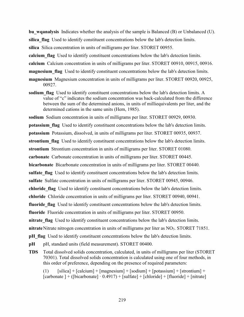
219
bu_wqanalysis Indicates whether the analysis of the sample is Balanced (B) or Unbalanced (U). silica_flag Used to identify constituent concentrations below the lab's detection limits. silica Silica concentration in units of milligrams per liter. STORET 00955. calcium_flag Used to identify constituent concentrations below the lab's detection limits. calcium Calcium concentration in units of milligrams per liter. STORET 00910, 00915, 00916. magnesium_flag Used to identify constituent concentrations below the lab's detection limits. magnesium Magnesium concentration in units of milligrams per liter. STORET 00920, 00925,
00927. sodium_flag Used to identify constituent concentrations below the lab's detection limits. A
value of “c” indicates the sodium concentration was back-calculated from the difference between the sum of the determined anions, in units of milliequivalents per liter, and the determined cations in the same units (Hem, 1985).
sodium Sodium concentration in units of milligrams per liter. STORET 00929, 00930. potassium_flag Used to identify constituent concentrations below the lab's detection limits. potassium Potassium, dissolved, in units of milligrams per liter. STORET 00935, 00937. strontium_flag Used to identify constituent concentrations below the lab's detection limits. strontium Strontium concentration in units of milligrams per liter. STORET 01080. carbonate Carbonate concentration in units of milligrams per liter. STORET 00445. bicarbonate Bicarbonate concentration in units of milligrams per liter. STORET 00440. sulfate_flag Used to identify constituent concentrations below the lab's detection limits. sulfate Sulfate concentration in units of milligrams per liter. STORET 00945, 00946. chloride_flag Used to identify constituent concentrations below the lab's detection limits. chloride Chloride concentration in units of milligrams per liter. STORET 00940, 00941. fluoride_flag Used to identify constituent concentrations below the lab's detection limits. fluoride Fluoride concentration in units of milligrams per liter. STORET 00950. nitrate_flag Used to identify constituent concentrations below the lab's detection limits. nitrate Nitrate nitrogen concentration in units of milligrams per liter as NO3. STORET 71851. pH_flag Used to identify constituent concentrations below the lab's detection limits. pH pH, standard units (field measurement). STORET 00400. TDS Total dissolved solids concentration, calculated, in units of milligrams per liter (STORET
70301). Total dissolved solids concentration is calculated using one of four methods, in this order of preference, depending on the presence of required parameters: (1) [silica] + [calcium] + [magnesium] + [sodium] + [potassium] + [strontium] + [carbonate ] + ([bicarbonate] · 0.4917) + [sulfate] + [chloride] + [fluoride] + [nitrate]
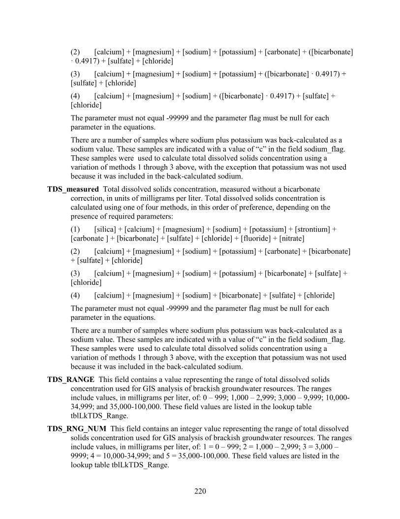
220
(2) [calcium] + [magnesium] + [sodium] + [potassium] + [carbonate] + ([bicarbonate] · 0.4917) + [sulfate] + [chloride] (3) [calcium] + [magnesium] + [sodium] + [potassium] + ([bicarbonate] · 0.4917) + [sulfate] + [chloride] (4) [calcium] + [magnesium] + [sodium] + ([bicarbonate] · 0.4917) + [sulfate] + [chloride]
The parameter must not equal -99999 and the parameter flag must be null for each parameter in the equations.
There are a number of samples where sodium plus potassium was back-calculated as a sodium value. These samples are indicated with a value of “c” in the field sodium_flag. These samples were used to calculate total dissolved solids concentration using a variation of methods 1 through 3 above, with the exception that potassium was not used because it was included in the back-calculated sodium.
TDS_measured Total dissolved solids concentration, measured without a bicarbonate correction, in units of milligrams per liter. Total dissolved solids concentration is calculated using one of four methods, in this order of preference, depending on the presence of required parameters: (1) [silica] + [calcium] + [magnesium] + [sodium] + [potassium] + [strontium] + [carbonate ] + [bicarbonate] + [sulfate] + [chloride] + [fluoride] + [nitrate] (2) [calcium] + [magnesium] + [sodium] + [potassium] + [carbonate] + [bicarbonate] + [sulfate] + [chloride] (3) [calcium] + [magnesium] + [sodium] + [potassium] + [bicarbonate] + [sulfate] + [chloride] (4) [calcium] + [magnesium] + [sodium] + [bicarbonate] + [sulfate] + [chloride]
The parameter must not equal -99999 and the parameter flag must be null for each parameter in the equations. There are a number of samples where sodium plus potassium was back-calculated as a sodium value. These samples are indicated with a value of “c” in the field sodium_flag. These samples were used to calculate total dissolved solids concentration using a variation of methods 1 through 3 above, with the exception that potassium was not used because it was included in the back-calculated sodium.
TDS_RANGE This field contains a value representing the range of total dissolved solids concentration used for GIS analysis of brackish groundwater resources. The ranges include values, in milligrams per liter, of: 0 – 999; 1,000 – 2,999; 3,000 – 9,999; 10,000-34,999; and 35,000-100,000. These field values are listed in the lookup table tblLkTDS_Range.
TDS_RNG_NUM This field contains an integer value representing the range of total dissolved solids concentration used for GIS analysis of brackish groundwater resources. The ranges include values, in milligrams per liter, of: 1 = 0 – 999; 2 = 1,000 – 2,999; 3 = 3,000 – 9999; 4 = 10,000-34,999; and 5 = 35,000-100,000. These field values are listed in the lookup table tblLkTDS_Range.

221
phenophthalein_alkalinity_flag Used to identify constituent concentrations below the lab's detection limits.
phenophthalein_alkalinity Phenophthalein alkalinity. STORET 00415. total_alkalinity_flag Used to identify constituent concentrations below the lab's detection
limits. total_alkalinity Total alkalinity, dissolved (analyzed in lab). STORET 00410. spec_cond_flag Used to identify constituent concentrations below the lab's detection limits. spec_cond Specific conductance in units of microsiemens per centimeter @ 25 degrees Celcius
(field measurement). STORET 00094. IRON_FLAG Used to identify constituent concentrations below the lab's detection limits. IRON Iron concentration in units of milligrams per liter. STORET 01045, 01046. MANGANESE_FLAG Used to identify constituent concentrations below lab detection limits. MANGANESE Manganese concentration in units of milligrams per liter. STORET 01055,
01056. ARSENIC_FLAG Used to identify constituent concentrations below lab detection limits. ARSENIC Arsenic concentration in units of milligrams per liter. STORET 01000, 01002. BORON_FLAG Used to identify constituent concentrations below lab detection limits. BORON Boron concentration in units of milligrams per liter. STORET 01020, 01022. BARIUM_FLAG Used to identify constituent concentrations below lab detection limits. BARIUM Barium concentration in units of milligrams per liter. STORET 01005, 01007. CT Calculated field: ([tds] / [spec_cond]). Used for log analysis of geophysical well logs. CT_Measured Calculated field: ([tds_measured] / [spec_cond]). Used for log analysis of
geophysical well logs. AQUIFER Field contains the aquifer name. Value obtained from the Groundwater Database
table WaterQualityMajor, WaterQualityMinor, WaterQualityOtherUnassgined, or WaterQualityCombination.
AQUIFER_NEW Field containing code for the new aquifer assignment. These field values are listed in the lookup table tblLkBRACSAquifer_AD (Table 27-1-2). The table was created because not all aquifer combinations are available in the Groundwater Database aquifer code table.
NACL_EQUIVALENT_TDS The value in this field was calculated from existing water quality data multiplied by a weighting factor for each ion to calculate a total dissolved solids concentration equivalent to a sodium chloride solution. This value is used for geophysical well log analysis. The weighting factors are based on the lookup table tblLkCf_NaclWeightingMultiplier that was derived from Schlumberger (1979) Chart Gen-8. Note that this value only accounts for calcium, sodium, potassium, magnesium, bicarbonate, carbonate, sulfate, and chloride.
222
NACL_EQUIVALENT_TDS_MEASURED The value in this field was calculated from existing water quality data multiplied by a weighting factor for each ion to calculate a total dissolved solids measured concentration (with no bicarbonate correction) equivalent to a sodium chloride solution. This value is used for geophysical well log analysis. The weighting factors are based on the lookup table tblLkCf_NaclWeightingMultiplier that was derived from Schlumberger (1979) Chart Gen-8. Note that this value only accounts for calcium, sodium, potassium, magnesium, bicarbonate, carbonate, sulfate, and chloride.
NACL_EQ_CF The sodium chloride correction factor is a calculated field: ([TDS] / [NACL_EQUIVALENT_TDS]). The value is used to correct the resistivity of water equivalent in a process to interpret total dissolved solids from geophysical well log analysis. Units are dimensionless.
NACL_EQ_CF_TDSmeasured The sodium chloride correction factor is a calculated field: ([TDS_measured] / [NACL_EQUIVALENT_TDS_measured]). The value is used to correct the resistivity of water equivalent in a process to interpret total dissolved solids from geophysical well log analysis. Units are dimensionless.
USGS_UNIQID Unique id assigned to each produced water sample found within the U.S. Geological Survey Produced Water Database (Blondes and others, 2016). These samples are from the saline water co-produced with oil and gas.
REMARKS General remarks about an analysis.
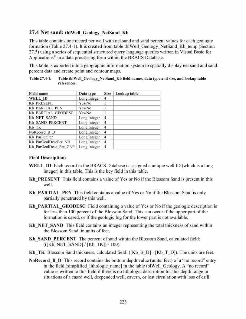
223
27.4 Net sand: tblWell_Geology_NetSand_Kb This table contains one record per well with net sand and sand percent values for each geologic formation (Table 27.4-1). It is created from table tblWell_Geology_NetSand_Kb_temp (Section 27.5) using a series of sequential structured query language queries written in Visual Basic for Applications® in a data processing form within the BRACS Database. This table is exported into a geographic information system to spatially display net sand and sand percent data and create point and contour maps. Table 27.4-1. Table tblWell_Geology_NetSand_Kb field names, data type and size, and lookup table
references. Field name Data type Size Lookup table WELL_ID Long Integer 4 Kb_PRESENT Yes/No 1 Kb_PARTIAL_PEN Yes/No 1 Kb_PARTIAL_GEODESC Yes/No 1 Kb_NET_SAND Long Integer 4 Kb_SAND_PERCENT Long Integer 4 Kb_TK Long Integer 4 NoRecord_B_D Long Integer 4 Kb_ParPenPer Long Integer 4 Kb_ParGeolDescPer_NR Long Integer 4 Kb_ParGeolDesc_Per_GNP Long Integer 4 Field Descriptions WELL_ID Each record in the BRACS Database is assigned a unique well ID (which is a long
integer) in this table. This is the key field in this table. Kb_PRESENT This field contains a value of Yes or No if the Blossom Sand is present in this
well. Kb_PARTIAL_PEN This field contains a value of Yes or No if the Blossom Sand is only
partially penetrated by this well. Kb_PARTIAL_GEODESC Field containing a value of Yes or No if the geologic description is
for less than 100 percent of the Blossom Sand. This can occur if the upper part of the formation is cased, or if the geologic log for the lower part is not available.
Kb_NET_SAND This field contains an integer representing the total thickness of sand within the Blossom Sand, in units of feet.
Kb_SAND_PERCENT The percent of sand within the Blossom Sand, calculated field: (([Kb_NET_SAND] / [Kb_TK]) · 100).
Kb_TK Blossom Sand thickness, calculated field: ([Kb_B_D] - [Kb_T_D]). The units are feet. NoRecord_B_D This record contains the bottom depth value (units: feet) of a “no record” entry
in the field [simplified_lithologic_name] in the table tblWell_Geology. A “no record” value is written to this field if there is no lithologic description for this depth range in situations of a cased well, deepended well, cavern, or lost circulation with loss of drill
224
cuttings returned to surface. This field is used to determine how much of the geologic formation was not defined by lithology for the field [Kb_ParGeolDescPer_NR].
Kb_ParPenPer This field records the percentage of well penetration into the Blossom Sand for wells that only partially penetrate the entire geologic formation. This field is calculated by: ((total depth of well – formation_top depth) / formation thickness) · 100.
Kb_ParGeolDescPer_NR This field records the percentage of missing lithologic data in the Blossom Sand based on the depth of the “no record” value in the field [NoRecord_B_D]. This field is calculated by: ((“no record” bottom depth – formation top depth) / formation thickness) · 100.
Kb_ParGeolDesc_Per_GNP This field records the percentage of missing lithologic data in the Blossom Sand based on a value of either “geology not processed – log image cut off” or “geology not processed, but available on log” (GNP) that are recorded in the field [simplified_lithologic_name] in the table tblWell_Geology and whose depth ranges overlap the Blossom Sand. The field is calculated by one of three equations, based on one of the three common scenarios: (1) entire formation is not described = 100 percent, (2) GNP overlaps the bottom of the formation, ((formation bottom depth – GNP top depth) / formation thickness ·100), or (3) GNP overlaps the top of the formation, ((GNP bottom depth – formation top depth) / formation thickness ·100).
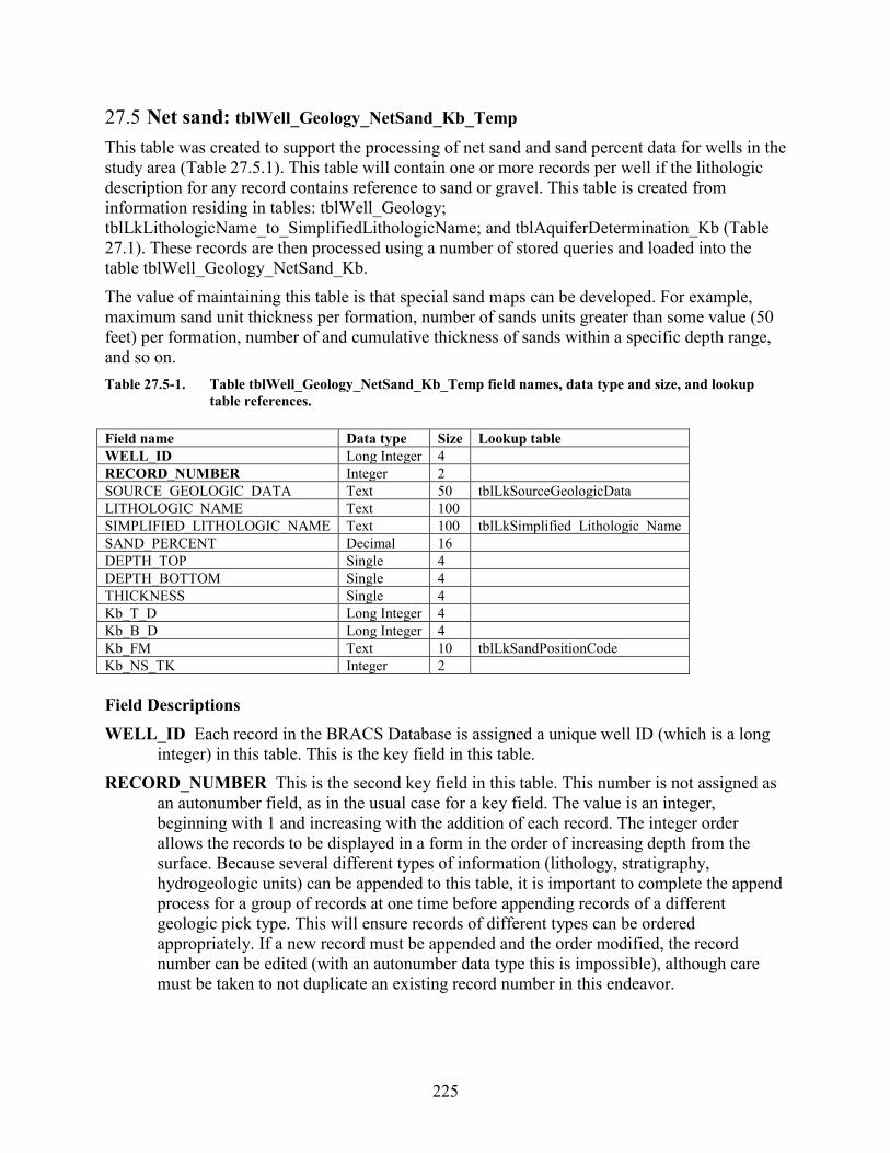
225
27.5 Net sand: tblWell_Geology_NetSand_Kb_Temp This table was created to support the processing of net sand and sand percent data for wells in the study area (Table 27.5.1). This table will contain one or more records per well if the lithologic description for any record contains reference to sand or gravel. This table is created from information residing in tables: tblWell_Geology; tblLkLithologicName_to_SimplifiedLithologicName; and tblAquiferDetermination_Kb (Table 27.1). These records are then processed using a number of stored queries and loaded into the table tblWell_Geology_NetSand_Kb. The value of maintaining this table is that special sand maps can be developed. For example, maximum sand unit thickness per formation, number of sands units greater than some value (50 feet) per formation, number of and cumulative thickness of sands within a specific depth range, and so on. Table 27.5-1. Table tblWell_Geology_NetSand_Kb_Temp field names, data type and size, and lookup
table references. Field name Data type Size Lookup table WELL_ID Long Integer 4 RECORD_NUMBER Integer 2 SOURCE_GEOLOGIC_DATA Text 50 tblLkSourceGeologicData LITHOLOGIC_NAME Text 100 SIMPLIFIED_LITHOLOGIC_NAME Text 100 tblLkSimplified_Lithologic_Name SAND_PERCENT Decimal 16 DEPTH_TOP Single 4 DEPTH_BOTTOM Single 4 THICKNESS Single 4 Kb_T_D Long Integer 4 Kb_B_D Long Integer 4 Kb_FM Text 10 tblLkSandPositionCode Kb_NS_TK Integer 2 Field Descriptions WELL_ID Each record in the BRACS Database is assigned a unique well ID (which is a long
integer) in this table. This is the key field in this table. RECORD_NUMBER This is the second key field in this table. This number is not assigned as
an autonumber field, as in the usual case for a key field. The value is an integer, beginning with 1 and increasing with the addition of each record. The integer order allows the records to be displayed in a form in the order of increasing depth from the surface. Because several different types of information (lithology, stratigraphy, hydrogeologic units) can be appended to this table, it is important to complete the append process for a group of records at one time before appending records of a different geologic pick type. This will ensure records of different types can be ordered appropriately. If a new record must be appended and the order modified, the record number can be edited (with an autonumber data type this is impossible), although care must be taken to not duplicate an existing record number in this endeavor.
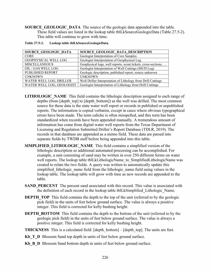
226
SOURCE_GEOLOGIC_DATA The source of the geologic data appended into the table. These field values are listed in the lookup table tblLkSourceGeologicData (Table 27.5-2). This table will continue to grow with time.
Table 27.5-2. Lookup table tblLkSourceGeologicData. SOURCE_GEOLOGIC_DATA SOURCE_GEOLOGIC_DATA_DESCRIPTION CORE Geologist Interpretation of Core Samples GEOPHYSICAL WELL LOG Geologist Interpretation of Geophysical Log MISCELLANEOUS Geophysical logs, well reports, scout tickets, cross-sections, … OIL / GAS WELL LOG Geologist Interpretation of Well Cuttings (MUD Log) PUBLISHED REPORT Geologic description, published report, source unknown UNKNOWN UNKNOWN WATER WELL LOG, DRILLER Well Driller Interpretation of Lithology from Drill Cuttings WATER WELL LOG, GEOLOGIST Geologist Interpretation of Lithology from Drill Cuttings LITHOLOGIC_NAME This field contains the lithologic description assigned to each range of
depths (from [depth_top] to [depth_bottom]) as the well was drilled. The most common source for these data is the state water well report or records in published or unpublished reports. The information is copied verbatim, except in cases where obvious typographical errors have been made. The term caliche is often misspelled, and this term has been standardized when records have been appended manually. A tremendous amount of information has come from digital water well reports from the Texas Department of Licensing and Regulation Submitted Driller’s Report Database (TDLR, 2019). The records in that database are appended as a memo field. These data are parsed into separate fields by TWDB staff before being appended into this table.
SIMPLIFIED_LITHOLOGIC_NAME This field contains a simplified version of the lithologic description so additional automated processing can be accomplished. For example, a unit consisting of sand may be written in over 250 different forms on water well reports. The lookup table tblLkLithologicName_to_SimplifiedLithologicName was created to relate the two fields. A query was written to automatically update this simplified_lithologic_name field from the lithologic_name field using values in the lookup table. The lookup table will grow with time as new records are appended to the table.
SAND_PERCENT The percent sand associated with this record. This value is associated with the definition of each record in the lookup table tblLkSimplified_Lithologic_Name.
DEPTH_TOP This field contains the depth to the top of the unit (referred to by the geologic pick field) in the units of feet below ground surface. The value is always a positive integer. This field is corrected for kelly bushing height.
DEPTH_BOTTOM This field contains the depth to the bottom of the unit (referred to by the geologic pick field) in the units of feet below ground surface. The value is always a positive integer. This field is corrected for kelly bushing height.
THICKNESS This is a calculated field: [depth_bottom] – [depth_top]. The units are feet. Kb_T_D Blossom Sand top depth in units of feet below ground surface. Kb_B_D Blossom Sand bottom depth in units of feet below ground surface.
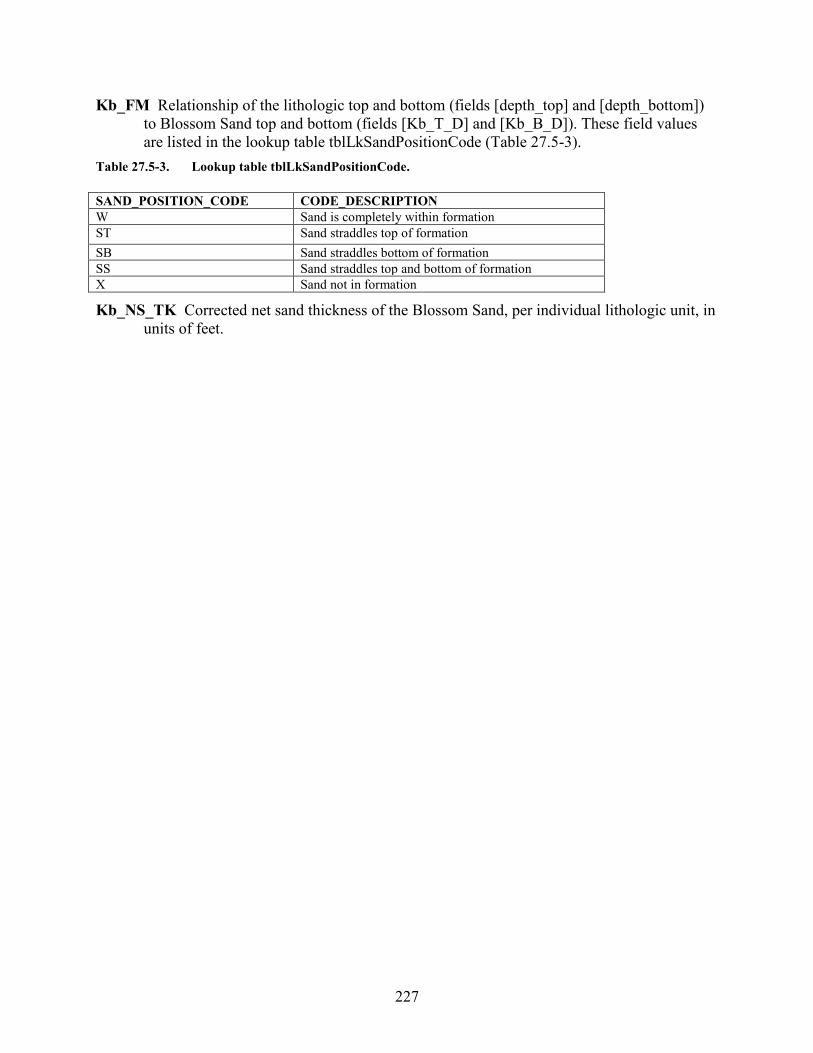
227
Kb_FM Relationship of the lithologic top and bottom (fields [depth_top] and [depth_bottom]) to Blossom Sand top and bottom (fields [Kb_T_D] and [Kb_B_D]). These field values are listed in the lookup table tblLkSandPositionCode (Table 27.5-3).
Table 27.5-3. Lookup table tblLkSandPositionCode. SAND_POSITION_CODE CODE_DESCRIPTION W Sand is completely within formation ST Sand straddles top of formation SB Sand straddles bottom of formation SS Sand straddles top and bottom of formation X Sand not in formation
Kb_NS_TK Corrected net sand thickness of the Blossom Sand, per individual lithologic unit, in units of feet.
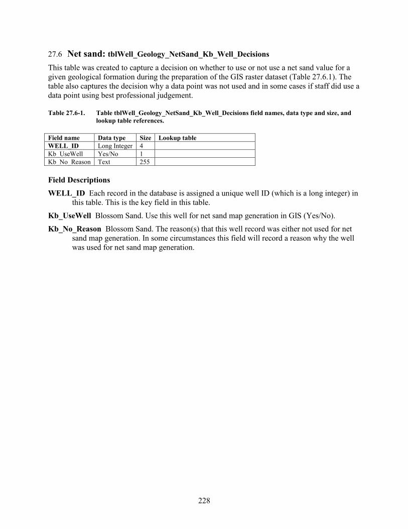
228
27.6 Net sand: tblWell_Geology_NetSand_Kb_Well_Decisions
This table was created to capture a decision on whether to use or not use a net sand value for a given geological formation during the preparation of the GIS raster dataset (Table 27.6.1). The table also captures the decision why a data point was not used and in some cases if staff did use a data point using best professional judgement. Table 27.6-1. Table tblWell_Geology_NetSand_Kb_Well_Decisions field names, data type and size, and
lookup table references. Field name Data type Size Lookup table WELL_ID Long Integer 4 Kb_UseWell Yes/No 1 Kb_No_Reason Text 255 Field Descriptions WELL_ID Each record in the database is assigned a unique well ID (which is a long integer) in
this table. This is the key field in this table. Kb_UseWell Blossom Sand. Use this well for net sand map generation in GIS (Yes/No). Kb_No_Reason Blossom Sand. The reason(s) that this well record was either not used for net
sand map generation. In some circumstances this field will record a reason why the well was used for net sand map generation.
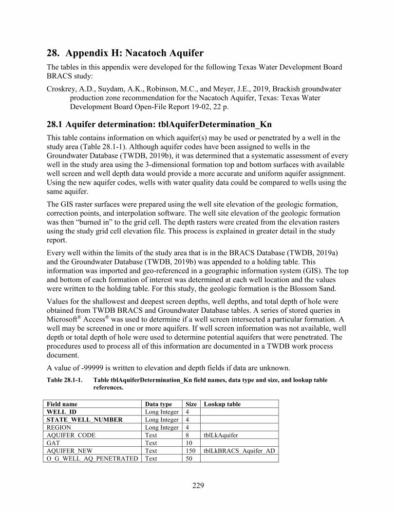
229
28. Appendix H: Nacatoch Aquifer The tables in this appendix were developed for the following Texas Water Development Board BRACS study: Croskrey, A.D., Suydam, A.K., Robinson, M.C., and Meyer, J.E., 2019, Brackish groundwater
production zone recommendation for the Nacatoch Aquifer, Texas: Texas Water Development Board Open-File Report 19-02, 22 p.
28.1 Aquifer determination: tblAquiferDetermination_Kn This table contains information on which aquifer(s) may be used or penetrated by a well in the study area (Table 28.1-1). Although aquifer codes have been assigned to wells in the Groundwater Database (TWDB, 2019b), it was determined that a systematic assessment of every well in the study area using the 3-dimensional formation top and bottom surfaces with available well screen and well depth data would provide a more accurate and uniform aquifer assignment. Using the new aquifer codes, wells with water quality data could be compared to wells using the same aquifer. The GIS raster surfaces were prepared using the well site elevation of the geologic formation, correction points, and interpolation software. The well site elevation of the geologic formation was then “burned in” to the grid cell. The depth rasters were created from the elevation rasters using the study grid cell elevation file. This process is explained in greater detail in the study report. Every well within the limits of the study area that is in the BRACS Database (TWDB, 2019a) and the Groundwater Database (TWDB, 2019b) was appended to a holding table. This information was imported and geo-referenced in a geographic information system (GIS). The top and bottom of each formation of interest was determined at each well location and the values were written to the holding table. For this study, the geologic formation is the Blossom Sand. Values for the shallowest and deepest screen depths, well depths, and total depth of hole were obtained from TWDB BRACS and Groundwater Database tables. A series of stored queries in Microsoft® Access® was used to determine if a well screen intersected a particular formation. A well may be screened in one or more aquifers. If well screen information was not available, well depth or total depth of hole were used to determine potential aquifers that were penetrated. The procedures used to process all of this information are documented in a TWDB work process document. A value of -99999 is written to elevation and depth fields if data are unknown. Table 28.1-1. Table tblAquiferDetermination_Kn field names, data type and size, and lookup table
references. Field name Data type Size Lookup table WELL_ID Long Integer 4 STATE_WELL_NUMBER Long Integer 4 REGION Long Integer 4 AQUIFER_CODE Text 8 tblLkAquifer GAT Text 10 AQUIFER_NEW Text 150 tblLkBRACS_Aquifer_AD O_G_WELL_AQ_PENETRATED Text 50
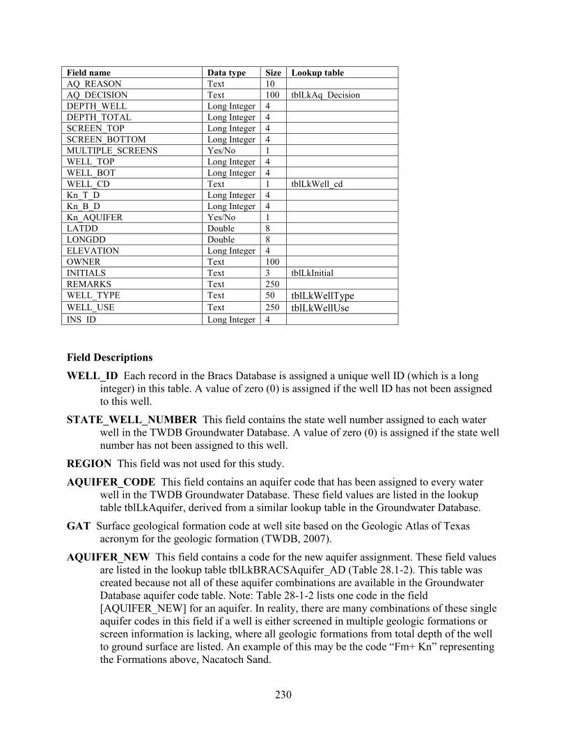
230
Field name Data type Size Lookup table AQ_REASON Text 10 AQ_DECISION Text 100 tblLkAq_Decision DEPTH_WELL Long Integer 4 DEPTH_TOTAL Long Integer 4 SCREEN_TOP Long Integer 4 SCREEN_BOTTOM Long Integer 4 MULTIPLE_SCREENS Yes/No 1 WELL_TOP Long Integer 4 WELL_BOT Long Integer 4 WELL_CD Text 1 tblLkWell_cd Kn_T_D Long Integer 4 Kn_B_D Long Integer 4 Kn_AQUIFER Yes/No 1 LATDD Double 8 LONGDD Double 8 ELEVATION Long Integer 4 OWNER Text 100 INITIALS Text 3 tblLkInitial REMARKS Text 250 WELL_TYPE Text 50 tblLkWellType WELL_USE Text 250 tblLkWellUse INS_ID Long Integer 4 Field Descriptions WELL_ID Each record in the Bracs Database is assigned a unique well ID (which is a long
integer) in this table. A value of zero (0) is assigned if the well ID has not been assigned to this well.
STATE_WELL_NUMBER This field contains the state well number assigned to each water well in the TWDB Groundwater Database. A value of zero (0) is assigned if the state well number has not been assigned to this well.
REGION This field was not used for this study. AQUIFER_CODE This field contains an aquifer code that has been assigned to every water
well in the TWDB Groundwater Database. These field values are listed in the lookup table tblLkAquifer, derived from a similar lookup table in the Groundwater Database.
GAT Surface geological formation code at well site based on the Geologic Atlas of Texas acronym for the geologic formation (TWDB, 2007).
AQUIFER_NEW This field contains a code for the new aquifer assignment. These field values are listed in the lookup table tblLkBRACSAquifer_AD (Table 28.1-2). This table was created because not all of these aquifer combinations are available in the Groundwater Database aquifer code table. Note: Table 28-1-2 lists one code in the field [AQUIFER_NEW] for an aquifer. In reality, there are many combinations of these single aquifer codes in this field if a well is either screened in multiple geologic formations or screen information is lacking, where all geologic formations from total depth of the well to ground surface are listed. An example of this may be the code “Fm+ Kn” representing the Formations above, Nacatoch Sand.
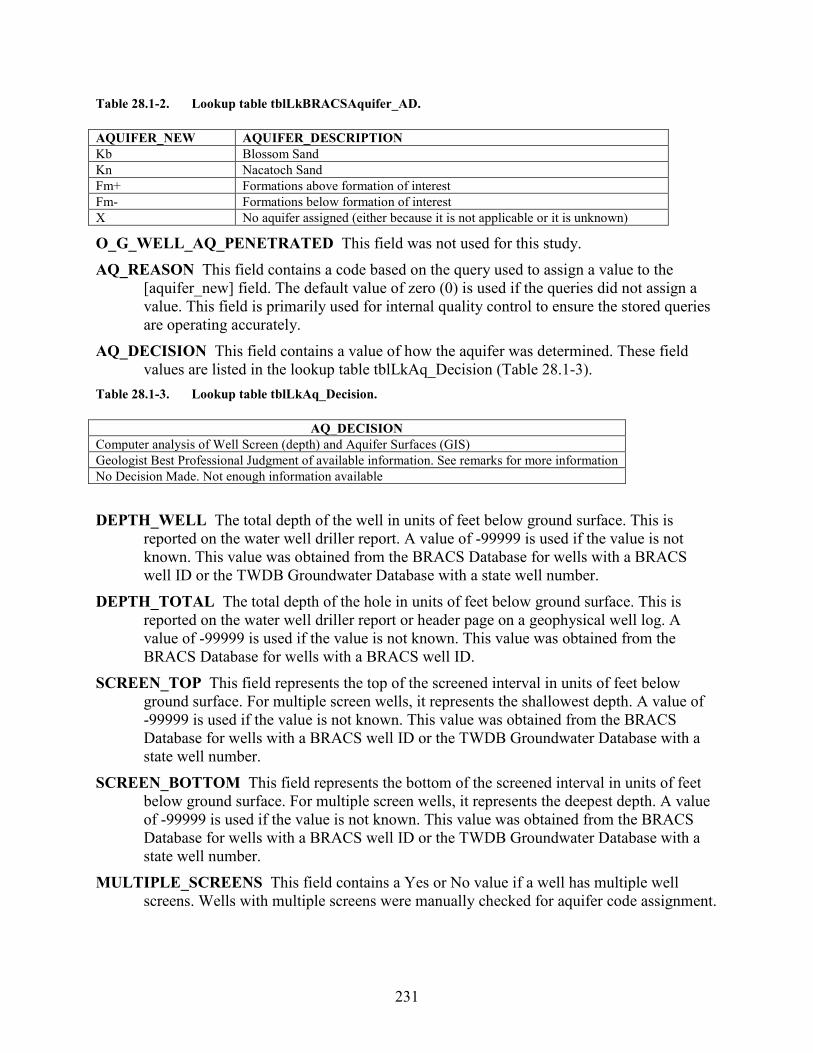
231
Table 28.1-2. Lookup table tblLkBRACSAquifer_AD. AQUIFER_NEW AQUIFER_DESCRIPTION Kb Blossom Sand Kn Nacatoch Sand Fm+ Formations above formation of interest Fm- Formations below formation of interest X No aquifer assigned (either because it is not applicable or it is unknown)
O_G_WELL_AQ_PENETRATED This field was not used for this study. AQ_REASON This field contains a code based on the query used to assign a value to the
[aquifer_new] field. The default value of zero (0) is used if the queries did not assign a value. This field is primarily used for internal quality control to ensure the stored queries are operating accurately.
AQ_DECISION This field contains a value of how the aquifer was determined. These field values are listed in the lookup table tblLkAq_Decision (Table 28.1-3).
Table 28.1-3. Lookup table tblLkAq_Decision.
AQ_DECISION Computer analysis of Well Screen (depth) and Aquifer Surfaces (GIS) Geologist Best Professional Judgment of available information. See remarks for more information No Decision Made. Not enough information available DEPTH_WELL The total depth of the well in units of feet below ground surface. This is
reported on the water well driller report. A value of -99999 is used if the value is not known. This value was obtained from the BRACS Database for wells with a BRACS well ID or the TWDB Groundwater Database with a state well number.
DEPTH_TOTAL The total depth of the hole in units of feet below ground surface. This is reported on the water well driller report or header page on a geophysical well log. A value of -99999 is used if the value is not known. This value was obtained from the BRACS Database for wells with a BRACS well ID.
SCREEN_TOP This field represents the top of the screened interval in units of feet below ground surface. For multiple screen wells, it represents the shallowest depth. A value of -99999 is used if the value is not known. This value was obtained from the BRACS Database for wells with a BRACS well ID or the TWDB Groundwater Database with a state well number.
SCREEN_BOTTOM This field represents the bottom of the screened interval in units of feet below ground surface. For multiple screen wells, it represents the deepest depth. A value of -99999 is used if the value is not known. This value was obtained from the BRACS Database for wells with a BRACS well ID or the TWDB Groundwater Database with a state well number.
MULTIPLE_SCREENS This field contains a Yes or No value if a well has multiple well screens. Wells with multiple screens were manually checked for aquifer code assignment.
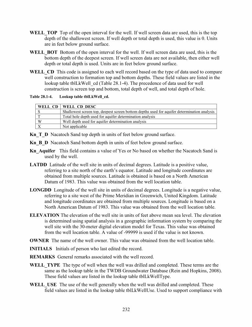
232
WELL_TOP Top of the open interval for the well. If well screen data are used, this is the top depth of the shallowest screen. If well depth or total depth is used, this value is 0. Units are in feet below ground surface.
WELL_BOT Bottom of the open interval for the well. If well screen data are used, this is the bottom depth of the deepest screen. If well screen data are not available, then either well depth or total depth is used. Units are in feet below ground surface.
WELL_CD This code is assigned to each well record based on the type of data used to compare well construction to formation top and bottom depths. These field values are listed in the lookup table tblLkWell_cd (Table 28.1-4). The precedence of data used for well construction is screen top and bottom, total depth of well, and total depth of hole.
Table 28.1-4. Lookup table tblLkWell_cd.
Kn_T_D Nacatoch Sand top depth in units of feet below ground surface. Kn_B_D Nacatoch Sand bottom depth in units of feet below ground surface. Kn_Aquifer This field contains a value of Yes or No based on whether the Nacatoch Sand is
used by the well. LATDD Latitude of the well site in units of decimal degrees. Latitude is a positive value,
referring to a site north of the earth’s equator. Latitude and longitude coordinates are obtained from multiple sources. Latitude is obtained is based on a North American Datum of 1983. This value was obtained from the well location table.
LONGDD Longitude of the well site in units of decimal degrees. Longitude is a negative value, referring to a site west of the Prime Meridian in Greenwich, United Kingdom. Latitude and longitude coordinates are obtained from multiple sources. Longitude is based on a North American Datum of 1983. This value was obtained from the well location table.
ELEVATION The elevation of the well site in units of feet above mean sea level. The elevation is determined using spatial analysis in a geographic information system by comparing the well site with the 30-meter digital elevation model for Texas. This value was obtained from the well location table. A value of -99999 is used if the value is not known.
OWNER The name of the well owner. This value was obtained from the well location table. INITIALS Initials of person who last edited the record. REMARKS General remarks associated with the well record. WELL_TYPE The type of well when the well was drilled and completed. These terms are the
same as the lookup table in the TWDB Groundwater Database (Rein and Hopkins, 2008). These field values are listed in the lookup table tblLkWellType.
WELL_USE The use of the well generally when the well was drilled and completed. These field values are listed in the lookup table tblLkWellUse. Used to support compliance with
WELL_CD WELL_CD_DESC S Shallowest screen top, deepest screen bottom depths used for aquifer determination analysis T Total hole depth used for aquifer determination analysis W Well depth used for aquifer determination analysis X Not applicable

233
House Bill 30 (84th Texas Legislature; Texas Water Code Chapter 16 §16.060) for determination of water wells used for exclusion in brackish groundwater production zones.
INS_ID Unique ID assigned to each record to ensure the data from well records processed in GIS are precisely assigned to the corresponding database record.
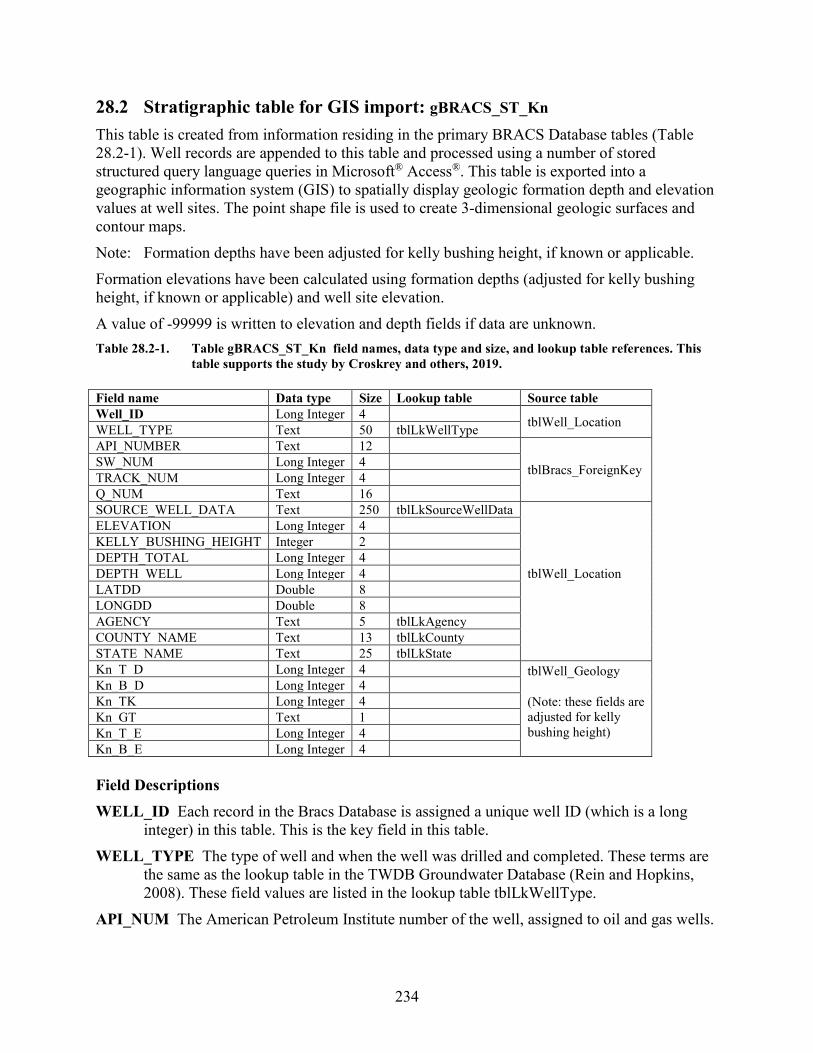
234
28.2 Stratigraphic table for GIS import: gBRACS_ST_Kn This table is created from information residing in the primary BRACS Database tables (Table 28.2-1). Well records are appended to this table and processed using a number of stored structured query language queries in Microsoft® Access®. This table is exported into a geographic information system (GIS) to spatially display geologic formation depth and elevation values at well sites. The point shape file is used to create 3-dimensional geologic surfaces and contour maps. Note: Formation depths have been adjusted for kelly bushing height, if known or applicable. Formation elevations have been calculated using formation depths (adjusted for kelly bushing height, if known or applicable) and well site elevation. A value of -99999 is written to elevation and depth fields if data are unknown. Table 28.2-1. Table gBRACS_ST_Kn field names, data type and size, and lookup table references. This
table supports the study by Croskrey and others, 2019. Field name Data type Size Lookup table Source table Well_ID Long Integer 4 tblWell_Location WELL_TYPE Text 50 tblLkWellType API_NUMBER Text 12
tblBracs_ForeignKey SW_NUM Long Integer 4 TRACK_NUM Long Integer 4 Q_NUM Text 16 SOURCE_WELL_DATA Text 250 tblLkSourceWellData
tblWell_Location
ELEVATION Long Integer 4 KELLY_BUSHING_HEIGHT Integer 2 DEPTH_TOTAL Long Integer 4 DEPTH_WELL Long Integer 4 LATDD Double 8 LONGDD Double 8 AGENCY Text 5 tblLkAgency COUNTY_NAME Text 13 tblLkCounty STATE_NAME Text 25 tblLkState Kn_T_D Long Integer 4 tblWell_Geology
(Note: these fields are adjusted for kelly bushing height)
Kn_B_D Long Integer 4 Kn_TK Long Integer 4 Kn_GT Text 1 Kn_T_E Long Integer 4 Kn_B_E Long Integer 4 Field Descriptions WELL_ID Each record in the Bracs Database is assigned a unique well ID (which is a long
integer) in this table. This is the key field in this table. WELL_TYPE The type of well and when the well was drilled and completed. These terms are
the same as the lookup table in the TWDB Groundwater Database (Rein and Hopkins, 2008). These field values are listed in the lookup table tblLkWellType.
API_NUM The American Petroleum Institute number of the well, assigned to oil and gas wells.

235
SW_NUM The state well number of the well, assigned to wells in the TWDB Groundwater Database.
TRACK_NUM The track number of the well, assigned to wells in the Texas Department of Licensing and Regulation Submitted Driller Report Database (TDLR, 2019).
WS_NUM The water source code, assigned to wells by the Texas Commission on Environmental Quality public water system program.
Q_NUM The Q number assigned to wells by the Railroad Commission of Texas Groundwater Advisory Unit.
SOURCE_WELL_DATA Each well record is assigned the source of the well information. In some cases multiple sources exist; in this case, the source of the geophysical well log or water well driller report takes precedence. These field values are listed in the lookup table tblLkSourceWellData (Table 2-2).
ELEVATION The elevation of the well site in units of feet above mean sea level. The elevation is determined using spatial analysis in a geographic information system by comparing the well site with the 30-meter digital elevation model for Texas.
KELLY_BUSHING_HEIGHT The height of the drilling rig kelly bushing (KB) used as a measuring point for all subsequent logging. The units are in feet above ground surface. This value is stored as an integer. The term is synonymous with rig floor (RF), derrick floor (DF), rotary table (RT), and drive bushing (DB). This value is usually located on the geophysical well log header page as a unique value, or it must be calculated from the values of elevation of the ground surface and elevation of the kelly bushing. The default value for this field is zero (0) if the measure point of logging is ground surface or if the kelly bushing height is unknown.
DEPTH_TOTAL The total depth of the hole in units of feet below ground surface. This is reported on the water well driller report or header page on a geophysical well log. A value of -99999 is used if the value is not known.
DEPTH_WELL The total depth of the well in units of feet below ground surface. This is reported on the water well driller report. A value of -99999 is used if the value is not known.
LATDD Latitude of the well site in units of decimal degrees. Latitude is a positive value, referring to a site north of the earth’s equator. Latitude and longitude coordinates are obtained from multiple sources. Latitude is obtained is based on a North American Datum of 1983.
LONGDD Longitude of the well site in units of decimal degrees. Longitude is a negative value, referring to a site west of the Prime Meridian in Greenwich, United Kingdom. Latitude and longitude coordinates are obtained from multiple sources. Longitude is based on a North American Datum of 1983.
AGENCY The agency that collected the latitude and longitude coordinates of the well site. These field values are listed in the lookup table tblLkAgency (Table 2-5).
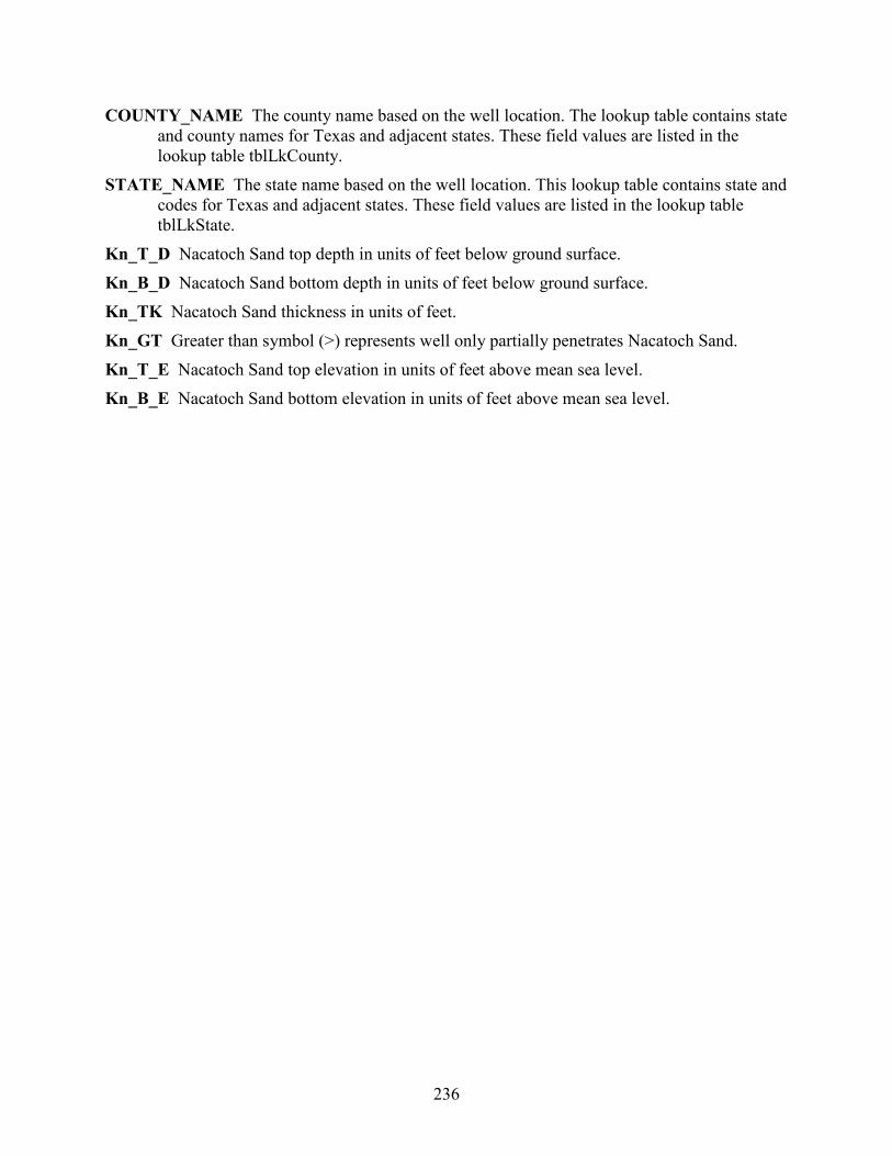
236
COUNTY_NAME The county name based on the well location. The lookup table contains state and county names for Texas and adjacent states. These field values are listed in the lookup table tblLkCounty.
STATE_NAME The state name based on the well location. This lookup table contains state and codes for Texas and adjacent states. These field values are listed in the lookup table tblLkState.
Kn_T_D Nacatoch Sand top depth in units of feet below ground surface. Kn_B_D Nacatoch Sand bottom depth in units of feet below ground surface. Kn_TK Nacatoch Sand thickness in units of feet. Kn_GT Greater than symbol (>) represents well only partially penetrates Nacatoch Sand. Kn_T_E Nacatoch Sand top elevation in units of feet above mean sea level. Kn_B_E Nacatoch Sand bottom elevation in units of feet above mean sea level.

237
28.3 Master water quality: tblBracs_MasterWaterQuality_Kn The master water quality table contains a copy of every water quality record in the study area organized with one record per well per date sampled with constituents in separate fields (Table 28.3-1). This design greatly simplifies the creation of GIS datasets, for without data residing in one table, data must be processed from the 6 source tables in the Groundwater Database (WaterQualityMajor, WaterQualityMinor, WaterQualityOtherUnassgined, and WaterQualityCombination) and the BRACS Database (tblBracsWaterQuality; tblBracsInfrequentConstituents). The table contains a few special fields created to support the study. Please pay close attention to the STORET codes used to populate each of the fields. STORET, short for STOrage and RETrieval, is a repository for water quality, biological, and physical data used by the U.S. Environmental Protection Agency, the U.S. Geological Survey, and other federal agencies (Rein and Hopkins, 2008). These field values are listed in the lookup table tblLkStoretCode. In some cases fields contain multiple sources of data, for example, calcium is both dissolved and total. The purpose for appending data from multiple STORET codes is to obtain a large amount of data per constituent in order to map the constituents and calibrate the geophysical well log analysis. The majority of field descriptions were obtained from the Groundwater Database Data Dictionary spreadsheet available on the TWDB website. Total dissolved solids concentration is expressed in two different forms in this table: calculated and measured. This provides the user greater flexibility in using the information. The field total dissolved solids ([TDS]) was calculated from the individual constituents and replaces the total dissolved solids concentration obtained from the input tables. It was discovered that many records from input tables contained a total dissolved solids concentration that did not match the sum of the individual constituents: some input concentrations were calculated, measured, or completely incorrect. The calculated form of total dissolved solids concentration includes multiplying the bicarbonate concentration by 0.4917. The measured form of total dissolved solids concentration does not modify the bicarbonate concentration. Table 28.3-1. Table tblBracs_MasterWaterQuality_Kn field names, data type and size, and lookup table
references. Field name Data type Size Lookup table STATE_WELL_NUMBER Long Integer 4
WELL_ID Long Integer 4 mm_date Integer 2
dd_date Integer 2
yy_date Integer 2
sample_number Integer 2
SOURCE_DATA Text 200
COUNTY_NAME Text 13 tblLkCounty sample_time Long Integer 4
top_s_interval Long Integer 4
bottom_s_interval Long Integer 4
collection_remarks Text 30
reliability_rem Memo -
collecting_agency Text 250
lab_code Text 250

238
Field name Data type Size Lookup table bu_value Decimal 16 bu_wqanalysis Text 1
silica_flag Text 1
silica Decimal 16
calcium_flag Text 1
calcium Decimal 16
magnesium_flag Text 1
magnesium Decimal 16
sodium_flag Text 1
sodium Decimal 16
potassium_flag Text 1
potassium Decimal 16
strontium_flag Text 1
strontium Decimal 16
carbonate Decimal 16
bicarbonate Decimal 16
sulfate_flag Text 1
sulfate Decimal 16
chloride_flag Text 1
chloride Decimal 16
fluoride_flag Text 1
fluoride Decimal 16
nitrate_flag Text 1
nitrate Decimal 16
pH_flag Text 1
pH Decimal 16
TDS Long Integer 4
TDS_measured Long Integer 4 TDS_RANGE Text 255 tblLkTDS_Range TDS_RNG_NUM Integer 2 tblLkTDS_Range phenophthalein_alkalinity_flag Text 1
phenophthalein_alkalinity Decimal 16
total_alkalinity_flag Text 1
total_alkalinity Decimal 16
spec_cond _flag Text 1
spec_cond Long Integer 4
IRON_FLAG Text 1
IRON Decimal 16
MANGANESE_FLAG Text 1
MANGANESE Decimal 16
ARSENIC_FLAG Text 1 ARSENIC Decimal 16 BORON_FLAG Text 1 BORON Decimal 16 BARIUM_FLAG Text 1 BARIUM Decimal 16 CT Decimal 16
CT_MEASURED Decimal 16 AQUIFER Text 255 AQUIFER_NEW Text 50 tblLkBRACS_Aquifer_AD
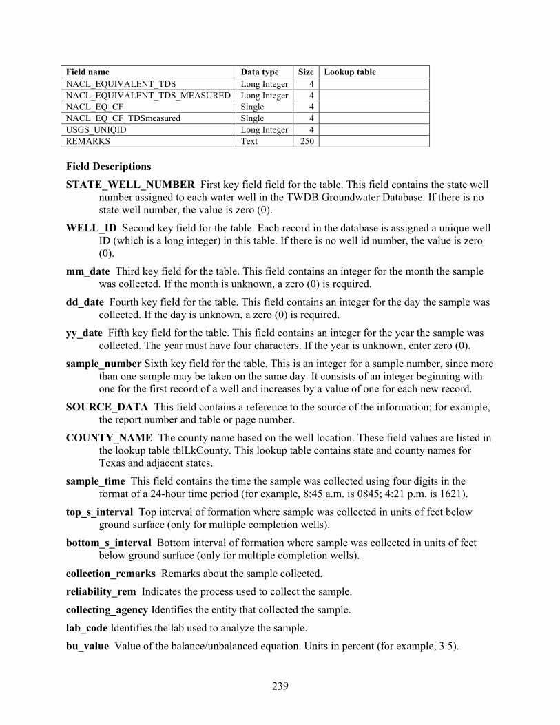
239
Field name Data type Size Lookup table NACL_EQUIVALENT_TDS Long Integer 4 NACL_EQUIVALENT_TDS_MEASURED Long Integer 4 NACL_EQ_CF Single 4 NACL_EQ_CF_TDSmeasured Single 4 USGS_UNIQID Long Integer 4 REMARKS Text 250 Field Descriptions STATE_WELL_NUMBER First key field field for the table. This field contains the state well
number assigned to each water well in the TWDB Groundwater Database. If there is no state well number, the value is zero (0).
WELL_ID Second key field for the table. Each record in the database is assigned a unique well ID (which is a long integer) in this table. If there is no well id number, the value is zero (0).
mm_date Third key field for the table. This field contains an integer for the month the sample was collected. If the month is unknown, a zero (0) is required.
dd_date Fourth key field for the table. This field contains an integer for the day the sample was collected. If the day is unknown, a zero (0) is required.
yy_date Fifth key field for the table. This field contains an integer for the year the sample was collected. The year must have four characters. If the year is unknown, enter zero (0).
sample_number Sixth key field for the table. This is an integer for a sample number, since more than one sample may be taken on the same day. It consists of an integer beginning with one for the first record of a well and increases by a value of one for each new record.
SOURCE_DATA This field contains a reference to the source of the information; for example, the report number and table or page number.
COUNTY_NAME The county name based on the well location. These field values are listed in the lookup table tblLkCounty. This lookup table contains state and county names for Texas and adjacent states.
sample_time This field contains the time the sample was collected using four digits in the format of a 24-hour time period (for example, 8:45 a.m. is 0845; 4:21 p.m. is 1621).
top_s_interval Top interval of formation where sample was collected in units of feet below ground surface (only for multiple completion wells).
bottom_s_interval Bottom interval of formation where sample was collected in units of feet below ground surface (only for multiple completion wells).
collection_remarks Remarks about the sample collected. reliability_rem Indicates the process used to collect the sample. collecting_agency Identifies the entity that collected the sample. lab_code Identifies the lab used to analyze the sample. bu_value Value of the balance/unbalanced equation. Units in percent (for example, 3.5).

240
bu_wqanalysis Indicates whether the analysis of the sample is Balanced (B) or Unbalanced (U). silica_flag Used to identify constituent concentrations below the lab's detection limits. silica Silica concentration in units of milligrams per liter. STORET 00955. calcium_flag Used to identify constituent concentrations below the lab's detection limits. calcium Calcium concentration in units of milligrams per liter. STORET 00910, 00915, 00916. magnesium_flag Used to identify constituent concentrations below the lab's detection limits. magnesium Magnesium concentration in units of milligrams per liter. STORET 00920, 00925,
00927. sodium_flag Used to identify constituent concentrations below the lab's detection limits. A
value of “c” indicates the sodium concentration was back-calculated from the difference between the sum of the determined anions, in units of milliequivalents per liter, and the determined cations in the same units (Hem, 1985).
sodium Sodium concentration in units of milligrams per liter. STORET 00929, 00930. potassium_flag Used to identify constituent concentrations below the lab's detection limits. potassium Potassium, dissolved, in units of milligrams per liter. STORET 00935, 00937. strontium_flag Used to identify constituent concentrations below the lab's detection limits. strontium Strontium concentration in units of milligrams per liter. STORET 01080. carbonate Carbonate concentration in units of milligrams per liter. STORET 00445. bicarbonate Bicarbonate concentration in units of milligrams per liter. STORET 00440. sulfate_flag Used to identify constituent concentrations below the lab's detection limits. sulfate Sulfate concentration in units of milligrams per liter. STORET 00945, 00946. chloride_flag Used to identify constituent concentrations below the lab's detection limits. chloride Chloride concentration in units of milligrams per liter. STORET 00940, 00941. fluoride_flag Used to identify constituent concentrations below the lab's detection limits. fluoride Fluoride concentration in units of milligrams per liter. STORET 00950. nitrate_flag Used to identify constituent concentrations below the lab's detection limits. nitrate Nitrate nitrogen concentration in units of milligrams per liter as NO3. STORET 71851. pH_flag Used to identify constituent concentrations below the lab's detection limits. pH pH, standard units (field measurement). STORET 00400. TDS Total dissolved solids concentration, calculated, in units of milligrams per liter (STORET
70301). Total dissolved solids concentration is calculated using one of four methods, in this order of preference, depending on the presence of required parameters: (1) [silica] + [calcium] + [magnesium] + [sodium] + [potassium] + [strontium] + [carbonate ] + ([bicarbonate] · 0.4917) + [sulfate] + [chloride] + [fluoride] + [nitrate]
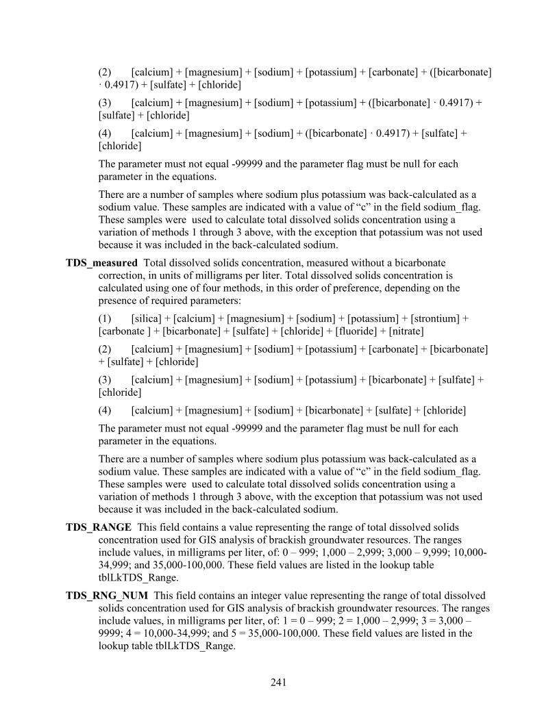
241
(2) [calcium] + [magnesium] + [sodium] + [potassium] + [carbonate] + ([bicarbonate] · 0.4917) + [sulfate] + [chloride] (3) [calcium] + [magnesium] + [sodium] + [potassium] + ([bicarbonate] · 0.4917) + [sulfate] + [chloride] (4) [calcium] + [magnesium] + [sodium] + ([bicarbonate] · 0.4917) + [sulfate] + [chloride]
The parameter must not equal -99999 and the parameter flag must be null for each parameter in the equations.
There are a number of samples where sodium plus potassium was back-calculated as a sodium value. These samples are indicated with a value of “c” in the field sodium_flag. These samples were used to calculate total dissolved solids concentration using a variation of methods 1 through 3 above, with the exception that potassium was not used because it was included in the back-calculated sodium.
TDS_measured Total dissolved solids concentration, measured without a bicarbonate correction, in units of milligrams per liter. Total dissolved solids concentration is calculated using one of four methods, in this order of preference, depending on the presence of required parameters: (1) [silica] + [calcium] + [magnesium] + [sodium] + [potassium] + [strontium] + [carbonate ] + [bicarbonate] + [sulfate] + [chloride] + [fluoride] + [nitrate] (2) [calcium] + [magnesium] + [sodium] + [potassium] + [carbonate] + [bicarbonate] + [sulfate] + [chloride] (3) [calcium] + [magnesium] + [sodium] + [potassium] + [bicarbonate] + [sulfate] + [chloride] (4) [calcium] + [magnesium] + [sodium] + [bicarbonate] + [sulfate] + [chloride]
The parameter must not equal -99999 and the parameter flag must be null for each parameter in the equations. There are a number of samples where sodium plus potassium was back-calculated as a sodium value. These samples are indicated with a value of “c” in the field sodium_flag. These samples were used to calculate total dissolved solids concentration using a variation of methods 1 through 3 above, with the exception that potassium was not used because it was included in the back-calculated sodium.
TDS_RANGE This field contains a value representing the range of total dissolved solids concentration used for GIS analysis of brackish groundwater resources. The ranges include values, in milligrams per liter, of: 0 – 999; 1,000 – 2,999; 3,000 – 9,999; 10,000-34,999; and 35,000-100,000. These field values are listed in the lookup table tblLkTDS_Range.
TDS_RNG_NUM This field contains an integer value representing the range of total dissolved solids concentration used for GIS analysis of brackish groundwater resources. The ranges include values, in milligrams per liter, of: 1 = 0 – 999; 2 = 1,000 – 2,999; 3 = 3,000 – 9999; 4 = 10,000-34,999; and 5 = 35,000-100,000. These field values are listed in the lookup table tblLkTDS_Range.
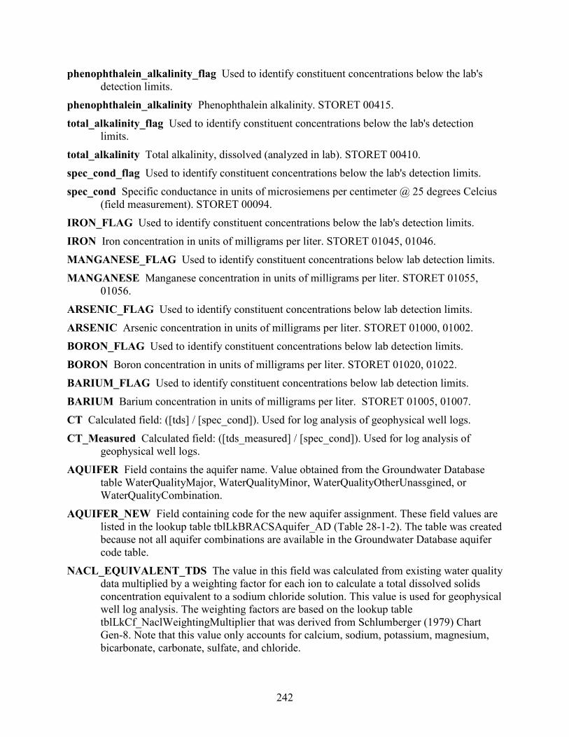
242
phenophthalein_alkalinity_flag Used to identify constituent concentrations below the lab's detection limits.
phenophthalein_alkalinity Phenophthalein alkalinity. STORET 00415. total_alkalinity_flag Used to identify constituent concentrations below the lab's detection
limits. total_alkalinity Total alkalinity, dissolved (analyzed in lab). STORET 00410. spec_cond_flag Used to identify constituent concentrations below the lab's detection limits. spec_cond Specific conductance in units of microsiemens per centimeter @ 25 degrees Celcius
(field measurement). STORET 00094. IRON_FLAG Used to identify constituent concentrations below the lab's detection limits. IRON Iron concentration in units of milligrams per liter. STORET 01045, 01046. MANGANESE_FLAG Used to identify constituent concentrations below lab detection limits. MANGANESE Manganese concentration in units of milligrams per liter. STORET 01055,
01056. ARSENIC_FLAG Used to identify constituent concentrations below lab detection limits. ARSENIC Arsenic concentration in units of milligrams per liter. STORET 01000, 01002. BORON_FLAG Used to identify constituent concentrations below lab detection limits. BORON Boron concentration in units of milligrams per liter. STORET 01020, 01022. BARIUM_FLAG Used to identify constituent concentrations below lab detection limits. BARIUM Barium concentration in units of milligrams per liter. STORET 01005, 01007. CT Calculated field: ([tds] / [spec_cond]). Used for log analysis of geophysical well logs. CT_Measured Calculated field: ([tds_measured] / [spec_cond]). Used for log analysis of
geophysical well logs. AQUIFER Field contains the aquifer name. Value obtained from the Groundwater Database
table WaterQualityMajor, WaterQualityMinor, WaterQualityOtherUnassgined, or WaterQualityCombination.
AQUIFER_NEW Field containing code for the new aquifer assignment. These field values are listed in the lookup table tblLkBRACSAquifer_AD (Table 28-1-2). The table was created because not all aquifer combinations are available in the Groundwater Database aquifer code table.
NACL_EQUIVALENT_TDS The value in this field was calculated from existing water quality data multiplied by a weighting factor for each ion to calculate a total dissolved solids concentration equivalent to a sodium chloride solution. This value is used for geophysical well log analysis. The weighting factors are based on the lookup table tblLkCf_NaclWeightingMultiplier that was derived from Schlumberger (1979) Chart Gen-8. Note that this value only accounts for calcium, sodium, potassium, magnesium, bicarbonate, carbonate, sulfate, and chloride.

243
NACL_EQUIVALENT_TDS_MEASURED The value in this field was calculated from existing water quality data multiplied by a weighting factor for each ion to calculate a total dissolved solids measured concentration (with no bicarbonate correction) equivalent to a sodium chloride solution. This value is used for geophysical well log analysis. The weighting factors are based on the lookup table tblLkCf_NaclWeightingMultiplier that was derived from Schlumberger (1979) Chart Gen-8. Note that this value only accounts for calcium, sodium, potassium, magnesium, bicarbonate, carbonate, sulfate, and chloride.
NACL_EQ_CF The sodium chloride correction factor is a calculated field: ([TDS] / [NACL_EQUIVALENT_TDS]). The value is used to correct the resistivity of water equivalent in a process to interpret total dissolved solids from geophysical well log analysis. Units are dimensionless.
NACL_EQ_CF_TDSmeasured The sodium chloride correction factor is a calculated field: ([TDS_measured] / [NACL_EQUIVALENT_TDS_measured]). The value is used to correct the resistivity of water equivalent in a process to interpret total dissolved solids from geophysical well log analysis. Units are dimensionless.
USGS_UNIQID Unique id assigned to each produced water sample found within the U.S. Geological Survey Produced Water Database (Blondes and others, 2016). These samples are from the saline water co-produced with oil and gas.
REMARKS General remarks about an analysis.

244
28.4 Net sand: tblWell_Geology_NetSand_Kn This table contains one record per well with net sand and sand percent values for each geologic formation (Table 28.4-1). It is created from table tblWell_Geology_NetSand_Kn_temp (Section 28.5) using a series of sequential structured query language queries written in Visual Basic for Applications® in a data processing form within the BRACS Database. This table is exported into a geographic information system to spatially display net sand and sand percent data and create point and contour maps. Table 28.4-1. Table tblWell_Geology_NetSand_Kn field names, data type and size, and lookup table
references. Field name Data type Size Lookup table WELL_ID Long Integer 4 Kn_PRESENT Yes/No 1 Kn_PARTIAL_PEN Yes/No 1 Kn_PARTIAL_GEODESC Yes/No 1 Kn_NET_SAND Long Integer 4 Kn_SAND_PERCENT Long Integer 4 Kn_TK Long Integer 4 NoRecord_B_D Long Integer 4 Kn_ParPenPer Long Integer 4 Kn_ParGeolDescPer_NR Long Integer 4 Kn_ParGeolDesc_Per_GNP Long Integer 4 Field Descriptions WELL_ID Each record in the database is assigned a unique well ID (which is a long integer) in
this table. This is the key field in this table. Kn_PRESENT This field contains a value of Yes or No if the Nacatoch Sand is present in this
well. Kn_PARTIAL_PEN This field contains a value of Yes or No if the Nacatoch Sand is only
partially penetrated by this well. Kn_PARTIAL_GEODESC Field containing a value of Yes or No if the geologic description is
for less than 100 percent of the Nacatoch Sand. This can occur if the upper part of the formation is cased, or if the geologic log for the lower part is not available.
Kn_NET_SAND This field contains an integer representing the total thickness of sand within the Nacatoch Sand, in units of feet.
Kn_SAND_PERCENT The percent of sand within the Nacatoch Sand, calculated field: (([Kb_NET_SAND] / [Kn_TK]) · 100).
Kn_TK Nacatoch Sand thickness, calculated field: ([Kn_B_D] - [Kn_T_D]). The units are feet. NoRecord_B_D This record contains the bottom depth value (units: feet) of a “no record” entry
in the field [simplified_lithologic_name] in the table tblWell_Geology. A “no record” value is written to this field if there is no lithologic description for this depth range in situations of a cased well, deepended well, cavern, or lost circulation with loss of drill
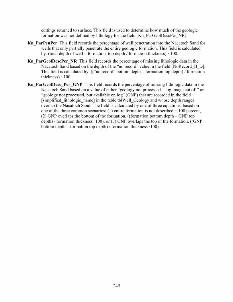
245
cuttings returned to surface. This field is used to determine how much of the geologic formation was not defined by lithology for the field [Kn_ParGeolDescPer_NR].
Kn_ParPenPer This field records the percentage of well penetration into the Nacatoch Sand for wells that only partially penetrate the entire geologic formation. This field is calculated by: (total depth of well – formation_top depth / formation thickness) · 100.
Kn_ParGeolDescPer_NR This field records the percentage of missing lithologic data in the Nacatoch Sand based on the depth of the “no record” value in the field [NoRecord_B_D]. This field is calculated by: ((“no record” bottom depth – formation top depth) / formation thickness) · 100.
Kn_ParGeolDesc_Per_GNP This field records the percentage of missing lithologic data in the Nacatoch Sand based on a value of either “geology not processed – log image cut off” or “geology not processed, but available on log” (GNP) that are recorded in the field [simplified_lithologic_name] in the table tblWell_Geology and whose depth ranges overlap the Nacatoch Sand. The field is calculated by one of three equations, based on one of the three common scenarios: (1) entire formation is not described = 100 percent, (2) GNP overlaps the bottom of the formation, ((formation bottom depth – GNP top depth) / formation thickness ·100), or (3) GNP overlaps the top of the formation, ((GNP bottom depth – formation top depth) / formation thickness ·100).
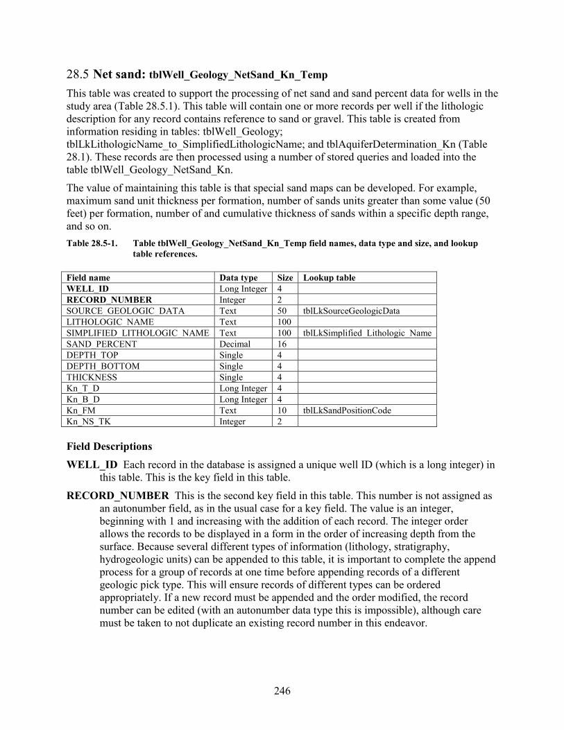
246
28.5 Net sand: tblWell_Geology_NetSand_Kn_Temp This table was created to support the processing of net sand and sand percent data for wells in the study area (Table 28.5.1). This table will contain one or more records per well if the lithologic description for any record contains reference to sand or gravel. This table is created from information residing in tables: tblWell_Geology; tblLkLithologicName_to_SimplifiedLithologicName; and tblAquiferDetermination_Kn (Table 28.1). These records are then processed using a number of stored queries and loaded into the table tblWell_Geology_NetSand_Kn. The value of maintaining this table is that special sand maps can be developed. For example, maximum sand unit thickness per formation, number of sands units greater than some value (50 feet) per formation, number of and cumulative thickness of sands within a specific depth range, and so on. Table 28.5-1. Table tblWell_Geology_NetSand_Kn_Temp field names, data type and size, and lookup
table references. Field name Data type Size Lookup table WELL_ID Long Integer 4 RECORD_NUMBER Integer 2 SOURCE_GEOLOGIC_DATA Text 50 tblLkSourceGeologicData LITHOLOGIC_NAME Text 100 SIMPLIFIED_LITHOLOGIC_NAME Text 100 tblLkSimplified_Lithologic_Name SAND_PERCENT Decimal 16 DEPTH_TOP Single 4 DEPTH_BOTTOM Single 4 THICKNESS Single 4 Kn_T_D Long Integer 4 Kn_B_D Long Integer 4 Kn_FM Text 10 tblLkSandPositionCode Kn_NS_TK Integer 2 Field Descriptions WELL_ID Each record in the database is assigned a unique well ID (which is a long integer) in
this table. This is the key field in this table. RECORD_NUMBER This is the second key field in this table. This number is not assigned as
an autonumber field, as in the usual case for a key field. The value is an integer, beginning with 1 and increasing with the addition of each record. The integer order allows the records to be displayed in a form in the order of increasing depth from the surface. Because several different types of information (lithology, stratigraphy, hydrogeologic units) can be appended to this table, it is important to complete the append process for a group of records at one time before appending records of a different geologic pick type. This will ensure records of different types can be ordered appropriately. If a new record must be appended and the order modified, the record number can be edited (with an autonumber data type this is impossible), although care must be taken to not duplicate an existing record number in this endeavor.

247
SOURCE_GEOLOGIC_DATA The source of the geologic data appended into the table. These field values are listed in the lookup table tblLkSourceGeologicData (Table 28.5-2). This table will continue to grow with time.
Table 28.5-2. Lookup table tblLkSourceGeologicData. SOURCE_GEOLOGIC_DATA SOURCE_GEOLOGIC_DATA_DESCRIPTION CORE Geologist Interpretation of Core Samples GEOPHYSICAL WELL LOG Geologist Interpretation of Geophysical Log MISCELLANEOUS Geophysical logs, well reports, scout tickets, cross-sections, … OIL / GAS WELL LOG Geologist Interpretation of Well Cuttings (MUD Log) PUBLISHED REPORT Geologic description, published report, source unknown UNKNOWN UNKNOWN WATER WELL LOG, DRILLER Well Driller Interpretation of Lithology from Drill Cuttings WATER WELL LOG, GEOLOGIST Geologist Interpretation of Lithology from Drill Cuttings LITHOLOGIC_NAME This field contains the lithologic description assigned to each range of
depths (from [depth_top] to [depth_bottom]) as the well was drilled. The most common source for these data is the state water well report or records in published or unpublished reports. The information is copied verbatim, except in cases where obvious typographical errors have been made. The term caliche is often misspelled, and this term has been standardized when records have been appended manually. A tremendous amount of information has come from digital water well reports from the Texas Department of Licensing and Regulation Submitted Driller’s Report Database (TDLR, 2019). The records in that database are appended as a memo field. These data are parsed into separate fields by TWDB staff before being appended into this table.
SIMPLIFIED_LITHOLOGIC_NAME This field contains a simplified version of the lithologic description so additional automated processing can be accomplished. For example, a unit consisting of sand may be written in over 250 different forms on water well reports. The lookup table tblLkLithologicName_to_SimplifiedLithologicName was created to relate the two fields. A query was written to automatically update this simplified_lithologic_name field from the lithologic_name field using values in the lookup table. The lookup table will grow with time as new records are appended to the table.
SAND_PERCENT The percent sand associated with this record. This value is associated with the definition of each record in the lookup table tblLkSimplified_Lithologic_Name.
DEPTH_TOP This field contains the depth to the top of the unit (referred to by the geologic pick field) in the units of feet below ground surface. The value is always a positive integer. This field is corrected for kelly bushing height.
DEPTH_BOTTOM This field contains the depth to the bottom of the unit (referred to by the geologic pick field) in the units of feet below ground surface. The value is always a positive integer. This field is corrected for kelly bushing height.
THICKNESS This is a calculated field: [depth_bottom] – [depth_top]. The units are feet. Kn_T_D Nacatoch Sand top depth in units of feet below ground surface. Kn_B_D Nacatoch Sand bottom depth in units of feet below ground surface.
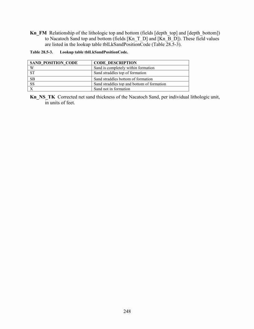
248
Kn_FM Relationship of the lithologic top and bottom (fields [depth_top] and [depth_bottom]) to Nacatoch Sand top and bottom (fields [Kn_T_D] and [Kn_B_D]). These field values are listed in the lookup table tblLkSandPositionCode (Table 28.5-3).
Table 28.5-3. Lookup table tblLkSandPositionCode. SAND_POSITION_CODE CODE_DESCRIPTION W Sand is completely within formation ST Sand straddles top of formation SB Sand straddles bottom of formation SS Sand straddles top and bottom of formation X Sand not in formation
Kn_NS_TK Corrected net sand thickness of the Nacatoch Sand, per individual lithologic unit, in units of feet.

249
28.6 Net sand: tblWell_Geology_NetSand_Kn_Well_Decisions
This table was created to capture a decision on whether to use or not use a net sand value for a given geological formation during the preparation of the GIS raster dataset (Table 28.6.1). The table also captures the decision why a data point was not used and in some cases if staff did use a data point using best professional judgement. Table 28.6-1. Table tblWell_Geology_NetSand_Kn_Well_Decisions field names, data type and size, and
lookup table references. Field name Data type Size Lookup table WELL_ID Long Integer 4 Kn_UseWell Yes/No 1 Kn_No_Reason Text 255 Field Descriptions WELL_ID Each record in the database is assigned a unique well ID (which is a long integer) in
this table. This is the key field in this table. Kn_UseWell Nacatoch Sand. Use this well for net sand map generation in GIS (Yes/No). Kn_No_Reason Nacatoch Sand. The reason(s) that this well record was either not used for net
sand map generation. In some circumstances this field will record a reason why the well was used for net sand map generation.
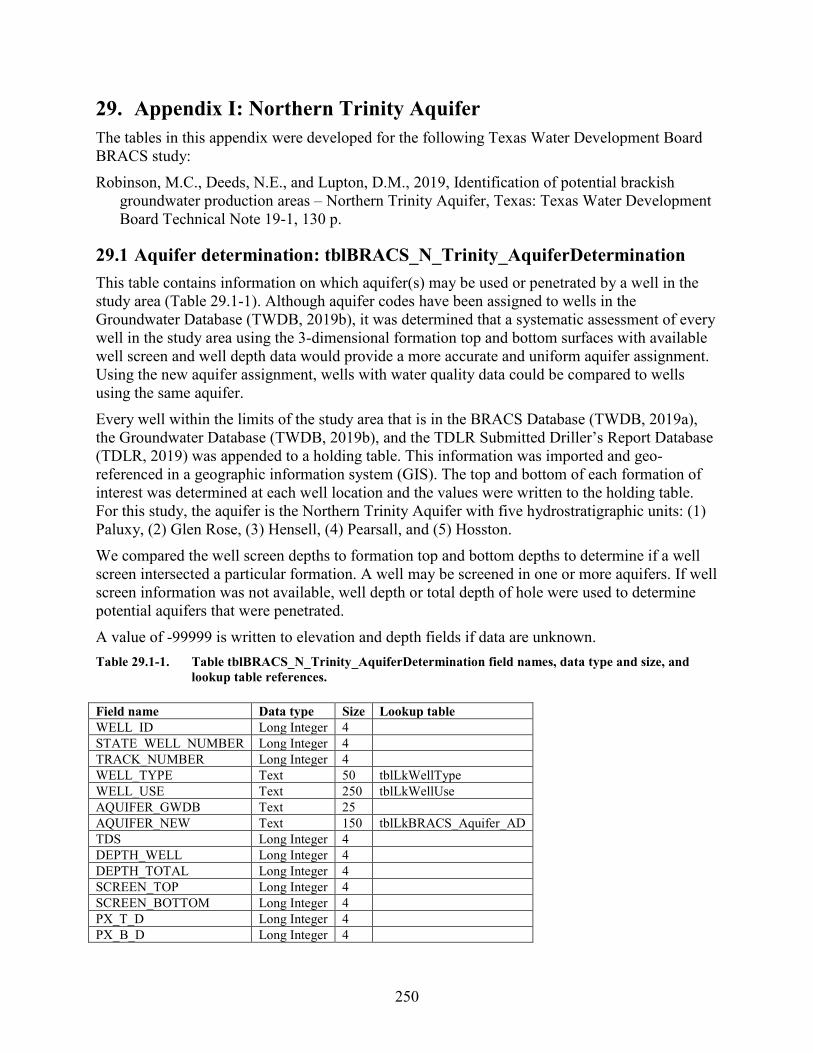
250
29. Appendix I: Northern Trinity Aquifer The tables in this appendix were developed for the following Texas Water Development Board BRACS study: Robinson, M.C., Deeds, N.E., and Lupton, D.M., 2019, Identification of potential brackish
groundwater production areas – Northern Trinity Aquifer, Texas: Texas Water Development Board Technical Note 19-1, 130 p.
29.1 Aquifer determination: tblBRACS_N_Trinity_AquiferDetermination This table contains information on which aquifer(s) may be used or penetrated by a well in the study area (Table 29.1-1). Although aquifer codes have been assigned to wells in the Groundwater Database (TWDB, 2019b), it was determined that a systematic assessment of every well in the study area using the 3-dimensional formation top and bottom surfaces with available well screen and well depth data would provide a more accurate and uniform aquifer assignment. Using the new aquifer assignment, wells with water quality data could be compared to wells using the same aquifer. Every well within the limits of the study area that is in the BRACS Database (TWDB, 2019a), the Groundwater Database (TWDB, 2019b), and the TDLR Submitted Driller’s Report Database (TDLR, 2019) was appended to a holding table. This information was imported and geo-referenced in a geographic information system (GIS). The top and bottom of each formation of interest was determined at each well location and the values were written to the holding table. For this study, the aquifer is the Northern Trinity Aquifer with five hydrostratigraphic units: (1) Paluxy, (2) Glen Rose, (3) Hensell, (4) Pearsall, and (5) Hosston. We compared the well screen depths to formation top and bottom depths to determine if a well screen intersected a particular formation. A well may be screened in one or more aquifers. If well screen information was not available, well depth or total depth of hole were used to determine potential aquifers that were penetrated. A value of -99999 is written to elevation and depth fields if data are unknown. Table 29.1-1. Table tblBRACS_N_Trinity_AquiferDetermination field names, data type and size, and
lookup table references. Field name Data type Size Lookup table WELL_ID Long Integer 4 STATE_WELL_NUMBER Long Integer 4 TRACK_NUMBER Long Integer 4 WELL_TYPE Text 50 tblLkWellType WELL_USE Text 250 tblLkWellUse AQUIFER_GWDB Text 25 AQUIFER_NEW Text 150 tblLkBRACS_Aquifer_AD TDS Long Integer 4 DEPTH_WELL Long Integer 4 DEPTH_TOTAL Long Integer 4 SCREEN_TOP Long Integer 4 SCREEN_BOTTOM Long Integer 4 PX_T_D Long Integer 4 PX_B_D Long Integer 4
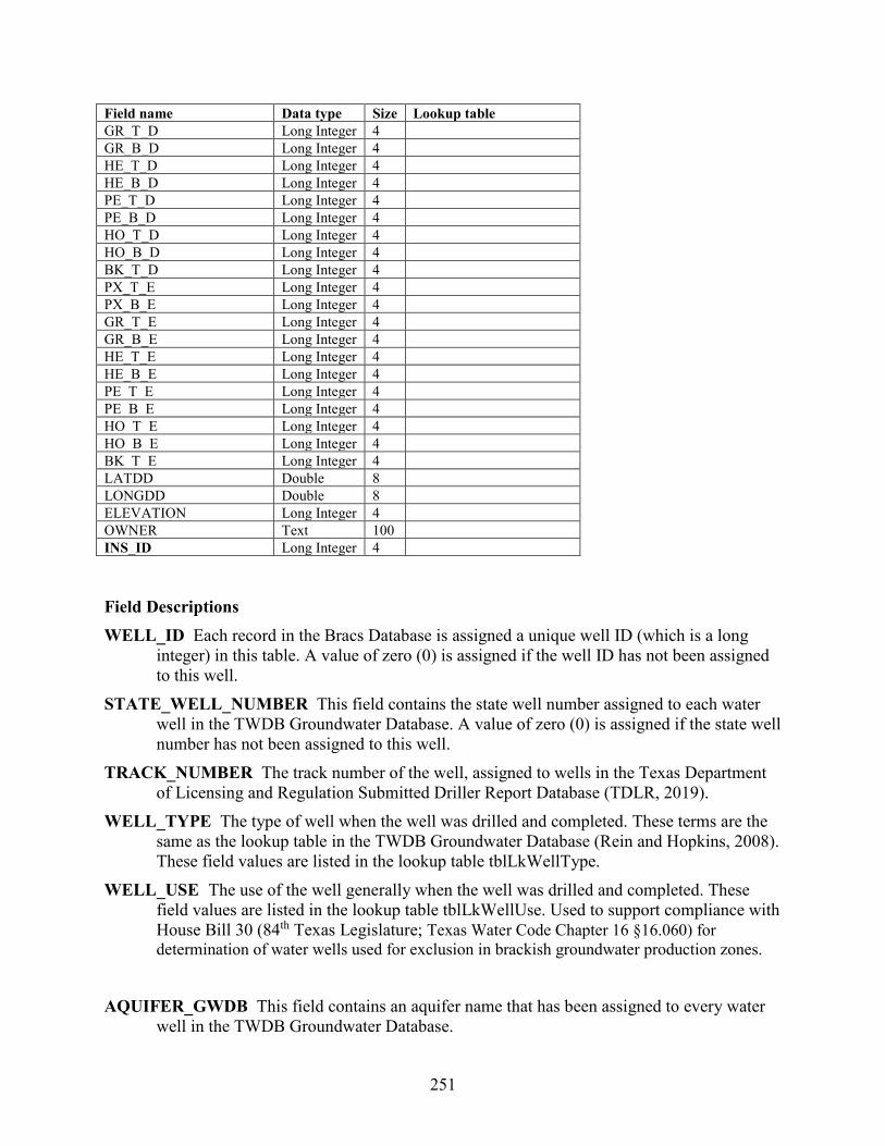
251
Field name Data type Size Lookup table GR_T_D Long Integer 4 GR_B_D Long Integer 4 HE_T_D Long Integer 4 HE_B_D Long Integer 4 PE_T_D Long Integer 4 PE_B_D Long Integer 4 HO_T_D Long Integer 4 HO_B_D Long Integer 4 BK_T_D Long Integer 4 PX_T_E Long Integer 4 PX_B_E Long Integer 4 GR_T_E Long Integer 4 GR_B_E Long Integer 4 HE_T_E Long Integer 4 HE_B_E Long Integer 4 PE_T_E Long Integer 4 PE_B_E Long Integer 4 HO_T_E Long Integer 4 HO_B_E Long Integer 4 BK_T_E Long Integer 4 LATDD Double 8 LONGDD Double 8 ELEVATION Long Integer 4 OWNER Text 100 INS_ID Long Integer 4 Field Descriptions WELL_ID Each record in the Bracs Database is assigned a unique well ID (which is a long
integer) in this table. A value of zero (0) is assigned if the well ID has not been assigned to this well.
STATE_WELL_NUMBER This field contains the state well number assigned to each water well in the TWDB Groundwater Database. A value of zero (0) is assigned if the state well number has not been assigned to this well.
TRACK_NUMBER The track number of the well, assigned to wells in the Texas Department of Licensing and Regulation Submitted Driller Report Database (TDLR, 2019).
WELL_TYPE The type of well when the well was drilled and completed. These terms are the same as the lookup table in the TWDB Groundwater Database (Rein and Hopkins, 2008). These field values are listed in the lookup table tblLkWellType.
WELL_USE The use of the well generally when the well was drilled and completed. These field values are listed in the lookup table tblLkWellUse. Used to support compliance with House Bill 30 (84th Texas Legislature; Texas Water Code Chapter 16 §16.060) for determination of water wells used for exclusion in brackish groundwater production zones.
AQUIFER_GWDB This field contains an aquifer name that has been assigned to every water
well in the TWDB Groundwater Database.
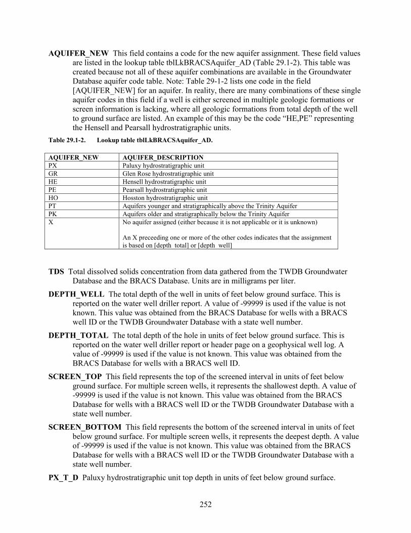
252
AQUIFER_NEW This field contains a code for the new aquifer assignment. These field values are listed in the lookup table tblLkBRACSAquifer_AD (Table 29.1-2). This table was created because not all of these aquifer combinations are available in the Groundwater Database aquifer code table. Note: Table 29-1-2 lists one code in the field [AQUIFER_NEW] for an aquifer. In reality, there are many combinations of these single aquifer codes in this field if a well is either screened in multiple geologic formations or screen information is lacking, where all geologic formations from total depth of the well to ground surface are listed. An example of this may be the code “HE,PE” representing the Hensell and Pearsall hydrostratigraphic units.
Table 29.1-2. Lookup table tblLkBRACSAquifer_AD. AQUIFER_NEW AQUIFER_DESCRIPTION PX Paluxy hydrostratigraphic unit GR Glen Rose hydrostratigraphic unit HE Hensell hydrostratigraphic unit PE Pearsall hydrostratigraphic unit HO Hosston hydrostratigraphic unit PT Aquifers younger and stratigraphically above the Trinity Aquifer PK Aquifers older and stratigraphically below the Trinity Aquifer X No aquifer assigned (either because it is not applicable or it is unknown)
An X preceeding one or more of the other codes indicates that the assignment is based on [depth_total] or [depth_well]
TDS Total dissolved solids concentration from data gathered from the TWDB Groundwater
Database and the BRACS Database. Units are in milligrams per liter. DEPTH_WELL The total depth of the well in units of feet below ground surface. This is
reported on the water well driller report. A value of -99999 is used if the value is not known. This value was obtained from the BRACS Database for wells with a BRACS well ID or the TWDB Groundwater Database with a state well number.
DEPTH_TOTAL The total depth of the hole in units of feet below ground surface. This is reported on the water well driller report or header page on a geophysical well log. A value of -99999 is used if the value is not known. This value was obtained from the BRACS Database for wells with a BRACS well ID.
SCREEN_TOP This field represents the top of the screened interval in units of feet below ground surface. For multiple screen wells, it represents the shallowest depth. A value of -99999 is used if the value is not known. This value was obtained from the BRACS Database for wells with a BRACS well ID or the TWDB Groundwater Database with a state well number.
SCREEN_BOTTOM This field represents the bottom of the screened interval in units of feet below ground surface. For multiple screen wells, it represents the deepest depth. A value of -99999 is used if the value is not known. This value was obtained from the BRACS Database for wells with a BRACS well ID or the TWDB Groundwater Database with a state well number.
PX_T_D Paluxy hydrostratigraphic unit top depth in units of feet below ground surface.
253
PX_B_D Paluxy hydrostratigraphic unit bottom depth in units of feet below ground surface. GR_T_D Glen Rose hydrostratigraphic unit top depth in units of feet below ground surface. GR_B_D Glen Rose hydrostratigraphic unit bottom depth in units of feet below ground surface. HE_T_D Hensell hydrostratigraphic unit top depth in units of feet below ground surface. HE_B_D Hensell hydrostratigraphic unit bottom depth in units of feet below ground surface. PE_T_D Pearsall hydrostratigraphic unit top depth in units of feet below ground surface. PE_B_D Pearsall hydrostratigraphic unit bottom depth in units of feet below ground surface. HO_T_D Hosston hydrostratigraphic unit top depth in units of feet below ground surface. HO_B_D Hosston hydrostratigraphic unit bottom depth in units of feet below ground surface. BK_T_D Base of Cretaceous top depth in units of feet below ground surface. PX_T_E Paluxy hydrostratigraphic unit top elevation in units of feet above mean sea level. PX_B_E Paluxy hydrostratigraphic unit bottom elevation in units of feet above mean sea level. GR_T_E Glen Rose hydrostratigraphic unit top elevation in units of feet above mean sea level. GR_B_E Glen Rose hydrostratigraphic unit bottom elevation in units of feet above mean sea
level. HE_T_E Hensell hydrostratigraphic unit top elevation in units of feet above mean sea level. HE_B_E Hensell hydrostratigraphic unit bottom elevation in units of feet above mean sea level. PE_T_E Pearsall hydrostratigraphic unit top elevation in units of feet above mean sea level. PE_B_E Pearsall hydrostratigraphic unit bottom elevation in units of feet above mean sea level. HO_T_E Hosston hydrostratigraphic unit top elevation in units of feet above mean sea level. HO_B_E Hosston hydrostratigraphic unit bottom elevation in units of feet above mean sea
level. BK_T_E Base of Cretaceous top elevation in units of feet above mean sea level. LATDD Latitude of the well site in units of decimal degrees. Latitude is a positive value,
referring to a site north of the earth’s equator. Latitude and longitude coordinates are obtained from multiple sources. Latitude is obtained is based on a North American Datum of 1983. This value was obtained from the well location table.
LONGDD Longitude of the well site in units of decimal degrees. Longitude is a negative value, referring to a site west of the Prime Meridian in Greenwich, United Kingdom. Latitude and longitude coordinates are obtained from multiple sources. Longitude is based on a North American Datum of 1983. This value was obtained from the well location table.
ELEVATION The elevation of the well site in units of feet above mean sea level. The elevation is determined using spatial analysis in a geographic information system by comparing the well site with the 30-meter digital elevation model for Texas. This value was obtained from the well location table. A value of -99999 is used if the value is not known.
OWNER The name of the well owner. This value was obtained from the well location table.
254
INS_ID Unique ID assigned to each record to ensure the data from well records processed in GIS are precisely assigned to the corresponding database record. This field performs as the key field for the table.