Embed Size (px)
Citation preview

1
BrainWave™Electronic Mixing Valve
Programmer Software Guide
BrainWave™ is a registered trademark of Armstrong Hot Water, Inc. a division of Armstrong International, Inc.
BrainWave™ features Rada technology, Rada® is registered to Kohler-Mira, Inc. of Cheltenham, England.
AHWG-701

2
CONTENTS
DESCRIPTION ............................................................................................................................................. 3System Requirements ............................................................................................................................. 3
INSTALLATION ........................................................................................................................................... 3PASSWORD ADMINISTRATION ................................................................................................................ 4
Setting up Users and Passwords for a New Installation .......................................................................... 4ENTRY LEVEL............................................................................................................................................. 5
Login ....................................................................................................................................................... 5Read Valve Data ..................................................................................................................................... 5Main Menu (Single / Outlet) ..................................................................................................................... 6Main Menu (Bath / Shower) ..................................................................................................................... 7Setting Outlet Temperatures ................................................................................................................... 8Setting Flow Times .................................................................................................................................. 8Storing Setup to the Valve ....................................................................................................................... 9Checking Setup is Stored ........................................................................................................................ 9Thermal Disinfection (Arming) ............................................................................................................... 10Thermal Disinfection (Triggering) .......................................................................................................... 11Thermal Disinfection (Checking for Completion) ................................................................................... 12Thermal Disinfection (Saving Log) ........................................................................................................ 12Thermal Disinfection (Failed Disinfection) ............................................................................................. 13
ENGINEERING LEVEL .............................................................................................................................. 14Login and Read Valve Data .................................................................................................................. 14Main Menu ............................................................................................................................................ 15Setting Service Flush: Step 1, Valve Setup ........................................................................................... 16Setting Service Flush: Step 2, Outlet Setup .......................................................................................... 16Setting Disinfection: Step 1, Valve Setup .............................................................................................. 17Setting Disinfection: Step 2, Outlet Setup ............................................................................................. 17Engineering Menu ................................................................................................................................. 18Valve Information (Engineering Level Only) .......................................................................................... 19Commissioning Data (Engineering Level Only) ..................................................................................... 19Service Data (Engineering Level Only) ................................................................................................. 20Disinfection Configuration (Engineering Level Only) ............................................................................. 20Valve Usage Data (Engineering Level Only) ......................................................................................... 21
FAULT FINDING ........................................................................................................................................ 22Self Diagnosed Errors Table ................................................................................................................. 22
VALVE CALIBRATION .............................................................................................................................. 23ERROR MESSAGES ................................................................................................................................. 23CUSTOMER CARE .................................................................................................................................... 24

3
DESCRIPTIONThe CD contains software that is designed to run on a Pocket PC PDA.
The software communicates with the mixing valve and allows the user to:
Access Levels
Password Administration: Add new users and change passwords.
Entry Level: Set outlet temperatures, flow times and do thermal disinfection.
Engineering Level: Enable service flush and disinfection, view valve information, set commissioning andservice data.
System Requirements
The installation CD is designed to run on Microsoft Windows 98/NT/2000/XP operating systems. The programmer softwareis designed to run on Microsoft Pocket PC 2002 and Microsoft Mobile Windows for Pocket PC 2003.
INSTALLATIONPlease make sure that you have installed Microsoft ActiveSync on to your PC (supplied with your PDA). With your PDAconnected to your computer follow the instructions below.
Insert the CD-ROM. The CD should start automatically. If the CD does not start automatically then please use thesupport instructions on the CD wallet.
Select the install programmer software button from the menu and follow the installation menus. If you are prompted toinstall “Microsoft.Net Compact Framework”, choose “Yes”.
The software will automatically download to your PDA. To check if the installation was successful, go to the start menuon the PDA and look for the control panel icon called “Rada Sense”.
If you cannot find the link in the start menu go into Programs and double click on the Rada Sense icon.
You are now ready to set up passwords and add new users, please go to the next section.
If you wish to install the software on more than one PDA, when you have completed the first installation attach each PDAto your PC and open Microsoft ActiveSync. Select Tools, Add/Remove Programmes, select Kohler Mira Ltd Rada Senseby ticking the box, then click OK.

4
Tap on “Password”.
Default passwords shown.
Enter new Passwords in boxes,then tap “OK”.Enter
IDName
Password
Password Admin.
OK Cancel
3
4
Adding a PasswordNote! Password contains up to 5 alphanumeric characters.
Adding a New UserNote! Each user must have a unique ID.
Enter Name(maximum of 15 characters)
and ID (a 4 digit number).
List of valid users and IDs.
Tap “Enter”.
IDName
EnterPassword
Password Admin.
PASSWORD ADMINISTRATIONSetting up Users and Passwords for a New InstallationA new software installation will have no User IDs and default Passwords.To gain access to the programmer functions at least one User ID must be entered. It is recommended to change thePasswords from the default values.
Leave the ID box blank and enter 99999 in the Password box.
Click on “Enter”.Enter
PasswordID
1
Click here to make the keyboard appear.
1
2

5
Login
Login Screen
Disable the Control Panel with the magnetic key(Control panel is disabled when it is not illuminated).
ENTRY LEVELLogin and Read Valve Data
Disable User Interface
Tap on “Enter”.Enter
Password33331 Enter ID but leavePassword box blank.
2
Click here to make the keyboard appear.
ID
Read Valve Data Reading Valve
Aim the Programmer at the Control Panel.
Read Valve Data
2
Ensure Control Panel is disabled.
Aim PDA at Control Panel andtap ‘Read Valve Data’ button.
Ensure Control Panel is disabled.
Aim PDA at Control Panel andtap ‘Read Valve Data’ button.
Note! If an error occurs,refer to “Error Messages”.
Read Valve Data is successfulwhen the main menu is displayed.
1 Tap here to readcurrent valve data.

6
Tap on one of these options.
Main Menu (Single / Outlet)
Outlet Setup
Flow Times
Disinfection
Rada SenseMain Menu
Valve Disinfection
Arm Trigger
Read Log Clear Log
Outlet
Flow Times
Mins Secs
Read Write
OutletTemperatures (°F)
Max Min
Full Cold
Disinfection
Service Flush
Read Write
Options
Default

7
Shower Setup
Bath Setup
Flow Times
Disinfection
Valve Disinfection
Arm Trigger
Abort
Read Log Clear Log
Rada SenseMain Menu
Main Menu (Bath / Shower)
OutletTemperatures (°F)
Max Default Min
Options
Full Cold
Disinfection
Service Flush
Read Write
Options
Full Cold
Disinfection
Service Flush
OutletTemperatures (°F)
Max Default Min
Read Write
Shower
Bath
Flow Times
Mins Secs
Read Write

8
OutletTemperatures (°F)
Max Min
Full Cold
Disinfection
Service Flush
Read Write
Options
Default
Setting Outlet Temperatures
Enter the temperature range available to user (30°-50°)Note! Default = Switch on temperature
If checked the user can select full cold.
Setting Flow Times
Shower
Bath
Flow Times
Mins Secs
Read Write
Note! Changes will not be stored in valve until “Write” is tapped (refer to “Storing Setup to the Valve”).
Enter the flow time before automatic switch off(5 secs - 59 minutes, 59 seconds).
Note! Changes will not be stored in valve until “Write” is tapped (refer to “Storing Setup to the Valve”).
Refer to “Engineering Menu”.
CancelYes No
Do you want to Write thechanges to the valve Warning menu if “Write” is not tapped
Warning

9
Storing Setup to the Valve
Writing the changesto the valve.
OutletTemperatures (°F)
Max Default Min
Full Cold
Disinfection
Service Flush
Read Write
Options
Writing
ShowerTemperatures (°F)
Max Default Min
Read Write
Options
OK
Full Cold
Disinfection
Service Flush
Tap “Write”.
Aim the Programmer at the ControlPanel and tap “Write”.
“OK” means the setup changes have been stored.
If “OK” is NOT displayed or an error is displayed then the changeshave not been stored.
Caution! The outlet temperature must be re-checked after a newtemperature has been programmed, refer to ‘Checking Setup isStored’.Checking Setup is Stored
“OK” means the setuphas been read fromvalve.
Check setup is correct.
Max Default Min
Read Write
OK
Options
Read Write
OutletTemperatures (°F)
Full Cold
Disinfection
Service Flush
OutletTemperatures (°F)
Full Cold
Disinfection
Service Flush
Options
Aim the Programmer at the Control Paneland tap “Read”.
Max Default Min
Tap “Read”.
10
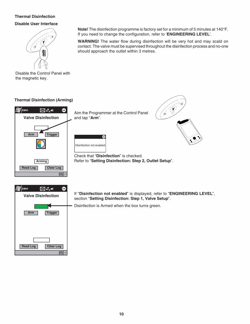
Thermal Disinfection (Arming)
If “Disinfection not enabled” is displayed, refer to “ENGINEERING LEVEL”,section “Setting Disinfection: Step 1, Valve Setup”.
Disinfection is Armed when the box turns green.
Valve Disinfection
Arm Trigger
Read Log Clear Log
Arming
Valve Disinfection
Thermal Disinfection
Disable User Interface
Arm Trigger
Read Log Clear Log
Note! The disinfection programme is factory set for a minimum of 5 minutes at 140°F.If you need to change the configuration, refer to ‘ENGINEERING LEVEL’.
WARNING! The water flow during disinfection will be very hot and may scald oncontact. The valve must be supervised throughout the disinfection process and no-oneshould approach the outlet within 3 metres.
Disable the Control Panel withthe magnetic key.
Aim the Programmer at the Control Paneland tap “Arm”.
Disinfection not enabled
Check that “Disinfection” is checked.Refer to “Setting Disinfection: Step 2, Outlet Setup”.

11
Aim the Programmer at the Control Panel and tap “Trigger”.
This must be done within 30 seconds of Arming or the valve must be Armed again.
Thermal Disinfection (Triggering)
Triggering the disinfection.
Disinfection is triggered when box turns red.
Waterflow starts when countdown reaches 0.
Note! The Control Panel is enabled during disinfection, if any sensor is activated thenthe disinfection cycle is aborted.
WARNING! For continued protection against legionella, thermal disinfection must becarried out on a regular basis. Please consult your national guidelines for details.
Valve Disinfection
Arm Trigger
Read Log Clear Log
Triggering
Valve Disinfection
Arm Trigger
Read Log Clear Log
OK
3
Move away fromoutlet danger of
scalding

12
Thermal Disinfection (Saving Log)
Tap “File” to save log to file.Log file format (Use Pocket Word to view).
Disinfection Log
Time (mins)
Disinfection completed
Thermal Disinfection (Checking for Completion)
Reading the disinfection log.
“Disinfection Completed” indicates temperature held forcorrect time.
Valve Disinfection
Arm Trigger
Read Log Clear Log
Disinfection Log
Time (mins)
No disinfection data
Reading Log
When flow stops tap ‘ReadLog’ to check for completion
Aim the Programmer at the Control Panel and tap “Read Log”.
Tap “Read Log”.

13
Thermal Disinfection (Failed Disinfection)
“Disinfection failed!” Indicates temperature not held for long enough.
Check water supply and disinfect once it has been corrected.
Disinfection Log
Disinfection failed!
Time (mins)

14
Tap here to readcurrent valve data.
Read Valve Data Reading Valve
Note! If an error occurs,refer to “Error Messages”
Read Valve Data is successfulwhen the main menu isdisplayed.
12
Ensure Control Panel is disabled.
Aim PDA at Control Panel andtap ‘Read Valve Data’ button.
Ensure Control Panel is disabled.
Aim PDA at Control Panel andtap ‘Read Valve Data’ button.
ENGINEERING LEVELLogin and Read Valve DataDisable User Interface
Tap on “Enter”.Enter
PasswordID
Aim the Programmer at the Control Panel.
Read Valve Data
*****5555
1 Enter User ID and Engineer Password.
2

15
Main Menu
Additional Engineering options
Tap on one of these Options.
Rada SenseEngineering
Valve Information
Commissioning Data
Service Data
Valve Calibration
ValveService Flush
Temp. (F) Duration (mins)
Read Write
Disinfection
Service Flush
Flow Times
Disinfection
Main Menu
Outlet Setup
Valve Setup
Engineering
Options
Refer to “Engineering Menu”.
Days HoursWait Time
Disinfection Config.
Usage Data
Refer to “Setting Service Flush:Step 1, Valve Setup”.

16
ValveService Flush
Temp. (F) Duration (mins)
Read Write
Disinfection
Service Flush
Options
Days HoursWait Time
ShowerTemperatures (°F)
Max. Default Min.
Full Cold
Disinfection
Service Flush
Read Write
Options
OK
Setting Service Flush: Step 1, Valve Setup
Check this box to enableService flush.
Note! Changes will not be stored in valve until “Write” is tapped (refer to “Storing Setup to Valve”).
Enter temperature, durationand wait time.
Setting Service Flush: Step 2, Outlet Setup
Note! Changes will not be stored in valve until “Write” is tapped (refer to “Storing Setup to Valve”).
‘Service Flush’ in ValveSetup must be checked toenable this function
Check that “Service Flush” is checked.Check this box to enableService flush.

17
ValveService Flush
Temp. (F) Duration (mins)
Read Write
Disinfection
Service Flush
Options
Days HoursWait Time
Setting Disinfection: Step 1, Valve Setup
Check this box to enabledisinfection.
Note! Changes will not be stored in valve until “Write” is tapped (refer to “Storing Setup to Valve”).
Check this box to select thisoutlet for disinfection.
Note! Changes will not be stored in valve until “Write” is tapped (refer to “Storing Setup to Valve”).
Setting Disinfection: Step 2, Outlet Setup
OutletTemperatures (°F)
Max. Default Min.
Full Cold
Disinfection
Service Flush
Read Write
Options‘Disinfection’ in ValveSetup must be checked toenable this function
Check that “Disinfection” is checked.

18
Rada SenseEngineering
Valve Information
Commissioning Data
Service Data
Valve Calibration
Disinfection Config.
Valve Usage Data
Engineering Menu
Valve Information
Serial No.
Manufacture Date andTime
Firmware Type
Firmware Version
Calibration No.
Commissioning Data
Location
Commissioned on 7/4/2005 at 6:53 PM
EMV 1
Set Commission Data
Tap on one of these Options.
Service Data
Valve is OK
Last serviced by 1234
on 7/21/2005 at 3:07 PM
Set Service Date
Valve Calibration Disinfection Configuration
Min. Temp. (°F)
Type
Energy SavingReduced
Read Write
Valve Usage Data
Activations
Count Total Minutes
Hourssince Disinfection
since last used
Stepper MotorPulses
Read Write
DaysFlow
Min. Time (mins)
Max. Warmup (mins)
Max. Duration (mins)
Upper Temp. (°F)
Interface Version
19
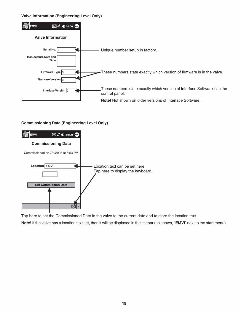
Valve Information (Engineering Level Only)
Valve Information
Serial No. Unique number setup in factory.
These numbers state exactly which version of firmware is in the valve.
Manufacture Date andTime
Firmware Type
Firmware Version
Interface Version These numbers state exactly which version of Interface Software is in thecontrol panel.
Note! Not shown on older versions of Interface Software.
Commissioning Data (Engineering Level Only)
Location text can be set here.Tap here to display the keyboard.
Tap here to set the Commissioned Date in the valve to the current date and to store the location text.
Note! If the valve has a location text set, then it will be displayed in the titlebar (as shown, “EMVI” next to the start menu).
Commissioning Data
Location EMV I
Set Commission Data
Commissioned on 7/4/2005 at 6:53 PM

20
Disinfection Configuration (Engineering Level Only)
Enter minimum temperature required to disinfect.
If checked, the flow rate will be reduced during disinfections to save water.
Enter minimum disinfection duration.
If disinfection temperature is not reached within this period, then disinfectionwill be cancelled (if unsure, leave as default).
If disinfection is not completed within this period, then disinfection will becancelled (if unsure, leave as default).
Disinfection ConfigurationMin. Temp. (°F)
TypeStandard
Read Write
Min. Time (mins)
Max. Warmup (mins)
Max. Duration (mins)
Flow
Disinfection ConfigurationMin. Temp. (°F)
TypeEnergy Saving
Read Write
Min. Time (mins)
Max. Warmup (mins)
Max. Duration (mins)
Flow
Upper Temp. (°F)
Reduced
Reduced If “Type (Energy Saving)” is selected, then the valve will reduce the requiredperiod for disinfection proportionally as the temperature increases up to thelimit specified in “Upper Temp. (°F)”.
Warning! Time reduction is not permitted by some National/LocalRegulations. If in doubt, select “Standard” settings.
Service Data (Engineering Level Only)
Service DataValve is OK
Last Serviced By 1234
on 7/21/2005 at 3:07 PM
“Valve is OK” means that no errors have been detected by the valve.
User ID and Date of last service.
Tap here to set the Serviced Date in the valve to the current date.Set Service Date

21
Valve Usage Data (Engineering Level Only)
Valve Usage DataActivations
Count Total Minutes
Hours
Since Disinfection
Since last used
Stepper Motor Pulses
Days
These are counted from when the valve is first switched ‘ON’.
Either time since the valve was last used or since the last Service flush.
This indicates how much work the motor has done. This information is requiredby the service engineer or agent for diagnostic use.

22
Error Text Cause / RectificationCode
Self Diagnosed Errors Table
3
7
Over temperature - T1
Over temperature - T2
4 Temperature sensorfault
60
70
Stepper motor stuck
Stepper motor positionerror
Anyother
Pcb fault
Thermistor faulta. Contact Armstrong Hot Water, Inc.
The stepper motor is stuck, the motor belt is broken or the assembly is jammed.a. Contact Armstrong Hot Water, Inc.
The mixer assembly is jammed or very stiff.a. Contact Armstrong Hot Water, Inc.
Outlet temperature is too high or thermistor faulta. The inlet/outlet fittings may be blocked: check the inlet/outlet strainers.b. Cold water supply failure: reinstate supply.c. Safety circuit may require resetting: enable the control panel with magnetic key to
reset.d. If the symptom has not been rectified, contact Armstrong Hot Water, Inc.
A fault has occurred on the Control PCB.a. Memory may require resetting: switch the power supply to the electronic mixing
valve, OFF then ON.b. If the symptom has not been rectified, contact Armstrong Hot Water, Inc.
FAULT FINDINGSelf Diagnosed Errors
If the valve has detected an error, the “Service Data“ screen will be automatically displayed as soon as “Read ValveData” has completed.
Service DataValve Error!
Last Serviced By 1234on 7/21/2005 at 3:07 PM
The valve has an error.
Pcb fault
Code Unique code number of error shown here(refer to “Self Diagnosed Errors Table”).
Text shows faulty component.Set Service Date
36

23
VALVE CALIBRATIONCaution! The valve must be calibrated, if the mixing valve assembly or the control pcb are replaced. The calibrationnumber is required and this will be found on the mixing valve body.
Enter calibration number.
Aim the Programmer at the Control Panel and tap “Write”.
Valve Calibration
Calibration No.
Read Write
CancelOK
Read Write
Valve Calibration
This will affect the valveperformance.
Please ensure 180 matchesthe value printed on the valvebody.The calibration number will not
be stored until “OK” is tapped.
ERROR MESSAGES
Control Panel not disabled or Programmer not aimed at Programming window.
Lost connection duringcommunication.
Failed to connectPlease try again
Or Control panelnot Ready
Lost ConnectionYes No
Do you want to Write thechanges to the valve
Warning
Disinfection not enabled
Check that “Disinfection” ischecked. Refer to “SettingDisinfection: Step 2,Outlet Setup”.
‘Service Flush’ in Valve Setupmust be checked toenable this function
Check that “Service Flush”is checked. Refer to“Setting Service Flush:Step 1, Valve Setup”.
‘Disinfection’ in ValveSetup must be checked toenable this function
Check that “Disinfection” ischecked. Refer to “SettingDisinfection: Step 1, ValveSetup”.
Check that “Write” istapped.Refer to “Setting OutletTemperatures”.Cancel
Warning
Warning

24
Armstrong Hot Water, Inc.
Limited Warranty and Remedy
Armstrong Hot Water, Inc. (“Armstrong”) warrants to the original user of those products supplied by it and used in theservice and in the manner for which they are intended, that such products shall be free from defects in material andworkmanship for a period of one (1) year from the date of installation, but not longer than 15 months from the date ofshipment from the factory. This warranty does not extend to any product that has been subject to misuse, neglect oralteration after shipment from the Armstrong factory. Except as may be expressly provided in a written agreementbetween Armstrong and the user, which is signed by both parties, Armstrong DOES NOT MAKE ANY OTHERREPRESENTATIONS OR WARRANTIES, EXPRESS OR IMPLIED, INCLUDING, BUT NOT LIMITED TO, ANY IMPLIEDWARRANTY OF MERCHANTABILITY OR ANY IMPLIED WARRANTY OF FITNESS FOR A PARTICULAR PURPOSE.
The sole and exclusive remedy with respect to the above limited warranty or with respect to any other claim relating tothe products or to defects or any condition or use of the products supplied by Armstrong, however caused, and whethersuch claim is based upon warranty, contract, negligence, strict liability, or any other basis or theory, is limited to Armstrong’srepair or replacement of the part or product, excluding any labor or any other cost to remove or install said part orproduct, or at Armstrong’s option, to repayment of the purchase price. As a condition of enforcing any rights or remediesrelating to Armstrong products, notice of any warranty or other claim relating to the products must be given in writing toArmstrong: (i) within 30 days of last day of the applicable warranty period, or (ii) within 30 days of the date of themanifestation of the condition or occurrence giving rise to the claim, whichever is earlier. IN NO EVENT SHALLARMSTRONG BE LIABLE FOR SPECIAL, DIRECT, INDIRECT, INCIDENTAL OR CONSEQUENTIAL DAMAGES,INCLUDING, BUT NOT LIMITED TO, LOSS OF USE OR PROFITS OR INTERRUPTION OF BUSINESS. The LimitedWarranty and Remedy terms herein apply notwithstanding any contrary terms in any purchase order or form submittedor issued by any user, purchaser, or third party and all such contrary terms shall be deemed rejected by Armstrong.
BrainWave™ EMV is covered by a 5-year warranty against defects in materials or workmanship from the date of purchase/shipment . Armstrong reserves the rights to replace either the complete product, certain components of the product and/or replacement internal operating parts.
Customer Care
Armstrong Hot Water Group, 816 Maple Street, Three Rivers, Michigan 49093 • USA Ph: (269) 279-3602 Fax: (269) 279-3130
Printed in U.S.A.www.armstrong-intl.comAHWG-701 - P5409 9/05