Embed Size (px)
Citation preview
•
•
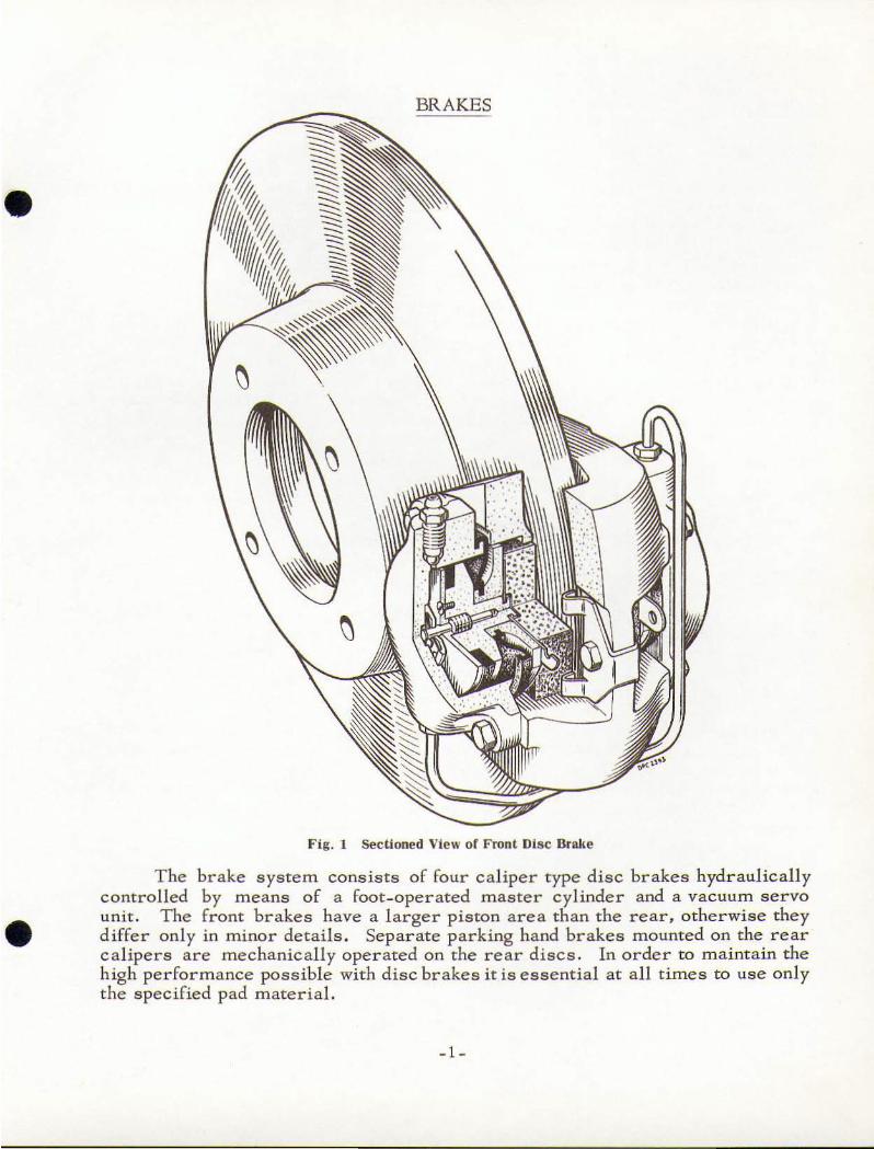
BRAKES
Fig, 1 Sectioned View of Front Disc Brake
T he brake syste m cons is t s o f four caliper type disc brakes hydraulic ally
cont rol1ed by m eans of a foot- operated master cylinder and a vac uum servo unit . The front brakes have a l arger pis ton a rea tha n the rear, otherwise they
d iffer on ly in m inor details. Separ ate parking hand brakes mounted on the r ear calipers are mechanically ope r ated on the rear discs. In order to m a inta in the
h igh performance possible with d i sc brakes it is essential at a ll times to use only
the specified pad material.
-1 -
DESCR1PT10N
Disc Brakes
Each whee l brake unit comprises a hub mounted disc rotating with the
wheel. and a braki ng UnIt rigidly attached to the suspension m ember . T he brake umt conS.lsts of a ca1.iper whic h straddles the cl isc a nd houses a pair of rect
angular fricclOn pad assembhes, each comprtsing a pad and a securing plate.
These assemblies locate between a keep plate bolted to the cal iper bridge and twO
support plates accommodated in s lots in the cal.iper jaw . Cylmder blocks bolted to the outer faces of the caliper accommodate plsron assembl ies which are
keyed to the frict ion pad assemblies . A spigot for'med on the outer face of each
p,iston locates in the bore of a backing plate with an integral boss grooved to
8Gcommodate the co ll ar of a flexible rubber dust seal. The outer rim of the
seal engages a groove around the block face and so protects the assembl y fr0 111 intrusion of moisture and for'eign matter. A piseon seal is located be tween the
piston inner face and a p l ate secured by peened locked screws. A counterbore
in the piston accommodates a retractor bush whIch tightly grips the stem of a
retractor pin . This pin forms part of an assembl y which IS peened into the base o f the cylinder bore. T he assembly compr ises a retracrer stop bush, two sprIng
washers, a dished cap and the retractor pin; it functions as a return spring and maintains a Hbrake_off" working clearance o f approxi mately 0.008/ 0 .010 in.
between the pads and t hp- disc throughout the life of t he pads.
Hand Brake
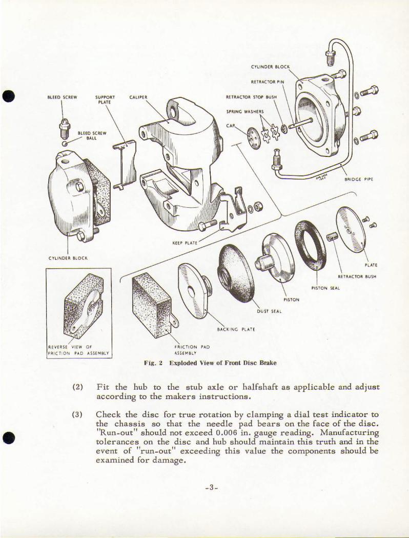
The mec ha nicall y ac tuated hand br akes a re attached to the caliper bodies
of the rear brakes by means of hinge bolts. Each brake consists of two carriers which locate ascnde the b['akf" dJ sc, and riveted to the inner face of each car rier
is a friction pad . The inner carrier is equipped with a pivot. seat tu which is pinned the fork end or an oper'ating lever. A trunnlo r1 mounted within the levt:: t'
for k carries a l'Iu"caded bolt, the end of which is fittE"d wit.h a .lockout. This bo lt
passes thro ugh the carriers and ter minates wit_h a he misphencally formed head which seats in a similarly shaped recess in the outer carr ier. Located around
the bolt and registering in a counterbore 1 11 rhe inner carrier is an operating
lever return spring retained under load by a nut. A spring p late s ecured to the
inner face of the carrier by screws and Shakeproof washers locks the nut In
position.
INSTALL ATION
Disc Brake s
T he assembly of the disc brake t o the car shou ld be carried out as
follows : -
(t) Sec ure t he disc to the hub with the bolts, spring washers and nuts provided.
- 2 -
•
•
•
CYlINOfk
aUto ~CUW CAUPI R k[lt\"'C10~ S10f' aUSH
l ""0 ""'. ~ ''''
C YL INOUl a lOC k,
""e",o, ",0
HHMBLl
S"'CKINC PI. ... H
Sf SUI.
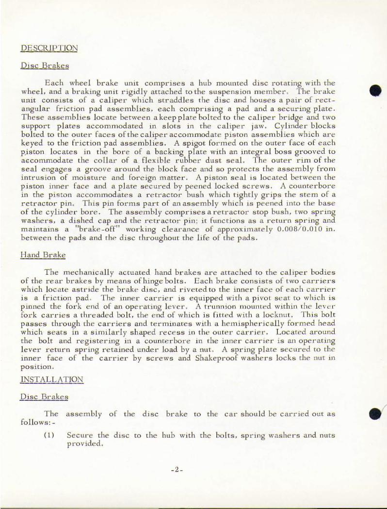
Fig. 2 Exploded View of Front Disc Brake
~ L "H
RnR"ClO~ BUSH
(2) Fit the hub to the stub axle or halfshaft as applicable and adjust
according to the makers instructions.
(3) Check the disc for true rotation by cl a mping a dial test indicator to the chassis so that the needle pad bears on the face of the disc.
"Run-out" s hould not exceed 0.006 in. gauge reading. Manufacturing
tole r ances on the disc a nd hub should maintain this truth and in the event of "run- out 11 exceeding this value the components shoul d be
examined for damage.
- 3 -
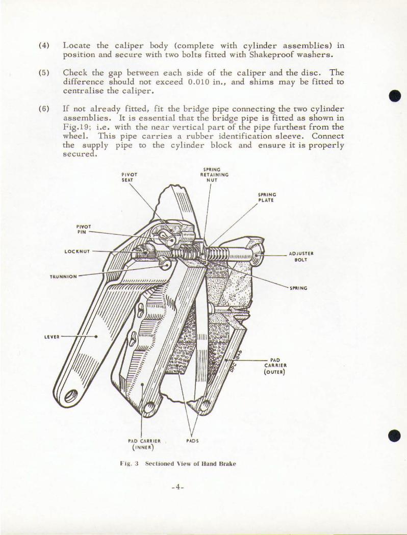
(4) Locate the calipe r body (com ple te with cylinder ass e mblies ) In
positio n and secure with two bolts fitted with Shakeproof was her s.
(5)
( 6 )
C heck the gap between each side of the calipe r and the dis c. T he d iffe r e nce s hould not exceed 0.010 in., and s him s m ay be fitted to centra lise the caliper.
If not already fitted, fit the bridge pipe connect i ng the two c ylinde r assemb lies . It is essential that the br idge pipe is fitted as shown in F ig .1 9; i.e . with the near vertical part of the pipe fu r the st from the wheel. This pipe carries a rubber identification s leeve. Connect the s upply pipe to the cylinder block and ensure it is properly secured .
PIVOT
""------' l OCItNUT - ---,.t-
TRU NNION
~ ___ " OJUSTEIt
eOlT
LEVER - --If/-~
' :.0 CUltL U
( LNN EIt)
l: iS . 3 Sectione d \ ie w or lIand Hmkp
_4_
- - - ''0 C"'ULEII:
(OUTfit)
•
•
•
•
Hand Brake
Slacken the carrier adjuster bolt, position the carrier in the rear caliper
and secure t hem with the bol ts and lockwashers. Set the brake clearance by
tightening the adjuster bolt unti l the pads are lightly in contact with the disc and then s lacken the bolt 1/3 turn. This c learance should he reset when the travel
of the hand brake lever becomes excessive.
Handbrake Lever
H and brake traveL fully -on to fu ll y-off, 4 to 5 teeth on racket. To adj ust traveL set handbrake l ever fully_off. With road whee l free to rotate by hand,
insert screwdriver through any hole in wheel opposite to handbrake-pad adjusting screw and tighten screw sufficientl y to prevent wheel from turning then slacken back one-third of a turn, allowing wheel to be rotated by hand.
Foot-Brake Pedal and Master Cyl inder
Master cylinder is Lockheed manufacture but is modified and it is important
to note that replacements m us t be obtained fro m the car manufacturers.
A brake-fluid level switch is fitted to the maste r cylinder flu id r eservoir
and is wired to a flu id -level-warning light fitted to the dashboard.
Brake-pedal positioning is important . To achieve an approximate distance of 6! in. from the carpet on the scuttle to the centre line of t he pedal pad, the distance from t he sphe rical end of the push-rod to the ho le in the fork - e nd should be maintained at 6 i n. The return stop s hould then be set to give 1/32 in. free
trave l.
Priming and Bleeding the Brake System
The following procedure should be adopted either for initial priming of the
system, or to b leed in service if air has been permitted to enter the system. This l atte r condition may occur if connections are not m aintained properly tightened,
or if the master cylinde r periodic fluid level c heck is neglected. During the b leeding operation it is important that the level in t he reservoir is kep t tOpped up to avoid drawing air into the system. it is recommended t hat new fluid be used
for this purpose but when this is not possible the original fluid m a y be returned
to the reservoir, providing it is clean and free from air.
(1) Check that all connections are tightened and all bleed screws closed .
( 2 ) Fi ll the reservoir with brake flu id of the corr ect specification.
(3) Attach the bleeder tube to the b leed screw on the near s jde rear brake and immerse the open end of the tube in a s m a ll quantity of brake
-5 -
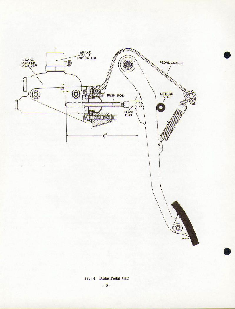
F ig . 4 Brake Pedal Unit
-6-
•
o
•
•
•
(4)
fluid contained in a cJean g lass jar. Slacken the bleed screw and
operate the brake pedal slowl y backwards and forwards t hrough its fu ll stroke until fluid pumped into the jar is reasonably free from air
bubbles . Keep the pedal depressed and close the bleed screw. Re lease the pedal.
Repeat for each brake in t urn .
(5) Repeat the complete bleeding seque nce unt il the brake fluid pum ped
in to the jar is completel y free from air bubbles.
(6) Lock a ll bleed screws and finally regulate the flu id level in the reservoir .
(7) Apply normal working load on the brake pedal for a period of two or three minutes and examine the entire system for leaks.
Servicing
General
The complete brake system is designed to r equire t he minimum of
attention and providing the hydraulic fluid in the reservoi r is not allowed to fall below the recommended level no defectsshouldnorrna lly occur. F luid loss must
be supplemented by periodically topping up the reservoir with fluid of the same specifications of that in the system. When alternative approved fluids are specified. the complete sys tem must be drained before the substitution of one fluid for another. It is notpermissable to top up the reservoir with an alternative
approved brand of fluid.
The inclusion of air in a system of t his type will be indicated by s l uggish
response of the brakes and spongy action the brake pedal. This cond ition m ay be due to air induction at a loose joint or at a reservoir in which the fluid has been
a llowed to fall to a very low leve l. These defects must be immediately remedied and the complete system bled. Similarly. bleeding the system is equally essential
fo llowing any servicing operation involv ing the d isconnecting of part or whole of
the hydraulic system.
The following instructions dp.ta il t he procedure for renewal of component parts and for complete o ve rhaul of the disc br akes, hand brakes and master cylinder . T he units shou ld be thoroughl y cleaned externally be fore d ismantling. B r ake system fluid should be used for cleaning internal components, and. except where otherwise stated in t hese notes, the use of petrol. paraffin or chemical
grease solvents should be avoided as they may be detrimental to the rubber components . T hroughout the d ismantling and assemb ling operation it is esselttia l that the work bench be maintained in a clean condition and that the components are
not handled with dirty or greasy hands. The precision parts should be handled with
extre me care and s hould be carefully placed away from tools or other equipment
l ikel y to cause damage. After cleaning a ll compone nts should be dr ied with clean l int-free rag.
_7_
When it is not the intention to renew t he r ubber component s they must be
carefully e xamined for serviceabi l i ty . T here must be no evidence o[ de fects
s uch as per ishing excessive swe ll ing, cutt ing O t- twist ing and whe r e doubt e xi s ts
c ompariso n with new parts may p r o ve to be of s o me assistance in m aking an
assess ment of t heir condition . The, flex ible p ipes mu st show no s igns of de terior
ation o r dam age and the bo res should be cleaned wi th a je t o f compressed air .
No attempt s hould be m ade to clear blockage by pr ob ing as thi s may result in
damage to the l ining a nd seriou s res triction to flui d flo w . Par t ially o r totally
blocked flex ible p ipes must a lways be renewed . Whe n removing or re - fitting a
fl exible pipe to end s leeve hexago n must be held with the app r o p r iate s p anne r to
p r event t he pip e fro m twisting . A t wisted pip e w i ll p r o ve de t rimental to efficient
brake ope r ation .
Renewin£ the Friction Pads
Brake ad ju s t ment is a u tomatic du ring the we aring life of the pads. The
p ads should be che cke d for wear at fr e quent intervals by visual o bs e rvatio n and
meas ure m e n t; whe n wear has reduced the pads to t he minimum permissible
thickness of 0 .250 in ., the p ad assemb l ies (comp lete wlth secu ring p l ate s) must
be r enewed. If checking is neglected th e need to rene w t he pad s will be ind icated
by a loss of brake efficiency. T h e friction pad s f itte d have been sele cted as a
result of intensive d e velopment. In o r der to m a intain the high perfor m a nce
p ossible it i s essential at all times to use o n ly the s p ecified p ad mate rial. To
fit new frict ion pad asse mb l ie s as fo llows: -
( 1) Remove the nut, washer and bolt securing t he ke ep pl ate and withd raw
th e plate .
(2 ) With a s u itable hooked implement engaged in the hole in the lug o f the
securing pl ate withdraw t he defective p ad assemblies.
(3 ) Tho roughly cle an, the backing plate , dust seal, and the surrounding
area or t he cal iper .
(4) With t he a id o ftht- speCial too l (refer to t he relevant Data She et) press
in the p iston asse mbl ies to t he b ase o f the cylinder bores. as
describe d in the Fo l lowing in struct ion (5).
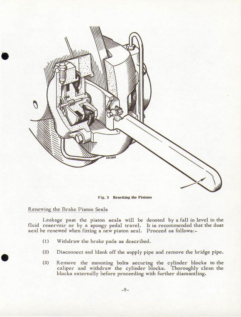
( 5 ) Insert the for ked e nd o f the p iston r e - setti ng l e ve l- (refer to F ig .S)
into the space between the cal iper bridge and o ne of the piston backing
pl ates. wi th the fork astrid e the p r oj ecting p iston s p igot and its convex
fac e bearing on the piston backing p l ate . Locate t he spigot end of
the lever p in in the keep pl ate bo lt ho le in t he bridge. Pivot the leve r
about t he pin to force the p is ton to the base of lts cylinde r. Inse r t
the new friction p ad assembly. R epeat th is ope ration for the opposite
piston asse mbl y .
(6 ) Repl ace the keep plate and secu re it with the bolt, washer and nut .
- 8 -
•
•
•
•
Fig.::; ResetUng the Pistons
Renewing the Brake_Piston Seals
Leakage past the piston seal s will be fluid reservoir or by a spongy pedal travel.
seal be renewed when fitting a new piston seal.
denoted by a fall in level in the It is recommended that the dust
Proceed as follows:-
(1) Withdraw the brake pads as described.
(2)
(3 )
Disconnect and blank off the supply pipe and remove the bridge pipe.
Remove the mounting bolts securing the cylinder blocks to the
caliper and withdraw the cylinder blocks. Thoroughly clean the
blocks externally before proceeding with further dismantl ing.
-9 -
(4) DIsengage the dust seal from the groove around the cyl inde r block face.
(5 )
(6 )
(7 )
Connect the cylinder block to a source of fluid supply and apply pressure to e ject the piston assembly.
Remo ve the screws secunng the plate to the plston, lift off the plate
and pis ton seal, withdraw the retractor bush from within the piston
bore. Carefully cut: away and discard the dust seal.
Support the backing plate on a bush of sufficient bore diameter to
just accommodate t he plston , With a suitable tubular distance p1ece
placed against the end of the piston spigot and located around t he
shouldered head, press out the piston from the backing plate. Care
must be taken during t h is operation to avo id damaging the piston.
(8) Engage the collar of a ne w dust seal with the lip on the backing plate,
avoiding harmful stretching.
(9) Locate the backing plate on the piston spigot and with the piston
suitab ly supported press the backing plate fully home.
(10) Jnsert the retractor bush into the bore of the piston. Lightly lubricate
a new piston seal with brake flUId, and fit it to t he piston face, Attach
and secure l:he plate with the SCrews, and peen lock the screws.
(11) Check that the piston and the cylinder bore are thoroughly clean and
show no signs of damage . Locate t he piston assembly on the e nd of
the retractor pin . With the aid of a hand press slowly appl y an even
pressure to the backll1g plate and press the asse mbly into the cyJinder
bore. During this operation ensure the piston assembly is in COrrect
alIgnment in relation to the cylinder bore, and that the piston seal
does not beco m e tWIsted or trapped as it: enters. Engage the outer
nm of the dust seal in the groove around the cy linder block face .
Ensure that the two support plates are in position .
(l2) Re - assemble t he cyl inder blocks tothecaliper. Fitthe bridge p ipes,
ensuring that they are correctly positioned. Remov e the blank and
reconnect the supply pipe.
(l3) Fit the pad assemblies and the keep pl ate. Prim e and bl eed the system as desc ribed.
Re - lining the Hand Brake
The recommended procedure for' renewing t he fr iction pads is as follows : -
-10-
•
•
•
•
HAND 8RAK.E LEVER
~ I' /OT PIN I _----~--------==I REMOVED _
j TIlTONt REMOVINC PIVOT
INNER CARRIER
PIN FROM OPPOSITE END OF LEVER
o .. ~ , ...
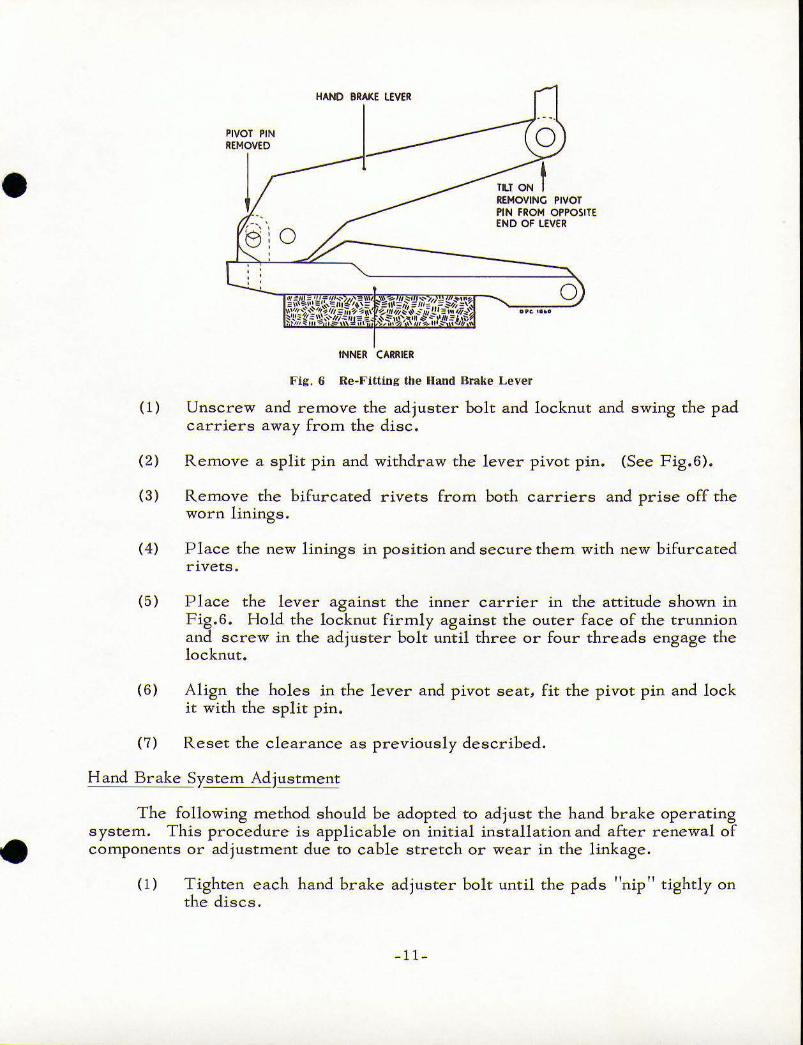
Fig. 6 Re·Fitting the Hand Brake Lever
(1) Unscrew and remove the adjuster bolt and locknut and swing the pad
carriers away from the disc.
(2) Remove a split pin and withdraw the lever pivot pin. (See Fig.6).
(3) Remove the bifurcated rivets from both carriers and prise off the worn linings.
(4) Place the new linings in position and secure them with new bifurcated rivets .
(5) P lace the lever against the inner carrier in the attitude shown in
Fig.6. Hold the locknut firmly against the outer face of the trunnion and screw in the adjuster bolt until three or four threads engage the
locknut.
(6) Align the holes in the lever and pivot seat, fit the pivot pin and lock
it with the split pin.
(7) Reset the clearance as previously described.
Hand Brake System Adjustment
The following method should be adopted to adjust the hand brake operating
system. This procedure is applicable on initial installation and after renewal of
components or adjustment due to cable stretch or wear in the linkage.
(1) Tighten each hand brake adjuster bolt until the pads "nip T! tightly on the discs.
- 11 -
(2) P lace the ha nd brake le ve r in the fu ll y "OF F " posi tion .
(3)
( 4)
Ad jus t the ha nd br ake c a ble in accor dance wi t h the m anufac turer's
instruc t ions , e nsuring t hat there is no p re - load or s l ackness in the
l inkage.
Adj ust the ha nd brake s ind ivid uall y as previous l y descnbed.
No te: Adjus tment to compe nsate fo r pad wear sho uld al ways he m ade at the hand brake unit and at no other ad justme nt point in t he
s ys te m .
PROPEL LOR SHAFT
T ype and make of Joints De troi t Unive r sal.
Th is uni t s ho uld be serviced e ve r y 10 ,000 miles . From be neath t he car it should he com p le tel y removed by taking out the bolts at the front e nd a nd
r e leas ing t he clamp c aps a t the r ear e nd .
At the forwar d e nd of t he s haft remo ve the co ve r a nd gasket b y be nd ing ba c k
the t abs . The a mount of g rea se this jo jnt s hould conta in is 2 ozs. spread evenl y
thro ugho ut the wo r king sur faces. Do no t o verfil l.
At t he r e a r e nd r e le ase the rolle r and bu s hing a s sem blies , freely grease
t he m and r e-assemble .
- 12 -
•
•
•
•
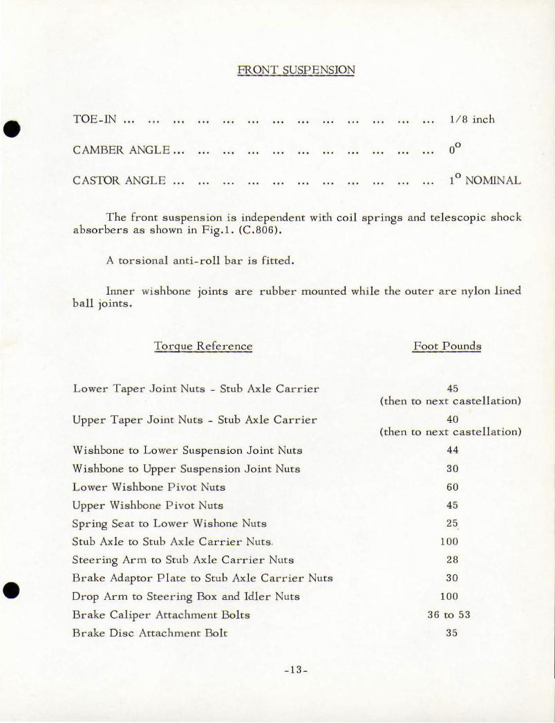
FRONT SUSPENSION
TOE-IN ... ... . .. 1/8 inch
CAMBER ANGLE ... ...
CASTOR ANGL E ... . . . . .. ... ... .., 1° NOMINAL
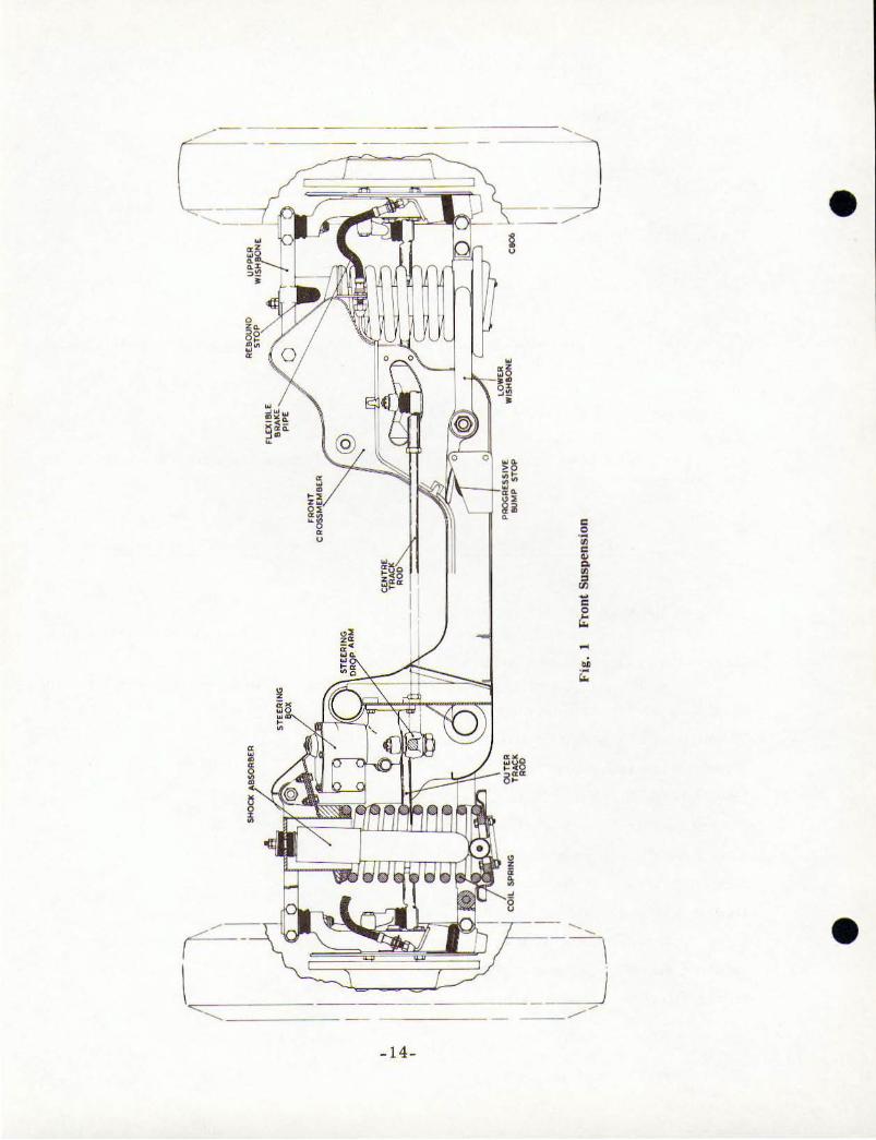
The front s uspension is inde pendent with coil springs and telescopic shock
absorbers as shown in Fig . l . (C.806).
A torsional a nti - roll bar i s fi tted .
Inner wishbone joints are rubber mounted while the o uter are nylon lined ball joints.
Torque Reference
Lower Taper Joint Nuts - Stub Axle Carrier
Upper Taper Joint Nuts - Stub Ax le Carrier
Wishbone to Lower Suspension Joint Nuts
Wishbone to Upper Suspens ion Joint Nuts
Lower Wishbone Pivot Nuts
Upper Wishbone Pivot Nuts
Spring Seat to Lower Wishone Nuts
Stub Axle to Stub Axle Carrier Nuts,
Steering Arm to Stub Axle Carrier Nuts
Brake Adaptor P l ate to Stub Axle Carrier Nuts
Drop Arm to Steering Box and Idle r Nuts
Brake Caliper Attachment Bolts
Brake Disc Attachment Bolt
-13-
Foot Pounds
45
(then to next castell ation)
40
(then to next castellation)
44
30
60
45
25
100
28
30
100
36 to 53
35
/- -- ~~ ~ - ;::::,,;;;~ - - ~ \
l--- -----,J - _/ •
• \l ~~ === ==
- 14-
•
•
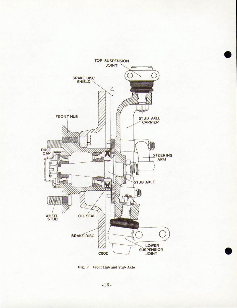
Hub and Stub Axle Assembly
Front Wheel hubs are mo unted on two taper roller bearings with an oi l seal on the inside of t he rear bearing as s hown in F ig.2 (C.802 ). At approved intervals, every 20, 000 miles or 2 years whichever is sooner, as g iven in the
car instruction book. the hub s ho uld be co mpletely re moved and grease packed be twee n t he bearings . T he hexagon dust cap should not contain, o r be loaded.
with any grease.
Brake disc run -out, measured t inch from outside diameter of disc should
not exceed .006 inch . The hub s hould h ave an end float of .00 1 to .003 inch which is achieved by lightly t ightening t he stub ax le nut, with the hub sp inning, then
s lackening to give t he correct e nd float (using a dial indicator) before inserting the split pin.
Brake discs and br ake p ads should have an equal clearance within .010
inch of each other which is contr o lled by the use of shims between the caliper unit and the adaptor plate bolting face .
-15 -
TOP SUSPENSION
JOINT
BRAKE DISC SHIELD
o
F ig . 2 Front Hub and Stub Ax le
-16 -
• o
AXLE
ARM
AXLE
o LOWER
•
•
•
STEERING
ALIGNMENT DA TA TABLE
WHEEL BASE , .. ... 114 inch
FRONT 1RACK ... 53 inch
REAR TRACK ... ... ... 54! inch
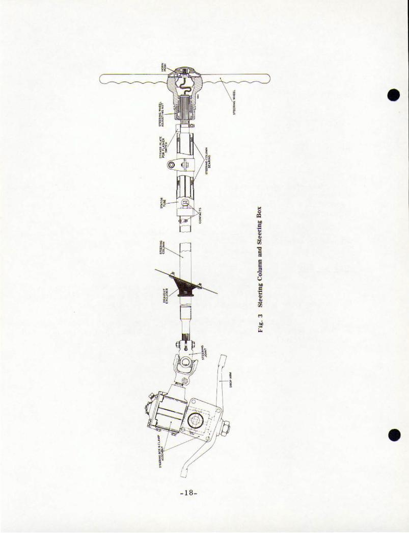
A Marles worm type steering box is fitted and is connected to the steering
column by a universal joint as shown in Fig.3 (R214). The track rods as shown in
Fig.l (C.806) are fitted with ny lon l ined ball joints and the ends have screwed
adjustments.
The steering wheel has a circular locking ring incorporated and a limited
adjustment controlled by circlips , can be made by using a r i ng spanner.
Steering Box
It is important to note that the Marles steering box and the steering clamp
are considered an integral unit and they should not be separated. The clamping bolt and nut have had the hexagon removed to prevent separation.
If it is necessary to take up end play in the steering box, loosen the locknut
on the back of the cover plate, adjust the screw until a ll end float is eliminated and
tighten the locknut .
-l7-
•
• - 18-
•
•
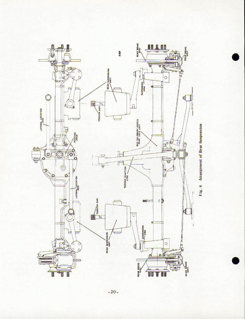
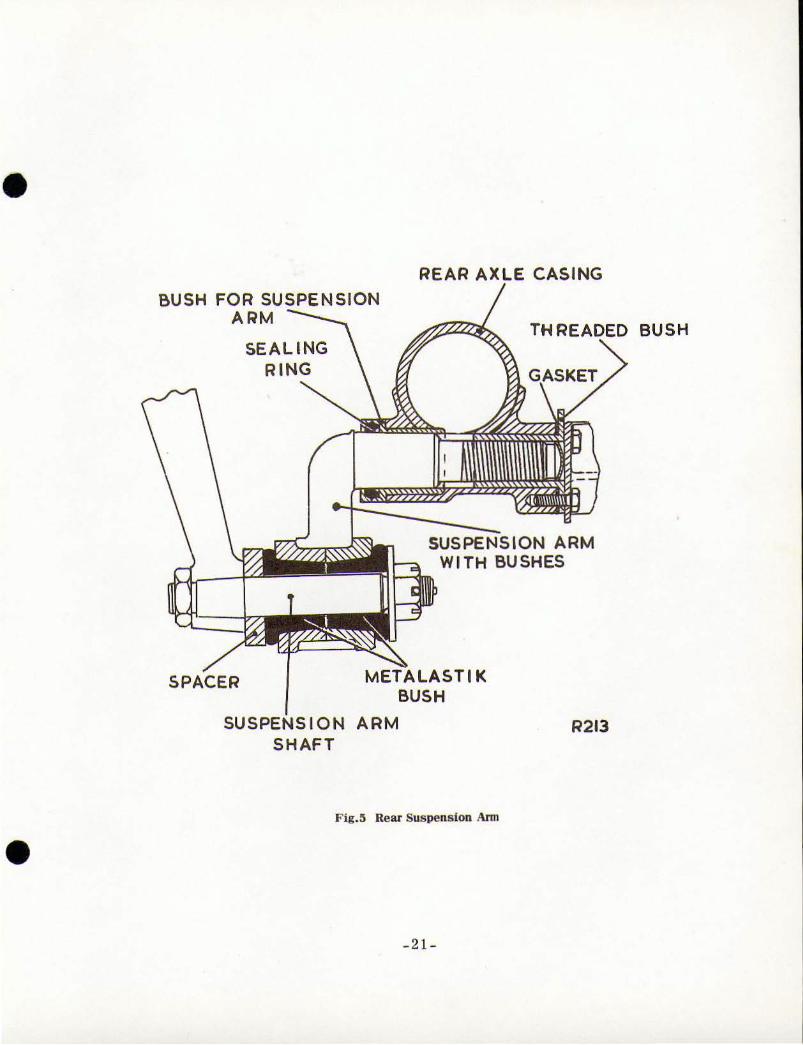
R ear Axle and R ear Sus pension
The rear ax le as s hown in F ig.4 R.189 is t he Salisbury Axle type 4 HA with a rat io of 3 .3 1 to 1 and the suspension arms are rubber mounted as s hown in
Fig .5 R.213.
Al ignme nt of the r e ar ax le, for tracking purposes can be carried o ut by re leasing the t h ree screws on t he rear axle, a t the im media te rear o f the
s us pe ns ion a r ms and revol ving the bush un t i l the correct alignment is obtained.
If the suspension arms a re dismantled or the taper rubber bushes replaced.
they should no t be tightened until the car is on it s whee l s. otherwise they will be
unduly loaded.
It is essential to note t hat an anti-friction washer is fitted by B r is to l Ca r s
be tween the companion flange face and t he oi l s tinger of the Salis bu r y ax le. T his
is to e l iminate a "p inging" noise on drive take-up a nd during gear changes.
REAR SHOCK ABSORBERS
Type 407 .. . ... Armstrong Te lescopic
Type 408 . .. Armstr ong Tele scopic - Se1ectarid e
Arms trong selectaride electricall y controlled absorbers are fitted to the
r ear suspension and are operated b y t he switch on the d ashboard.
This switch must be turned c lock-wise only, as indicated by the arrows on
the bezel between the stations.
The 'SOFT' station is r ecommended for leisurel y cruis ing while hig h s peeds
could dem and t he firm s uspension prov ided fo r b y Station 4. Inte rmediare
degrees of damp ing are p rovided · for by St ations 2 and 3. If by a n c ha nce i t is
desired to go from a 'SOFT ' ride to a fir m ride (4) then t he switch must be turned
through the intermedia te stations, as indicated by the arrows, in order to reach it .
The Switch must not be turned back (ant i - clockwise ) .
NOT E: If the Se lectaride s witch is moved wi th the ig ni t ion off, turn the sw itc h
throug h one full r evo lution with the ig ni tion on before se lecting the des ired setting .
Whe n operating the switch do not hold the pointer in a position between the m arked
stations into wh ich it indexes.
-l9-
i • •
= 0 .-• = • ~
• oil " • • " r -0 -c • l· E • ~ c • t
'" ~
~
~
• ( • •
• -20-
•
•
BUSH FOR SUSPENSION ARM
SEALING
RING
REAR AXLE CASING
THREADED BUSH
SUSPENSION ARM WITH BUSHES
SPACER TIK BUSH
SU SION ARM R213 SHAFT
Fig.5 Rear Suspension Ann
_2 1_
•
•
" . • c "
_~~ " ,.s ~
~ JL'" ~
,
• , •
•
- 23 -
• I ~
•
I • je
• •
· \~ -. j"
-Ir-
I
!e • ,c • • • • • · · :
,
•
• - 25-
•
•
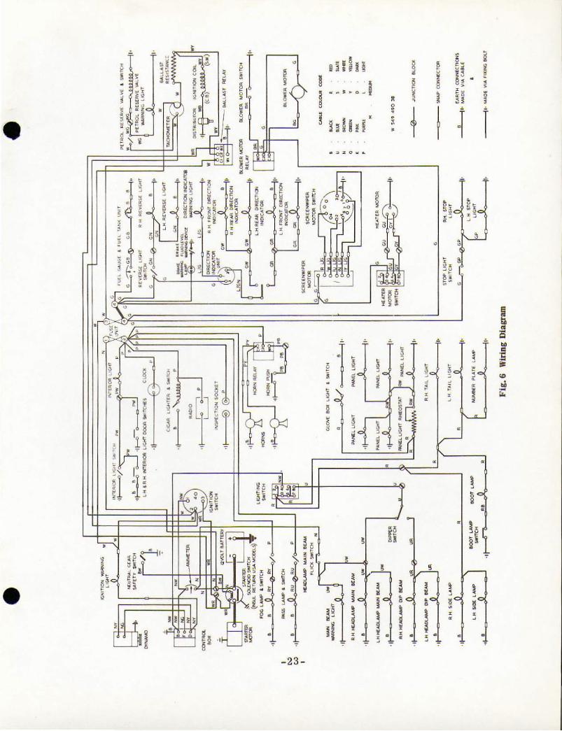
ELECTRICAL SYSTEM Type 407
This is a Lucas 12 volt system . Current is supplied by a large capacity
air cooled generator in conjunction with a voltage and current regulator with
automatic cut_out and a 12 volt 72 ampere battery .
BATTERY, Lucas BT.l1A 40 16437
The battery is ho used in the offside wing bay.
Always keep the top of the battery clean and dry. 'Topping up' the battery is a routine matter and means that the plates in the battery should always be just
covered by adding distilled water to the cells by removing the filler plugs. Various
commercial appliances and methods are used for this procedure, but it is
important not to overfil l. Never use a naked l ight to examine the levels as the
gas given out is inflammable.
No particular period can be give n for the 'toppmg up' of the battery as hot
weather and the conditions of use of the car must be taken into consIderation. It is better to examine the levels frequently.
See that the battery is level and firmly clamped mto posltlOn . The positive
and negative connections are of different sizes and it is not normally possible to
incorrectly a t tach them. Keep the battery connections clean, and smear the
ter mina l s with vase line or petroleum je lly before ar-tac hing the leads, to preve nt
corrosion.
Trickle Charger Socket
An electric supply/feed socke t is mounted on the right hand valance, in the
engine bay, beneath the bonnet. Since it is direct e lectrical contact with the
battery. current may be drawn from t he battery or supplied to it from a 'trickle
charger .
T he object of the tr ickle c harger is to maintain the ba tte ry in a fully charged
state when the car is not in use for le ngth y periods, or whe n the output from the
battery is too great for t he r unning time to permit a fu lly m aintained charge <e.g.
s hort runs in winter months using l amps. starter etc .).
GENERATOR BRUSHES
Brushes should be examined at 10,000 miles, again at 20 ,000 miles, and at
5,000 m iles thereafter.
Brushes tha t are worn short. or are covered with oil, should be replaced to
prevent dam.age to armature. commutator and windings.
-27 -
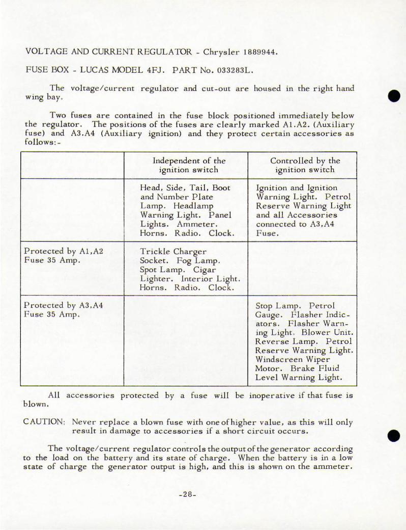
VOLTAGE AND CURRENT REGUL ATOR - Chrys ler 1889944.
FUSE BOX - LUCAS MODEL 4FJ. PART No. 033283L.
T he voltage/curre nt regulator and c ut - o ut are housed 10 t he right ha nd • wing bay .
Two fuses are contained in t he fu se block positioned immediately be low
t he regulator . T he positions of the [uses are clearly marked A l. A2. (Aux i liary
fuse) and A3.A4 (Auxiliary ignition) and they protect certain accessor ies as
fo llows: -
Protected by Al,A2 F use 35 Amp.
Protected by A3,A4 Fuse 35 Amp,
All accessories b lown.
Inde pe nde nt of the Controlled by the ign i tion sw itch ignit ion switch
Head, Side, Tail. Boot Ignition and Ignit ion
and Number P late Warning Light. Petrol Lamp. Headlamp Reserve Warning Light Warning Light. Pane l and all Accessories
L ights. Am meter . connected to A3.A4
Horns . Radio. Clock. Fuse.
Tric kle Charger Socket. Fog Lamp. Spot Lamp. Cigar
Lighter. Interior Li~h t. Horns. Radio. C loc .
Stop Lamp. Petrol
Gauge. Flasher Indic -
ators , F l asher Warn-
ing Light. Blower Unit .
Reverse Lamp , Petrol
Reserve Warning Light.
Windscreen Wiper
Motor. Brake Fluid
Level Warning L ight .
protected b y a fuse will be inope r ative if that fuse is
CAUTIO N: Neve r replace a b lown fuse with o ne of h igher va lue , as this will o nl y
result in damage to accessories i f a s hort circ u it OCCurs. e The vol tage / current regula tor controls the output of the generator according
to t he load on the battery and its state of charge. When the battery is in a low
state of charge the generator outp ut is high, a nd this is shown on the ammeter.
_28_
•
•
WINDSCREEN WIPERS
WIPER ARM - Lucas Part No. 54711438
WIPER BLADE - Lucas Part No. 54711283
The windscreen wiper motor is mounted in the right hand wing bay. The
cable transmits motion to the two wheel - boxes beneath the windscreen, which
operate the wiper arms and blades .
No adjustment or lubrication IS l10rmallynecessaryas all parts are packed with lubricant on assembly.
The windscreen wiper control knob, marked WIPER, on the dashboard has three operating positions.
A thermostatic cut - out switch is built into the wiper motor to prevent over
heating. However, in order to avoid excessive load, the fast speed should only be
used in heavy rain . Never use it in snow or on a drying windscreen without the
use of the screenwash.
HORNS
High Note Low Note
Lucas WT.B18
Lucas WT.61B
Part No, 69090
Part No. 690B7
Dual Windtone horns are fitted beneath the bonnet on each side of the engine
valance.
T he push button in the centre of the steering whee l operates a solenoid relay
switch Lucas 6.RA,Part No .331BBi\ situated in the vicinityofthe right hand horn.
The horns should g ive a long period of service without attention, but should
they become unsatisfactory, check for any loose connections or loose attachment
bol ts before rejecting the horn itself,
LAMPS
tJeadlamps
Home
light into
Lucas Model F, 700
Light Unit (Home) MK.X. Part No.58618.
Lucas 7002 60! 45 W .
This is a sealed beam unit and in the event of a bulb failure the complete
unit must be changed . A h igh beam warning light - RED - is incorporated
the speedometel". When the foot operated headlamp DIPPER SWITCH,
-29-
i s de pressed . it alter native l y switches the headl amp bulb from the lower
power filament to the higher power fi l ament, at which s tage the RED headlamp
warning light is ON . In the dipped position the light is OUT .
Fog Lamp
Spo t L amp
Front Side Lamp and F lasher (C lear)
Rear Side , Stop and combined
Reflector Lamp (R ED)
Rear Flasher Lamp (Am ber )
Reverse Lamp
Rear Number p 1.ate Lamp .
Lueas Mode l SFT.576 . Part No .55 128 . L ueas Bulb No .600 (Yellow) 12v.48w.
Lueas Model SLR .576 . Par t No.55132 .
Lucas Bul b No. 185 12v . 48w.
Lueas Model L 539 . Part No.52333 . Lucas Bul b No.3BD 12v . Twin Fil ament 2 1/6w.
Lueas Model L 551. Part No.53377A .
Lucas Bu lb No .3ao 12v. Twin F ilament 21/6w.
L ueas Mode l L 539 . Part No .52272 . L uea. Bulb 382 12v . 21w.
L ueas Mode l L.488. Part No .52 246B . Lucas Bulb No .38 2. 12\1 , 21w .
Lueas Model 1.534. Part No.5351 8.
Osram Bulb. 12v . 4w .
Instrument Panel Illumi nation
The instr uments are illum inated as fo llows:- o ne bulb in the s peedometer ,
one bulb in the revol ution counter, and two bulbs behind the pane l serve to light
the fue l gauge , ammeter, water temperature gauge and o i l pressure gauge .
T he bulbs are Lucas 907 12v . 2.2w.
T he clock has its own bu lb and the gear selector pus h buttons are i llum inated
by two bulbs.
The bulbs are Phi IJ ips 12829 12v. 2w.
T he panel lig hts are controlle d, in unison, by the rheostat control knob,
marked Ip I, on the dashboard and are wired in circuit with the side lamps .
In additio n the speedometer and revolutio n counter have two bulbs each for
the WARNING LIGHTS.
The bulbs are Lucas 907 12v . 2 .2w .
-30-
•
•
•
•
Courtesy (Interior ) Roof Lamp
Festoon Bul b 12v. 6w.
Door Shut Switch - Lucas Mode l 94 Part No .31175F .
This light is controlled by a switch in both fron t door pillars and the light comes on when a door is opened, and auromaticall y switches off when the doors a r e c losed.
A switch marked le I on the dashboard operates the light when the doors are
closed.
Boot Lamp Lucas Model 474 Part No.052477 Bulb - Riva112v. 6w.
Switch - Lucas Model 94 Part No.035436D
This lamp is mounted centr a lly beneath the too l compartments and is wired in circuit with the s ide l amps . A switch situated under the hinge on the R.H. side
operates the light automatically when the boot door is o pened and the side lamps are on .
Direction Indi cator F lasher
Flasher Unit - Lucas Model FL.5. Pan No.3502 0L.
The F lasher l amps are contro lled by the indicator switch positioned on the left hand side of the steering column, the flasher unit being housed inside the car
behind the dashboard .
When the indicator s witch is in operation _ UP for right t urn, DOWN for
l eft turn - a warning light AMBER embodied into the revolution counter will
continue to flash unti l the lever automatically returns to its neutral position.
Glove Box Lamp Lucas Model L. 550 Part No .52325B Lucas Bulb 987 12v. 2.2w.
Th is light embodied into the top fron t own pus h butlon switch adjacent to t he light. lamps.
Radio
of the g love box is operated by its It is wired in circ ui t with the side
The radio install ation i s classed as an optional extra . T he front speaker I S situated in the roof over the dashboard and the second speaker is fitted into the rear squab shelf.
- 31 -

The ba lanc ing of the s peakers is controlled by a rotary switch, to the right of the radio controls. By rotating the switch fuJI y clockwise the rear
speaker becomes non-operative , and similarly by rotating the switch fully anti
clockwise the front speaker becomes non-operative.
If a radio is not installed at the Works a dummy panel takes its place on
the dashboard , the speaker gri lle in the roof and rear squab are fit ted but not the speakers . The roof aer ia l is not fitted but the lead- in from the roof to the
dashboard is in pos i tion .
-3 2-
•
•
•
•
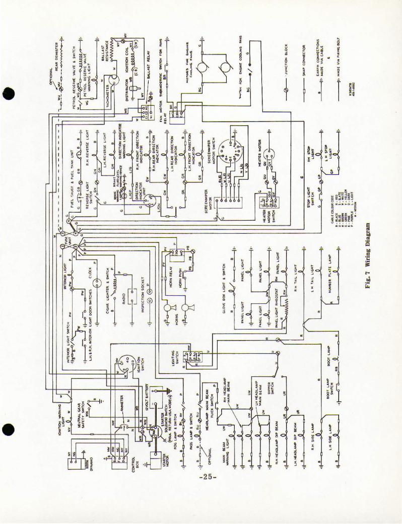
ELECTRICAL SYSTEM - Type 408
T his is a Lucas 12 volt system. Current is s uppl ied by a large capacity
a ir cooled generator in con jtu1ction with a voltage a nd current regul ator with
automat ic cut-out a nd a 12 vol t 72 ampere battery.
BATTERY, L ucas BT. IIA 4016437
The battery is housed in the offside wing bay.
Always keep the top of the battery clean and dry. 'Topping up ' the battery 15 a routine matter and means that the pl ates in the battery should a lways be just
covered by adding disti lled water to the cells by removing the fi ller p l ugs . Various commercial appliances and methods are use d for this procedure, but it is important not to overfil l. Never use a naked light to examine the levels as the
gas given out is inflammable .
No p art ic ular pe riod can be given for t he 'topping Upl of the batter y as hot
weather and the conditions of use of the car must be take n into consideration. It
i s better to examine the levels frequently.
See cl1at the battery is level and fir m l y clamped into posltJOn . The positive
and negative connections are of different s izes and i t is not normally possible to incorrectly attach them . Keep the ba ttery c onnect ions clean. and smear the
terminals with vasel ine or petrole um je Jl y be fore attaching the lea ds . to pre ven t
corrosion.
Trickle Charger Socket
An e lectric suppl y/feed socket is mounted on the right hand va lance, in the engine bay, beneath the bonnet. Since it is direct e lectrical contact with t he
battery, current may be drawn from the battery or supplied to it from a trickle
charger.
The object of the trick le charger is to maintain the battery in a fully c harged state when the car is no t in use for l e ngthy periods. or when the o utpu t from the battery i s too great for t he running tim e to permit a fu ll y m aintained c harge (e.g. short runs in winte r month s us ing lamps, starter etc .) .
GENERA10R BRUSHES
Brushes should be examined at 10.000 miles. again at 20,000 m iles, and at
5.000 mi les therearter.
Brushes that are worn short, or are covered with oiL should be repl aced to prevent damage to armature, commutator and windings .
- 33 -
VOLTAGE AND CURRENT REGULATOR - C hrysler 1889944
FUSE BOX - LUCA S MODE L 4FJ. PART No . 033283L .
T he voltage/current regulator and cut-Out are hou sed in the right hand
wing bay.
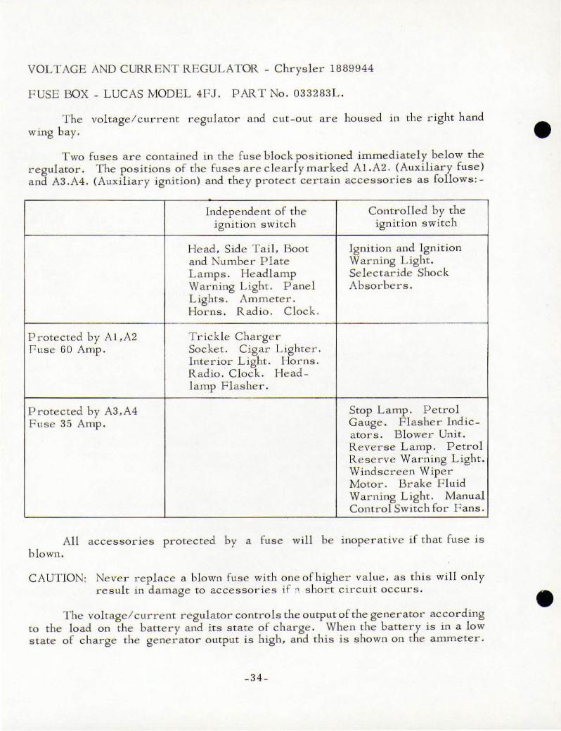
Two fuses are contained in t he fuse bloc k pos itioned immediatel y below the
regulator. The positions o f the fuses are clearl y m arked Al.A2 . (Auxi lia r y fuse)
a nd A3 .A4. (Auxil iary ignition) and they p r otect certain accessories as rallows:-
Independent of the Contro lled by the
ignition sw itch ignitio n switch
J-Iead , Side TaiL Boot jgnition and Ig nition
and Nu mbe r P late Warni ng Light.
L amps. Head lamp Select a r ide Shock
Warning Light . Panel Absorbe rs .
Lights. Am meter.
Horns . Radio . C lock.
Protected by A l,A2 Tr ick le Cha rge r
Fuse GO Amp. Soc ket. Cigar Lighter.
Interior Light. Horns.
Radio. Clock . Head -lamp Flasher.
Protected by A3,A4 Scop L amp. Pet r o l
Fu s e 35 Amp. Gauge . F l asher ind ic-
ators. Blower Unit.
R e vers e Lamp. Petrol
R eserve Warning L ight.
Windsc[·ee n Wiper
Moto r . Brake r:; luid
Warni ng Lig ht. Manual
Contro l Switc h for F ans .
All blown.
accessories protected by a fu se will be inope r ative if that fuse is
CAUTION: Never replace a blown fuse wi th oneof higher value. as this wi ll o nly
result in damage to accessories if :1 short circuit occ ur s .
The voltage/ current regulator controls the output of the ge nerator accor ding
co t be load on the batte r y and it s state of c harge . When the ba ttery is in a low
state of c harge the generator o utput is h igh. a nd this is shown on the ammeter.
_34 _
•
•
•
•
WINDSCREEN WIPERS
WIPER ARM - Lucas Part No. 54711438
WIP ER BLADE - Lucas Part No. 54711283
The windscreen wiper motor is mounted in the right hand wing bay. The
cable transmits motion to the two wheel - hoxes beneath the windscreen, which
operate the wiper arms and blades.
No adjustment or lubrication is normally necessary as all parts are
packed with lubricant on assembly.
The windscreen wiper control knob. marked WIPER. on the dashboard has three operating positions .
A thermostatic cut-out switch is built into the wiper motor to prevent over
heating . However, in order to avoid excessive load, the fast speed should only be
used in heavy rain. Never use it in snow or on a drying windscreen without the
use of the screenwash.
HORNS
High Note Low Note
Lucas WT.61S
Lucas WT.61B
Dual Windtone horns are mounted be hind the grille.
Part No. 69090
Part No. 69087
The push button in the centre of the steering wheel operates a solenoid
relay switch Lucas 6.RA.Part No.331B8A situated in the vicinity of the right hand
horn.
The horns should give a long period of service without attention, but should
they become unsatis factory, check for any loose connections o r loose attachment
bolts before rejecting the horn itself.
Headlamps
Outer
Inner
7 inch dia.
Light Unit.
LAMPS
Lucas Model F700 MK.X. Part No.58G18
Lucas 7002 60/45W. Part No .54521060 .
5i dia. Lucas Model 5i dia. 1 A Part No .58990.
Light Unit. Lucas Part No .54520172.
-35 -
These are sealed beam un its and in the event of a lamp fa ilure t he com plete light unit m ust be changed . A h igh beam warning light _ RED - is incorporated
into the speedometer. When the foot operated head lamp DIPPER SWITCH,
is depressed, it a lterna tively switches the outer headlamp light fro m the lower powe r fi lament to the higher power filam ent, the inner l amps com e into
operation a nd the RE D warning l ight is ON . In the dipped position the inner e l amps are o ut, the o uter lamp s are on t he lower powe r fi lament, a nd the warning
light is OUT.
Fog Lamp. Spot Light.
)
)
Front Side Lamp
& F lasher (Clear) .
Rear Lamp
C l uster. (Stop,
Tail & Flasher).
Reverse L a mp
Rear Nu mber
P late Lamp.
Lamps optional. Switches provided on dashboard.
Lucas Model 584 R.H . Part No.52506 . L .H . Part No.52507 .
Lucas Bulb No.222 (Side) Lucas Bulb No.382 (F l asher).
Lucas Model L 684 Part No .53283 . Lucas Bul b No.380 (Stop & Tail) . L ucas Bu lb No.382 (Flasher) .
Luca s Model 595 Part No.52567.
Lucas Bulb No.382.
Lucas Model 534 . Part No.53518.
Osra m Bul b. 12v. 4w.
Instrument Panel Illumination
The instruments are illuminated as fo11ows:- one hldb in the speedometer , one bu lb in the revolu tion counter, and two bu lbs behind t he panel serve to light t he fuel gauge, ammeter , water temperature gauge and o il pressure gauge.
The bul bs are Lucas 987 12v. 2.2w.
The clock has i ts own bu l b and the gear selector pus h buttons are ill uminated b y two bulbs .
The bulbs are Phillips 12829 12v. 2w.
The panel l ights are controHed , in unison. by the r heosta t control knob. m a rked 'P ', on the dashboard and are wired in c irc ui t with the side la mps .
In addition the speedomete r and r evolution counter have t wo bulbs each for the WN,NING LJGHTS.
T he bulbs are Lucas 987 12v. 2.2w .
- 36 _
•
•
•
Courtesy (Interior) Roof Lamp
Festoon Bulb 12v . 6w.
Door Shut Switch - Lucas Model 94 Part No.3 1175F .
T his light is cont rolled by a switch in both fro nt door pillars a nd the l ight c omes on when a door is opened, and au toma tica ll y switches off when the doors are closed.
A switch marked IC 1 on the dashboard operates the light when the doors are closed.
Boot Lamp Lucas Model 474 Part No .052477
Bulb - Rival 12v .6w. Switch - Lucas Model 94 Part No.035436D
The lamp is mounted centrally beneath the tool compartments and is wired in circuit with the side lamps . A switch situated under the hinge on the R.H. side
ope-rates the light automatically when the boot door is opened and the side lamps are on.
Direction Indicator & He adlamp Flashe r
F lasher Unit - Lucas Model FL .5. Part No.35 020L.
The Flasher l a mps are controlled by the indicator switch positioned on the l eft hand side of the steering column, the flasher unit being housed inside the car
behind the dashboard.
When the indicator switch is in operation - UP for right turn, DOWN for left turn - a warning l ight AMBER embodied into the revolution counter will continue to flash until the lever automatically returns to its neutral position. A
fore and aft movement of the lever will flash all four headlamps.
Glove Box Lamp Lucas Mode l L.550 Part No .52325B
Lucas Bulb 987 12v. 2 .2w.
This light embodied i nto the top front of the g love box is operated by its own push button switch adjacent to the light. It is wired in c ircuit with the side
l amps .
Radio
T he radio i nstall ation is classed as an optional extra. The front speaker is situated in the roof over the dashboard and the second speaker is fitted into the rear squab shelL
- 37-

The bal anc ing of the speakers 15 controIJed by a rotary switch, to the r jght of the radio control s . By ro tating the switch fu ll y clockwlse the
r ear speaker becomes non-operat ive, and similarly by rotating the switch rully
anti-clockwise the rront speaker becomes non_operative .
If a r adio 1S not installed at the Works a dummy pane l takes ,Its p lace on the dashboard, the s peaker grille in the roof and rear squab are fit ted but not
the speakers.
- 38 -
•
•
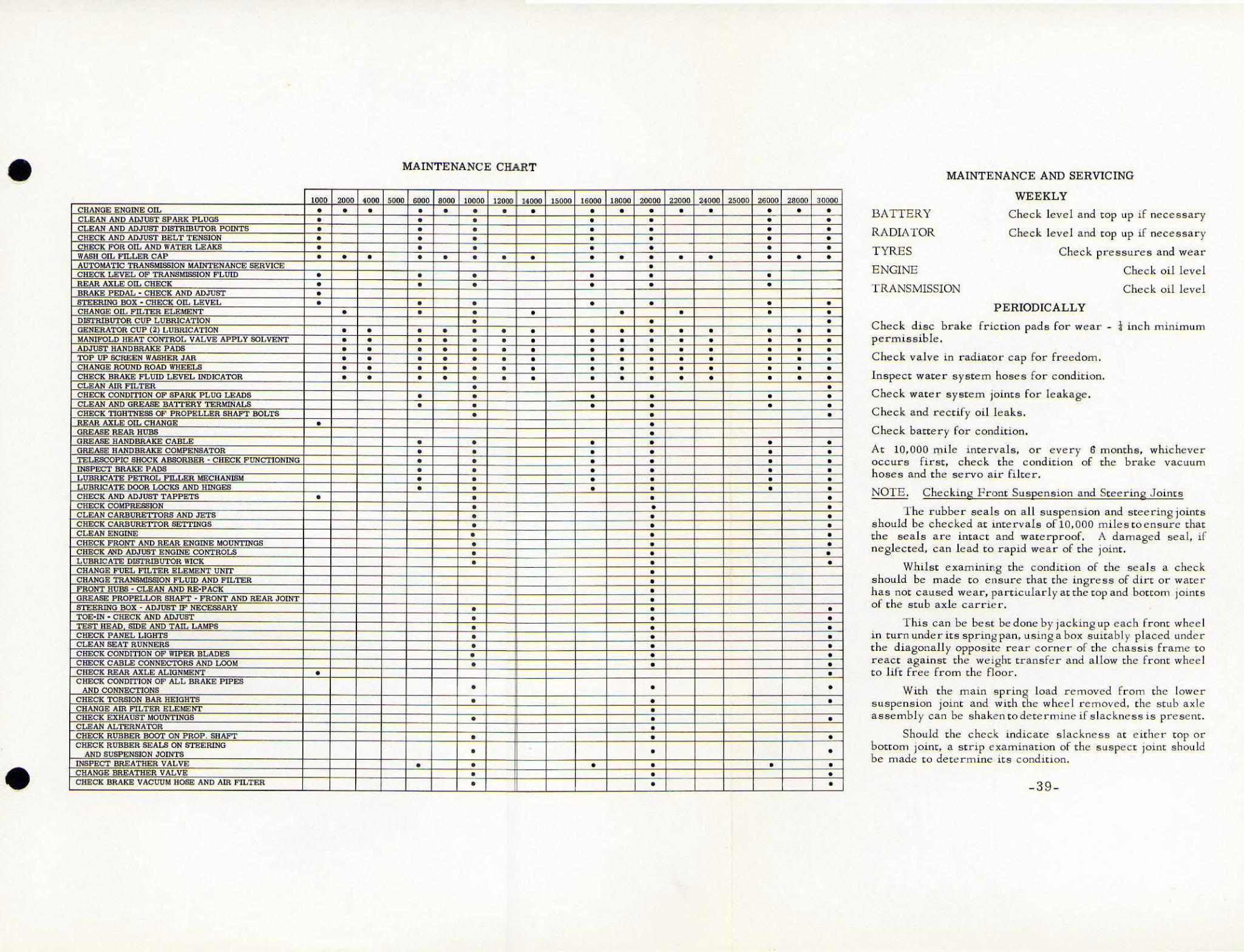
• MAINTENANCE CHART
• • •
• •
• • •
MAINTENANC E AND SERVICING
WEEKLY
BATTERY
RADIATOR
TYRES
ENGINE
TRANSMISSION
Check disc brake permissible,
Check level and top up if nece s sary
Check level and top up if necessa r y
Check pressures and wear
Check oil level
Check oil level
P ERIODICALLY
r riction pads for wear - i inch minimum
Check valve in radiator cap for freedom.
Inspect water system hoses for condition.
Check water systelll joints for leakage.
C heck and rectify oil leak s.
Check battery for condition.
At 10,000 mile intervals, or every 6 months, whicheve r
occurs first , check the condition of the brake vacuum
h oses and t he servo air fi lter.
NOTE . Checking Front Suspension and Steering J oints
T he rubbe r seals on a ll suspension and steerin g joints
should be checked at lntervaLs of 10, 00 0 miles t o ensure that
the sea ls are intact and waterproor. A damaged sea l, if
n eglected, can lead to rapid wear of the joint.
Whilst examining the condition of the sea ls a check
shou ld be made to e nsure that the ingress of dirt or water
has not caused wear, particularly at the top and bottom joints
of the stub axle carrier .
T his c an be best be done by jacking up eac h front whee l
in turn under its spring pan . using a box suitably placed under
the diagonall y opposite rear corner of the chassis frame to
react against the we ight transfer and a l low the front whee l
to lift free from the floor .
With the main spring load removed from the lower
suspe nsion joint and with the wheel r emoved , the stub axle
assembly can be shake n to determine if s lackness is present.
Should the chec.k indicate slackness at e ither top or
bottom joint, a st r ip exam ination of the suspect joint should
be made to dete rmine its condition,
-39 -
•
•
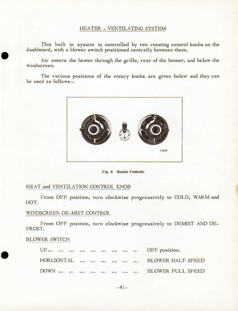
HEATER - VENTILATING SYSTEM
This built in system is controlled by two rotating control knobs on the
dashboard, with a blower switch positioned centrally be tween them .
Air enters the heater through the grille. rear of the bonnet. and below the windscreen.
The various posltlOns of the rotary knobs are given below and they can be used as follows:-
" ""
Fig. 6 lIeater Controls
HEAT and VENTILATION CONTROL KNOB
From OFF position. turn clockwise progressively to COLD. WARM and HOT.
WINDSCREEN DE-MIST CONTROL
From OFF position, turn clockwise progressively to DEMIST AND DE FROST.
BLOWER SW ITCH
UP ...
HORIZONTAL
DOWN ... ...
.. .
-41-
OFF position.
BLOWER HALF SPEED
BLOWER FULL SPEED
•
Thus, the system can be used normally. with the blower switch OF F, boosted to a second stage with the blower switch horizontal, and boosted further
to a third stage with the blower switch down.
COLD AIR SUPPLY
A lever s i tuated centrally below the dashboard controls the supply of cold fresh air into the car. This is a direct air stream which enters the car at the
grille just forward of the windscreen. It is completely independent of the heater system and blower.
Any position from shut, lever fully LEFT, to open, lever fully RIGHT, can be used depending on the flow of a i r required.
The use of the opening rear quarter lights in conjunction with the heate r and
ventilating system is recommended, wherever possible , for air circulation.
- 42 -
•
•