Embed Size (px)
Citation preview
Brazilian Hybrid Electric Fuel Cell Bus
P.E.V. de Miranda, E.S. Carreira
This document appeared in
Detlef Stolten, Thomas Grube (Eds.):18th World Hydrogen Energy Conference 2010 - WHEC 2010Parallel Sessions Book 6: Stationary Applications / Transportation ApplicationsProceedings of the WHEC, May 16.-21. 2010, EssenSchriften des Forschungszentrums Jülich / Energy & Environment, Vol. 78-6Institute of Energy Research - Fuel Cells (IEF-3)Forschungszentrum Jülich GmbH, Zentralbibliothek, Verlag, 2010ISBN: 978-3-89336-656-9
Brazilian Hybrid Electric Fuel Cell Bus
P.E.V. de Miranda*, E.S. Carreira, Hydrogen Laboratory – Coppe-Federal University of Rio de Janeiro, Brazil
Abstract The first prototype of a hybrid electric fuel cell bus developed with Brazilian technology is unveiled. It is a 12 m urban-type, low-floor, air-conditioned bus that possesses three doors, air suspension, 29 seats and reversible wheelchair site. The bus body was built based on a double-deck type monoblock vehicle that is able to sustain important load on its roof. This allowed positioning of the type 3 hydrogen tanks and the low weight traction batteries on the roof of the vehicles without dynamic stabilization problems. A novel hybrid energy configuration was designed in such a way that the low-power (77 kWe) fuel cell works on steady-state operation mode, not responding directly to the traction motor load demand. The rate of kinetic energy regeneration upon breaking was optimized by the use of an electric hybrid system with predominance of batteries and also by utilizing supercapacitors. The electric-electronic devices and the security control softwares for the auxiliary and traction systems were developed in-house. The innovative hybrid-electric traction system configuration led to the possibility to decrease the fuel cell power, with positive impact on weight and system volume reduction, as well as to significantly decrease the hydrogen consumption.
1 Introduction
Several hydrogen fuel cell buses have been built and tested throughout the world up to the present. The most significant field trial was the European demonstration project CUTE – Clean Urban Transport for Europe [1]. The CUTE project involved the operation of 27 similar buses effectively transporting people in regular urban lines in ten different European cities within a two-year span period. This was followed by the operation of six more buses of the same kind associated to projects in Iceland and Australia and three additional ones in China. Other than the great amount of technical assessment it allowed on the fuel cell bus technology, these trials have also brought knowledge on the good public acceptance of this advanced and environmentally friendly urban transport option and on the accumulation of expertise on producing, distributing, storing and servicing high purity hydrogen for large scale energy purposes. However, several instructive drawbacks were also withdrawn from the analysis made. The powerful, heavy and costly fuel cells used imposed an important penalty on fuel consumption. The average hydrogen consumption in the CUTE project was equal to 24.6 kg H2/100 km. Important technical features of the CUTE technology have contributed for this high hydrogen consumption. More recent energy accumulators have allowed the design of energy hybridized power trains that have shown to be an important factor for the bus fuel
* Corresponding author, email: [email protected]
Proceedings WHEC2010 253
economy. Consequently, other hybrid fuel cell buses reached much better fuel economies than that of the CUTE project [2 (6), 3 (8)]. Although the conceptual work of a Brazilian urban fuel cell bus has started many years ago, back in 1999, in Coppe, a graduate centre of the Federal University of Rio de Janeiro, it was since the beginning idealized as an energy hybrid power train system, hardly achievable with that time’s energy accumulators technology. These ideas matured in 2004 into the present development project that effectively started in 2005 with the concept of a 12m urban low-floor bus that should possess a low power fuel cell to work in steady-state condition, recharging a bank of traction batteries, which in turn should also be recharged by connection to the grid, in a plug-in bus version, and make use of an efficient regenerative breaking technology. The great majority of sub-systems and components composing the power train and auxiliary systems for this fuel cell bus were conceived, developed and fabricated in Brazil and is being unveiled herein for the first time. The objective of the present work is to demonstrate the actual feasibility of an innovative hydrogen fuel cell bus for urban use employing a stationary operation type low-power PEM fuel cell in a specially engineered hybrid plug-in power train.
2 Technical Features
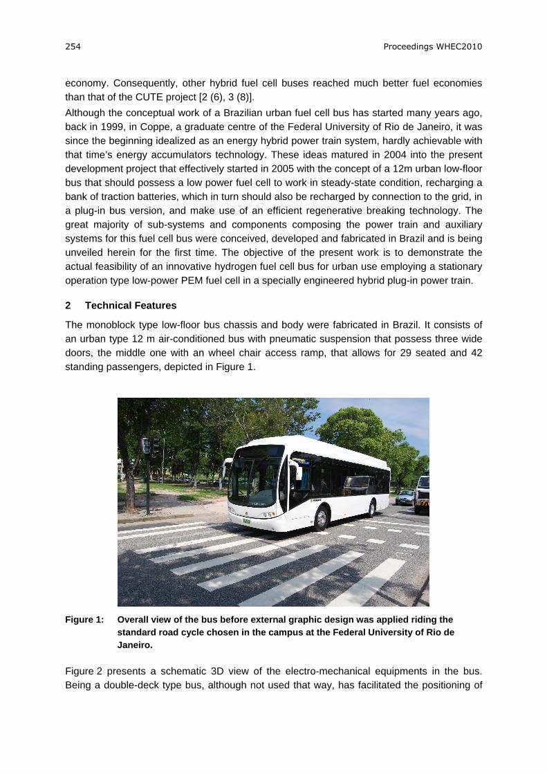
The monoblock type low-floor bus chassis and body were fabricated in Brazil. It consists of an urban type 12 m air-conditioned bus with pneumatic suspension that possess three wide doors, the middle one with an wheel chair access ramp, that allows for 29 seated and 42 standing passengers, depicted in Figure 1.
Figure 1: Overall view of the bus before external graphic design was applied riding the
standard road cycle chosen in the campus at the Federal University of Rio de Janeiro.
Figure 2 presents a schematic 3D view of the electro-mechanical equipments in the bus. Being a double-deck type bus, although not used that way, has facilitated the positioning of
254 Proceedings WHEC2010
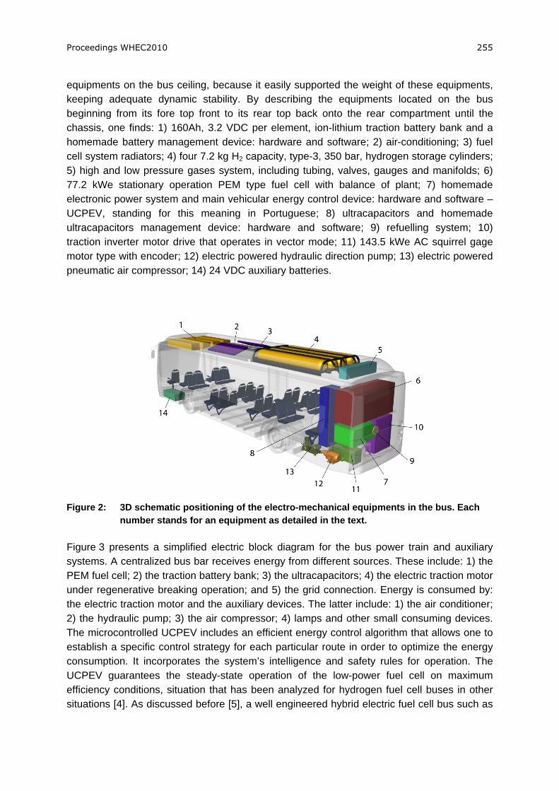
equipments on the bus ceiling, because it easily supported the weight of these equipments, keeping adequate dynamic stability. By describing the equipments located on the bus beginning from its fore top front to its rear top back onto the rear compartment until the chassis, one finds: 1) 160Ah, 3.2 VDC per element, ion-lithium traction battery bank and a homemade battery management device: hardware and software; 2) air-conditioning; 3) fuel cell system radiators; 4) four 7.2 kg H2 capacity, type-3, 350 bar, hydrogen storage cylinders; 5) high and low pressure gases system, including tubing, valves, gauges and manifolds; 6) 77.2 kWe stationary operation PEM type fuel cell with balance of plant; 7) homemade electronic power system and main vehicular energy control device: hardware and software – UCPEV, standing for this meaning in Portuguese; 8) ultracapacitors and homemade ultracapacitors management device: hardware and software; 9) refuelling system; 10) traction inverter motor drive that operates in vector mode; 11) 143.5 kWe AC squirrel gage motor type with encoder; 12) electric powered hydraulic direction pump; 13) electric powered pneumatic air compressor; 14) 24 VDC auxiliary batteries.
Figure 2: 3D schematic positioning of the electro-mechanical equipments in the bus. Each
number stands for an equipment as detailed in the text.
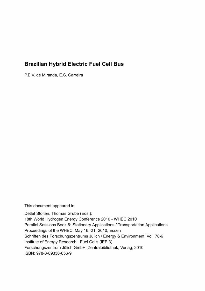
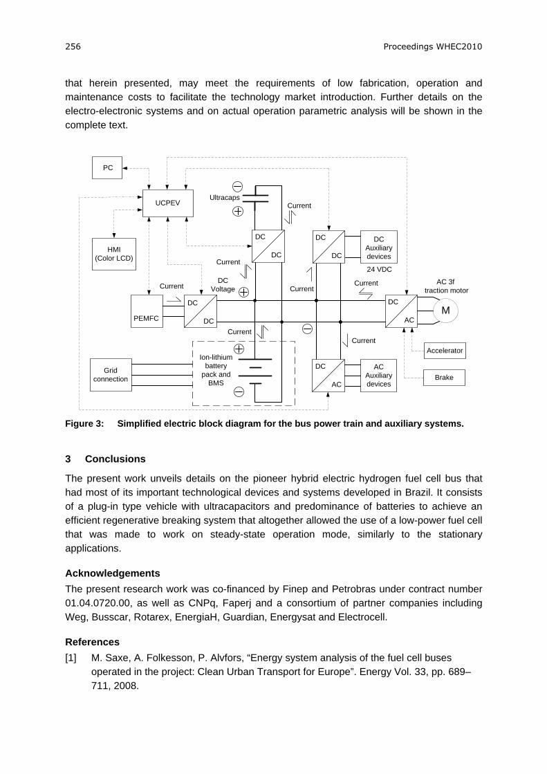
Figure 3 presents a simplified electric block diagram for the bus power train and auxiliary systems. A centralized bus bar receives energy from different sources. These include: 1) the PEM fuel cell; 2) the traction battery bank; 3) the ultracapacitors; 4) the electric traction motor under regenerative breaking operation; and 5) the grid connection. Energy is consumed by: the electric traction motor and the auxiliary devices. The latter include: 1) the air conditioner; 2) the hydraulic pump; 3) the air compressor; 4) lamps and other small consuming devices. The microcontrolled UCPEV includes an efficient energy control algorithm that allows one to establish a specific control strategy for each particular route in order to optimize the energy consumption. It incorporates the system’s intelligence and safety rules for operation. The UCPEV guarantees the steady-state operation of the low-power fuel cell on maximum efficiency conditions, situation that has been analyzed for hydrogen fuel cell buses in other situations [4]. As discussed before [5], a well engineered hybrid electric fuel cell bus such as
Proceedings WHEC2010 255
that herein presented, may meet the requirements of low fabrication, operation and maintenance costs to facilitate the technology market introduction. Further details on the electro-electronic systems and on actual operation parametric analysis will be shown in the complete text.
DC
DC
DC
AC
AC 3f traction motor
Ion-lithium battery
pack andBMS
PEMFC
DC
AC
AC Auxiliarydevices
DC
DC
DC Auxiliarydevices
DC Voltage
24 VDC
Current
Current Current
UCPEV
M
Current
Current
DC
DCCurrent
UltracapsCurrent
HMI(Color LCD)
PC
Accelerator
BrakeGrid
connection
Figure 3: Simplified electric block diagram for the bus power train and auxiliary systems.
3 Conclusions
The present work unveils details on the pioneer hybrid electric hydrogen fuel cell bus that had most of its important technological devices and systems developed in Brazil. It consists of a plug-in type vehicle with ultracapacitors and predominance of batteries to achieve an efficient regenerative breaking system that altogether allowed the use of a low-power fuel cell that was made to work on steady-state operation mode, similarly to the stationary applications.
Acknowledgements The present research work was co-financed by Finep and Petrobras under contract number 01.04.0720.00, as well as CNPq, Faperj and a consortium of partner companies including Weg, Busscar, Rotarex, EnergiaH, Guardian, Energysat and Electrocell.
References [1] M. Saxe, A. Folkesson, P. Alvfors, “Energy system analysis of the fuel cell buses
operated in the project: Clean Urban Transport for Europe”. Energy Vol. 33, pp. 689–711, 2008.
256 Proceedings WHEC2010
[2] H. Ishitani, “Vehicle test results, a JHFC Program activity report, retrieved at: http://www.jhfc.jp/data/seminar_report/04/pdf/05_h17seminar_e.pdf, March 2010.
[3] K. Chandler, L. Eudy, “Alameda-Contra Costa Transit District (AC Transit), Fuel Cell Transit Buses: Preliminary Evaluation Results. Technical report no. 560-41041, Golden, Colorado, National Renewable Energy Laboratory, 2007. Retreived at: http://www.nrel.gov/hydrogen/pdfs/41041.pdf, March 2010.
[4] Liangfei Xu, Jianqiu Li, Jianfeng Hua, Xiangjun Li, Minggao Ouyang, “Optimal vehicle control strategy of a fuel cell/battery hybrid city bus”. International Journal of Hydrogen Energy, Vol. 34, pp. 7323 – 7333, 2009.
[5] Jamie Ally, Trevor Pryor. “Accelerating hydrogen implementation by mass production of a hydrogen bus chassis”. Renewable and Sustainable Energy Reviews, Vol. 13, pp. 616–624, 2009.
Proceedings WHEC2010 257