Embed Size (px)
Citation preview
Journal of Thermal Science Vol.23, No.1 (2014) 6067
Received: October 2013 Jaye Koo: Professor This work was supported by the National Research Foundation of Korea (NRF) grant funded by the Korean Government (MEST) (NRF-2011-0015435 and NRF- 2012M 1A3A3A02033146)
www.springerlink.com
DOI: 10.1007/s11630-014-0677-7 Article ID: 1003-2169(2014)01-0060-08
Breakup Structure of Two-phase Jets with Various Momentum Flux from a Porous Injector
Inchul Lee1, Dohun Kim1 and Jaye Koo2
1. Graduate Student, Korea Aerospace University, Goyang, Republic of Korea
2. School of Aerospace and Mechanical Engineering, Korea Aerospace University, Goyang, Republic of Korea
© Science Press and Institute of Engineering Thermophysics, CAS and Springer-Verlag Berlin Heidelberg 2014
Spray structure and atomization characteristics were investigated through a comparison of a porous and a shear
coaxial injector. The porous injector shows better atomization performance than the shear coaxial injector. To in-
crease atomization performance and mixing efficiency of two-phase jets, a coaxial porous injector which can be
applicable to liquid rocket combustors was designed and tested. The characteristics of atomization and spray from
a porous and a shear coaxial injector were characterized by the momentum flux ratio. The breakup mechanism of
the porous injector is governed by Taylor-Culick flow and axial shear forces. Momentum of injected gas flow
through a porous material which is composed of sintered metal is radically transferred to the center of the liquid
column, and then liquid column is effectively broken up. Although the shapes of spray from porous and shear co-
axial jets were similar for various momentum ratio, spray structures such as spray angle and droplet sizes were
different. As increasing the momentum flux ratio, SMD from the porous injector showed smaller value than the
shear coaxial injector
Keywords: Porous injector, Shear coaxial injector, Breakup mechanism, Momentum flux ratio
Introduction
Combustion efficiency and stability are ultimately de-cided by the configuration of the injector type and at-omization performance. Generally, combustion efficiency and stability are determined by the homogeneous droplet distributions and the dynamic process of spray breakup. There are many injectors applied to liquid rocket com-bustors. The impinging injector and shear coaxial injector have affordable expense to design injector assembly, however, these injector have combustion instability and a disadvantage in throttle ability. Nowadays, the swirl co-axial injector is extensively used in liquid rocket com-bustors. Swirl injector reduces combustion instability and increase mixing efficiency, however, swirl coaxial injec-
tors have some large pressure drop characteristics about 0.3 ~ 0.5 and are complex processes to make accurate injector tolerances.
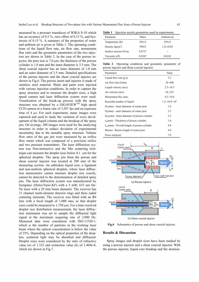
Porous materials have many advantages, such as the cooling of the injector plate, stable operation of the combustion process and the optimization of the injector pressure drop. Therefore this material has been used in the industrial field including in rocket injectors and heat exchangers. The preferable features of porous injectors are classified with many advantages. First, the initial contact area is increased by more than 100%. Second, turbulent vortex at near the injector face increases at-omization. Third, throttling is more stable than with shear coaxial injectors. Fourth, it can dampen the acoustic insta bility. Porous injectors were presented by Bazarov[1]-
Inchul Lee et al. Breakup Structure of Two-phase Jets with Various Momentum Flux from a Porous Injector 61
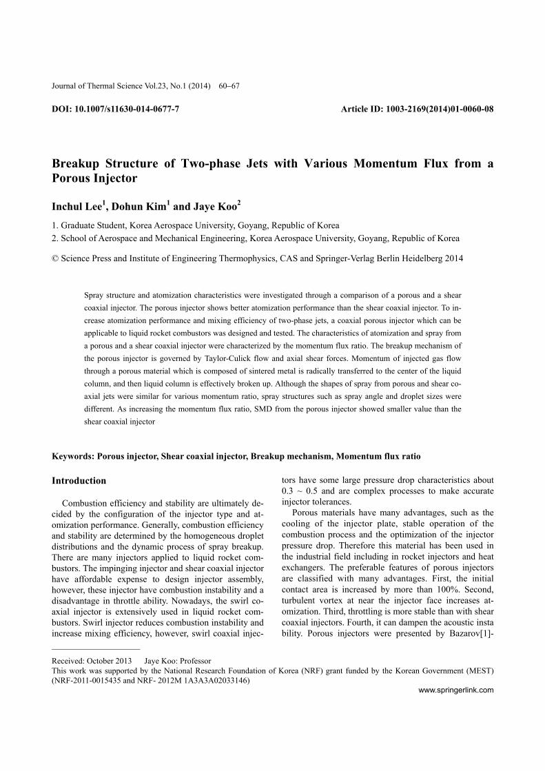
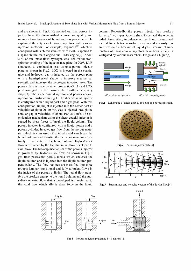
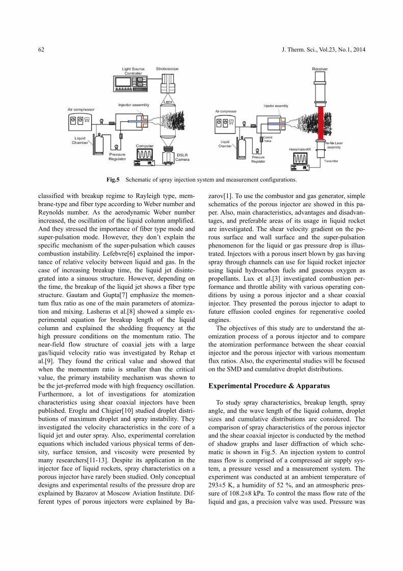
and are shown in Fig.4. He pointed out that porous in-jectors have the distinguished atomization quality and mixing characteristics of liquid and gas propellants. He explained three types of porous injectors with various injection methods. For example, RigimeshTM which is configured with sintered stainless wire mesh is applied to a space shuttle main engine and RL10 engine[2]. About 20% of total mass flow, hydrogen was used for the tran-spiration cooling of the injector face plate. In 2008, DLR conducted to combustion tests using a porous injector plate as shown in Fig.2. LOX is injected in the coaxial tube and hydrogen gas is injected on the porous plate with a hemispherical shape to improve mechanical strength and increase the hydrogen injection area. The porous plate is made by sinter bronze (CuSn11) and LOX post arranged on the porous plate with a periphery shape[3]. The shear coaxial injector and porous coaxial injector are illustrated in Fig.1. The shear coaxial injector is configured with a liquid post and a gas post. With this configuration, liquid jet is injected into the center post at velocities of about 20~40 m/s. Gas is injected through the annular gap at velocities of about 100~200 m/s. The at-omization mechanism using the shear coaxial injector is caused by shear forces to break the liquid column. The porous injector is configured with a liquid nozzle and a porous cylinder. Injected gas flow from the porous mate-rial which is composed of sintered metal can break the liquid column and transfer the radial momentum effec-tively to the center of the liquid column. Taylor-Culick flow is explained by the fact that radial flow developed to axial flow. The breakup mechanism of the porous injector is governed by Taylor-Culick flow. As shown in Fig.3, gas flow passes the porous media which encloses the liquid column and is injected into the liquid column per-pendicularly. The flow regimes are classified into three groups: laminar, transitional and fully turbulent flows in the inside of the porous cylinder. The radial flow trans-fers the breakup energy to the liquid column and the sub-sidiary or extra flow that is developed is transferred to the axial flow which affects shear force in the liquid
column. Repeatedly, the porous injector has breakup forces of two types. One is shear force, and the other is radial force. Also, turbulence on the liquid column and inertial force between surface tension and viscosity has an effect on the breakup of liquid jets. Breakup charac-teristics of shear coaxial injectors have been widely in vestigated by various researchers. Frago and Chigier[5]
Fig.1 Schematic of shear coaxial injector and porous injector.
Fig.2 Porous injector plate[3].
Fig.3 Streamlines and velocity vectors of the Taylor flow[4].
Fig.4 Porous injectors presented by Bazarov[1].
62 J. Therm. Sci., Vol.23, No.1, 2014
Fig.5 Schematic of spray injection system and measurement configurations.
classified with breakup regime to Rayleigh type, mem-brane-type and fiber type according to Weber number and Reynolds number. As the aerodynamic Weber number increased, the oscillation of the liquid column amplified. And they stressed the importance of fiber type mode and super-pulsation mode. However, they don’t explain the specific mechanism of the super-pulsation which causes combustion instability. Lefebvre[6] explained the impor-tance of relative velocity between liquid and gas. In the case of increasing breakup time, the liquid jet disinte-grated into a sinuous structure. However, depending on the time, the breakup of the liquid jet shows a fiber type structure. Gautam and Gupta[7] emphasize the momen-tum flux ratio as one of the main parameters of atomiza-tion and mixing. Lasheras et al.[8] showed a simple ex-perimental equation for breakup length of the liquid column and explained the shedding frequency at the high pressure conditions on the momentum ratio. The near-field flow structure of coaxial jets with a large gas/liquid velocity ratio was investigated by Rehap et al.[9]. They found the critical value and showed that when the momentum ratio is smaller than the critical value, the primary instability mechanism was shown to be the jet-preferred mode with high frequency oscillation. Furthermore, a lot of investigations for atomization characteristics using shear coaxial injectors have been published. Eroglu and Chigier[10] studied droplet distri-butions of maximum droplet and spray instability. They investigated the velocity characteristics in the core of a liquid jet and outer spray. Also, experimental correlation equations which included various physical terms of den-sity, surface tension, and viscosity were presented by many researchers[11-13]. Despite its application in the injector face of liquid rockets, spray characteristics on a porous injector have rarely been studied. Only conceptual designs and experimental results of the pressure drop are explained by Bazarov at Moscow Aviation Institute. Dif-ferent types of porous injectors were explained by Ba-
zarov[1]. To use the combustor and gas generator, simple schematics of the porous injector are showed in this pa-per. Also, main characteristics, advantages and disadvan-tages, and preferable areas of its usage in liquid rocket are investigated. The shear velocity gradient on the po-rous surface and wall surface and the super-pulsation phenomenon for the liquid or gas pressure drop is illus-trated. Injectors with a porous insert blown by gas having spray through channels can use for liquid rocket injector using liquid hydrocarbon fuels and gaseous oxygen as propellants. Lux et al.[3] investigated combustion per-formance and throttle ability with various operating con-ditions by using a porous injector and a shear coaxial injector. They presented the porous injector to adapt to future effusion cooled engines for regenerative cooled engines.
The objectives of this study are to understand the at-omization process of a porous injector and to compare the atomization performance between the shear coaxial injector and the porous injector with various momentum flux ratios. Also, the experimental studies will be focused on the SMD and cumulative droplet distributions.
Experimental Procedure & Apparatus
To study spray characteristics, breakup length, spray angle, and the wave length of the liquid column, droplet sizes and cumulative distributions are considered. The comparison of spray characteristics of the porous injector and the shear coaxial injector is conducted by the method of shadow graphs and laser diffraction of which sche-matic is shown in Fig.5. An injection system to control mass flow is comprised of a compressed air supply sys-tem, a pressure vessel and a measurement system. The experiment was conducted at an ambient temperature of 293±5 K, a humidity of 52 %, and an atmospheric pres-sure of 108.2±8 kPa. To control the mass flow rate of the liquid and gas, a precision valve was used. Pressure was
Inchul Lee et al. Breakup Structure of Two-phase Jets with Various Momentum Flux from a Porous Injector 63
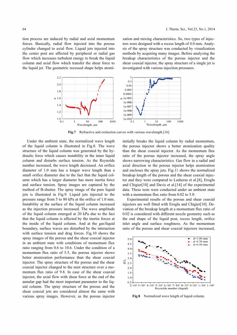
measured by a pressure transducer of WIKA S-10 which has an accuracy of 0.5 %, zero offset of 0.15 %, and hys-teresis of 0.15 %. A summary of the properties of water and ambient air is given in Table 1. The operating condi-tions of the liquid flow rate, air flow rate, momentum flux ratio and the geometric parameters of the two injec-tors are shown in Table 2. In the case of the porous in-jector, the pore size is 7.0 m, the thickness of the porous cylinder is 1.8 mm and the inner diameter is 3.5 mm. The shear coaxial injector has an inner diameter of 1.0 mm and an outer diameter of 3.5 mm. Detailed specifications of the porous injector and the shear coaxial injector are shown in Fig.6. The porous insert and injector is made of stainless steel material. Water and paint were injected with various injection conditions. In order to capture the spray structure and to measure the droplet sizes, a high speed camera and laser diffraction system were used. Visualization of the break-up process with the spray structure was obtained by a GIGAVIEWTM high speed CCD camera at a frame rate of 3,587 fps and an exposure time of 4 s. For each experiment, many images were captured and used to study the variation of wave devel-opment of the liquid column and the breakup of the spray jets. On average, 200 images were used for the analyzing structure in order to reduce deviation of experimental uncertainty due to the unstable spray structure. Volume flow rates of the gas jets were measured by an orifice flow meter which was composed of a precision orifice and two pressure transmitters. The laser diffraction sys-tem was Non-instructive and the Mie scattering tech-nique can measure the droplet sizes below 0.1 μm for the spherical droplets. The spray jets from the porous and shear coaxial injector was located at 200 mm of the measuring section. An unbroken liquid core, a ligament and non-uniform spherical droplets, where laser diffrac-tion anemometry cannot measure droplet size exactly, cannot be detected to the determination of detailed spray jets. The laser diffraction system was manufactured by Sympatec (Helos/Vario-KF) with a 5 mW, 633 nm He- Ne laser with a 29 mm beam diameter. The receiver has 31 channel multi-element detector rings and three radial centering elements. The receiver was fitted with an R6 lens with a focal length of 1,000 mm, so that droplet sizes could be measured to 1,750 m. For a time resolved droplet size distribution measurement, the laser diffrac-tion instrument was set to sample the diffracted light signal at the maximum acquiring rate of 2,000 Hz. Measured data were considered with ISO-13320-1, which is the number of particles in the working laser beam where the optical concentration is below the value of 25%. Depending on the optical properties of the drop-lets, scattered light may be absorbed and diffracted. Droplet sizes were considered by the ratio of refractive value (n) of 1.332 and extinction value (k) of 1.468e-8, which are shown in Fig.7.
Table 1 Injection nozzle geometries used in experiments. Parameter Water Ambient air
Temperature (K) 293±2 295±5
Density (kg/m3) 998.0 1.21±0.05
Surface tension (N/m) 0.0727
Viscosity (cP) 0.9247 0.0182
Table 2 Operating conditions and geometric parameter of porous injector and shear coaxial injector.
Parameters Value
Liquid flow rate (g/s) 5.2
Air flow rate (l/min) 10~400
Liquid velocity (m/s) 2.5~10.3
Air velocity (m/s) 54~233
Momentum flux ratio 0.2~10.6
Reynolds number of liquid 1.5~10.0×10³
DL(mm) - Inner diameter of center post 1.0
Dp(mm) - outer diameter of center post 3.5
Dpr(mm) - Inner diameter of porous cylinder 3.5
tpr(mm) - Thickness of porous cylinder 1.8
Lpr(mm) - Overall length of porous cylinder 4.0
R(mm) - Recess length of center post 4.0
Pores size(m) 7.0
Fig.6 Schematics of porous and shear coaxial injector.
Results & Discussion
Spray images and droplet sizes have been studied by using a porous injector and a shear coaxial injector. With the porous injector, liquid core breakup and the atomiza-
64 J. Therm. Sci., Vol.23, No.1, 2014
tion process are induced by radial and axial momentum forces. Basically, radial flow injected into the porous cylinder changed to axial flow. Liquid jets injected into the center post are affected by peripheral or radial gas flow which increases turbulent energy to break the liquid column and axial flow which transfer the shear force to the liquid jet. The geometric recessed shape helps atomi-
zation and mixing characteristics. So, two types of injec-tors were designed with a recess length of 4.0 mm. Analy-sis of the spray structure was conducted by visualization methods by acquiring many images. Before analyzing the breakup characteristics of the porous injector and the shear coaxial injector, the spray structure of a single jet is investigated with various injection pressures.
Fig.7 Refractive and extinction curves with various wavelength.[16]
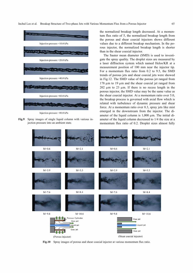
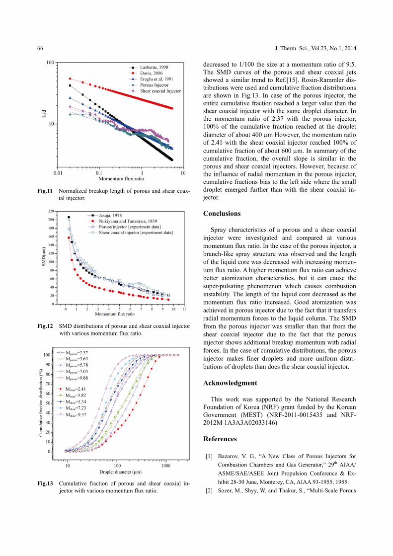
Under the ambient state, the normalized wave length of the liquid column is illustrated in Fig.8. The wave structure of the liquid column was generated by the hy-draulic force which causes instability in the inner liquid column and disturbs surface tension. As the Reynolds number increased, the wave length decreased. An orifice diameter of 1.0 mm has a longer wave length than a small orifice diameter due to the fact that the liquid col-umn which has a larger diameter has more inertia force and surface tension. Spray images are captured by the method of B-shutter. The spray image of the pure liquid jets is illustrated in Fig.9. Liquid jets injected to the pressure range from 5 to 80 kPa at the orifice of 1.0 mm. Instability at the surface of the liquid column increased as the injection pressure increased. The wave amplitude of the liquid column emerged at 20 kPa due to the fact that the liquid column is affected by the inertia forces at the inside of the liquid column. And at the gas/liquid boundary, surface waves are disturbed by the interaction with surface tension and drag forces. Fig.10 shows the spray images of the porous and the shear coaxial injector in an ambient state with conditions of momentum flux ratio ranging from 0.6 to 10.6. Under the condition of a momentum flux ratio of 5.5, the porous injector shows better atomization performance than the shear coaxial injector. The spray structure of the porous and the shear coaxial injector changed to the mist structure over a mo-mentum flux ratio of 9.8. In case of the shear coaxial injector, the axial flow with shear force at the end of the annular gap had the most important parameter to the liq-uid column. The spray structure of the porous and the shear coaxial jets are considered almost the same with various spray images. However, as the porous injector
initially breaks the liquid column by radial momentum, the porous injector shows a better atomization quality than the shear coaxial injector. As the momentum flux ratio of the porous injector increased, the spray angle shows narrowing characteristics. Gas flow in a radial and axial direction in the porous injector helps atomization and encloses the spray jets. Fig.11 shows the normalized breakup length of the porous and the shear coaxial injec-tor and they were compared to Lasheras et al.[8], Eroglu and Chigier[10] and Davis et al.[14] of the experimental data. These tests were conducted under an ambient state with a momentum flux ratio from 0.02 to 5.0.
Experimental results of the porous and shear coaxial injectors are well fitted with Eroglu and Chigier[10]. De-viation of the breakup length at a momentum flux ratio of 0.02 is considered with different nozzle geometry such as the end shape of the liquid post, recess length, orifice inlet angle and surface roughness. As the momentum ratio of the porous and shear coaxial injectors increased,
Fig.8 Normalized wave length of liquid column.
Inchul Lee et al. Breakup Structure of Two-phase Jets with Various Momentum Flux from a Porous Injector 65
Fig.9 Spray images of single liquid column with various in-jection pressure into an ambient state.
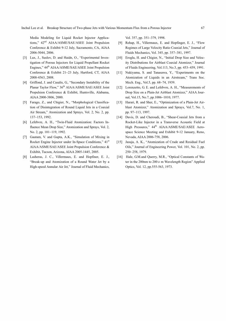
the normalized breakup length decreased. At a momen-tum flux ratio of 5, the normalized breakup length from the porous and shear coaxial injectors shows different values due to a different breakup mechanism. In the po-rous injector, the normalized breakup length is shorter than in the shear coaxial injector.
The Sauter mean diameter (SMD) is used to investi-gate the spray quality. The droplet sizes are measured by a laser diffraction system which named Helos/KR at a measurement position of 100 mm near the injector tip. For a momentum flux ratio from 0.2 to 9.5, the SMD trends of porous jets and shear coaxial jets were showed in Fig.12. The SMD value of the porous jet ranged from 178 m to 19 m and the shear coaxial jet ranged from 202 m to 23 m. If there is no recess length in the porous injector, the SMD value may be the same value as the shear coaxial injector. At a momentum ratio over 5.0, the breakup process is governed with axial flow which is related with turbulence of dynamic pressure and shear force. At a momentum ratio over 8.3, spray jets like mist emerged in the downstream from the injector. The di-ameter of the liquid column is 1,000 m. The initial di-ameter of the liquid column decreased to 1/4 the size at a momentum flux ratio of 0.2. Droplet sizes almost fully
Fig.10 Spray images of porous and shear coaxial injector at various momentum flux ratio.
66 J. Therm. Sci., Vol.23, No.1, 2014
Fig.11 Normalized breakup length of porous and shear coax-ial injector.
Fig.12 SMD distributions of porous and shear coaxial injector with various momentum flux ratio.
Fig.13 Cumulative fraction of porous and shear coaxial in-jector with various momentum flux ratio.
decreased to 1/100 the size at a momentum ratio of 9.5. The SMD curves of the porous and shear coaxial jets showed a similar trend to Ref.[15]. Rosin-Rammler dis-tributions were used and cumulative fraction distributions are shown in Fig.13. In case of the porous injector, the entire cumulative fraction reached a larger value than the shear coaxial injector with the same droplet diameter. In the momentum ratio of 2.37 with the porous injector, 100% of the cumulative fraction reached at the droplet diameter of about 400 m However, the momentum ratio of 2.41 with the shear coaxial injector reached 100% of cumulative fraction of about 600 m. In summary of the cumulative fraction, the overall slope is similar in the porous and shear coaxial injectors. However, because of the influence of radial momentum in the porous injector, cumulative fractions bias to the left side where the small droplet emerged further than with the shear coaxial in-jector.
Conclusions
Spray characteristics of a porous and a shear coaxial injector were investigated and compared at various momentum flux ratio. In the case of the porous injector, a branch-like spray structure was observed and the length of the liquid core was decreased with increasing momen-tum flux ratio. A higher momentum flux ratio can achieve better atomization characteristics, but it can cause the super-pulsating phenomenon which causes combustion instability. The length of the liquid core decreased as the momentum flux ratio increased. Good atomization was achieved in porous injector due to the fact that it transfers radial momentum forces to the liquid column. The SMD from the porous injector was smaller than that from the shear coaxial injector due to the fact that the porous injector shows additional breakup momentum with radial forces. In the case of cumulative distributions, the porous injector makes finer droplets and more uniform distri-butions of droplets than does the shear coaxial injector.
Acknowledgment
This work was supported by the National Research Foundation of Korea (NRF) grant funded by the Korean Government (MEST) (NRF-2011-0015435 and NRF- 2012M 1A3A3A02033146)
References
[1] Bazarov, V. G., “A New Class of Porous Injectors for
Combustion Chambers and Gas Generator,” 29th AIAA/
ASME/SAE/ASEE Joint Propulsion Conference & Ex-
hibit 28-30 June, Monterey, CA, AIAA 93-1955, 1955.
[2] Sozer, M., Shyy, W. and Thakur, S., “Multi-Scale Porous
Inchul Lee et al. Breakup Structure of Two-phase Jets with Various Momentum Flux from a Porous Injector 67
Media Modeling for Liquid Rocket Injector Applica-
tions,” 42nd AIAA/ASME/SAE/ASEE Joint Propulsion
Conference & Exhibit 9-12 July, Sacramento, CA, AIAA
2006-5044, 2006.
[3] Lux, J., Suslov, D. and Haidn, O., “Experimental Inves-
tigation of Porous Injectors for Liquid Propellant Rocket
Engines,” 44th AIAA/ASME/SAE/ASEE Joint Propulsion
Conference & Exhibit 2123 July, Hartford, CT, AIAA
2008-4563, 2008.
[4] Griffond, J. and Casalis, G., “Secondary Instability of the
Planar Taylor Flow,” 36th AIAA/ASME/SAE/ASEE Joint
Propulsion Conference & Exhibit, Huntsville, Alabama,
AIAA 2000-3806, 2000.
[5] Farago, Z., and Chigier, N., “Morphological Classifica-
tion of Disintegration of Round Liquid Jets in a Coaxial
Air Stream,” Atomization and Sprays, Vol. 2, No. 2, pp.
137153, 1992.
[6] Lefebvre, A. H., “Twin-Fluid Atomization: Factors In-
fluence Mean Drop Size,” Atomization and Sprays, Vol. 2,
No. 2, pp. 101119, 1992.
[7] Gautam, V. and Gupta, A.K., “Simulation of Mixing in
Rocket Engine Injector under In-Space Conditions,” 41st
AIAA/ASME/SAE/ASEE Joint Propulsion Conference &
Exhibit, Tucson, Arizona, AIAA 2005-1445, 2005.
[8] Lasheras, J. C., Villermaux, E. and Hopfiner, E. J.,
“Break-up and Atomization of a Round Water Jet by a
High-speed Annular Air Jet,” Journal of Fluid Mechanics,
Vol. 357, pp. 351379, 1998.
[9] Rehap, H., Villermaux, E. and Hopfinger, E. J., “Flow
Regimes of Large Velocity Ratio Coaxial Jets,” Journal of
Fluids Mechanics, Vol. 345, pp. 357381, 1997.
[10] Eroglu, H. and Chigier, N., “Initial Drop Size and Veloc-
ity Distributions for Airblast Coaxial Atomizer,” Journal
of Fluids Engineering, Vol.113, No.3, pp. 453459, 1991.
[11] Nukiyama, S. and Tanasawa, Y., “Experiments on the
Atomization of Liquids in an Airstream,” Trans Soc.
Mech. Eng., Vol.5, pp. 6874, 1939.
[12] Lorenzetto, G. E. and Lefebvre, A. H., “Measurements of
Drop Size on a Plain-Jet Airblast Atomizer,” AIAA Jour-
nal, Vol.15, No.7, pp.10061010, 1977.
[13] Harari, R. and Sher, E., “Optimization of a Plain-Jet Air-
blast Atomizer,” Atomization and Sprays, Vol.7, No. 1,
pp. 97113, 1997.
[14] Davis, D. and Cheroudi, B., “Shear-Coaxial Jets from a
Rocket-Like Injector in a Transverse Acoustic Field at
High Pressures,” 44th AIAA/ASME/SAE/ASEE Aero-
space Science Meeting and Exhibit 9-12 January, Reno,
Nevada, AIAA 2006-758, 2006.
[15] Jasuja, A. K., “Atomization of Crude and Residual Fuel
Oils,” Journal of Engineering Power, Vol. 101, No. 2, pp.
250258, 1979.
[16] Hale, G.M.and Querry, M.R., “Optical Constants of Wa-
ter in the 200nm to 200μm Wavelength Region” Applied
Optics, Vol. 12, pp.555-563, 1973.