Embed Size (px)
Citation preview

Appendix B
Ballast Cut-sheets

Revised 10/28/2005
Data is based upon tests performed by Advance Transformer in a controlled environment and representative of relative performance. Actual performance can vary depending on operating conditions. Specifications are subject to change without notice. All specifications are nominal unless otherwise noted.
ADVANCE TRANSFORMER CO.O'HARE INTERNATIONAL CENTER · 10275 WEST HIGGINS ROAD · ROSEMONT, IL 60018
Customer Support/Technical Service: Phone: 800-372-3331 · Fax: 630-307-3071Corporate Offices: Phone: 800-322-2086
VEZ-2S32-SCBrand Name MARK X POWERLINEBallast Type Electronic Dimming
Starting Method Programmed StartLamp Connection Series
Input Voltage 277Input Frequency 50/60 HZ
Status Active
Electrical Specifications
Lamp Type Num.of
Lamps
RatedLampWatts
Min.StartTemp(°F/C)
InputCurrent(Amps)
Input Power(Watts)
(min/max)
Ballast Factor(min/max)
MAXTHD%
PowerFactor
LampCurrent
Crest Factor
B.E.F.
F17T8 2 17 50/10 0.14 13/38 0.05/1.05 10 0.99 1.6 2.76 F25T8 2 25 50/10 0.20 13/55 0.05/1.05 10 0.99 1.6 1.91* F32T8 2 32 50/10 0.25 15/68 0.05/1.00 10 0.99 1.6 1.47
Wiring Diagram
BALLASTDIMMER
BLACKWHITE
RED
BLUEYELLOW
LINE
LAMP
LAMP
The wiring diagram that appears above is for the lamp type denoted by the asterisk (*)
Standard Lead Length (inches)
Enclosure
Enclosure Dimensions OverAll (L) Width (W) Height (H) Mounting (M)
9.50 " 1.7 " 1.18 " 8.90 "9 1/2 1 7/10 1 9/50 8 9/10
24.1 cm 4.3 cm 3 cm 22.6 cm
Advance # BAL1
Brian Smith UCSD Cal IT2 - Ballasts # of #
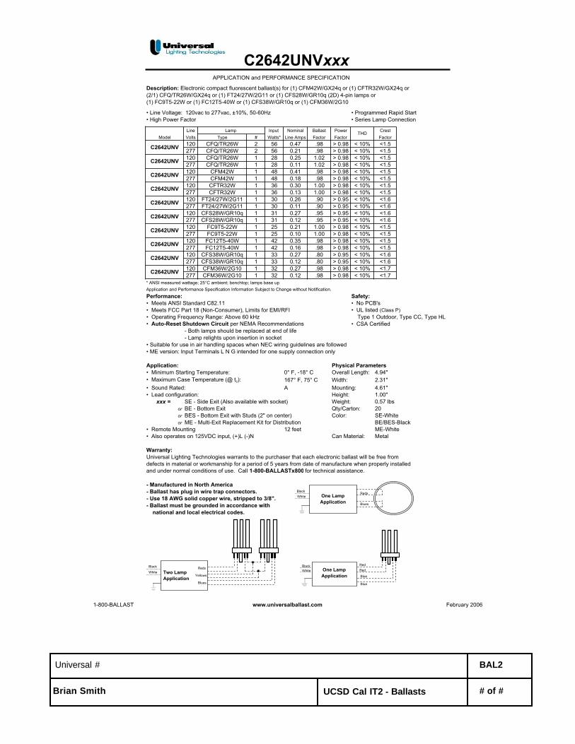
Description: Electronic compact fluorescent ballast(s) for (1) CFM42W/GX24q or (1) CFTR32W/GX24q or (2/1) CFQ/TR26W/GX24q or (1) FT24/27W/2G11 or (1) CFS28W/GR10q (2D) 4-pin lamps or(1) FC9T5-22W or (1) FC12T5-40W or (1) CFS38W/GR10q or (1) CFM36W/2G10
• Line Voltage: 120vac to 277vac, ±10%, 50-60Hz • Programmed Rapid Start• High Power Factor • Series Lamp Connection
Line Input Nominal Ballast Power CrestModel Volts Type # Watts* Line Amps Factor Factor Factor
120 CFQ/TR26W 2 56 0.47 .98 > 0.98 < 10% <1.5277 CFQ/TR26W 2 56 0.21 .98 > 0.98 < 10% <1.5120 CFQ/TR26W 1 28 0.25 1.02 > 0.98 < 10% <1.5277 CFQ/TR26W 1 28 0.11 1.02 > 0.98 < 10% <1.5120 CFM42W 1 48 0.41 .98 > 0.98 < 10% <1.5277 CFM42W 1 48 0.18 .98 > 0.98 < 10% <1.5120 CFTR32W 1 36 0.30 1.00 > 0.98 < 10% <1.5277 CFTR32W 1 36 0.13 1.00 > 0.98 < 10% <1.5120 FT24/27W/2G11 1 30 0.26 .90 > 0.95 < 10% <1.6277 FT24/27W/2G11 1 30 0.11 .90 > 0.95 < 10% <1.6120 CFS28W/GR10q 1 31 0.27 .95 > 0.95 < 10% <1.6277 CFS28W/GR10q 1 31 0.12 .95 > 0.95 < 10% <1.6120 FC9T5-22W 1 25 0.21 1.00 > 0.98 < 10% <1.5277 FC9T5-22W 1 25 0.10 1.00 > 0.98 < 10% <1.5120 FC12T5-40W 1 42 0.35 .98 > 0.98 < 10% <1.5277 FC12T5-40W 1 42 0.16 .98 > 0.98 < 10% <1.5120 CFS38W/GR10q 1 33 0.27 .80 > 0.95 < 10% <1.6277 CFS38W/GR10q 1 33 0.12 .80 > 0.95 < 10% <1.6120 CFM36W/2G10 1 32 0.27 .98 > 0.98 < 10% <1.7277 CFM36W/2G10 1 32 0.12 .98 > 0.98 < 10% <1.7
* ANSI measured wattage; 25°C ambient; benchtop; lamps base upApplication and Performance Specification Information Subject to Change without Notification.Performance: Safety:• Meets ANSI Standard C82.11 • No PCB's• Meets FCC Part 18 (Non-Consumer), Limits for EMI/RFI • UL listed (Class P)• Operating Frequency Range: Above 60 kHz Type 1 Outdoor, Type CC, Type HL• Auto-Reset Shutdown Circuit per NEMA Recommendations • CSA Certified
- Both lamps should be replaced at end of life- Lamp relights upon insertion in socket
• Suitable for use in air handling spaces when NEC wiring guidelines are followed• ME version: Input Terminals L N G intended for one supply connection only
Application: Physical Parameters• Minimum Starting Temperature: 0° F, -18° C Overall Length: 4.94"• Maximum Case Temperature (@ tc): 167° F, 75° C Width: 2.31"• Sound Rated: A Mounting: 4.61"• Lead configuration: Height: 1.00"
xxx = SE - Side Exit (Also available with socket) Weight: 0.57 lbsor BE - Bottom Exit Qty/Carton: 20or BES - Bottom Exit with Studs (2" on center) Color: SE-Whiteor ME - Multi-Exit Replacement Kit for Distribution BE/BES-Black
• Remote Mounting 12 feet ME-White• Also operates on 125VDC input, (+)L (-)N Can Material: Metal
Warranty:Universal Lighting Technologies warrants to the purchaser that each electronic ballast will be free fromdefects in material or workmanship for a period of 5 years from date of manufacture when properly installedand under normal conditions of use. Call 1-800-BALLASTx800 for technical assistance.
- Manufactured in North America- Ballast has plug in wire trap connectors.- Use 18 AWG solid copper wire, stripped to 3/8".- Ballast must be grounded in accordance with national and local electrical codes.
C2642UNVxxxAPPLICATION and PERFORMANCE SPECIFICATION
Lamp THD
C2642UNV
C2642UNV
C2642UNV
C2642UNV
C2642UNV
C2642UNV
C2642UNV
C2642UNV
C2642UNV
C2642UNV
BlackWhite One Lamp
Application
Reds
Blues
Black
WhiteReds
Yellows
Blues
Two LampApplication
BlackWhite One Lamp
Application
Red
Blue
Red
Blue
1-800-BALLAST www.universalballast.com February 2006
Universal # BAL2
Brian Smith UCSD Cal IT2 - Ballasts # of #

Revised 07/01/1999
Data is based upon tests performed by Advance Transformer in a controlled environment and representative of relative performance. Actual performance can vary depending on operating conditions. Specifications are subject to change without notice. All specifications are nominal unless otherwise noted.
ADVANCE TRANSFORMER CO.O'HARE INTERNATIONAL CENTER · 10275 WEST HIGGINS ROAD · ROSEMONT, IL 60018
Customer Support/Technical Service: Phone: 800-372-3331 · Fax: 630-307-3071Corporate Offices: Phone: 800-322-2086
VL-1B13-TP-BLSBrand Name COMPACT-NPFBallast Type Magnetic
Starting Method Pre-HeatLamp Connection Series
Input Voltage 277Input Frequency 60 HZ
Status Active
Electrical Specifications
Lamp Type Num.of
Lamps
RatedLamp Watts
Min. StartTemp (°F/C)
InputCurrent(Amps)
StartingCurrent(Amps)
OpenCircuit(Amps)
InputPower(Watts)
BallastFactor
MAXTHD%
PowerFactor
CFQ13W/GX23 1 13 0/-18 0.24 0.28 0.00 24 0.98 10 0.36* CFT13W/GX23 1 13 0/-18 0.26 0.28 0.00 20 0.98 15 0.28
Wiring Diagram
BALLAST
Diag. 45
LINE CAPOPTIONAL
BLK/WHT
WHITE
BLUE
The wiring diagram that appears above is for the lamp type denoted by the asterisk (*)
Standard Lead Length (inches)in. cm.
Black 0White 0Blue 7 17.8Red 0
Yellow 0Gray 0Violet 0
in. cm.Yellow/Blue 0
Blue/White 0Brown 0Orange 0
Orange/Black 0Black/White 7 17.8
Red/White 0
Enclosure
H
W ML
CASE "R"
Enclosure Dimensions OverAll (L) Width (std)/(TP) Height (H) Mounting (M)
4.75 " 2.21875 "/0 " 1.625 " 4.375 "4 3/4 2 7/32 / 0 1 5/8 4 3/8
12.1 cm 5.6 cm / 0 cm 4.1 cm 11.1 cm
Advance # BAL3
Brian Smith UCSD Cal IT2 - Ballasts # of #
R
Job Name:
Job Number:
Model Numbers:
PageSPECIF ICATION SUBMITTAL
Hi-lume (1) 07.08.04
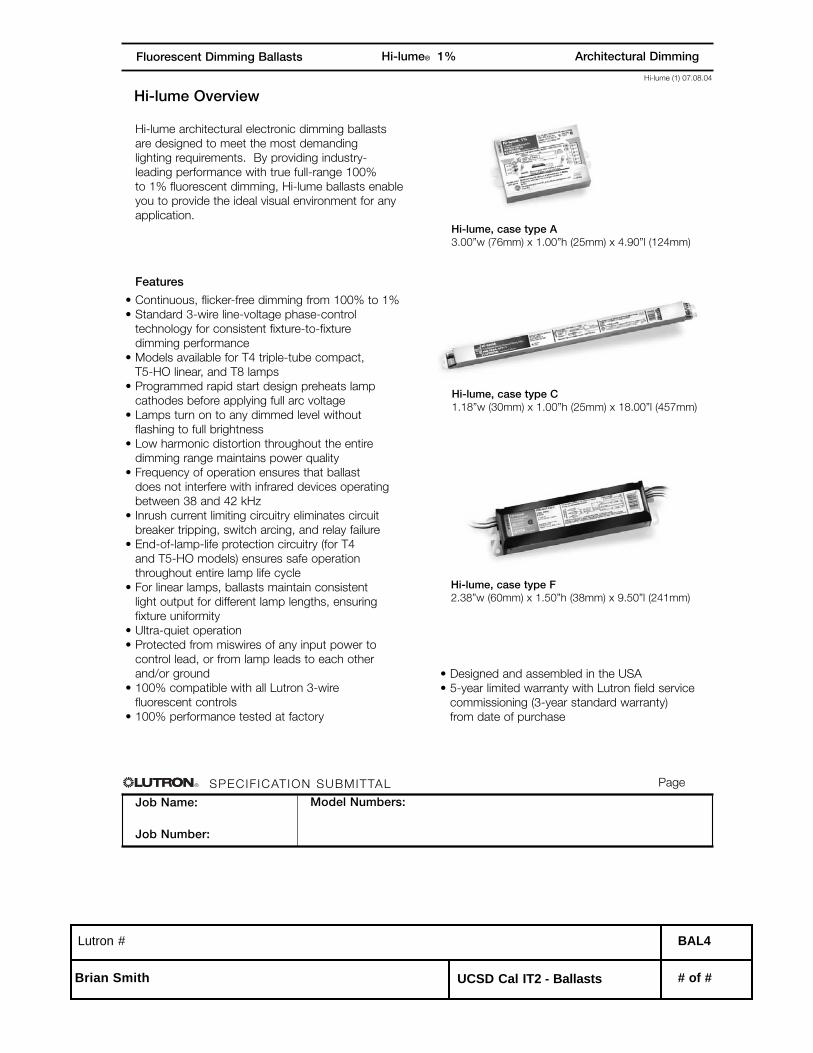
Architectural DimmingHi-lume® 1%Fluorescent Dimming Ballasts
Hi-lume Overview
Hi-lume architectural electronic dimming ballasts
are designed to meet the most demanding
lighting requirements. By providing industry-
leading performance with true full-range 100%
to 1% fluorescent dimming, Hi-lume ballasts enable
you to provide the ideal visual environment for any
application.
Features
• Continuous, flicker-free dimming from 100% to 1%
• Standard 3-wire line-voltage phase-control
technology for consistent fixture-to-fixture
dimming performance
• Models available for T4 triple-tube compact,
T5-HO linear, and T8 lamps
• Programmed rapid start design preheats lamp
cathodes before applying full arc voltage
• Lamps turn on to any dimmed level without
flashing to full brightness
• Low harmonic distortion throughout the entire
dimming range maintains power quality
• Frequency of operation ensures that ballast
does not interfere with infrared devices operating
between 38 and 42 kHz
• Inrush current limiting circuitry eliminates circuit
breaker tripping, switch arcing, and relay failure
• End-of-lamp-life protection circuitry (for T4
and T5-HO models) ensures safe operation
throughout entire lamp life cycle
• For linear lamps, ballasts maintain consistent
light output for different lamp lengths, ensuring
fixture uniformity
• Ultra-quiet operation
• Protected from miswires of any input power to
control lead, or from lamp leads to each other
and/or ground
• 100% compatible with all Lutron 3-wire
fluorescent controls
• 100% performance tested at factory
Hi-lume, case type A3.00”w (76mm) x 1.00”h (25mm) x 4.90”l (124mm)
Hi-lume, case type C1.18”w (30mm) x 1.00”h (25mm) x 18.00”l (457mm)
Hi-lume, case type F2.38”w (60mm) x 1.50”h (38mm) x 9.50”l (241mm)
• Designed and assembled in the USA
• 5-year limited warranty with Lutron field service
commissioning (3-year standard warranty)
from date of purchase
Lutron # BAL4
Brian Smith UCSD Cal IT2 - Ballasts # of #

R
Job Name:
Job Number:
Model Numbers:
PageSPECIF ICATION SUBMITTAL
Hi-lume (2) 07.08.04
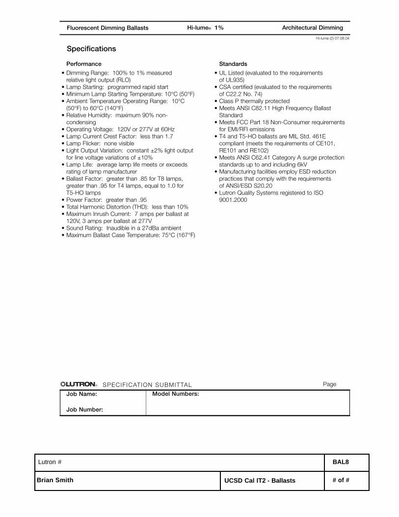
Architectural DimmingHi-lume® 1%Fluorescent Dimming Ballasts
Specifications
Performance
• Dimming Range: 100% to 1% measured
relative light output (RLO)
• Lamp Starting: programmed rapid start
• Minimum Lamp Starting Temperature: 10°C (50°F)
• Ambient Temperature Operating Range: 10°C
(50°F) to 60°C (140°F)
• Relative Humidity: maximum 90% non-
condensing
• Operating Voltage: 120V or 277V at 60Hz
• Lamp Current Crest Factor: less than 1.7
• Lamp Flicker: none visible
• Light Output Variation: constant ±2% light output
for line voltage variations of ±10%
• Lamp Life: average lamp life meets or exceeds
rating of lamp manufacturer
• Ballast Factor: greater than .85 for T8 lamps,
greater than .95 for T4 lamps, equal to 1.0 for
T5-HO lamps
• Power Factor: greater than .95
• Total Harmonic Distortion (THD): less than 10%
• Maximum Inrush Current: 7 amps per ballast at
120V, 3 amps per ballast at 277V
• Sound Rating: Inaudible in a 27dBa ambient
• Maximum Ballast Case Temperature: 75°C (167°F)
Standards
• UL Listed (evaluated to the requirements
of UL935)
• CSA certified (evaluated to the requirements
of C22.2 No. 74)
• Class P thermally protected
• Meets ANSI C82.11 High Frequency Ballast
Standard
• Meets FCC Part 18 Non-Consumer requirements
for EMI/RFI emissions
• T4 and T5-HO ballasts are MIL Std. 461E
compliant (meets the requirements of CE101,
RE101 and RE102)
• Meets ANSI C62.41 Category A surge protection
standards up to and including 6kV
• Manufacturing facilities employ ESD reduction
practices that comply with the requirements
of ANSI/ESD S20.20
• Lutron Quality Systems registered to ISO
9001.2000
Lutron # BAL4
Brian Smith UCSD Cal IT2 - Ballasts # of #

R
Job Name:
Job Number:
Model Numbers:
PageSPECIF ICATION SUBMITTAL
Hi-lume (3) 07.08.04
Architectural DimmingHi-lume® 1%Fluorescent Dimming Ballasts
Lamp
Type
120 VOLTS 277 VOLTSLamp
Watts
(length)
Lamps
per
ballast
Case
Type
Ballast
Current
(amps)
Hi-lumeModel Number 1
Ballast
Current
(amps)
Hi-lumeModel Number 1
T4 triple-tube4-pin
26W 1 A .26 HL3-T426-120-1-S .12 HL3-T426-277-1-S
32W 1 A .31 HL3-T432-120-1-S .13 HL3-T432-277-1-S
T5-HO linearhigh output
24W
(21.5”)
1
2
C
C
.26
.45
FDB-T524-120-1
FDB-T524-120-2
.13
.20
FDB-T524-277-1
FDB-T524-277-2
39W
(33.4”)
1
2
C
C
.38
.76
FDB-T539-120-1
FDB-T539-120-2
.17
.31
FDB-T539-277-1
FDB-T539-277-2
54W
(45.3”)
1
2
C
C
.58
1.1
FDB-T554-120-1
FDB-T554-120-2
.25
.45
FDB-T554-277-1
FDB-T554-277-2
T8 linear and U-bent
17W
(24”)
1
2
3
F
F
F
.19
.31
.43
FDB-2427-120-1
FDB-2427-120-2
FDB-2427-120-3
.08
.15
.20
FDB-2427-277-1
FDB-2427-277-2
FDB-2427-277-3
25W
(36”)
1
2
3
F
F
F
.24
.43
.62
FDB-3627-120-1
FDB-3627-120-2
FDB-3627-120-3
.12
.19
.28
FDB-3627-277-1
FDB-3627-277-2
FDB-3627-277-3
32W
(48”)
1
2
3
F
F
F
.30
.57
.82
FDB-4827-120-1
FDB-4827-120-2
FDB-4827-120-3
.14
.25
.35
FDB-4827-277-1
FDB-4827-277-2
FDB-4827-277-3
40W
(60”)
1
2
F
F
.36
.64
FDB-6027-120-1
FDB-6027-120-2
.16
.30
FDB-6027-277-1
FDB-6027-277-2
T12 linear HO(800ma)
85W
(72”)
1 F .75 FDB-7280-120-1 - - - -
95W
(84”)
1 F .83 FDB-8480-120-1 - - - -
110W
(96”)
1 F .88 FDB-9680-120-1 - - - -
1” diameter
1½” diameter
Hi-lume Ballast Models
1/2” diameter
5/8” diameter
1 Mounting studs standard for T4 ballasts. Delete suffix -S in the model number if mounting studs not needed.
Lutron # BAL4
Brian Smith UCSD Cal IT2 - Ballasts # of #
Revised 09/10/2002
Data is based upon tests performed by Advance Transformer in a controlled environment and representative of relative performance. Actual performance can vary depending on operating conditions. Specifications are subject to change without notice. All specifications are nominal unless otherwise noted.
ADVANCE TRANSFORMER CO.O'HARE INTERNATIONAL CENTER · 10275 WEST HIGGINS ROAD · ROSEMONT, IL 60018
Customer Support/Technical Service: Phone: 800-372-3331 · Fax: 630-307-3071Corporate Offices: Phone: 800-322-2086
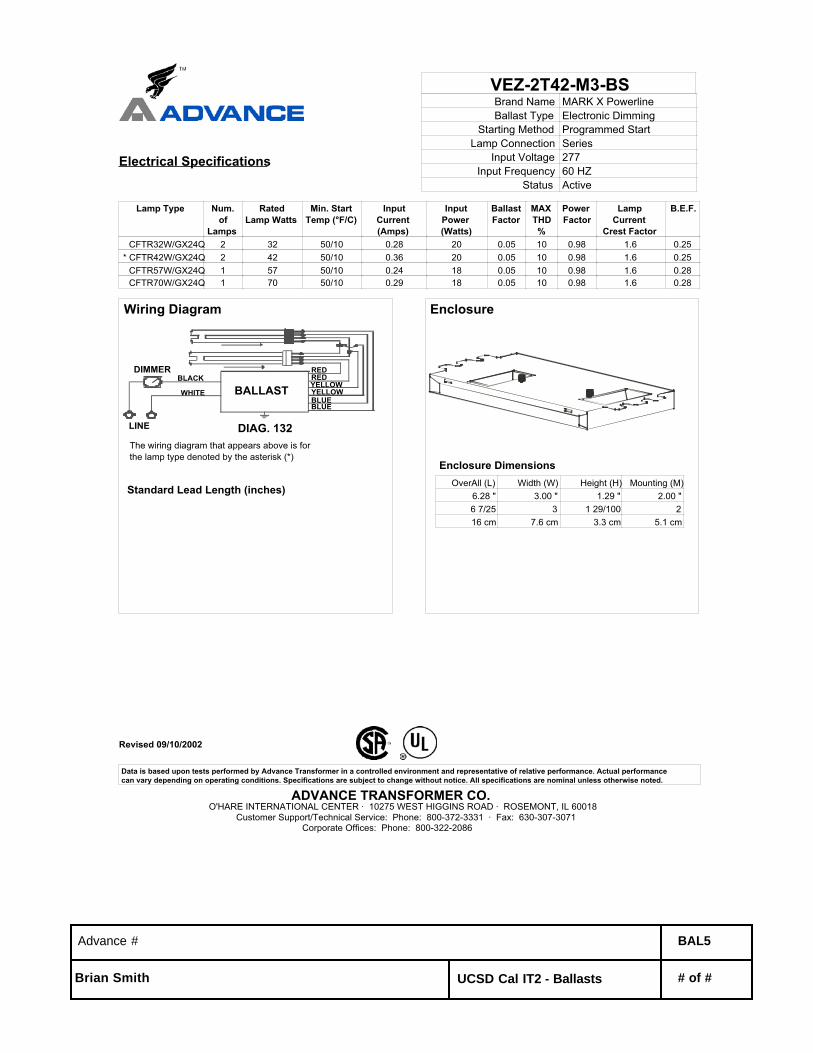
VEZ-2T42-M3-BSBrand Name MARK X PowerlineBallast Type Electronic Dimming
Starting Method Programmed StartLamp Connection Series
Input Voltage 277Input Frequency 60 HZ
Status Active
Electrical Specifications
Lamp Type Num.of
Lamps
RatedLamp Watts
Min. StartTemp (°F/C)
InputCurrent(Amps)
InputPower(Watts)
BallastFactor
MAXTHD%
PowerFactor
LampCurrent
Crest Factor
B.E.F.
CFTR32W/GX24Q 2 32 50/10 0.28 20 0.05 10 0.98 1.6 0.25* CFTR42W/GX24Q 2 42 50/10 0.36 20 0.05 10 0.98 1.6 0.25 CFTR57W/GX24Q 1 57 50/10 0.24 18 0.05 10 0.98 1.6 0.28 CFTR70W/GX24Q 1 70 50/10 0.29 18 0.05 10 0.98 1.6 0.28
Wiring Diagram
REDRED
BLUEBLUEYELLOWYELLOWBALLAST
DIAG. 132LINE
WHITE
BLACKDIMMER
The wiring diagram that appears above is for the lamp type denoted by the asterisk (*)
Standard Lead Length (inches)
Enclosure
Enclosure Dimensions OverAll (L) Width (W) Height (H) Mounting (M)
6.28 " 3.00 " 1.29 " 2.00 "6 7/25 3 1 29/100 216 cm 7.6 cm 3.3 cm 5.1 cm
Advance # BAL5
Brian Smith UCSD Cal IT2 - Ballasts # of #

Revised 10/28/2005
Data is based upon tests performed by Advance Transformer in a controlled environment and representative of relative performance. Actual performance can vary depending on operating conditions. Specifications are subject to change without notice. All specifications are nominal unless otherwise noted.
ADVANCE TRANSFORMER CO.O'HARE INTERNATIONAL CENTER · 10275 WEST HIGGINS ROAD · ROSEMONT, IL 60018
Customer Support/Technical Service: Phone: 800-372-3331 · Fax: 630-307-3071Corporate Offices: Phone: 800-322-2086
VEZ-132-SCBrand Name MARK X POWERLINEBallast Type Electronic Dimming
Starting Method Programmed StartLamp Connection Series
Input Voltage 277Input Frequency 50/60 HZ
Status Active
Electrical Specifications
Lamp Type Num.of
Lamps
RatedLampWatts
Min.StartTemp(°F/C)
InputCurrent(Amps)
Input Power(Watts)
(min/max)
Ballast Factor(min/max)
MAXTHD%
PowerFactor
LampCurrent
Crest Factor
B.E.F.
F17T8 1 17 50/10 0.09 07/24 0.05/1.05 10 0.99 1.6 4.38 F25T8 1 25 50/10 0.11 07/30 0.05/1.05 10 0.99 1.6 3.50* F32T8 1 32 50/10 0.13 09/35 0.05/1.00 10 0.99 1.6 2.86
Wiring Diagram
RED
BLUE
DIMMER
WHITE
BLACK/WHITE
LINE
BALLAST
The wiring diagram that appears above is for the lamp type denoted by the asterisk (*)
Standard Lead Length (inches)
Enclosure
Enclosure Dimensions OverAll (L) Width (W) Height (H) Mounting (M)
9.50 " 1.7 " 1.18 " 8.90 "9 1/2 1 7/10 1 9/50 8 9/10
24.1 cm 4.3 cm 3 cm 22.6 cm
Advance # BAL6
Brian Smith UCSD Cal IT2 - Ballasts # of #

Revised 12/03/2003
Data is based upon tests performed by Advance Transformer in a controlled environment and representative of relative performance. Actual performance can vary depending on operating conditions. Specifications are subject to change without notice. All specifications are nominal unless otherwise noted.
ADVANCE TRANSFORMER CO.O'HARE INTERNATIONAL CENTER · 10275 WEST HIGGINS ROAD · ROSEMONT, IL 60018
Customer Support/Technical Service: Phone: 800-372-3331 · Fax: 630-307-3071Corporate Offices: Phone: 800-322-2086
IDL-2S26-M5-BS@277Brand Name ROVRBallast Type Electronic Dimming
Starting Method Programmed StartLamp Connection Series
Input Voltage 120-277Input Frequency 50/60 HZ
Status Active
Electrical Specifications
Lamp Type Num.of
Lamps
RatedLampWatts
Min.StartTemp(°F/C)
InputCurrent(Amps)
Input Power(Watts)
(min/max)
Ballast Factor(min/max)
MAXTHD%
PowerFactor
LampCurrent
Crest Factor
B.E.F.
* CFQ13W/G24Q 1 13 50/10 0.07 06/18 0.03/1.00 10 0.99 1.6 5.56 CFQ13W/G24Q 2 13 50/10 0.12 09/32 0.03/1.00 10 0.99 1.6 3.13
Wiring Diagram
The wiring diagram that appears above is for the lamp type denoted by the asterisk (*)
Standard Lead Length (inches)in. cm.
Black 0 0White 0 0Blue 0 0Red 0 0
Yellow 0 0Gray 0Violet 0
in. cm.Yellow/Blue 0
Blue/White 0Brown 0Orange 0
Orange/Black 0Black/White 0
Red/White 0
Enclosure
Enclosure Dimensions OverAll (L) Width (W) Height (H) Mounting (M)
4.98 " 3.00 " 1.18 " 2.00 "4 49/50 3 1 9/50 212.6 cm 7.6 cm 3 cm 5.1 cm
Advance # BAL7
Brian Smith UCSD Cal IT2 - Ballasts # of #

R
Job Name:
Job Number:
Model Numbers:
PageSPECIF ICATION SUBMITTAL
Hi-lume (1) 07.08.04
Architectural DimmingHi-lume® 1%Fluorescent Dimming Ballasts
Hi-lume Overview
Hi-lume architectural electronic dimming ballasts
are designed to meet the most demanding
lighting requirements. By providing industry-
leading performance with true full-range 100%
to 1% fluorescent dimming, Hi-lume ballasts enable
you to provide the ideal visual environment for any
application.
Features
• Continuous, flicker-free dimming from 100% to 1%
• Standard 3-wire line-voltage phase-control
technology for consistent fixture-to-fixture
dimming performance
• Models available for T4 triple-tube compact,
T5-HO linear, and T8 lamps
• Programmed rapid start design preheats lamp
cathodes before applying full arc voltage
• Lamps turn on to any dimmed level without
flashing to full brightness
• Low harmonic distortion throughout the entire
dimming range maintains power quality
• Frequency of operation ensures that ballast
does not interfere with infrared devices operating
between 38 and 42 kHz
• Inrush current limiting circuitry eliminates circuit
breaker tripping, switch arcing, and relay failure
• End-of-lamp-life protection circuitry (for T4
and T5-HO models) ensures safe operation
throughout entire lamp life cycle
• For linear lamps, ballasts maintain consistent
light output for different lamp lengths, ensuring
fixture uniformity
• Ultra-quiet operation
• Protected from miswires of any input power to
control lead, or from lamp leads to each other
and/or ground
• 100% compatible with all Lutron 3-wire
fluorescent controls
• 100% performance tested at factory
Hi-lume, case type A3.00”w (76mm) x 1.00”h (25mm) x 4.90”l (124mm)
Hi-lume, case type C1.18”w (30mm) x 1.00”h (25mm) x 18.00”l (457mm)
Hi-lume, case type F2.38”w (60mm) x 1.50”h (38mm) x 9.50”l (241mm)
• Designed and assembled in the USA
• 5-year limited warranty with Lutron field service
commissioning (3-year standard warranty)
from date of purchase
Lutron # BAL8
Brian Smith UCSD Cal IT2 - Ballasts # of #
R
Job Name:
Job Number:
Model Numbers:
PageSPECIF ICATION SUBMITTAL
Hi-lume (2) 07.08.04
Architectural DimmingHi-lume® 1%Fluorescent Dimming Ballasts
Specifications
Performance
• Dimming Range: 100% to 1% measured
relative light output (RLO)
• Lamp Starting: programmed rapid start
• Minimum Lamp Starting Temperature: 10°C (50°F)
• Ambient Temperature Operating Range: 10°C
(50°F) to 60°C (140°F)
• Relative Humidity: maximum 90% non-
condensing
• Operating Voltage: 120V or 277V at 60Hz
• Lamp Current Crest Factor: less than 1.7
• Lamp Flicker: none visible
• Light Output Variation: constant ±2% light output
for line voltage variations of ±10%
• Lamp Life: average lamp life meets or exceeds
rating of lamp manufacturer
• Ballast Factor: greater than .85 for T8 lamps,
greater than .95 for T4 lamps, equal to 1.0 for
T5-HO lamps
• Power Factor: greater than .95
• Total Harmonic Distortion (THD): less than 10%
• Maximum Inrush Current: 7 amps per ballast at
120V, 3 amps per ballast at 277V
• Sound Rating: Inaudible in a 27dBa ambient
• Maximum Ballast Case Temperature: 75°C (167°F)
Standards
• UL Listed (evaluated to the requirements
of UL935)
• CSA certified (evaluated to the requirements
of C22.2 No. 74)
• Class P thermally protected
• Meets ANSI C82.11 High Frequency Ballast
Standard
• Meets FCC Part 18 Non-Consumer requirements
for EMI/RFI emissions
• T4 and T5-HO ballasts are MIL Std. 461E
compliant (meets the requirements of CE101,
RE101 and RE102)
• Meets ANSI C62.41 Category A surge protection
standards up to and including 6kV
• Manufacturing facilities employ ESD reduction
practices that comply with the requirements
of ANSI/ESD S20.20
• Lutron Quality Systems registered to ISO
9001.2000
Lutron # BAL8
Brian Smith UCSD Cal IT2 - Ballasts # of #

R
Job Name:
Job Number:
Model Numbers:
PageSPECIF ICATION SUBMITTAL
Hi-lume (3) 07.08.04
Architectural DimmingHi-lume® 1%Fluorescent Dimming Ballasts
Lamp
Type
120 VOLTS 277 VOLTSLamp
Watts
(length)
Lamps
per
ballast
Case
Type
Ballast
Current
(amps)
Hi-lumeModel Number 1
Ballast
Current
(amps)
Hi-lumeModel Number 1
T4 triple-tube4-pin
26W 1 A .26 HL3-T426-120-1-S .12 HL3-T426-277-1-S
32W 1 A .31 HL3-T432-120-1-S .13 HL3-T432-277-1-S
T5-HO linearhigh output
24W
(21.5”)
1
2
C
C
.26
.45
FDB-T524-120-1
FDB-T524-120-2
.13
.20
FDB-T524-277-1
FDB-T524-277-2
39W
(33.4”)
1
2
C
C
.38
.76
FDB-T539-120-1
FDB-T539-120-2
.17
.31
FDB-T539-277-1
FDB-T539-277-2
54W
(45.3”)
1
2
C
C
.58
1.1
FDB-T554-120-1
FDB-T554-120-2
.25
.45
FDB-T554-277-1
FDB-T554-277-2
T8 linear and U-bent
17W
(24”)
1
2
3
F
F
F
.19
.31
.43
FDB-2427-120-1
FDB-2427-120-2
FDB-2427-120-3
.08
.15
.20
FDB-2427-277-1
FDB-2427-277-2
FDB-2427-277-3
25W
(36”)
1
2
3
F
F
F
.24
.43
.62
FDB-3627-120-1
FDB-3627-120-2
FDB-3627-120-3
.12
.19
.28
FDB-3627-277-1
FDB-3627-277-2
FDB-3627-277-3
32W
(48”)
1
2
3
F
F
F
.30
.57
.82
FDB-4827-120-1
FDB-4827-120-2
FDB-4827-120-3
.14
.25
.35
FDB-4827-277-1
FDB-4827-277-2
FDB-4827-277-3
40W
(60”)
1
2
F
F
.36
.64
FDB-6027-120-1
FDB-6027-120-2
.16
.30
FDB-6027-277-1
FDB-6027-277-2
T12 linear HO(800ma)
85W
(72”)
1 F .75 FDB-7280-120-1 - - - -
95W
(84”)
1 F .83 FDB-8480-120-1 - - - -
110W
(96”)
1 F .88 FDB-9680-120-1 - - - -
1” diameter
1½” diameter
Hi-lume Ballast Models
1/2” diameter
5/8” diameter
1 Mounting studs standard for T4 ballasts. Delete suffix -S in the model number if mounting studs not needed.
Lutron # BAL8
Brian Smith UCSD Cal IT2 - Ballasts # of #

Revised 07/23/2004
Data is based upon tests performed by Advance Transformer in a controlled environment and representative of relative performance. Actual performance can vary depending on operating conditions. Specifications are subject to change without notice. All specifications are nominal unless otherwise noted.
ADVANCE TRANSFORMER CO.O'HARE INTERNATIONAL CENTER · 10275 WEST HIGGINS ROAD · ROSEMONT, IL 60018
Customer Support/Technical Service: Phone: 800-372-3331 · Fax: 630-307-3071Corporate Offices: Phone: 800-322-2086
VCN-2M32-MCBrand Name CENTIUM MICRO CANBallast Type Electronic
Starting Method Instant StartLamp Connection Series
Input Voltage 277Input Frequency 60 HZ
Status Active
Electrical Specifications
Lamp Type Num.of
Lamps
RatedLamp Watts
Min. StartTemp (°F/C)
InputCurrent(Amps)
InputPower
(ANSI Watts)
BallastFactor
MAXTHD%
PowerFactor
MAX LampCurrent
Crest Factor
B.E.F.
F21T5 2 21 50/10 0.18 50 1.10 10 0.98 1.7 2.20 F25T8 2 25 0/-18 0.18 49 0.88 10 0.99 1.7 1.80 F28T5 2 28 50/10 0.22 60 0.98 10 0.99 1.7 1.63* F32T8 2 32 0/-18 0.21 59 0.88 10 0.99 1.7 1.49
F32T8/ES (30W) 2 30 60/16 0.20 54 0.88 10 0.99 1.7 1.63
Wiring Diagram
BALLAST
Diag. 64
LAMP
WHITEBLACK
RED
BLUE
LINELAMP
BLUE
The wiring diagram that appears above is for the lamp type denoted by the asterisk (*)
Standard Lead Length (inches)in. cm.
Black 0White 25L 63.5Blue 31R 78.7Red 37L 94
Yellow 0Gray 0Violet 0
in. cm.Yellow/Blue 0
Blue/White 0Brown 0Orange 0
Orange/Black 0Black/White 25L 63.5
Red/White 0
Enclosure
Enclosure Dimensions OverAll (L) Width (W) Height (H) Mounting (M)
9.50 " 1.08 " 1.05 " 8.91 "9 1/2 1 2/25 1 1/20 8 91/100
24.1 cm 2.7 cm 2.7 cm 22.6 cm
Advance # BAL9
Brian Smith UCSD Cal IT2 - Ballasts # of #
Revised 07/23/2004
Data is based upon tests performed by Advance Transformer in a controlled environment and representative of relative performance. Actual performance can vary depending on operating conditions. Specifications are subject to change without notice. All specifications are nominal unless otherwise noted.
ADVANCE TRANSFORMER CO.O'HARE INTERNATIONAL CENTER · 10275 WEST HIGGINS ROAD · ROSEMONT, IL 60018
Customer Support/Technical Service: Phone: 800-372-3331 · Fax: 630-307-3071Corporate Offices: Phone: 800-322-2086
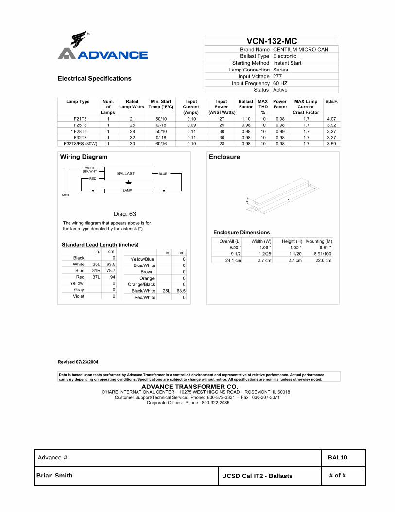
VCN-132-MCBrand Name CENTIUM MICRO CANBallast Type Electronic
Starting Method Instant StartLamp Connection Series
Input Voltage 277Input Frequency 60 HZ
Status Active
Electrical Specifications
Lamp Type Num.of
Lamps
RatedLamp Watts
Min. StartTemp (°F/C)
InputCurrent(Amps)
InputPower
(ANSI Watts)
BallastFactor
MAXTHD%
PowerFactor
MAX LampCurrent
Crest Factor
B.E.F.
F21T5 1 21 50/10 0.10 27 1.10 10 0.98 1.7 4.07 F25T8 1 25 0/-18 0.09 25 0.98 10 0.98 1.7 3.92* F28T5 1 28 50/10 0.11 30 0.98 10 0.99 1.7 3.27 F32T8 1 32 0/-18 0.11 30 0.98 10 0.98 1.7 3.27
F32T8/ES (30W) 1 30 60/16 0.10 28 0.98 10 0.98 1.7 3.50
Wiring Diagram
BALLAST
Diag. 63
LAMP
WHITE
REDBLUE
LINE
BLK/WHT
The wiring diagram that appears above is for the lamp type denoted by the asterisk (*)
Standard Lead Length (inches)in. cm.
Black 0White 25L 63.5Blue 31R 78.7Red 37L 94
Yellow 0Gray 0Violet 0
in. cm.Yellow/Blue 0
Blue/White 0Brown 0Orange 0
Orange/Black 0Black/White 25L 63.5
Red/White 0
Enclosure
Enclosure Dimensions OverAll (L) Width (W) Height (H) Mounting (M)
9.50 " 1.08 " 1.05 " 8.91 "9 1/2 1 2/25 1 1/20 8 91/100
24.1 cm 2.7 cm 2.7 cm 22.6 cm
Advance # BAL10
Brian Smith UCSD Cal IT2 - Ballasts # of #
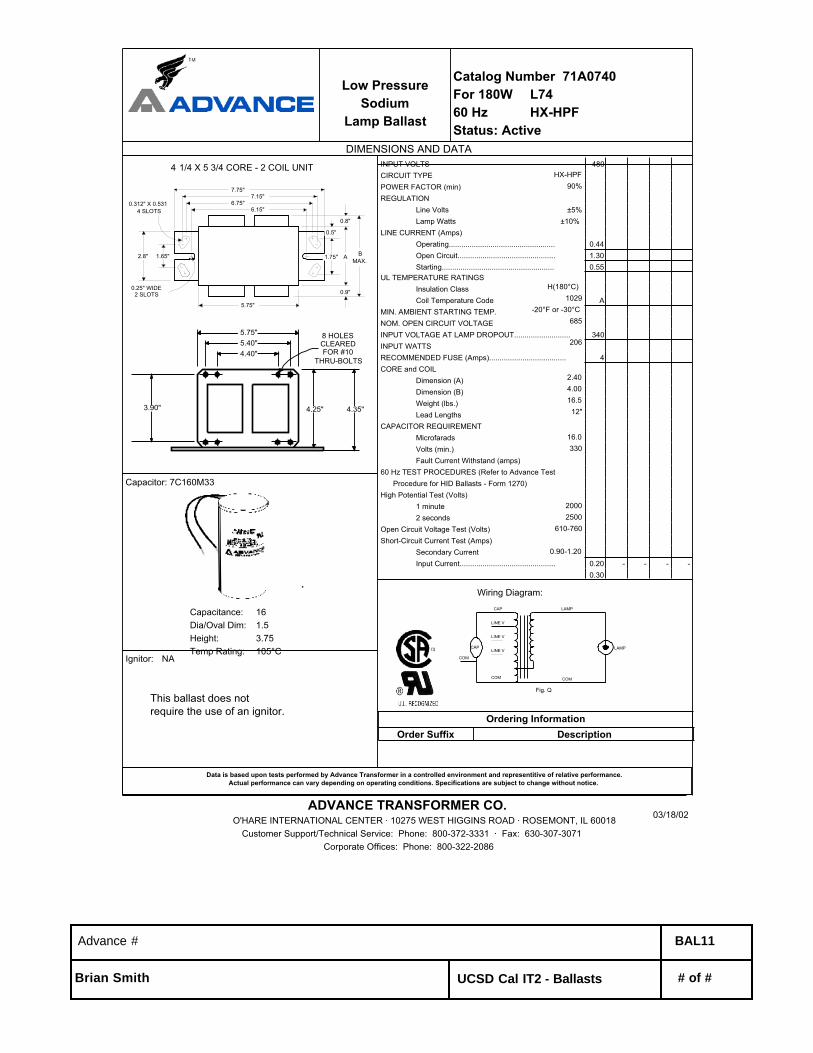
Low PressureSodium
Lamp Ballast
Catalog Number 71A0740For 180W L7460 Hz HX-HPFStatus: Active
DIMENSIONS AND DATA
1.65"
7.75"7.15"
BMAX.
0.8"
0.25" WIDE2 SLOTS
A
0.9"
1.75"
0.5"
2.8"
6.75"6.15"
0.312" X 0.5314 SLOTS
5.75"
4 1/4 X 5 3/4 CORE - 2 COIL UNIT
3.90"
5.75"5.40"
4.35"4.25"
8 HOLESCLEAREDFOR #10
THRU-BOLTS4.40"
Capacitor: 7C160M33
Capacitance: 16Dia/Oval Dim: 1.5Height: 3.75Temp Rating: 105°C
This ballast does notrequire the use of an ignitor.
Ignitor: NA
Data is based upon tests performed by Advance Transformer in a controlled environment and representitive of relative performance.Actual performance can vary depending on operating conditions. Specifications are subject to change without notice.
ADVANCE TRANSFORMER CO.O'HARE INTERNATIONAL CENTER · 10275 WEST HIGGINS ROAD · ROSEMONT, IL 60018
Customer Support/Technical Service: Phone: 800-372-3331 · Fax: 630-307-3071Corporate Offices: Phone: 800-322-2086
INPUT VOLTS 480CIRCUIT TYPEPOWER FACTOR (min)REGULATION Line Volts Lamp WattsLINE CURRENT (Amps) Operating................................................... 0.44 Open Circuit............................................... 1.30 Starting...................................................... 0.55UL TEMPERATURE RATINGS Insulation Class Coil Temperature Code AMIN. AMBIENT STARTING TEMP.NOM. OPEN CIRCUIT VOLTAGEINPUT VOLTAGE AT LAMP DROPOUT........................... 340INPUT WATTSRECOMMENDED FUSE (Amps)..................................... 4CORE and COIL Dimension (A) Dimension (B) Weight (lbs.) Lead LengthsCAPACITOR REQUIREMENT Microfarads Volts (min.) Fault Current Withstand (amps)60 Hz TEST PROCEDURES (Refer to Advance Test Procedure for HID Ballasts - Form 1270)High Potential Test (Volts) 1 minute 2 secondsOpen Circuit Voltage Test (Volts)Short-Circuit Current Test (Amps) Secondary Current Input Current.............................................. 0.20 - - - -
0.30
HX-HPF90%
±5%±10%
H(180°C)1029
-20°F or -30°C685
206
2.404.0016.5
12"
16.0330
20002500
610-760
0.90-1.20
Wiring Diagram:
Fig. Q
LAMP
CAP LAMP
COM COM
LINE V
LINE V
COM
LINE V
CAP
Ordering InformationOrder Suffix Description
03/18/02
Advance # BAL11
Brian Smith UCSD Cal IT2 - Ballasts # of #

e-Vision ElectronicBallast for Metal Halide Lamps
Catalog Number IMH-50-A For (1) 39W ANSI M130 or(1) 50W ANSI M110 Metal Halide Lamp120-277V 50/60Hz Electronic Status: Active
DIMENSIONS AND DATALamp Data
Number WattsInputVolts
CatalogNumber*
LineCurrent(Amps)
InputPower
(W)
BallastFactor
MaxTHD(%)
MinPowerFactor
WiringDia Figure Weight
(lb)
MaxDistanceto Lamp
(ft)
39 Watt Lamp, ANSI Code M130 Minimum Starting Temp -30°C/-20°F120 0.38 45
1 39277
IMH-50-A-xxx0.16 44
1.0 15 0.9 1 A 1.4 5
50 Watt Lamp, ANSI Code M110 Minimum Starting Temp -30°C/-20°F
120 0.47 561 50
277IMH-50-A-xxx
0.20 551.0 15 0.9 2 A 1.4 5
*Ordering Information Order Suffix Description
-LF Ballast with side exit leads and mounting feet
INSTALLATION & APPLICATION NOTES:1. Maximum allowable case temperature is 85°C. See figure above
for measurement location 2. Ignition pulse is 4 kV max3. All leads are 12 inches long4. Ballast output will shutdown after 20 minutes if lamp fails to ignite5. Power must be cycled off – then on, after replacing lamp
-BLS Ballast with bottom exit leads and mountingstuds
Data is based on tests performed by Advance transformer in a controlled environment and representative of relative performance. Actual performance can vary depending on operating conditions.Specifications are subject to change without notice. All specifications are nominal unless otherwise noted.
Advance • 10275 West Higgins Road • Rosemont, Illinois 60018-5603 • (847) 390-5000 • fax: 847-390-5109 • www.advancetransformer.com
A DIVISION OF PHILIPS ELECTRONICS NORTH AMERICA CORPORATION
Wiring Diagram 1
Figure A
CASE LENGTH = 4.72" [120mm]MOUNTING LENGTH = 5.20" [132mm]MOUNTING WIDTH = 2.87" [73mm]OVERALL LENGTH = 5.51" [140mm]CASE WIDTH = 3.62" [92mm]HEIGHT = 1.50" [38mm]
Wiring Diagram 2
Case Temperature Measurement Location
MEASURE CASETEMPERATURE ONRIGHT HEAT SINKCLIP AT BALASTEND
10/11//05
Advance # BAL12
Brian Smith UCSD Cal IT2 - Ballasts # of #

Revised 09/14/1999
Data is based upon tests performed by Advance Transformer in a controlled environment and representative of relative performance. Actual performance can vary depending on operating conditions. Specifications are subject to change without notice. All specifications are nominal unless otherwise noted.
ADVANCE TRANSFORMER CO.O'HARE INTERNATIONAL CENTER · 10275 WEST HIGGINS ROAD · ROSEMONT, IL 60018
Customer Support/Technical Service: Phone: 800-372-3331 · Fax: 630-307-3071Corporate Offices: Phone: 800-322-2086
VL-1B9-TP-BLSBrand Name COMPACT-NPFBallast Type Magnetic
Starting Method Pre-HeatLamp Connection Series
Input Voltage 277Input Frequency 60 HZ
Status Active
Electrical Specifications
Lamp Type Num.of
Lamps
RatedLamp Watts
Min. StartTemp (°F/C)
InputCurrent(Amps)
StartingCurrent(Amps)
OpenCircuit(Amps)
InputPower(Watts)
BallastFactor
MAXTHD%
PowerFactor
CFQ9W/G23 1 9 0/-18 0.16 0.18 0.00 15 0.90 10 0.33 CFT5W/G23 1 5 0/-18 0.17 0.18 0.00 12 0.96 15 0.25 CFT7W/G23 1 7 0/-18 0.17 0.18 0.00 14 0.95 15 0.29* CFT9W/G23 1 9 0/-18 0.17 0.18 0.00 14 0.92 15 0.31
Wiring Diagram
BALLAST
Diag. 42
LINE LAMPCAPOPTIONAL
BLK/WHT
WHITE
BLUE
The wiring diagram that appears above is for the lamp type denoted by the asterisk (*)
Standard Lead Length (inches)in. cm.
Black 0White 0Blue 7 17.8Red 0
Yellow 0Gray 0Violet 0
in. cm.Yellow/Blue 0
Blue/White 0Brown 0Orange 0
Orange/Black 0Black/White 7 17.8
Red/White 0
Enclosure
H
W ML
CASE "R"
Enclosure Dimensions OverAll (L) Width (std)/(TP) Height (H) Mounting (M)
4.75 " 2.21875 "/0 " 1.625 " 4.375 "4 3/4 2 7/32 / 0 1 5/8 4 3/8
12.1 cm 5.6 cm / 0 cm 4.1 cm 11.1 cm
Advance # BAL13
Brian Smith UCSD Cal IT2 - Ballasts # of #

Revised 07/01/1999
Data is based upon tests performed by Advance Transformer in a controlled environment and representative of relative performance. Actual performance can vary depending on operating conditions. Specifications are subject to change without notice. All specifications are nominal unless otherwise noted.
ADVANCE TRANSFORMER CO.O'HARE INTERNATIONAL CENTER · 10275 WEST HIGGINS ROAD · ROSEMONT, IL 60018
Customer Support/Technical Service: Phone: 800-372-3331 · Fax: 630-307-3071Corporate Offices: Phone: 800-322-2086
VL-1B13-TP-BLSBrand Name COMPACT-NPFBallast Type Magnetic
Starting Method Pre-HeatLamp Connection Series
Input Voltage 277Input Frequency 60 HZ
Status Active
Electrical Specifications
Lamp Type Num.of
Lamps
RatedLamp Watts
Min. StartTemp (°F/C)
InputCurrent(Amps)
StartingCurrent(Amps)
OpenCircuit(Amps)
InputPower(Watts)
BallastFactor
MAXTHD%
PowerFactor
* CFQ13W/GX23 1 13 0/-18 0.24 0.28 0.00 24 0.98 10 0.36 CFT13W/GX23 1 13 0/-18 0.26 0.28 0.00 20 0.98 15 0.28
Wiring Diagram
BALLAST
Diag. 45
LINE CAPOPTIONAL
BLK/WHT
WHITE
BLUE
The wiring diagram that appears above is for the lamp type denoted by the asterisk (*)
Standard Lead Length (inches)in. cm.
Black 0White 0Blue 7 17.8Red 0
Yellow 0Gray 0Violet 0
in. cm.Yellow/Blue 0
Blue/White 0Brown 0Orange 0
Orange/Black 0Black/White 7 17.8
Red/White 0
Enclosure
H
W ML
CASE "R"
Enclosure Dimensions OverAll (L) Width (std)/(TP) Height (H) Mounting (M)
4.75 " 2.21875 "/0 " 1.625 " 4.375 "4 3/4 2 7/32 / 0 1 5/8 4 3/8
12.1 cm 5.6 cm / 0 cm 4.1 cm 11.1 cm
Advance # BAL14
Brian Smith UCSD Cal IT2 - Ballasts # of #
Revised 07/23/2004
Data is based upon tests performed by Advance Transformer in a controlled environment and representative of relative performance. Actual performance can vary depending on operating conditions. Specifications are subject to change without notice. All specifications are nominal unless otherwise noted.
ADVANCE TRANSFORMER CO.O'HARE INTERNATIONAL CENTER · 10275 WEST HIGGINS ROAD · ROSEMONT, IL 60018
Customer Support/Technical Service: Phone: 800-372-3331 · Fax: 630-307-3071Corporate Offices: Phone: 800-322-2086
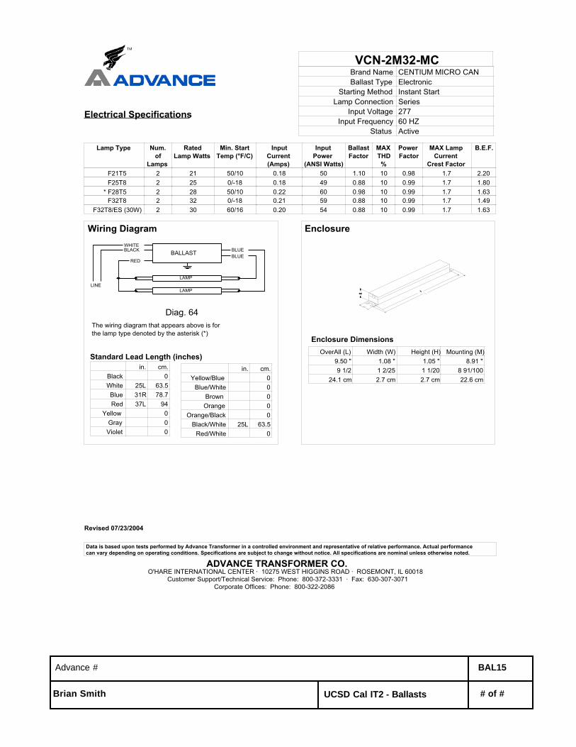
VCN-2M32-MCBrand Name CENTIUM MICRO CANBallast Type Electronic
Starting Method Instant StartLamp Connection Series
Input Voltage 277Input Frequency 60 HZ
Status Active
Electrical Specifications
Lamp Type Num.of
Lamps
RatedLamp Watts
Min. StartTemp (°F/C)
InputCurrent(Amps)
InputPower
(ANSI Watts)
BallastFactor
MAXTHD%
PowerFactor
MAX LampCurrent
Crest Factor
B.E.F.
F21T5 2 21 50/10 0.18 50 1.10 10 0.98 1.7 2.20 F25T8 2 25 0/-18 0.18 49 0.88 10 0.99 1.7 1.80* F28T5 2 28 50/10 0.22 60 0.98 10 0.99 1.7 1.63 F32T8 2 32 0/-18 0.21 59 0.88 10 0.99 1.7 1.49
F32T8/ES (30W) 2 30 60/16 0.20 54 0.88 10 0.99 1.7 1.63
Wiring Diagram
BALLAST
Diag. 64
LAMP
WHITEBLACK
RED
BLUE
LINELAMP
BLUE
The wiring diagram that appears above is for the lamp type denoted by the asterisk (*)
Standard Lead Length (inches)in. cm.
Black 0White 25L 63.5Blue 31R 78.7Red 37L 94
Yellow 0Gray 0Violet 0
in. cm.Yellow/Blue 0
Blue/White 0Brown 0Orange 0
Orange/Black 0Black/White 25L 63.5
Red/White 0
Enclosure
Enclosure Dimensions OverAll (L) Width (W) Height (H) Mounting (M)
9.50 " 1.08 " 1.05 " 8.91 "9 1/2 1 2/25 1 1/20 8 91/100
24.1 cm 2.7 cm 2.7 cm 22.6 cm
Advance # BAL15
Brian Smith UCSD Cal IT2 - Ballasts # of #
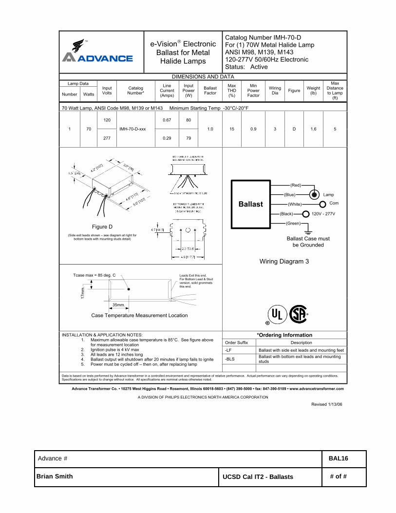
TM e-Vision Electronic Ballast for Metal Halide Lamps
Catalog Number IMH-70-D For (1) 70W Metal Halide Lamp ANSI M98, M139, M143 120-277V 50/60Hz Electronic Status: Active
DIMENSIONS AND DATA Lamp Data
Number Watts InputVolts
CatalogNumber*
LineCurrent (Amps)
InputPower
(W)
BallastFactor
Max THD(%)
MinPowerFactor
WiringDia Figure Weight
(lb)
Max Distanceto Lamp
(ft)
70 Watt Lamp, ANSI Code M98, M139 or M143 Minimum Starting Temp -30°C/-20°F
120 0.67 80
1 70
277
IMH-70-D-xxx
0.29 79
1.0 15 0.9 3 D 1.6 5
(Blue)
Ballast(Black)
(White)
(Red)
Com
120V - 277V
Ballast Case mustbe Grounded
Lamp
Wiring Diagram 3
(Green)
35mm.
17m
m.
Case Temperature Measurement Location
Tcase max = 85 deg. C Leads Exit this end.For Bottom Lead & Studversion, solid grommetsthis end.
*Ordering Information Order Suffix Description
-LF Ballast with side exit leads and mounting feet
-BLS Ballast with bottom exit leads and mounting studs
INSTALLATION & APPLICATION NOTES: 1. Maximum allowable case temperature is 85°C. See figure above
for measurement location 2. Ignition pulse is 4 kV max3. All leads are 12 inches long4. Ballast output will shutdown after 20 minutes if lamp fails to ignite5. Power must be cycled off – then on, after replacing lamp
Data is based on tests performed by Advance transformer in a controlled environment and representative of relative performance. Actual performance can vary depending on operating conditions. Specifications are subject to change without notice. All specifications are nominal unless otherwise noted.
Advance Transformer Co. • 10275 West Higgins Road • Rosemont, Illinois 60018-5603 • (847) 390-5000 • fax: 847-390-5109 • www.advancetransformer.com
A DIVISION OF PHILIPS ELECTRONICS NORTH AMERICA CORPORATION
Revised 1/13/06
Figure D(Side exit leads shown – see diagram at right for
bottom leads with mounting studs detail)
Advance # BAL16
Brian Smith UCSD Cal IT2 - Ballasts # of #
Revised 09/10/2002
Data is based upon tests performed by Advance Transformer in a controlled environment and representative of relative performance. Actual performance can vary depending on operating conditions. Specifications are subject to change without notice. All specifications are nominal unless otherwise noted.
ADVANCE TRANSFORMER CO.O'HARE INTERNATIONAL CENTER · 10275 WEST HIGGINS ROAD · ROSEMONT, IL 60018
Customer Support/Technical Service: Phone: 800-372-3331 · Fax: 630-307-3071Corporate Offices: Phone: 800-322-2086
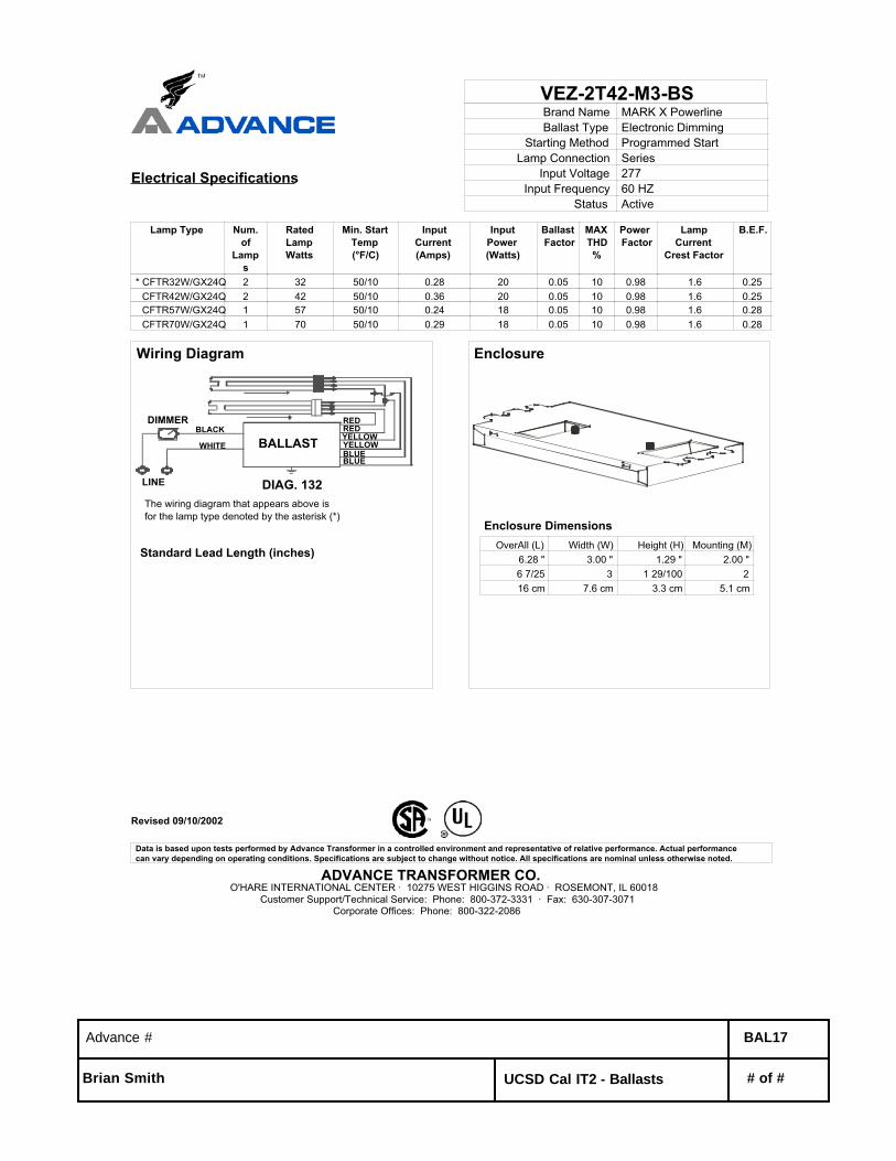
VEZ-2T42-M3-BSBrand Name MARK X PowerlineBallast Type Electronic Dimming
Starting Method Programmed StartLamp Connection Series
Input Voltage 277Input Frequency 60 HZ
Status Active
Electrical Specifications
Lamp Type Num.of
Lamps
RatedLampWatts
Min. StartTemp(°F/C)
InputCurrent(Amps)
InputPower(Watts)
Ballast Factor
MAXTHD%
Power Factor
LampCurrent
Crest Factor
B.E.F.
* CFTR32W/GX24Q 2 32 50/10 0.28 20 0.05 10 0.98 1.6 0.25 CFTR42W/GX24Q 2 42 50/10 0.36 20 0.05 10 0.98 1.6 0.25 CFTR57W/GX24Q 1 57 50/10 0.24 18 0.05 10 0.98 1.6 0.28 CFTR70W/GX24Q 1 70 50/10 0.29 18 0.05 10 0.98 1.6 0.28
Wiring Diagram
REDRED
BLUEBLUEYELLOWYELLOWBALLAST
DIAG. 132LINE
WHITE
BLACKDIMMER
The wiring diagram that appears above is for the lamp type denoted by the asterisk (*)
Standard Lead Length (inches)
Enclosure
Enclosure Dimensions OverAll (L) Width (W) Height (H) Mounting (M)
6.28 " 3.00 " 1.29 " 2.00 "6 7/25 3 1 29/100 216 cm 7.6 cm 3.3 cm 5.1 cm
Advance # BAL17
Brian Smith UCSD Cal IT2 - Ballasts # of #