Embed Size (px)
Citation preview

Bridge Converters and Faraday Screens
By Paul Wilson
Outline
Bridge Converters
Introduction
Transformer Design example
Problems with Bridge Converter Design
Possible Solutions
Schematic
Simplorer Simulation
Outline
Faraday Screens
Difficulties in switchmode power supply design
Applications to switches
Differences between Faraday Screens and Safety Screens
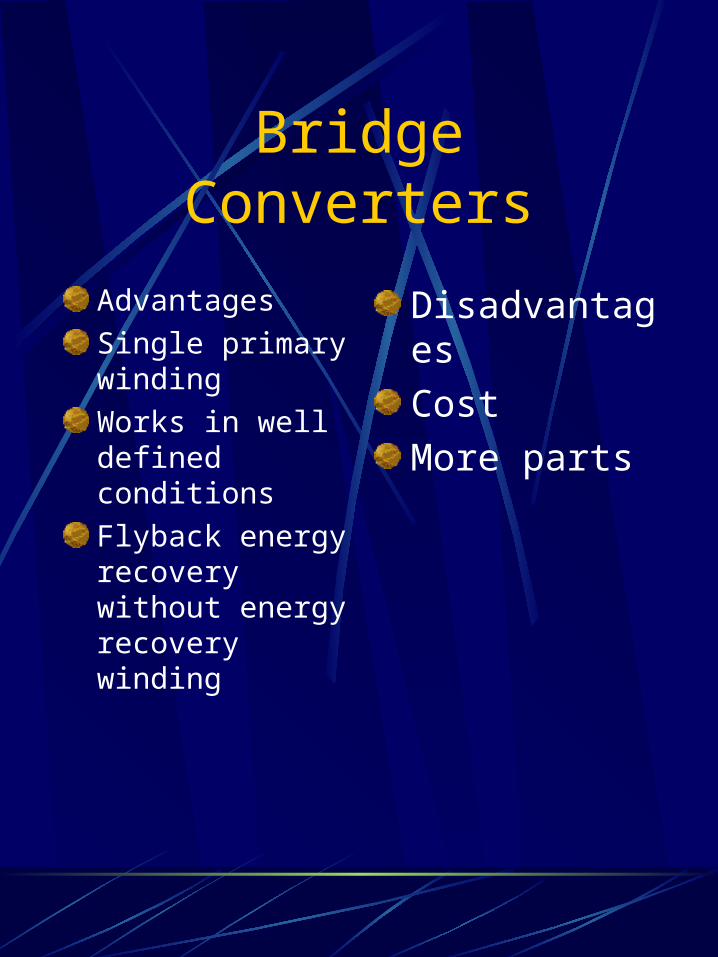
Bridge Converters
Advantages
Single primary winding
Works in well defined conditions
Flyback energy recovery without energy recovery winding
Disadvantages
Cost
More parts
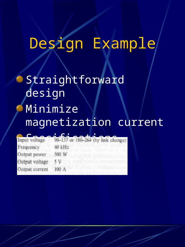
Design Example
Straightforward design
Minimize magnetization current
Specifications
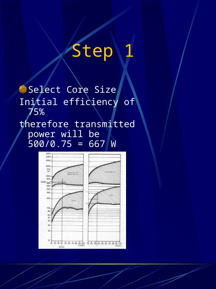
Step 1
Select Core SizeInitial efficiency of 75% therefore transmitted
power will be 500/0.75 = 667 W
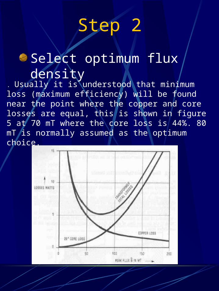
Step 2
Select optimum flux density
. Usually it is understood that minimum loss (maximum efficiency) will be found near the point where the copper and core losses are equal, this is shown in figure 5 at 70 mT where the core loss is 44%. 80 mT is normally assumed as the optimum choice.
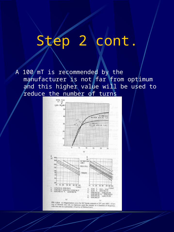
Step 2 cont.
A 100 mT is recommended by the manufacturer is not far from optimum and this higher value will be used to reduce the number of turns
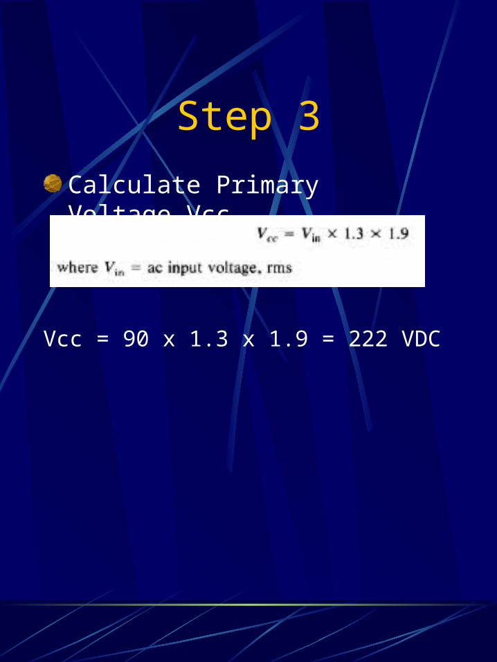
Step 3
Calculate Primary Voltage Vcc
Vcc = 90 x 1.3 x 1.9 = 222 VDC
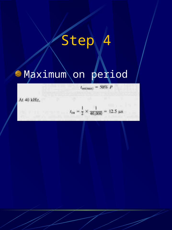
Step 4
Maximum on period
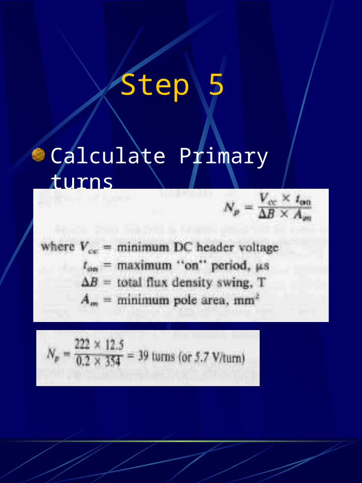
Step 5
Calculate Primary turns
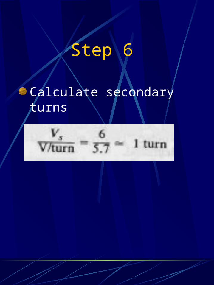
Step 6
Calculate secondary turns
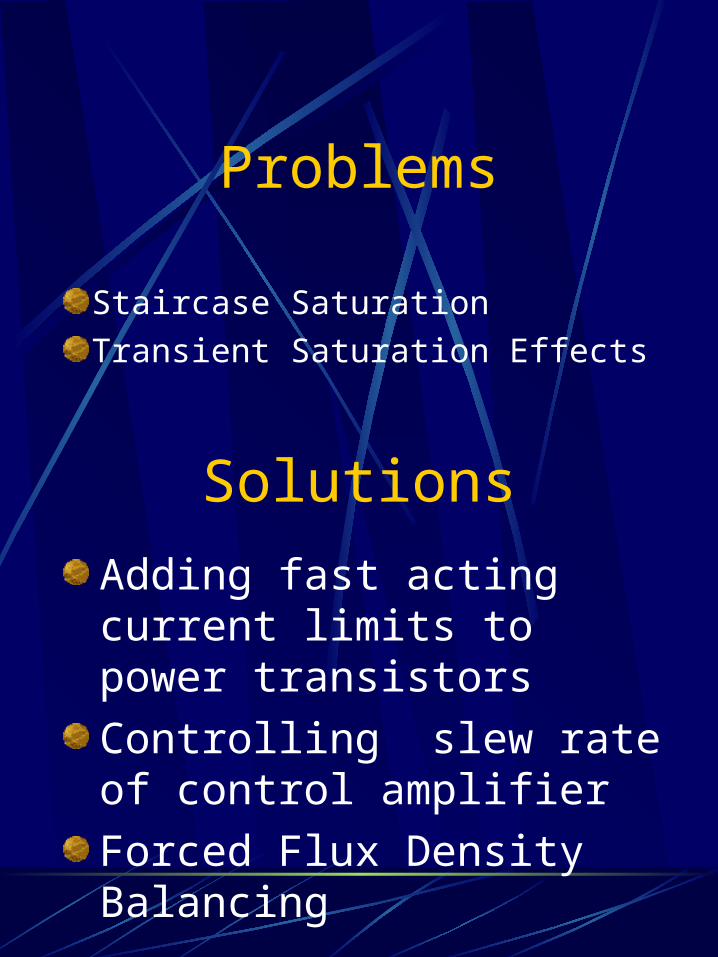
Problems
Staircase Saturation
Transient Saturation Effects
Solutions
Adding fast acting current limits to power transistors
Controlling slew rate of control amplifier
Forced Flux Density Balancing
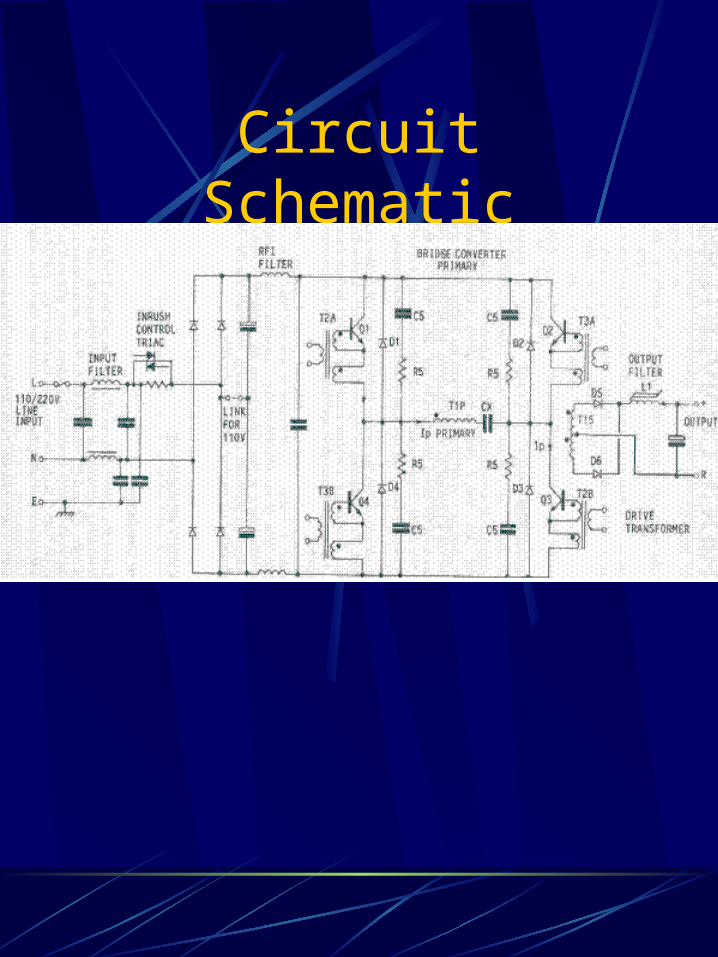
Circuit Schematic
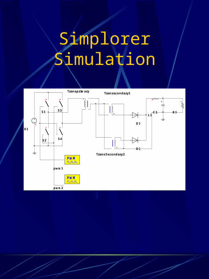
Simplorer Simulation
E1
TransprimaryTransecondary1
TransSecondary2
S1
S2
S3
S4
D1
D2
C1 R1L1
PWM
pwm1
PWM
pwm2
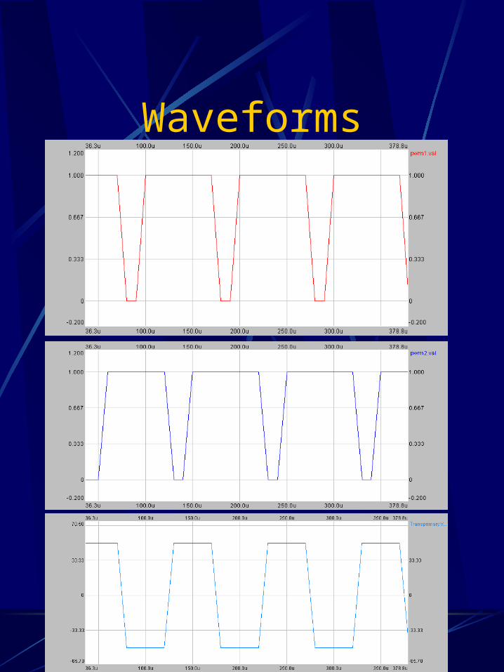
Waveforms
Faraday Screens
Difficulties in switchmode power supply design
Reducing RFI and EMI noise
Components that are thermally linked to chassis
Applied to high-frequency and high-voltage
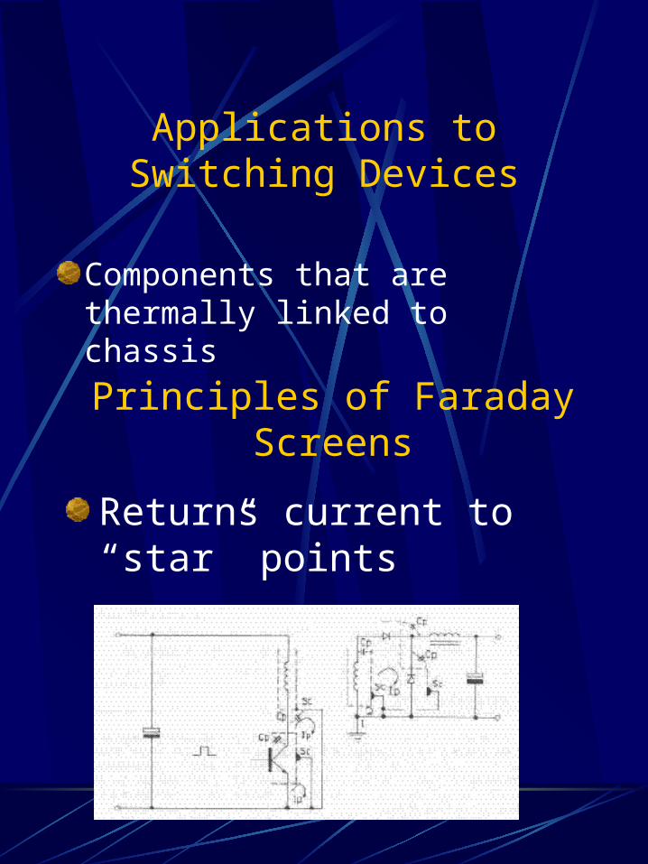
Applications to Switching Devices
Components that are thermally linked to chassis
Principles of Faraday Screens
Returns current to “star” points
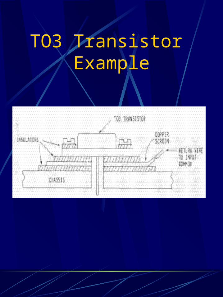
TO3 Transistor Example
Faraday Screens Vs Safety Screens
Location
Rating
Structure
Return to input or output circuits
Made of light weight copper
Small Current
Return to chassis
Made of more durable material
Rated to 3 times supply fuse rating
Faraday Screens
Safety Screens
Faraday Screen Considerations
Only use when necessary
Application results in lower power efficiency