Embed Size (px)
Citation preview
Worked examples on BRIDGE DESIGN with EUROCODES, 17-18 April 2013, St.Petersburg 1
EU-Russia Regulatory Dialogue
Construction Sector Subgroup
Bridge deck modelling and design
process for bridges
Application to a composite twin-girder bridge
according to Eurocode 4
Laurence Davaine
PhD, Bridge structural engineer, INGEROP, Paris, France
2 Worked examples on BRIDGE DESIGN with EUROCODES, 17-18 April 2013, St.Petersburg
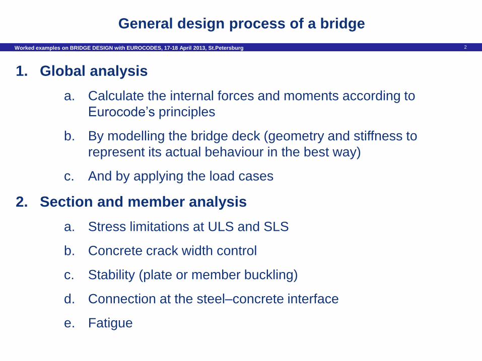
1. Global analysis
a. Calculate the internal forces and moments according to
Eurocode’s principles
b. By modelling the bridge deck (geometry and stiffness to
represent its actual behaviour in the best way)
c. And by applying the load cases
2. Section and member analysis
a. Stress limitations at ULS and SLS
b. Concrete crack width control
c. Stability (plate or member buckling)
d. Connection at the steel–concrete interface
e. Fatigue
General design process of a bridge
3 Worked examples on BRIDGE DESIGN with EUROCODES, 17-18 April 2013, St.Petersburg
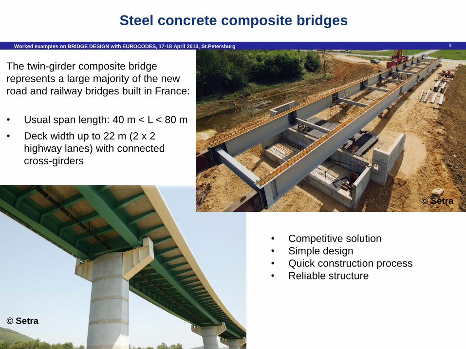
Steel concrete composite bridges
The twin-girder composite bridge
represents a large majority of the new
road and railway bridges built in France:
• Usual span length: 40 m < L < 80 m
• Deck width up to 22 m (2 x 2
highway lanes) with connected
cross-girders
• Competitive solution
• Simple design
• Quick construction process
• Reliable structure
© Setra
© Setra
4 Worked examples on BRIDGE DESIGN with EUROCODES, 17-18 April 2013, St.Petersburg
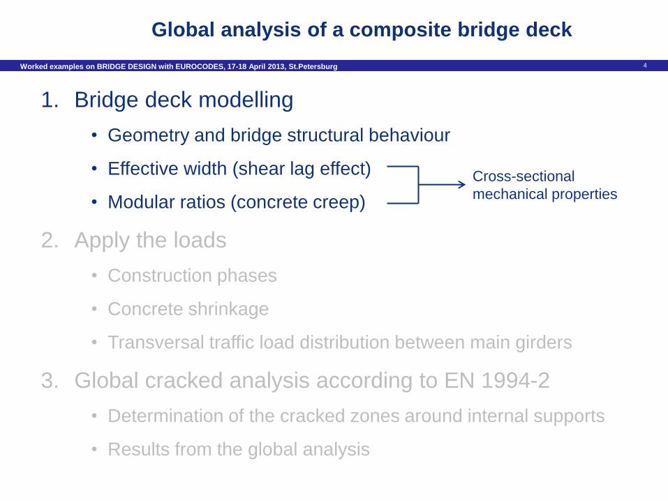
Global analysis of a composite bridge deck
1. Bridge deck modelling
• Geometry and bridge structural behaviour
• Effective width (shear lag effect)
• Modular ratios (concrete creep)
2. Apply the loads
• Construction phases
• Concrete shrinkage
• Transversal traffic load distribution between main girders
3. Global cracked analysis according to EN 1994-2
• Determination of the cracked zones around internal supports
• Results from the global analysis
Cross-sectional
mechanical properties
5 Worked examples on BRIDGE DESIGN with EUROCODES, 17-18 April 2013, St.Petersburg
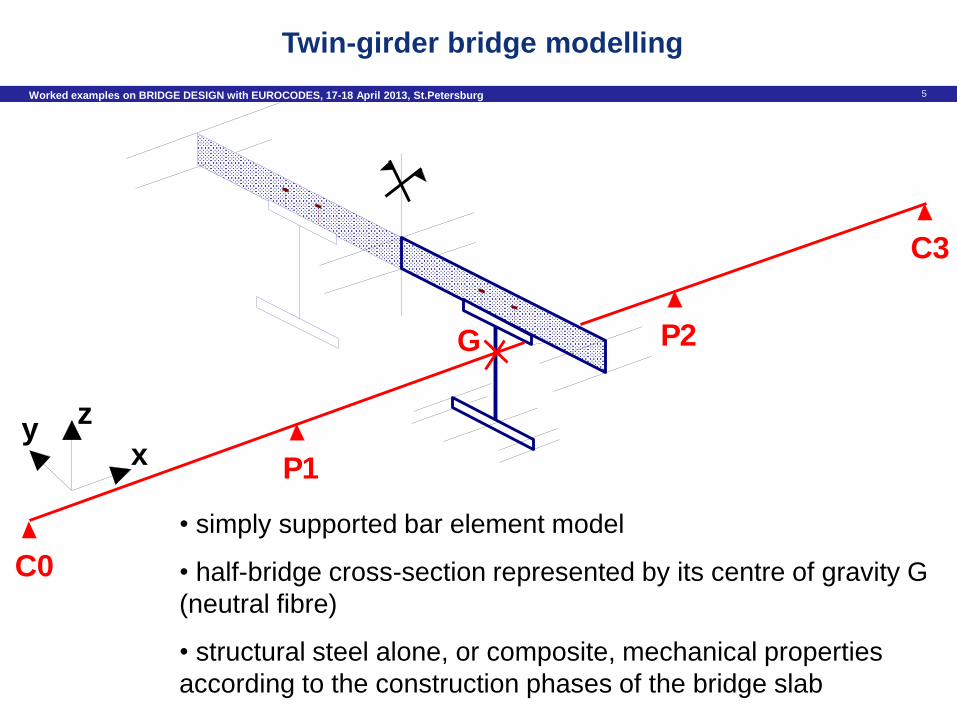
Twin-girder bridge modelling
• simply supported bar element model
• half-bridge cross-section represented by its centre of gravity G
(neutral fibre)
• structural steel alone, or composite, mechanical properties
according to the construction phases of the bridge slab
G
C0
P1
P2
C3
x
zy
6 Worked examples on BRIDGE DESIGN with EUROCODES, 17-18 April 2013, St.Petersburg
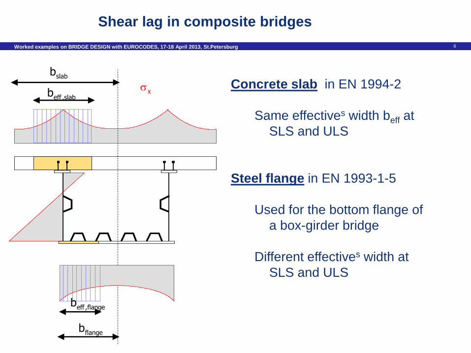
Concrete slab in EN 1994-2
Same effectives width beff at
SLS and ULS
Steel flange in EN 1993-1-5
Used for the bottom flange of
a box-girder bridge
Different effectives width at
SLS and ULS
eff ,flangeb
flangeb
eff ,slabb
slabb
x
Shear lag in composite bridges
7 Worked examples on BRIDGE DESIGN with EUROCODES, 17-18 April 2013, St.Petersburg
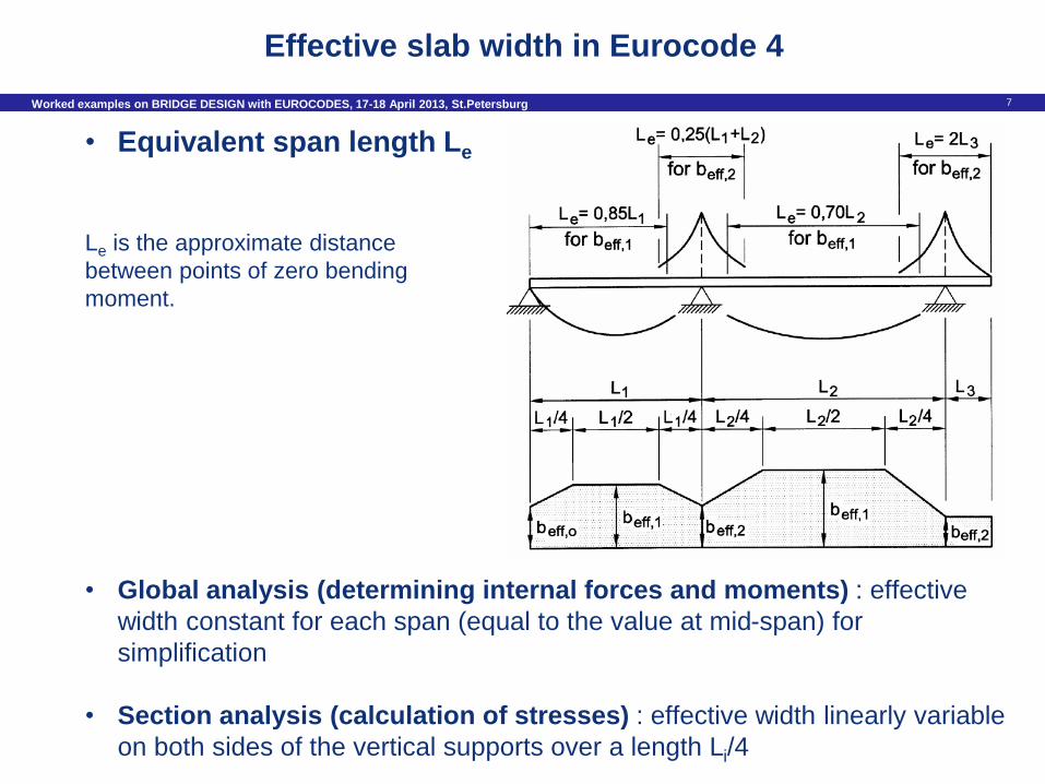
Effective slab width in Eurocode 4
• Global analysis (determining internal forces and moments) : effective
width constant for each span (equal to the value at mid-span) for
simplification
• Section analysis (calculation of stresses) : effective width linearly variable
on both sides of the vertical supports over a length Li/4
• Equivalent span length Le
Le is the approximate distance
between points of zero bending
moment.
8 Worked examples on BRIDGE DESIGN with EUROCODES, 17-18 April 2013, St.Petersburg
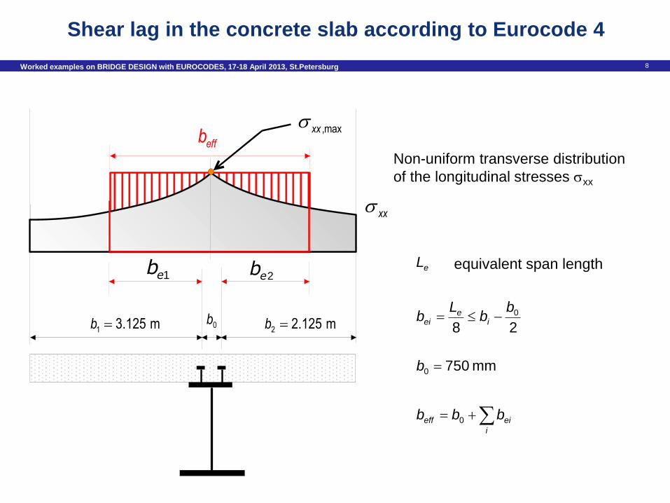
Shear lag in the concrete slab according to Eurocode 4
Non-uniform transverse distribution
of the longitudinal stresses xx
mm 7500 b
i
eieff bbb 0
280b
bL
b ie
ei
eL equivalent span length
effb
xx
1 3.125 mb 2 2.125 mb
,maxxx
0b
xy
1eb 2eb
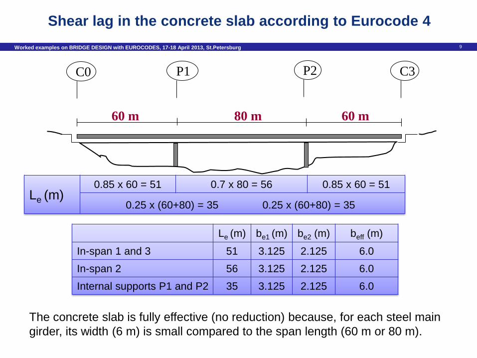
9 Worked examples on BRIDGE DESIGN with EUROCODES, 17-18 April 2013, St.Petersburg
60 m 80 m 60 m
C0 P1 C3 P2
Le (m) 0.85 x 60 = 51 0.7 x 80 = 56 0.85 x 60 = 51
0.25 x (60+80) = 35
Le (m) be1 (m) be2 (m) beff (m)
In-span 1 and 3 51 3.125 2.125 6.0
In-span 2 56 3.125 2.125 6.0
Internal supports P1 and P2 35 3.125 2.125 6.0
0.25 x (60+80) = 35
The concrete slab is fully effective (no reduction) because, for each steel main
girder, its width (6 m) is small compared to the span length (60 m or 80 m).
Shear lag in the concrete slab according to Eurocode 4
10 Worked examples on BRIDGE DESIGN with EUROCODES, 17-18 April 2013, St.Petersburg
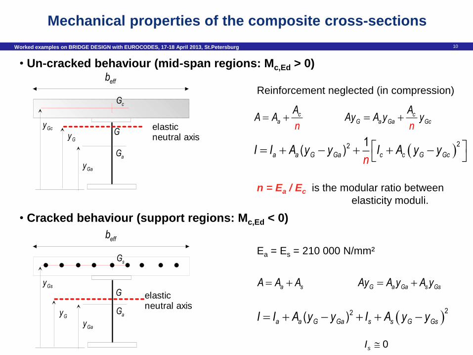
Mechanical properties of the composite cross-sections
caA A
n
A
22 1
( )a a G Ga c c G GcI I A y y I A yn
y
effb
elastic neutral axis
cG
aG
G
Gay
GyGcy
• Un-cracked behaviour (mid-span regions: Mc,Ed > 0)
• Cracked behaviour (support regions: Mc,Ed < 0)
Reinforcement neglected (in compression)
effb
elastic neutral axis
sG
aG
G
GayGy
Gsy
Ea = Es = 210 000 N/mm²
cG a Ga Gc
AAy A y
ny
a sA A A G a Ga s GsAy A y A y
22( )a a G Ga s s G GsI I A y y I A y y
0sI
n = Ea / Ec is the modular ratio between
elasticity moduli.
11 Worked examples on BRIDGE DESIGN with EUROCODES, 17-18 April 2013, St.Petersburg
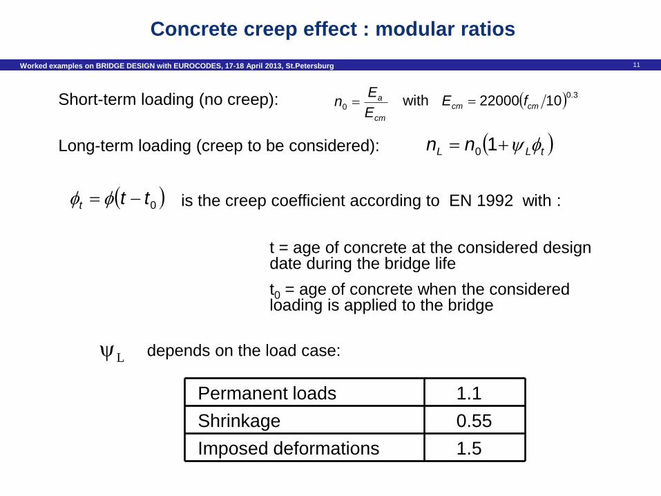
t = age of concrete at the considered design date during the bridge life
t0 = age of concrete when the considered loading is applied to the bridge
L depends on the load case:
Permanent loads
Shrinkage
Imposed deformations
1.1
0.55
1.5
Concrete creep effect : modular ratios
Short-term loading (no creep):
Long-term loading (creep to be considered):
is the creep coefficient according to EN 1992 with :
cm
a
E
En 0
with 3.01022000 cmcm fE
tLL nn 10
0ttt
12 Worked examples on BRIDGE DESIGN with EUROCODES, 17-18 April 2013, St.Petersburg
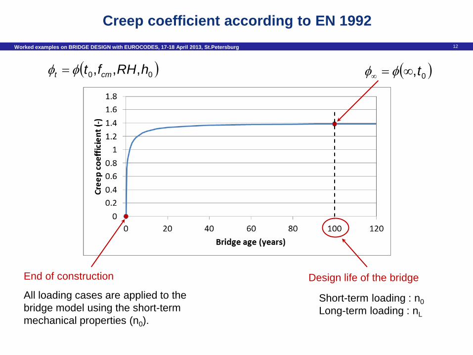
Creep coefficient according to EN 1992
Design life of the bridge End of construction
All loading cases are applied to the
bridge model using the short-term
mechanical properties (n0).
00 ,,, hRHft cmt 0,t
Short-term loading : n0
Long-term loading : nL
13 Worked examples on BRIDGE DESIGN with EUROCODES, 17-18 April 2013, St.Petersburg
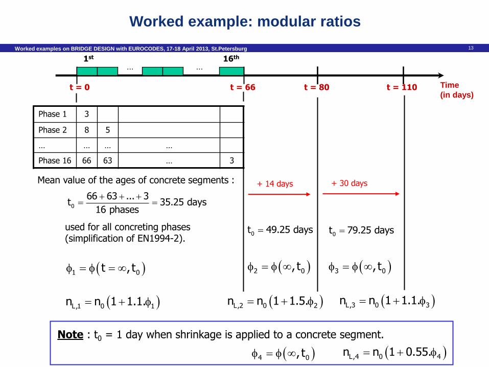
t = 0
... ... 1st 16th
Time
(in days) t = 66 t = 80 t = 110
Phase 1 3
Phase 2 8 5
… … … …
Phase 16 66 63 … 3
Mean value of the ages of concrete segments :
used for all concreting phases (simplification of EN1994-2).
0
66 63 ... 3t 35.25 days
16 phases
1 0t , t
L,1 0 1n n 1 1.1.
+ 14 days
0t 49.25 days
2 0, t
L,2 0 2n n 1 1.5.
+ 30 days
0t 79.25 days
3 0, t
L,3 0 3n n 1 1.1.
Note : t0 = 1 day when shrinkage is applied to a concrete segment.
4 0, t L,4 0 4n n 1 0.55.
Worked example: modular ratios
14 Worked examples on BRIDGE DESIGN with EUROCODES, 17-18 April 2013, St.Petersburg
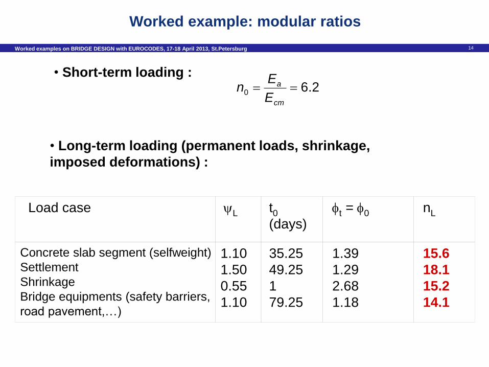
• Short-term loading :
• Long-term loading (permanent loads, shrinkage,
imposed deformations) :
Load case
L
t0
(days)
t = 0
nL
Concrete slab segment (selfweight)
Settlement
Shrinkage
Bridge equipments (safety barriers,
road pavement,…)
1.10
1.50
0.55
1.10
35.25
49.25
1
79.25
1.39
1.29
2.68
1.18
15.6
18.1
15.2
14.1
2.60 cm
a
E
En
Worked example: modular ratios
15 Worked examples on BRIDGE DESIGN with EUROCODES, 17-18 April 2013, St.Petersburg
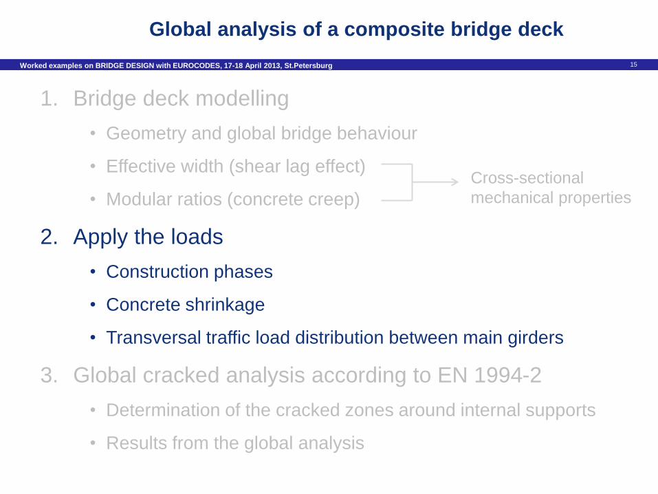
Global analysis of a composite bridge deck
1. Bridge deck modelling
• Geometry and global bridge behaviour
• Effective width (shear lag effect)
• Modular ratios (concrete creep)
2. Apply the loads
• Construction phases
• Concrete shrinkage
• Transversal traffic load distribution between main girders
3. Global cracked analysis according to EN 1994-2
• Determination of the cracked zones around internal supports
• Results from the global analysis
Cross-sectional
mechanical properties
16 Worked examples on BRIDGE DESIGN with EUROCODES, 17-18 April 2013, St.Petersburg
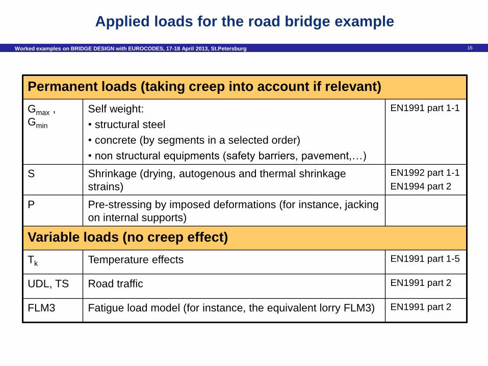
Permanent loads (taking creep into account if relevant)
Gmax ,
Gmin
Self weight:
• structural steel
• concrete (by segments in a selected order)
• non structural equipments (safety barriers, pavement,…)
EN1991 part 1-1
S Shrinkage (drying, autogenous and thermal shrinkage
strains)
EN1992 part 1-1
EN1994 part 2
P Pre-stressing by imposed deformations (for instance, jacking
on internal supports)
Variable loads (no creep effect)
Tk Temperature effects EN1991 part 1-5
UDL, TS Road traffic EN1991 part 2
FLM3 Fatigue load model (for instance, the equivalent lorry FLM3) EN1991 part 2
Applied loads for the road bridge example
17 Worked examples on BRIDGE DESIGN with EUROCODES, 17-18 April 2013, St.Petersburg
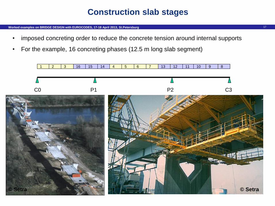
Construction slab stages
• imposed concreting order to reduce the concrete tension around internal supports
• For the example, 16 concreting phases (12.5 m long slab segment)
1 2 3 16 15 14 4 5 6 7 13 12 11 10 9 8
C0 P1 P2 C3
© Setra © Setra
18 Worked examples on BRIDGE DESIGN with EUROCODES, 17-18 April 2013, St.Petersburg
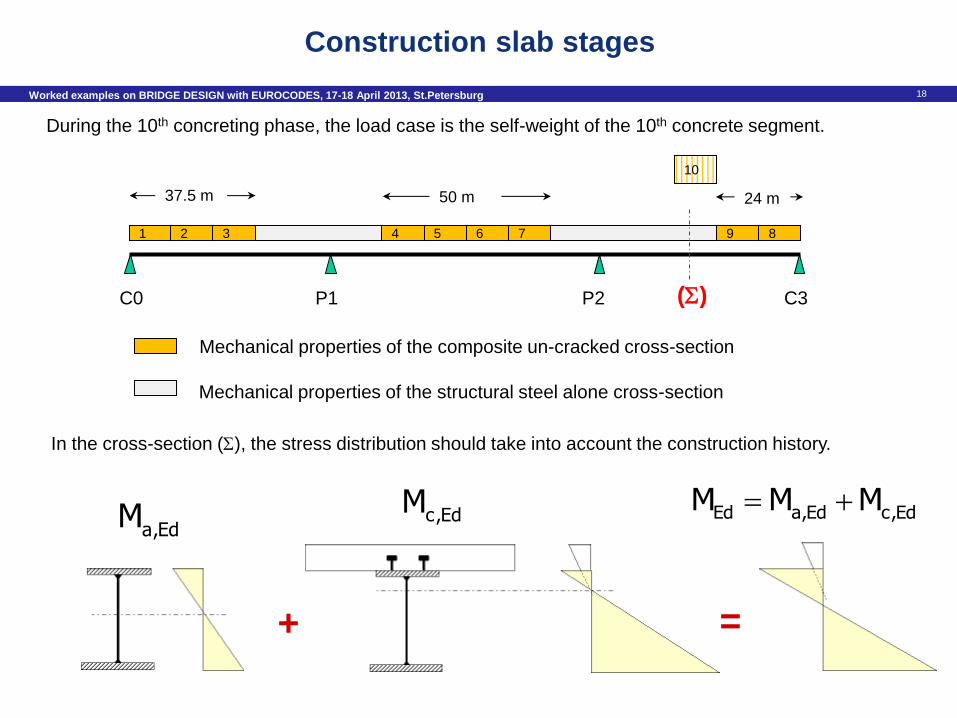
Construction slab stages
10
During the 10th concreting phase, the load case is the self-weight of the 10th concrete segment.
Mechanical properties of the composite un-cracked cross-section
Mechanical properties of the structural steel alone cross-section
C0 P1 P2 C3
1 2 3 4 5 6 7 9 8
37.5 m 50 m 24 m
()
In the cross-section (), the stress distribution should take into account the construction history.
a,EdM
+
c,EdM
=
Ed a,Ed c,EdM M M
19 Worked examples on BRIDGE DESIGN with EUROCODES, 17-18 April 2013, St.Petersburg
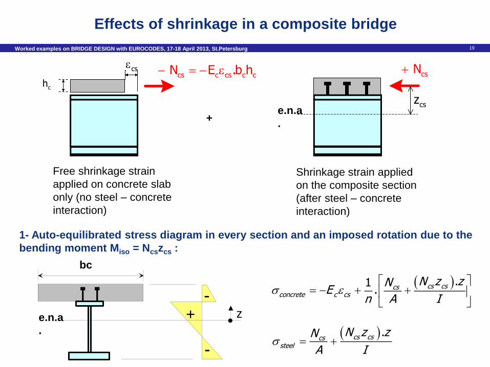
-
-
+ ze.n.a
.
bc
. cs cscs
steel
N z zN
A I
.1. cs cscs
concrete c cs
N z zNE
n A I
1- Auto-equilibrated stress diagram in every section and an imposed rotation due to the
bending moment Miso = Ncszcs :
cs
Free shrinkage strain
applied on concrete slab
only (no steel – concrete
interaction)
cs N
csze.n.a
. +
Shrinkage strain applied
on the composite section
(after steel – concrete
interaction)
cs c cs c c N E .b h
ch
Effects of shrinkage in a composite bridge
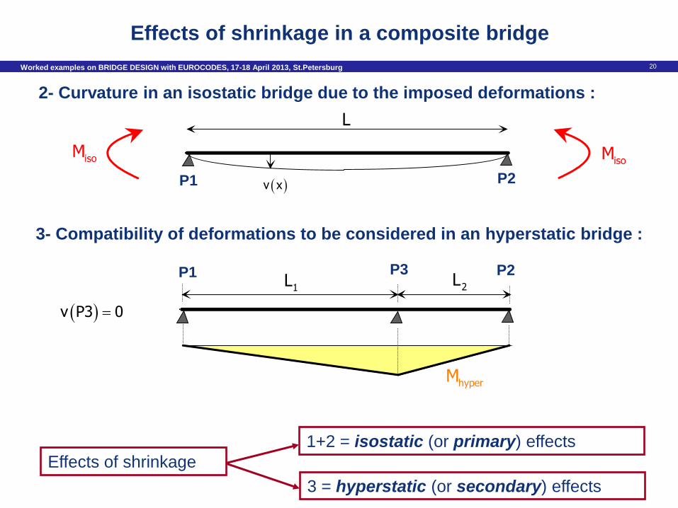
20 Worked examples on BRIDGE DESIGN with EUROCODES, 17-18 April 2013, St.Petersburg
2- Curvature in an isostatic bridge due to the imposed deformations :
3- Compatibility of deformations to be considered in an hyperstatic bridge :
isoMisoM
L
v xP1 P2
P1 P2 P3 1L 2L
hyperM
v P3 0
1+2 = isostatic (or primary) effects
Effects of shrinkage
3 = hyperstatic (or secondary) effects
Effects of shrinkage in a composite bridge
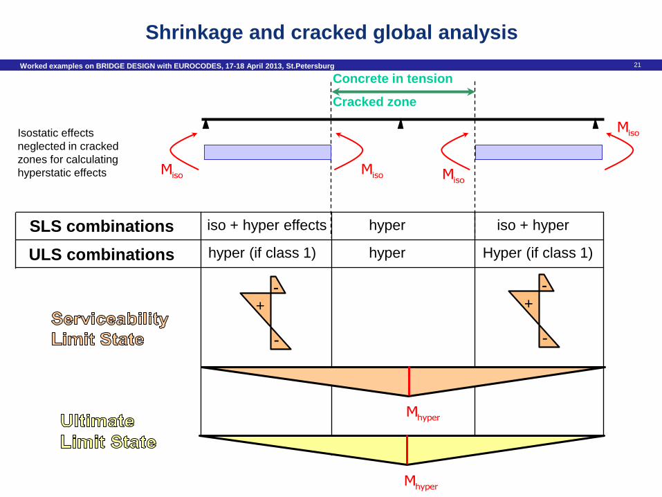
21 Worked examples on BRIDGE DESIGN with EUROCODES, 17-18 April 2013, St.Petersburg
Concrete in tension
Cracked zone
isoM isoMisoM
Isostatic effects
neglected in cracked
zones for calculating
hyperstatic effects
isoM
SLS combinations iso + hyper effects
hyper (if class 1)
hyper
hyper Hyper (if class 1)
iso + hyper
ULS combinations
hyperM
hyperM
-
-
+
-
-
+
Shrinkage and cracked global analysis
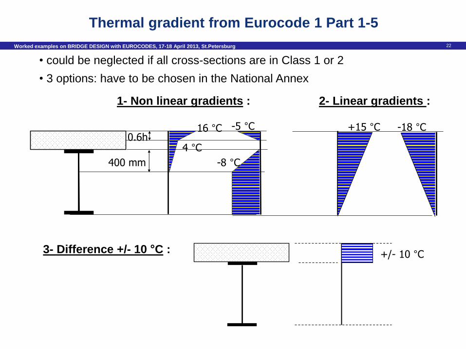
22 Worked examples on BRIDGE DESIGN with EUROCODES, 17-18 April 2013, St.Petersburg
0.6h
400 mm
16 °C
4 °C
-5 °C
-8 °C
+15 °C -18 °C
2- Linear gradients : 1- Non linear gradients :
• could be neglected if all cross-sections are in Class 1 or 2
• 3 options: have to be chosen in the National Annex
3- Difference +/- 10 °C : +/- 10 °C
Thermal gradient from Eurocode 1 Part 1-5
23 Worked examples on BRIDGE DESIGN with EUROCODES, 17-18 April 2013, St.Petersburg
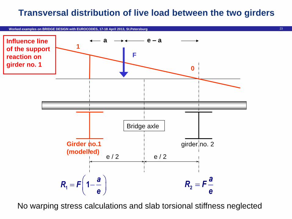
Transversal distribution of live load between the two girders
1 1 aR F
e
girder no. 2 Girder no.1
(modelled) e / 2 e / 2
Bridge axle
1
0
F
a e – a
2a
R Fe
Influence line
of the support
reaction on
girder no. 1
No warping stress calculations and slab torsional stiffness neglected
24 Worked examples on BRIDGE DESIGN with EUROCODES, 17-18 April 2013, St.Petersburg
Safe
ty b
arrie
r
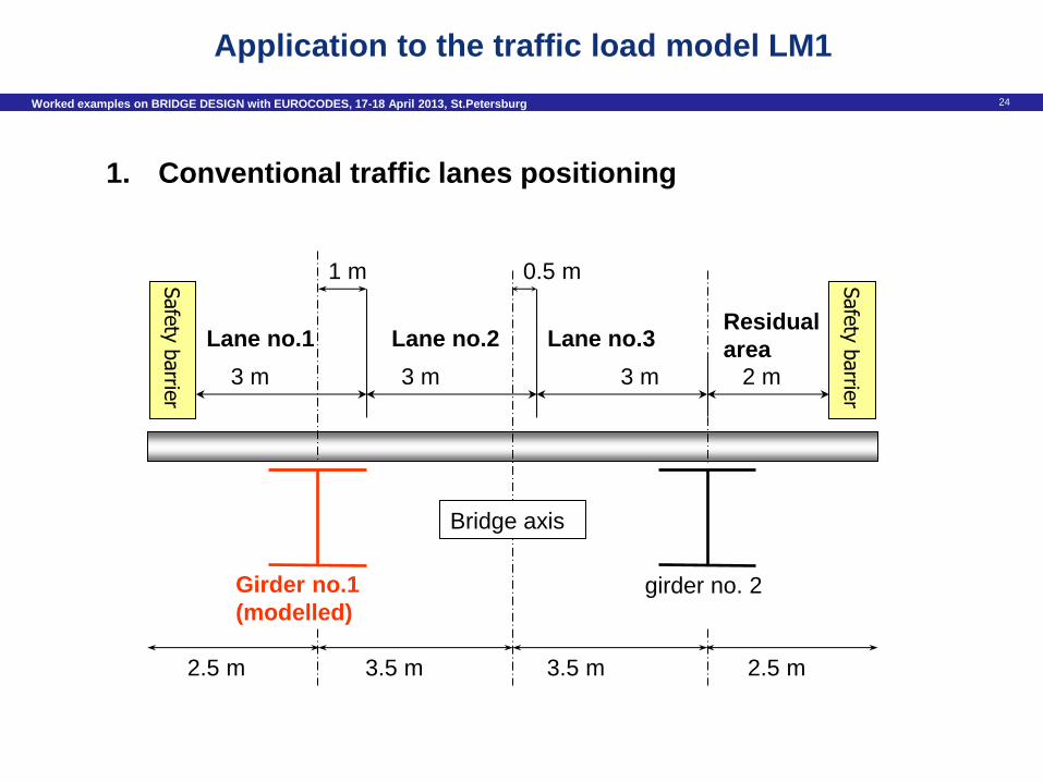
Application to the traffic load model LM1
girder no. 2 Girder no.1
(modelled)
3 m 3 m 3 m 2 m
Lane no.1 Lane no.2 Lane no.3 Residual
area
3.5 m 3.5 m
0.5 m 1 m
Bridge axis
1. Conventional traffic lanes positioning
Safe
ty b
arrie
r
2.5 m 2.5 m
25 Worked examples on BRIDGE DESIGN with EUROCODES, 17-18 April 2013, St.Petersburg
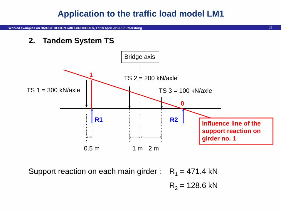
2. Tandem System TS
R1
TS 1 = 300 kN/axle
TS 2 = 200 kN/axle
TS 3 = 100 kN/axle
0
1
Influence line of the
support reaction on
girder no. 1
0.5 m
R2
1 m
Bridge axis
2 m
Support reaction on each main girder : R1 = 471.4 kN
R2 = 128.6 kN
Application to the traffic load model LM1
26 Worked examples on BRIDGE DESIGN with EUROCODES, 17-18 April 2013, St.Petersburg
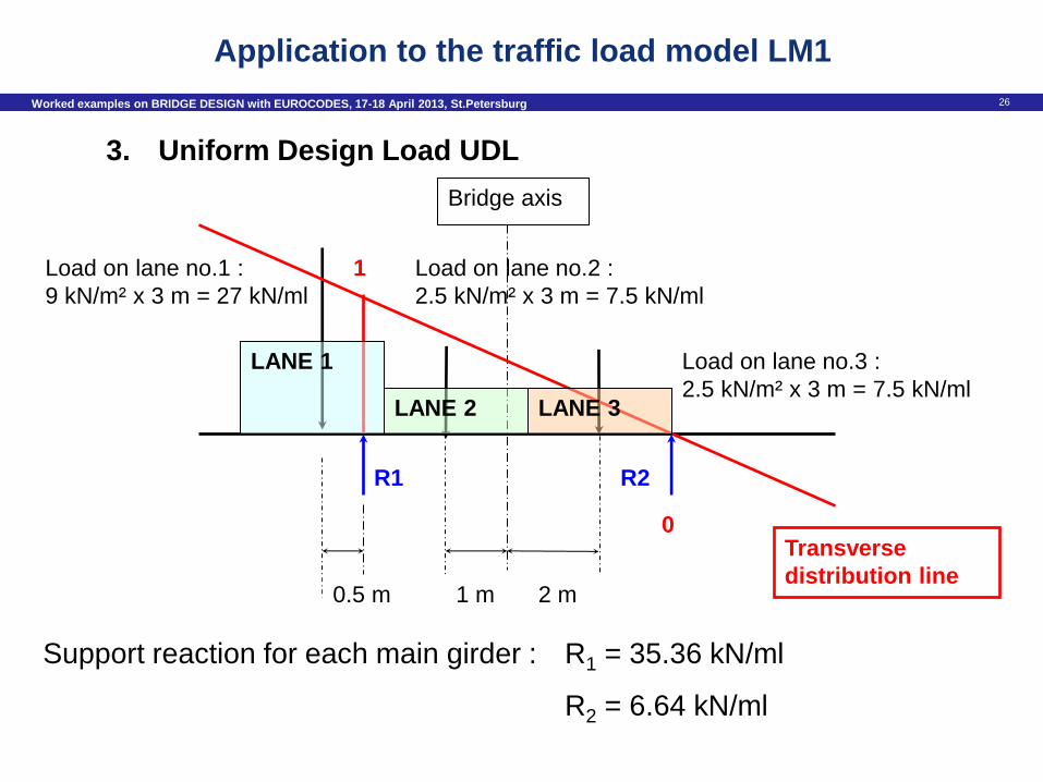
3. Uniform Design Load UDL
R1
Load on lane no.1 :
9 kN/m² x 3 m = 27 kN/ml
Load on lane no.2 :
2.5 kN/m² x 3 m = 7.5 kN/ml
Load on lane no.3 :
2.5 kN/m² x 3 m = 7.5 kN/ml
0
1
Transverse
distribution line 0.5 m
R2
1 m
Bridge axis
2 m
LANE 1
LANE 2 LANE 3
Support reaction for each main girder : R1 = 35.36 kN/ml
R2 = 6.64 kN/ml
Application to the traffic load model LM1
27 Worked examples on BRIDGE DESIGN with EUROCODES, 17-18 April 2013, St.Petersburg
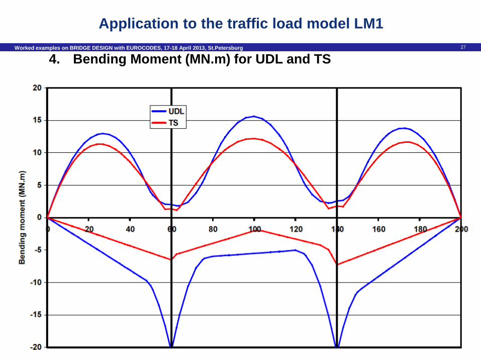
4. Bending Moment (MN.m) for UDL and TS
Application to the traffic load model LM1
28 Worked examples on BRIDGE DESIGN with EUROCODES, 17-18 April 2013, St.Petersburg
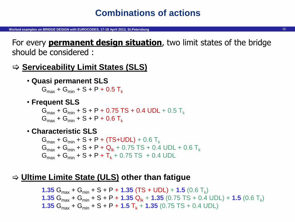
For every permanent design situation, two limit states of the bridge should be considered :
Serviceability Limit States (SLS)
• Quasi permanent SLS Gmax + Gmin + S + P + 0.5 Tk
• Frequent SLS Gmax + Gmin + S + P + 0.75 TS + 0.4 UDL + 0.5 Tk
Gmax + Gmin + S + P + 0.6 Tk
• Characteristic SLS Gmax + Gmin + S + P + (TS+UDL) + 0.6 Tk
Gmax + Gmin + S + P + Qlk + 0.75 TS + 0.4 UDL + 0.6 Tk
Gmax + Gmin + S + P + Tk + 0.75 TS + 0.4 UDL
Ultime Limite State (ULS) other than fatigue
1.35 Gmax + Gmin + S + P + 1.35 (TS + UDL) + 1.5 (0.6 Tk)
1.35 Gmax + Gmin + S + P + 1.35 Qlk + 1.35 (0.75 TS + 0.4 UDL) + 1.5 (0.6 Tk)
1.35 Gmax + Gmin + S + P + 1.5 Tk + 1.35 (0.75 TS + 0.4 UDL)
Combinations of actions
29 Worked examples on BRIDGE DESIGN with EUROCODES, 17-18 April 2013, St.Petersburg
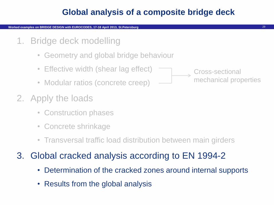
Global analysis of a composite bridge deck
1. Bridge deck modelling
• Geometry and global bridge behaviour
• Effective width (shear lag effect)
• Modular ratios (concrete creep)
2. Apply the loads
• Construction phases
• Concrete shrinkage
• Transversal traffic load distribution between main girders
3. Global cracked analysis according to EN 1994-2
• Determination of the cracked zones around internal supports
• Results from the global analysis
Cross-sectional
mechanical properties
30 Worked examples on BRIDGE DESIGN with EUROCODES, 17-18 April 2013, St.Petersburg
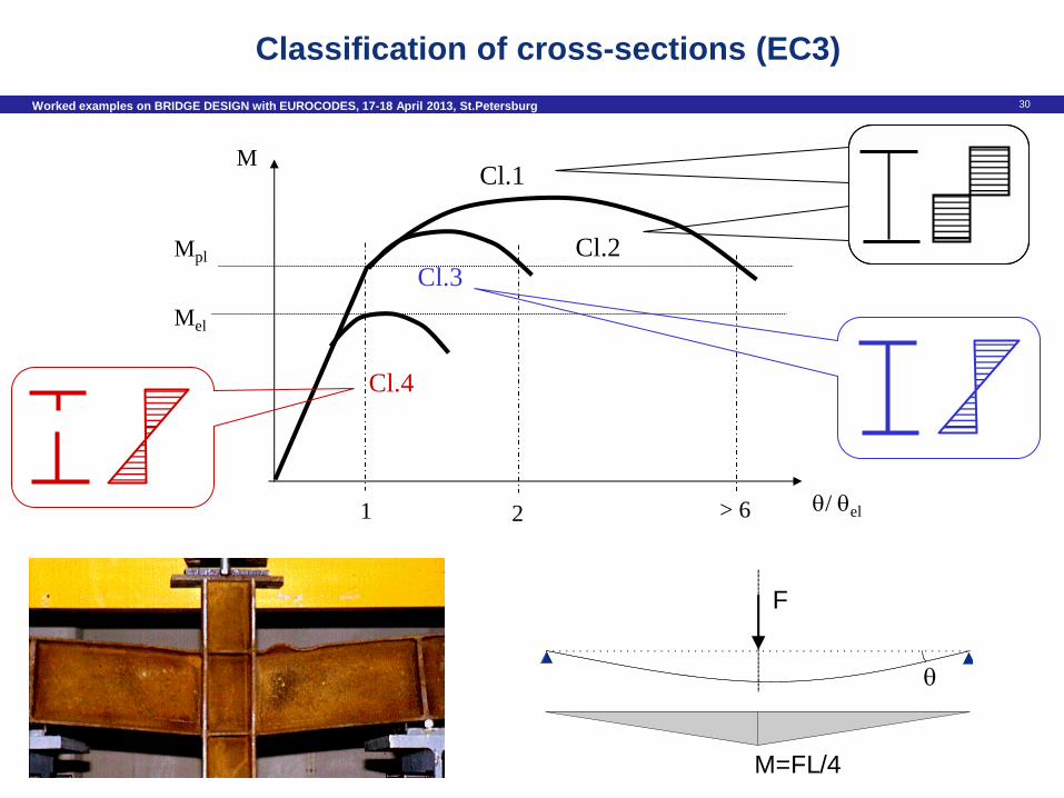
F
M = F L / 4
Cl.1
Cl.2 Cl.3
Cl.4
Mpl
Mel
/ el 1 2 > 6
M
Classification of cross-sections (EC3)
31 Worked examples on BRIDGE DESIGN with EUROCODES, 17-18 April 2013, St.Petersburg
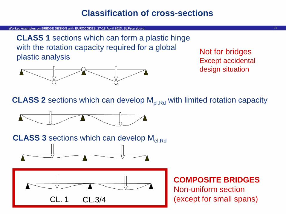
COMPOSITE BRIDGES
Non-uniform section
(except for small spans) CL. 1 CL.3/4
Classification of cross-sections
Not for bridges Except accidental
design situation
CLASS 2 sections which can develop Mpl,Rd with limited rotation capacity
CLASS 3 sections which can develop Mel,Rd
CLASS 1 sections which can form a plastic hinge
with the rotation capacity required for a global
plastic analysis
32 Worked examples on BRIDGE DESIGN with EUROCODES, 17-18 April 2013, St.Petersburg
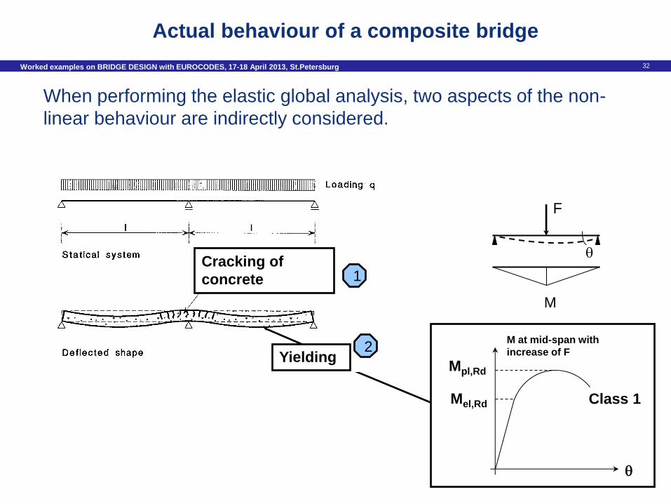
F
M
Mel,Rd
Mpl,Rd
M at mid-span with
increase of F
Class 1
Cracking of
concrete
Yielding
1
2
When performing the elastic global analysis, two aspects of the non-
linear behaviour are indirectly considered.
Actual behaviour of a composite bridge
33 Worked examples on BRIDGE DESIGN with EUROCODES, 17-18 April 2013, St.Petersburg
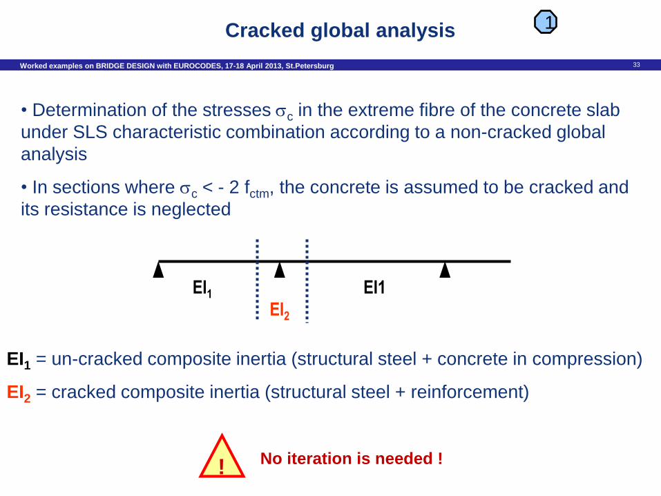
• Determination of the stresses c in the extreme fibre of the concrete slab
under SLS characteristic combination according to a non-cracked global
analysis
• In sections where c < - 2 fctm, the concrete is assumed to be cracked and
its resistance is neglected
No iteration is needed !
1
!
EI1 EI2
EI1
EI1 = un-cracked composite inertia (structural steel + concrete in compression)
EI2 = cracked composite inertia (structural steel + reinforcement)
Cracked global analysis
34 Worked examples on BRIDGE DESIGN with EUROCODES, 17-18 April 2013, St.Petersburg
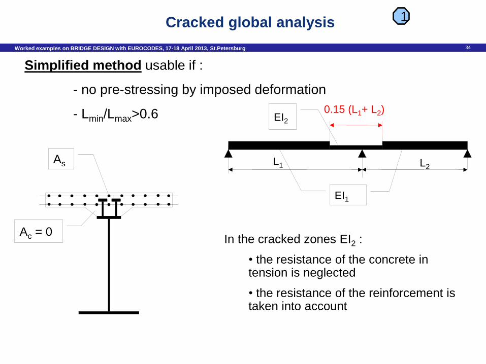
Ac = 0
As
EI2
EI1
L1 L2
0.15 (L1+ L2)
Simplified method usable if :
- no pre-stressing by imposed deformation
- Lmin/Lmax>0.6
In the cracked zones EI2 :
• the resistance of the concrete in tension is neglected
• the resistance of the reinforcement is taken into account
1 Cracked global analysis
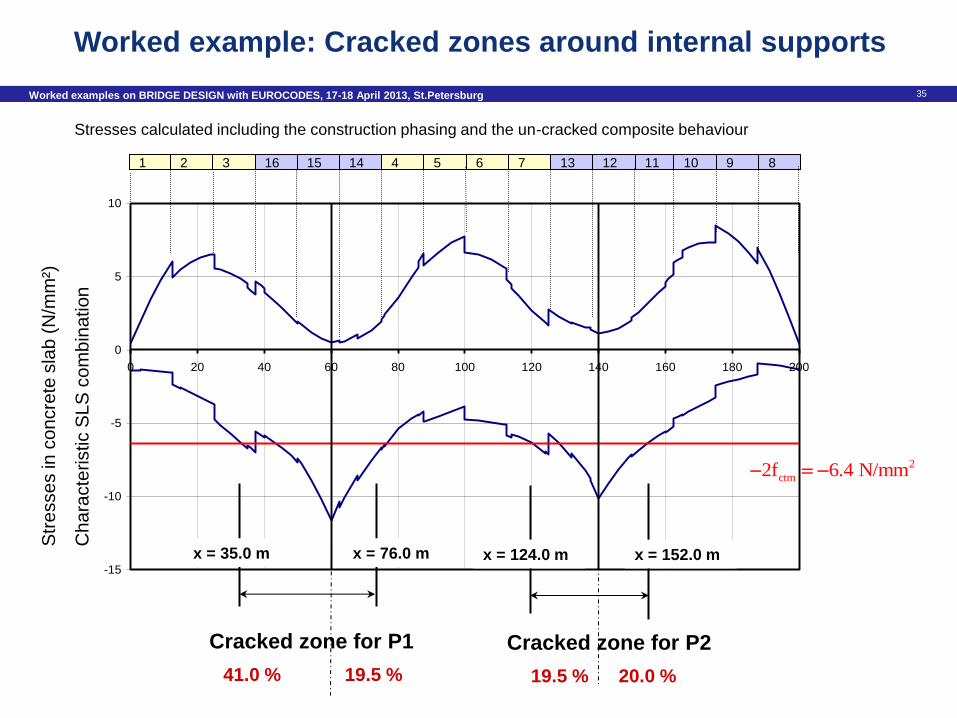
35 Worked examples on BRIDGE DESIGN with EUROCODES, 17-18 April 2013, St.Petersburg
Cracked zones for the global analysis
-15
-10
-5
0
5
10
0 20 40 60 80 100 120 140 160 180 200
2
ctm2f 6.4 N/mm
Cracked zone for P1
x = 35.0 m x = 76.0 m
41.0 % 19.5 %
Cracked zone for P2
x = 124.0 m x = 152.0 m
19.5 % 20.0 %
Str
esse
s in
co
ncre
te s
lab
(N
/mm
²)
Ch
ara
cte
ristic S
LS
co
mb
ina
tion
1 2 3 16 15 14 4 5 6 7 13 12 11 10 9 8
Stresses calculated including the construction phasing and the un-cracked composite behaviour
Worked example: Cracked zones around internal supports
36 Worked examples on BRIDGE DESIGN with EUROCODES, 17-18 April 2013, St.Petersburg
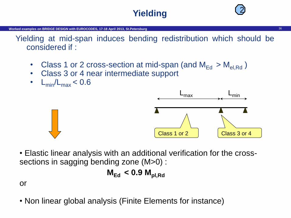
2
Yielding at mid-span induces bending redistribution which should be considered if :
• Class 1 or 2 cross-section at mid-span (and MEd > Mel,Rd ) • Class 3 or 4 near intermediate support • Lmin/Lmax < 0.6
• Elastic linear analysis with an additional verification for the cross-sections in sagging bending zone (M>0) :
MEd < 0.9 Mpl,Rd
or
• Non linear global analysis (Finite Elements for instance)
Class 1 or 2 Class 3 or 4
Lmax Lmin
Yielding
37 Worked examples on BRIDGE DESIGN with EUROCODES, 17-18 April 2013, St.Petersburg
To calculate the internal forces and moments for the ULS combination of actions – elastic global analysis (except for accidental loads) – cracking of the concrete slab – shear lag (in the concrete slab : Le/8 constant value for each span) – neglecting plate buckling (except for an effectivep area of an
element 0.5 * gross area)
To calculate the internal forces and moments for the SLS combinations of actions
– as for ULS
To calculate the longitudinal shear per unit length (SLS and ULS) at the
steel-concrete interface
– Cracked global analysis, elastic and linear – Always un-cracked section analysis
Global analysis - Synthesis
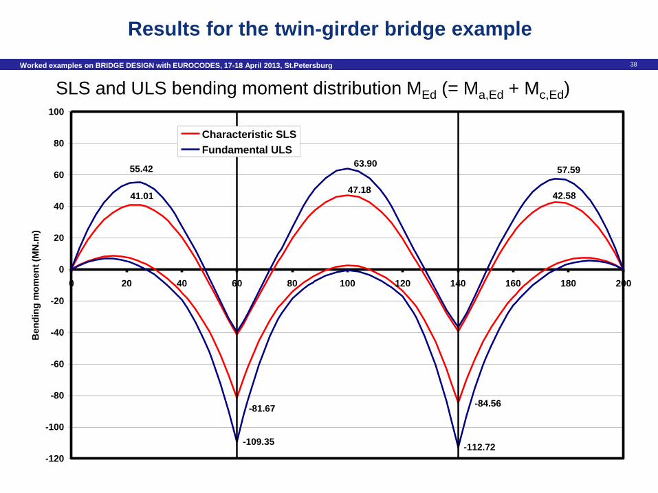
38 Worked examples on BRIDGE DESIGN with EUROCODES, 17-18 April 2013, St.Petersburg
42.5841.0147.18
-84.56-81.67
57.5955.4263.90
-112.72-109.35
-120
-100
-80
-60
-40
-20
0
20
40
60
80
100
0 20 40 60 80 100 120 140 160 180 200
Be
nd
ing
mo
me
nt
(MN
.m)
Characteristic SLS
Fundamental ULS
Results for the twin-girder bridge example
SLS and ULS bending moment distribution MEd (= Ma,Ed + Mc,Ed)
39 Worked examples on BRIDGE DESIGN with EUROCODES, 17-18 April 2013, St.Petersburg
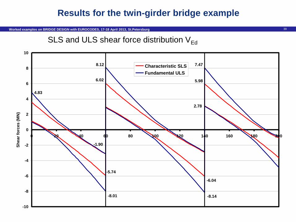
SLS and ULS shear force distribution VEd
6.02 5.98
-6.04
8.12
4.83
7.47
-1.90
-8.14-8.01
2.78
-5.74
-10
-8
-6
-4
-2
0
2
4
6
8
10
0 20 40 60 80 100 120 140 160 180 200
Sh
ear
forc
es (
MN
)
Characteristic SLS
Fundamental ULS
Results for the twin-girder bridge example
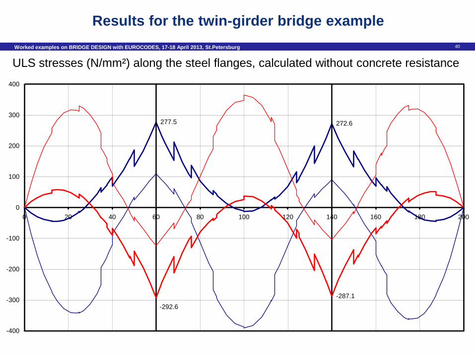
40 Worked examples on BRIDGE DESIGN with EUROCODES, 17-18 April 2013, St.Petersburg
Fondamental ULS - Flanges (extreme fiber) - Without concrete resistance
272.6277.5
-287.1
-292.6
-400
-300
-200
-100
0
100
200
300
400
0 20 40 60 80 100 120 140 160 180 200
ULS stresses (N/mm²) along the steel flanges, calculated without concrete resistance
Results for the twin-girder bridge example
41 Worked examples on BRIDGE DESIGN with EUROCODES, 17-18 April 2013, St.Petersburg
Thank you for your attention !
The results from the global analysis will be used for :
- the bridge deck cross-section analysis,
- the abutments and piers check,
- the foundation calculations,
- …