Embed Size (px)
Citation preview
BME-MIT FPGA labor
Brief Introduction to Verilog HDL (Part 1)
BUDAPEST UNIVERSITY OF TECHNOLOGY AND ECONOMICS FACULTY OF ELECTRICAL ENGINEERING AND INFORMATICS
DEPARTMENT OF MEASUREMENT AND INFORMATION SYSTEMS
Tamás Raikovich BUTE DMIS
BME-MIT FPGA labor
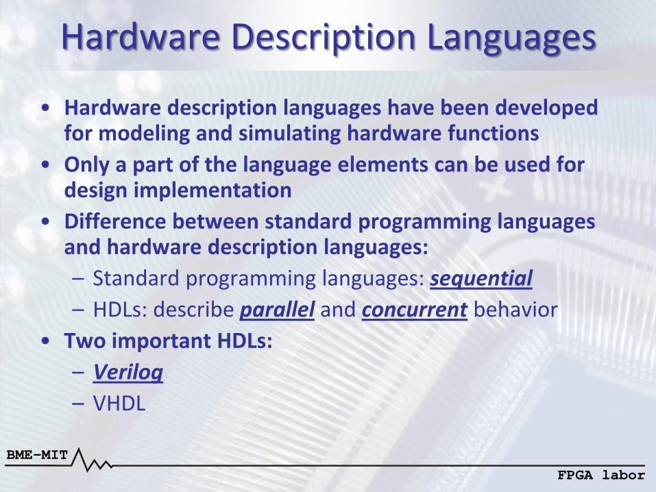
Hardware Description Languages
• Hardware description languages have been developed for modeling and simulating hardware functions
• Only a part of the language elements can be used for design implementation
• Difference between standard programming languages and hardware description languages: – Standard programming languages: sequential – HDLs: describe parallel and concurrent behavior
• Two important HDLs: – Verilog – VHDL
BME-MIT FPGA labor
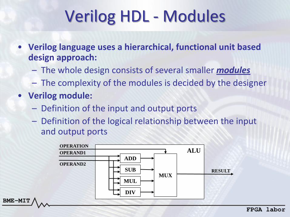
Verilog HDL - Modules
• Verilog language uses a hierarchical, functional unit based design approach: – The whole design consists of several smaller modules – The complexity of the modules is decided by the designer
• Verilog module: – Definition of the input and output ports – Definition of the logical relationship between the input
and output ports
ADD
SUB
MUL
DIV
MUX
OPERATION OPERAND1
OPERAND2 RESULT
ALU
BME-MIT FPGA labor
Verilog HDL - Modules
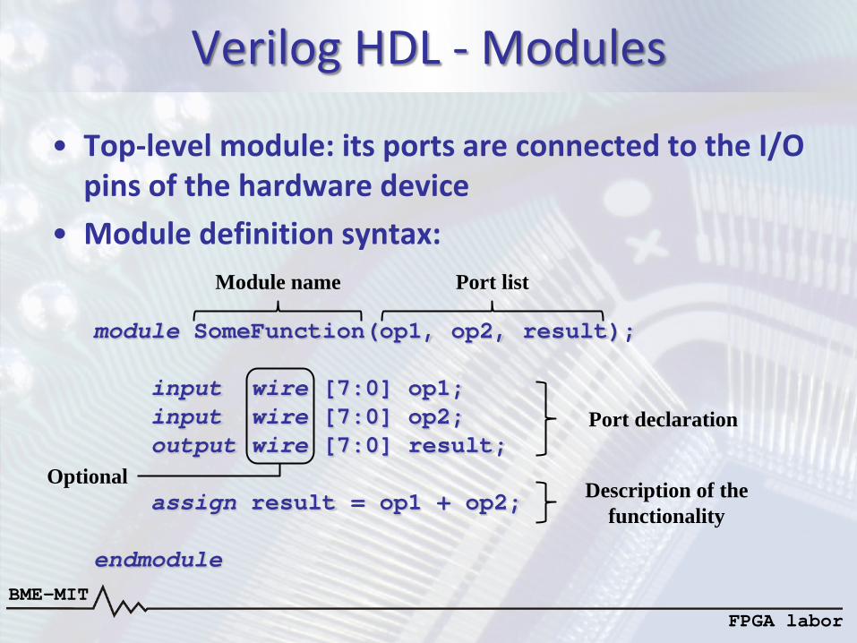
• Top-level module: its ports are connected to the I/O pins of the hardware device
• Module definition syntax:
module SomeFunction(op1, op2, result); input wire [7:0] op1; input wire [7:0] op2; output wire [7:0] result; assign result = op1 + op2; endmodule
Module name Port list
Port declaration
Description of the functionality
Optional
BME-MIT FPGA labor
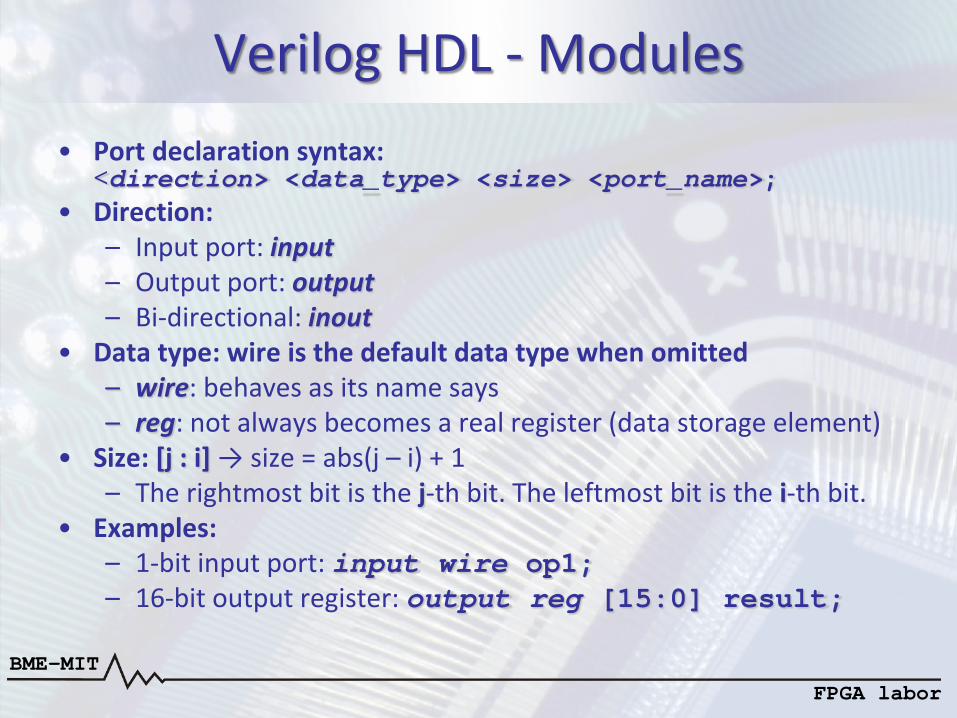
Verilog HDL - Modules • Port declaration syntax:
<direction> <data_type> <size> <port_name>; • Direction:
– Input port: input – Output port: output – Bi-directional: inout
• Data type: wire is the default data type when omitted – wire: behaves as its name says – reg: not always becomes a real register (data storage element)
• Size: [j : i] → size = abs(j – i) + 1 – The rightmost bit is the j-th bit. The leftmost bit is the i-th bit.
• Examples: – 1-bit input port: input wire op1; – 16-bit output register: output reg [15:0] result;
BME-MIT FPGA labor
Verilog HDL - Modules
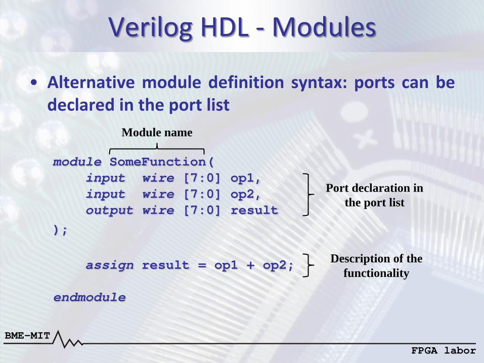
• Alternative module definition syntax: ports can be declared in the port list
module SomeFunction( input wire [7:0] op1, input wire [7:0] op2, output wire [7:0] result ); assign result = op1 + op2; endmodule
Module name
Port declaration in the port list
Description of the functionality
BME-MIT FPGA labor
Verilog HDL - Modules
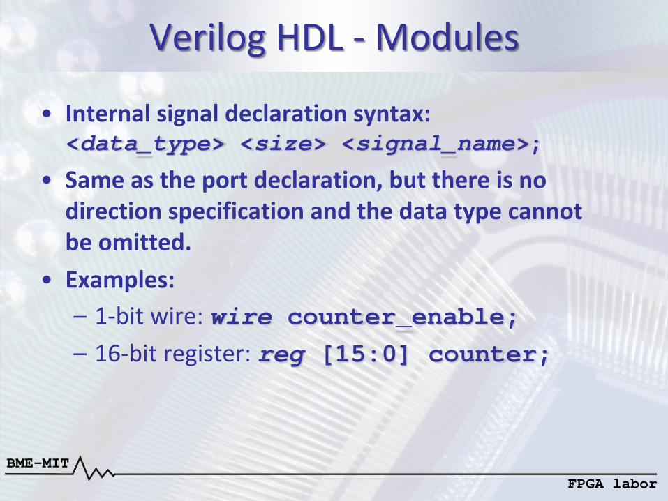
• Internal signal declaration syntax: <data_type> <size> <signal_name>;
• Same as the port declaration, but there is no direction specification and the data type cannot be omitted.
• Examples: – 1-bit wire: wire counter_enable; – 16-bit register: reg [15:0] counter;
BME-MIT FPGA labor
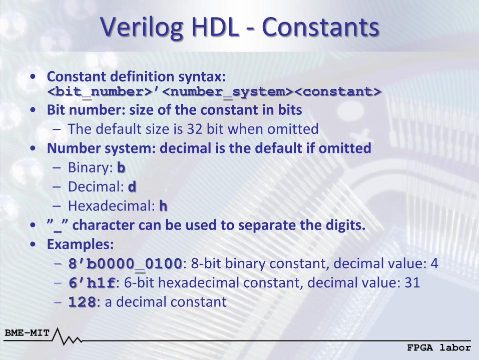
Verilog HDL - Constants • Constant definition syntax:
<bit_number>’<number_system><constant> • Bit number: size of the constant in bits
– The default size is 32 bit when omitted • Number system: decimal is the default if omitted
– Binary: b – Decimal: d – Hexadecimal: h
• ”_” character can be used to separate the digits. • Examples:
– 8’b0000_0100: 8-bit binary constant, decimal value: 4 – 6’h1f: 6-bit hexadecimal constant, decimal value: 31 – 128: a decimal constant
BME-MIT FPGA labor
Verilog HDL - Parameters
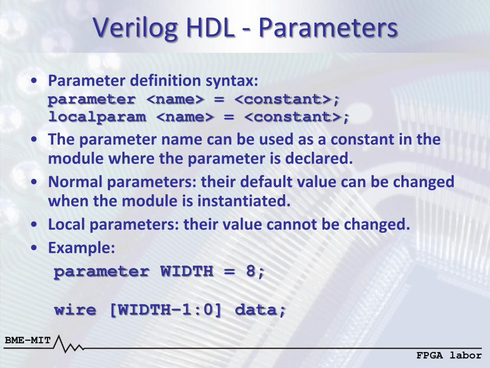
• Parameter definition syntax: parameter <name> = <constant>; localparam <name> = <constant>;
• The parameter name can be used as a constant in the module where the parameter is declared.
• Normal parameters: their default value can be changed when the module is instantiated.
• Local parameters: their value cannot be changed. • Example:
parameter WIDTH = 8; wire [WIDTH-1:0] data;
BME-MIT FPGA labor
Verilog HDL - Parameters
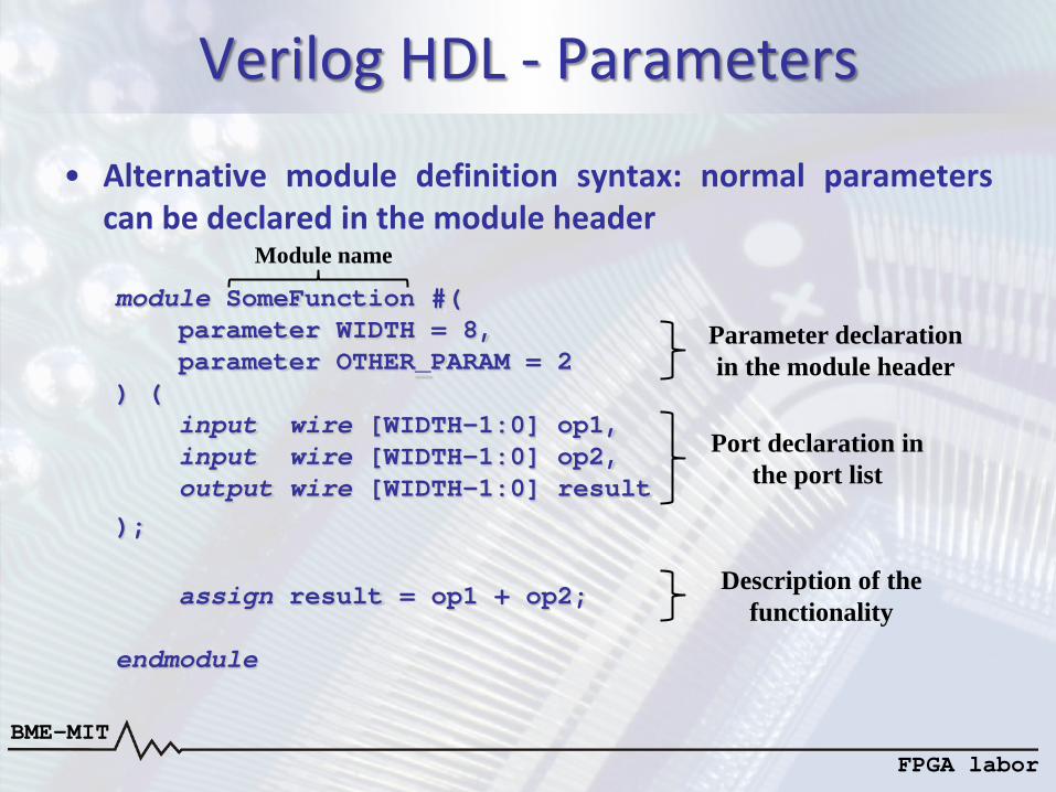
• Alternative module definition syntax: normal parameters can be declared in the module header module SomeFunction #( parameter WIDTH = 8, parameter OTHER_PARAM = 2 ) ( input wire [WIDTH-1:0] op1, input wire [WIDTH-1:0] op2, output wire [WIDTH-1:0] result ); assign result = op1 + op2; endmodule
Module name
Port declaration in the port list
Description of the functionality
Parameter declaration in the module header
BME-MIT FPGA labor
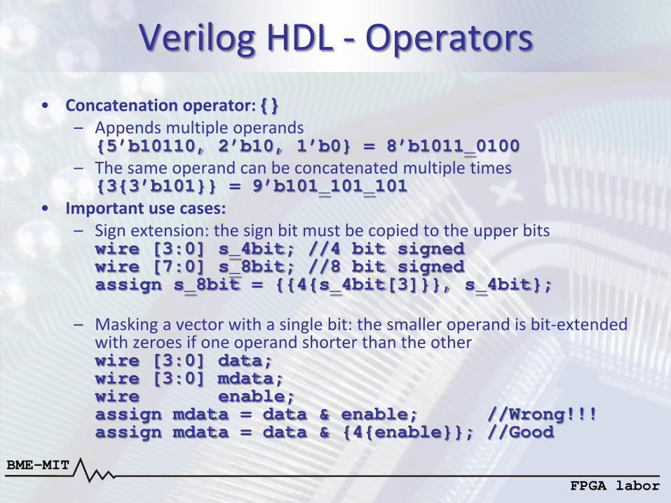
Verilog HDL - Operators • Concatenation operator: { }
– Appends multiple operands {5’b10110, 2’b10, 1’b0} = 8’b1011_0100
– The same operand can be concatenated multiple times {3{3’b101}} = 9’b101_101_101
• Important use cases: – Sign extension: the sign bit must be copied to the upper bits wire [3:0] s_4bit; //4 bit signed wire [7:0] s_8bit; //8 bit signed assign s_8bit = {{4{s_4bit[3]}}, s_4bit};
– Masking a vector with a single bit: the smaller operand is bit-extended with zeroes if one operand shorter than the other wire [3:0] data; wire [3:0] mdata; wire enable; assign mdata = data & enable; //Wrong!!! assign mdata = data & {4{enable}}; //Good
BME-MIT FPGA labor
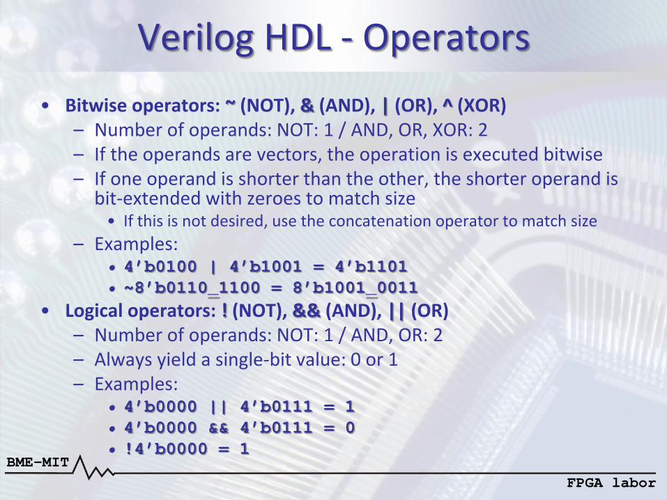
Verilog HDL - Operators • Bitwise operators: ~ (NOT), & (AND), | (OR), ^ (XOR)
– Number of operands: NOT: 1 / AND, OR, XOR: 2 – If the operands are vectors, the operation is executed bitwise – If one operand is shorter than the other, the shorter operand is
bit-extended with zeroes to match size • If this is not desired, use the concatenation operator to match size
– Examples: • 4’b0100 | 4’b1001 = 4’b1101 • ~8’b0110_1100 = 8’b1001_0011
• Logical operators: ! (NOT), && (AND), || (OR) – Number of operands: NOT: 1 / AND, OR: 2 – Always yield a single-bit value: 0 or 1 – Examples:
• 4’b0000 || 4’b0111 = 1 • 4’b0000 && 4’b0111 = 0 • !4’b0000 = 1
BME-MIT FPGA labor
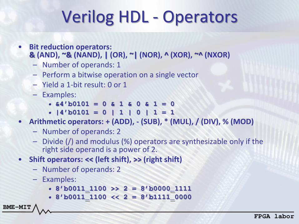
Verilog HDL - Operators • Bit reduction operators:
& (AND), ~& (NAND), | (OR), ~| (NOR), ^ (XOR), ~^ (NXOR) – Number of operands: 1 – Perform a bitwise operation on a single vector – Yield a 1-bit result: 0 or 1 – Examples:
• &4’b0101 = 0 & 1 & 0 & 1 = 0 • |4’b0101 = 0 | 1 | 0 | 1 = 1
• Arithmetic operators: + (ADD), - (SUB), * (MUL), / (DIV), % (MOD) – Number of operands: 2 – Divide (/) and modulus (%) operators are synthesizable only if the
right side operand is a power of 2. • Shift operators: << (left shift), >> (right shift)
– Number of operands: 2 – Examples:
• 8’b0011_1100 >> 2 = 8’b0000_1111 • 8’b0011_1100 << 2 = 8’b1111_0000
BME-MIT FPGA labor
Verilog HDL - Operators
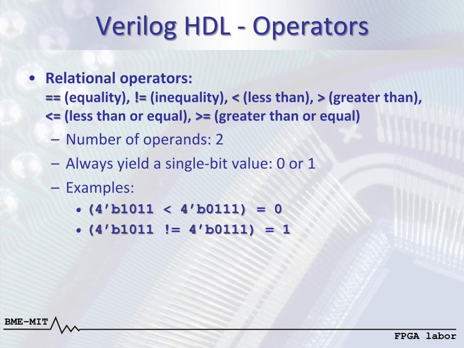
• Relational operators: == (equality), != (inequality), < (less than), > (greater than), <= (less than or equal), >= (greater than or equal) – Number of operands: 2 – Always yield a single-bit value: 0 or 1 – Examples:
• (4’b1011 < 4’b0111) = 0 • (4’b1011 != 4’b0111) = 1
BME-MIT FPGA labor
Verilog HDL - Operators
• Conditional operator: ? : <conditional_expression> ? <expression1> : <expression2>
– The conditional_expression is first evaluated • If the result is true (nonzero): expression1 is evaluated • If the result is false (zero): expression2 is evaluated
• Selecting a part of a vector: vector_name[i], vector_name[j:i]
– [i] selects the i-th bit of the vector – [j:i] selects the part between j-th bit and i-th bit
BME-MIT FPGA labor
Verilog HDL - Assignments
• Assigning value to wire type signals: assign <wire_signal> = <expression>;
– The expression is evaluated and its value is assigned to wire_signal
– Example: wire [15:0] a, b, c; assign c = a & b;
• Assigning value to reg type signals: – Value can be assigned to reg type signals in always
blocks using the <= operator
BME-MIT FPGA labor
Verilog HDL - Assignments
• Always blocks: always @(sensitivity list) assignments – The sensitivity list determines the events when the
assignments are evaluated: • always @(a, b, c): the assignments are evaluated
when the value of a, b or c changes • always @(*): the assignments are evaluated when one
of the always block input signals is changed • always @(posedge clk): the assignments are
evaluated at the rising edge of the clk signal • always @(negedge clk, posedge rst):
the assignments are evaluated at the falling edge of clk or at the rising edge of rst
BME-MIT FPGA labor
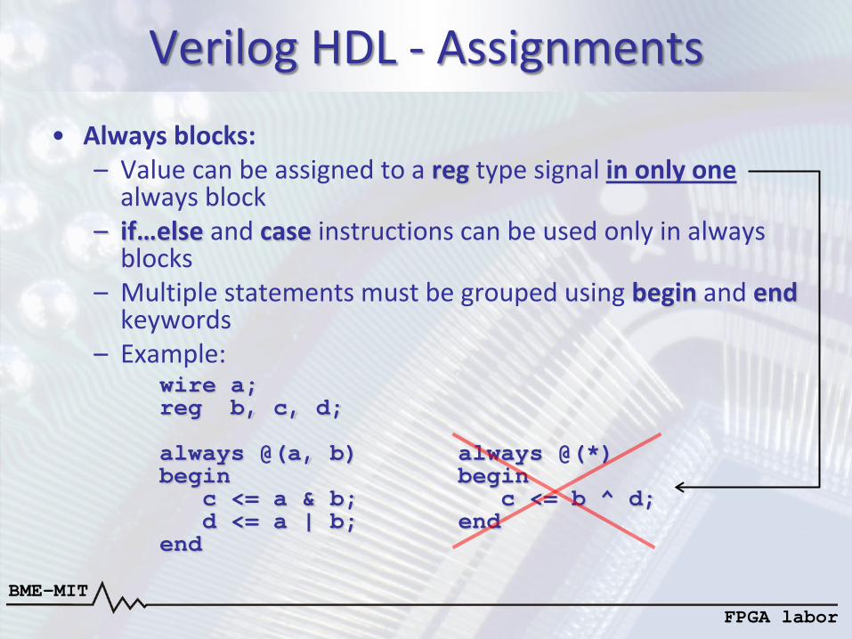
Verilog HDL - Assignments • Always blocks:
– Value can be assigned to a reg type signal in only one always block
– if…else and case instructions can be used only in always blocks
– Multiple statements must be grouped using begin and end keywords
– Example: wire a; reg b, c, d; always @(a, b) always @(*) begin begin c <= a & b; c <= b ^ d; d <= a | b; end end
BME-MIT FPGA labor
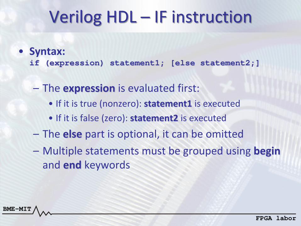
Verilog HDL – IF instruction
• Syntax: if (expression) statement1; [else statement2;]
– The expression is evaluated first: • If it is true (nonzero): statement1 is executed • If it is false (zero): statement2 is executed
– The else part is optional, it can be omitted – Multiple statements must be grouped using begin
and end keywords
BME-MIT FPGA labor
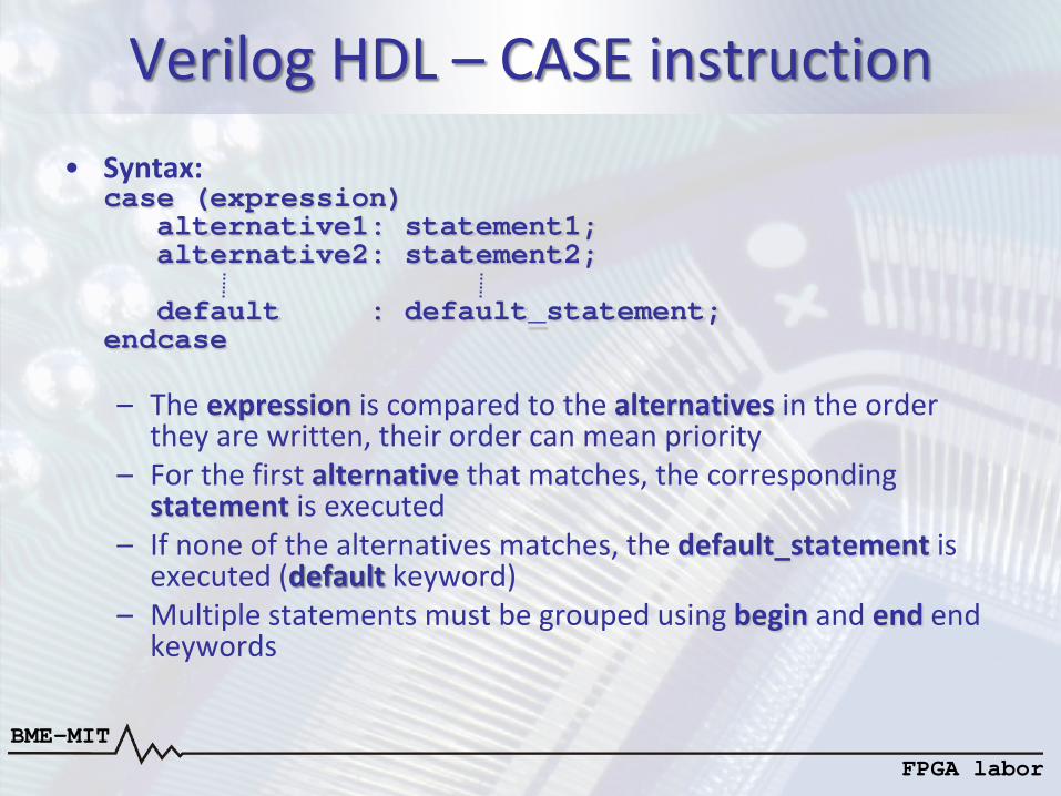
Verilog HDL – CASE instruction • Syntax:
case (expression) alternative1: statement1; alternative2: statement2; default : default_statement; endcase – The expression is compared to the alternatives in the order
they are written, their order can mean priority – For the first alternative that matches, the corresponding
statement is executed – If none of the alternatives matches, the default_statement is
executed (default keyword) – Multiple statements must be grouped using begin and end end
keywords
BME-MIT FPGA labor
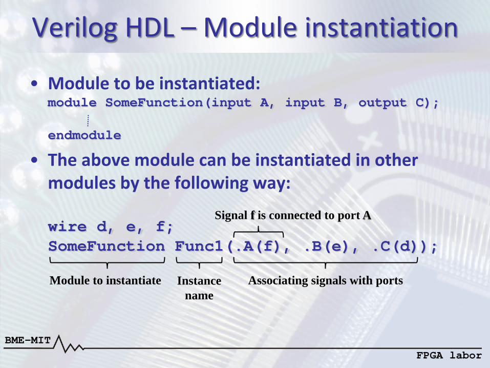
Verilog HDL – Module instantiation
• Module to be instantiated: module SomeFunction(input A, input B, output C); endmodule
• The above module can be instantiated in other modules by the following way: wire d, e, f; SomeFunction Func1(.A(f), .B(e), .C(d));
Module to instantiate Instance name
Signal f is connected to port A
Associating signals with ports
BME-MIT FPGA labor
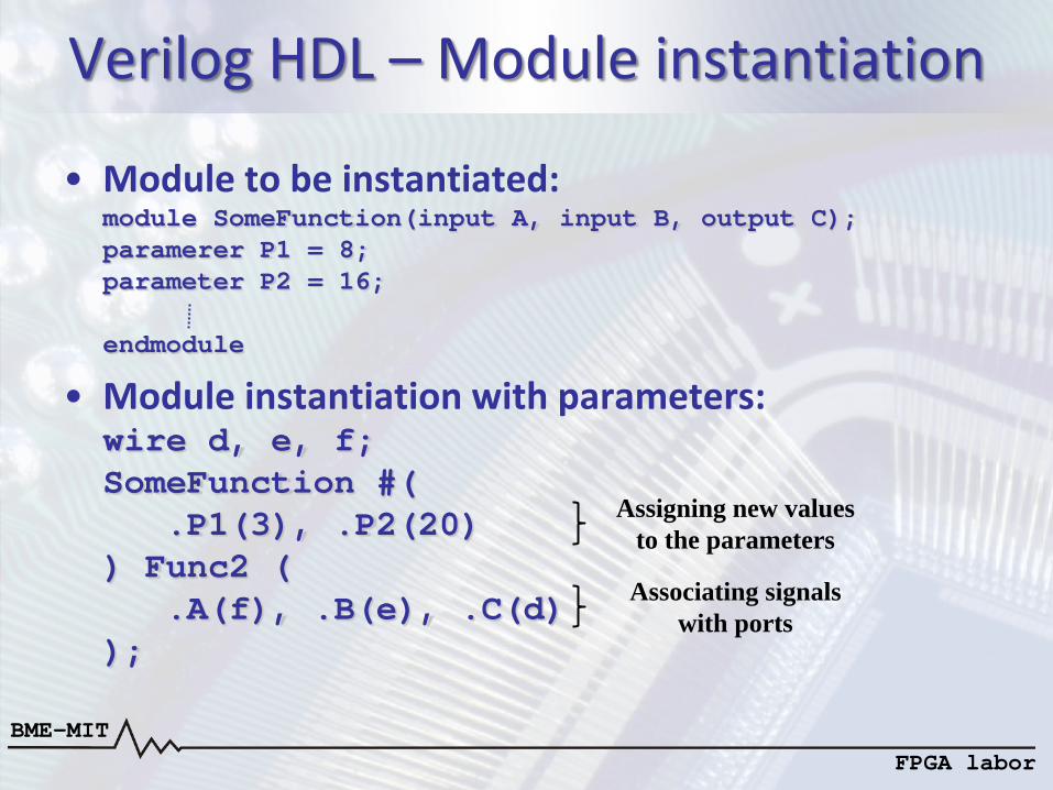
Verilog HDL – Module instantiation
• Module to be instantiated: module SomeFunction(input A, input B, output C); paramerer P1 = 8; parameter P2 = 16; endmodule
• Module instantiation with parameters: wire d, e, f; SomeFunction #( .P1(3), .P2(20) ) Func2 ( .A(f), .B(e), .C(d) );
Assigning new values to the parameters
Associating signals with ports
BME-MIT FPGA labor
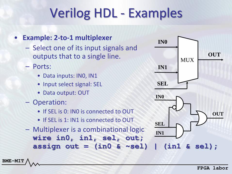
Verilog HDL - Examples
• Example: 2-to-1 multiplexer – Select one of its input signals and
outputs that to a single line. – Ports:
• Data inputs: IN0, IN1 • Input select signal: SEL • Data output: OUT
– Operation: • If SEL is 0: IN0 is connected to OUT • If SEL is 1: IN1 is connected to OUT
– Multiplexer is a combinational logic wire in0, in1, sel, out; assign out = (in0 & ~sel) | (in1 & sel);
MUX
IN0
IN1
SEL
OUT
OUT
IN0
IN1
SEL
BME-MIT FPGA labor
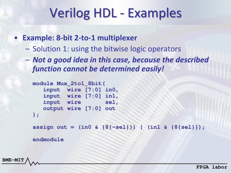
Verilog HDL - Examples
• Example: 8-bit 2-to-1 multiplexer – Solution 1: using the bitwise logic operators – Not a good idea in this case, because the described
function cannot be determined easily! module Mux_2to1_8bit( input wire [7:0] in0, input wire [7:0] in1, input wire sel, output wire [7:0] out ); assign out = (in0 & {8{~sel}}) | (in1 & {8{sel}}); endmodule
BME-MIT FPGA labor
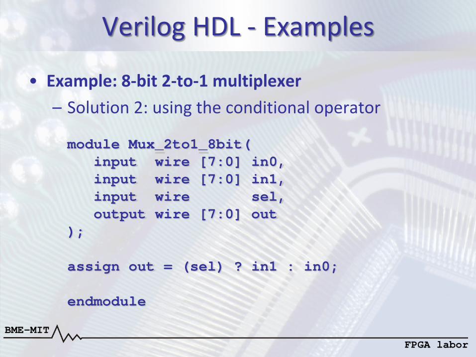
Verilog HDL - Examples
• Example: 8-bit 2-to-1 multiplexer – Solution 2: using the conditional operator module Mux_2to1_8bit( input wire [7:0] in0, input wire [7:0] in1, input wire sel, output wire [7:0] out ); assign out = (sel) ? in1 : in0; endmodule

BME-MIT FPGA labor
Verilog HDL - Examples
• Example: 8-bit 2-to-1 multiplexer – Solution 3: using the IF instruction module Mux_2to1_8bit( input wire [7:0] in0, input wire [7:0] in1, input wire sel, output reg [7:0] out ); always @(*) if (sel == 0) out <= in0; else out <= in1; endmodule
BME-MIT FPGA labor
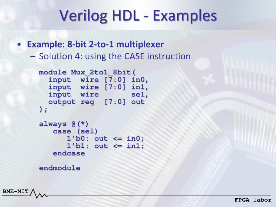
Verilog HDL - Examples
• Example: 8-bit 2-to-1 multiplexer – Solution 4: using the CASE instruction module Mux_2to1_8bit( input wire [7:0] in0, input wire [7:0] in1, input wire sel, output reg [7:0] out ); always @(*) case (sel) 1’b0: out <= in0; 1’b1: out <= in1; endcase endmodule
BME-MIT FPGA labor
Verilog HDL - Examples
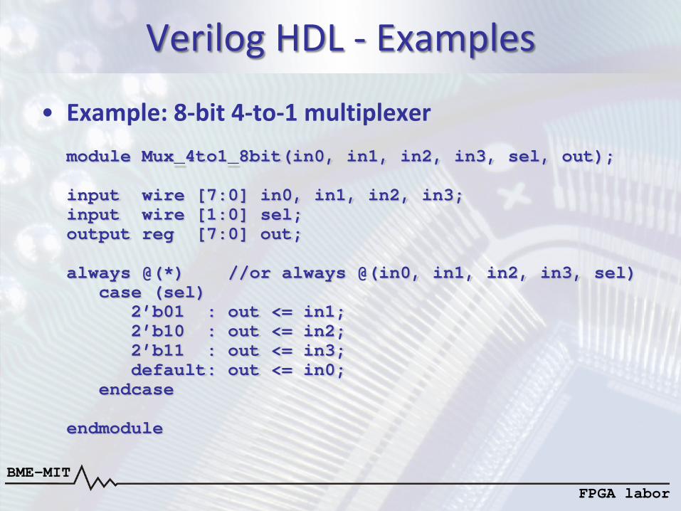
• Example: 8-bit 4-to-1 multiplexer module Mux_4to1_8bit(in0, in1, in2, in3, sel, out); input wire [7:0] in0, in1, in2, in3; input wire [1:0] sel; output reg [7:0] out; always @(*) //or always @(in0, in1, in2, in3, sel) case (sel) 2’b01 : out <= in1; 2’b10 : out <= in2; 2’b11 : out <= in3; default: out <= in0; endcase endmodule