Embed Size (px)
Citation preview
BRITISH STANDARD BS EN
........... 285:1997
Sterilization — Steam sterilizers — Large
sterilizers
The European Standard EN 285: 1996 has the status of a British Standard

Committees responsible for this British Standard
The preparation of this British Standard was entrusted to Technical Committee LBF35, Sterilizers, autoclaves and disinfectors, upon which the following bodies were represented:
ABHI Special Interest Section (Sterilizers and Disinfectors)
Association of British Healthcare Industries
Association of Clinical Pathologists
British Dental Trade Association
Central Sterilising Club
Department of Health
Health and Safety Executive
Infection Control Nurses Association
Institute of Healthcare Engineering and Estate Management
Institute of Sterile Services Management
Medical Sterile Products Association
Public Health Laboratory Service
Royal College of Pathologists
Royal Pharmaceutical Society of Great Britain
Society for General Microbiology

Contents
Page
Committees responsible Inside front cover
National foreword ____________________________________________ ii
Foreword 2
Text of EN 285 _ _____________________________________________ 3 This British Standard, having been prepared under the direction of the Sector Board for Materials and Chemicals, was published
under the authority of the Standards Board and comes into effect on 15 September 1997 © BSI1997 The following BSI references relate to the work on this standard: Committee reference LBI/35 Draft for comment 92/58124 DC ISBN 0 580 27635 X

National foreword
This British Standard has been prepared by Technical Committee LBF35, and is the English language version of EN 285 : 1996 Sterilization — Steam sterilizer's — Large stettiizers, published by the European Committee for Standardization (CEN). It supersedes BS 3970: Part 3 : 1990, which is withdrawn. It also supersedes the current provisions of BS 3970: Part 1: 1990, which is subject to amendment
Steam sterilizers falling within the scope of this standard are considered to be medical devices under Directive 93/42/EEC and compliance with the requirements of the standard is a means of ensuring that particular essential requirements of the Directive are met (see annex ZA of this standard).
Attention is drawn to United Kingdom statutory requirements pertaining to sterilizers and their use. Attention is also drawn to the guidance contained within Health Technical Memorandum (HTM) 2010, published by the Department of Health.
ISO 228-1 BS 2779 : 1986 Specification for pipe threads for tubes and fittings wJiere pressure-tight joints are not made on the threads (metric dimensions) EN ISO 3746 : 1995 BS EN ISO 3746 : 1996 Acoustics. Determination of sound power levels of noise sources using sound pressure. Survey method using an enveloping measurement
surface over a reflecting plane ISO 4017 BS EN 24017 : 1992 Hexagon head screws. Product grades A andB
Compliance with a British Standard does not of itself confer immunity
from legal obligations.
Cross-references Publication referred to Corresponding British Standard BS EN 10088 Stainless steels
EN 10088-1 BS EN 10088-1: 1995 List of stainless steels
EN 10088-2 BS EN 10088-2 : 1995 Technical delivery conditions for sheet/plate and strip for general
purposes
EN 10088-3 BS EN 10088-3 : 1995 Technical delivery conditions for semi-finished products, bars, rods
and sections for general purposes
BS EN 50081 Electromagnetic compatibility.
Generic emission standard
EN 50081-1 BS EN 50081-1: 1992 Residential, commercial and light industry
EN 50081-2 BS EN 50081-2 : 1994 Industrial environment
BS EN 50082 Electromagnetic compatibility.
Genetic immunity standard
EN 50082-1 BS EN 50082-1: 1992 Residential, commercial and light industry
EN 50082-2 BS EN 50082-2 : 1995 Industrial environment
BS EN 60204 Safety of machinery.
Electrical equipment of machines
EN 60204-1: 1992 BS EN 60204-1: 1993 Specification for general requirements
BS EN 60584 Thermocouples
EN 60584-2 : 1993 BS EN 60584-2 : 1993 Tolerances
EN 60651:1994 BS EN 60651: 1994 Specification for sound level meters
EN 60751:1995 BS EN 60751: 1996 Industrial platinum resistance thermometer sensors
EN 60804 :1994 BS EN 60804 : 1994 Specification far integrating-av^aging sound level meters
BS EN 61010 Safety requirements for electrial equipment for measurement, control and laboratory
use
EN 61010-1 BS EN 61010-1: 1993 General requirements
EN 61010-2-041 BS EN 61010-2-041: 1997 Particular requirements for autoclaves using steam for the
treatment of medical materials, and for laboratory processes
EUROPEAN STANDARD EN 285
NORME EUROPEENNE
EUROPAISCHE NORM October 1996
ICS 11.080
Descriptors: Sterilization, medical equipment, sterilizers, water vapour, equipment specifications, locking devices, doors, fittings, measuring instruments, indicating instruments, specifications
English version
Sterilization — Steam sterilizers — Laige sterilizers
Sterilisation - Sterilisateurs a la vapeur d'eau — Sterilisation — Dampf-Sterilisatoren —
Grands Sterilisateurs Grofi-Sterilisatoren
This European Standard was approved by CEN on 1996-09-14. CEN members are bound to comply with the CEN/CENELEC Internal Regulations which stipulate the conditions for giving this European Standard the status of a national standard without any alteration.
Up-to-date lists and bibliographical references concerning such national standards may be obtained on application to the Central Secretariat or to any CEN member.
This European Standard exists in three official versions (English, French, German). A version in any other language made by translation under the responsibility of a CEN member into its own language and notified to the Central Secretariat has the same status as the official versions.
CEN members are the national standards bodies of Austria, Belgium, Denmark, Finland, France, Germany, Greece, Iceland, Ireland, Italy, Luxembourg, Netherlands, Norway, Portugal, Spain, Sweden, Switzerland and United Kingdom.
European Committee for Standardization Comite Europeen de Normalisation Europaisches Komitee fur
Normung
Central Secretariat: rue de Stassart 36, B-1050 Brussels
Foreword
This European Standard has been prepared by Technical Committee CEN/TC 102, Sterilizers for medical purposes, Nthe secretariat of which is held by DIN.
This European Standard shall be given the status of a national standard, either by publication of an identical text or by endorsement, at the latest by April 1997, and conflicting national standards shall be withdrawn at the latest by April 1997.
This European Standard has been prepared under a mandate given to CEN by the European Commission and the European Free Trade Association, and supports essential requirements of EU Directive(s). For the relationship with EU Directive(s) see informative annex ZA, which is an integral part of this standard.
This European Standard specifies requirements and the relevant tests for large steam sterilizers. Specifications of requirements and tests for small steam sterilizers as well as for sterilizers using other sterilants than steam are in preparation by CEN/TC 102.
This European Standard does not specify requirements for the validation and routine control of sterilization by moist heat. A European Standard specifying requirements for the validation and routine control of sterilization by moist heat was prepared by CEN/TC 204, Sterilization of medical devices, see EN 554 Sterilization of medical devices — Validation and routine control of sterilization by moist heat. According to the CEN/CENELEC Internal Regulations, the national standards organizations of the following countries are bound to implement this European Standard: Austria, Belgium, Denmark, Finland, France, Germany, Greece, Iceland, Ireland, Italy, Luxembourg, Netherlands, Norway, Portugal, Spain, Sweden, Switzerland and the United Kingdom.
Contents
Page
Foreword 2
1 Scope 3
2 Normative references 3
3 Definitions 4
4 Mechanical components 5
5 Process components 7
6 Instrumentation - Indication and
registration devices 8
7 Control sytems 13
8 Performance requirements 14
9 Sound power 15
10 Rate of pressure change 15
11 Safety 15
12 Marking 15
13 Service and local environment 15
14 Installation checks 17
15 Categories of tests 17
16 Test programmes 17
17 Microbiological tests 19
18 Thermometric tests 20
19 Bowie and Dick test 23
20 Air leakage test 23
21 Air detector tests 24
22 Load dryness tests 25
23 Sound power test 27
24 Steam quality tests 28
25 Dynamic sterilizer chamber pressure
test 35
26 Test apparatus, equipment and
material 35
27 Documentation 39
28 Information 39
Annexes
A (informative) Recommended materials 40
B (informative) Suggested maximum
values of steam contaminants 42
C (informative) Bibliography 43
ZA (informative) Clauses of this European Standard addressing essential requirements or other provisions of EU Directives 44
1 Scope
1.1 This European Standard specifies requirements and the relevant tests for large steam sterilizers primarily used in health care for the sterilization of one or more sterilization modules for wrapped goods (instruments etc. and porous loads).
Large steam sterilizers can also be used during the commercial production of medical devices. NOTE. Sterilizers conforming to this standard can offer a single automatic sterilization cycle or a number of selectable automatic sterilization cycles, e.g. with different operating temperatures (see 28.3b)].
1.2 This European Standard is not applicable to small steam sterilizers or to steam sterilizers used for the sterilization of pharmaceutical products in containers. NOTE. The use of sterilizers for unwrapped instruments and utensils for immediate use in aseptic areas and for fluid-sterilizers will be the subject of a separate standard.
1.3 This European Standard does not describe a quality assurance system for the control of all stages of the manufacture of the sterilizer. NOTE. Attention is drawn to the standards for quality systems (see EN ISO 9001, EN ISO 9002, EN ISO 90044 and EN 46001 and EN 46002).
2 Normative references
This European Standard incorporates, by dated or undated reference, provisions from other publications. These normative references are cited at the appropriate places in the text and the publications are listed hereafter. For dated references, subsequent amendments to or revisions of any of these publications apply to this European Standard only when incorporated in it by amendment or revision. For undated references, the latest edition of the publication referred to applies.
prEN 866-1 Biological systems for testing sterilizers — Part 1: General requirements
prEN 866-3 Biological systems for testing sterilizers — Part 3: Particular systems for use in steam sterilizers
prEN 867-3 Non-biological systems for use in sterilizers — Part 3: Specification for class B indicators for use in the Bowie and Dick test
prEN 868-5 Packaging materials for sterilization of wrapped goods — Part 5: Heat scalable pouches and reel material of paper and plastic construction — Requirements and tests
EN 10088-1 Stainless steels — Part 1: List of stainless steels
EN 10088-2 Stainless steels — Part 2: Technical delivery conditions for sheet/plate and strip for general purposes
EN 10088-3 Stainless steels — Part 3: Technical delivery conditions for semi-finished products, bars, rods and sections fen" general purposes
EN 50081-1 Electromagnetic compatibility — Generic emission standard — Part 1: Residential, commercial and light industry
EN 50081-2 Electromagnetic compatibility — Generic emission standard — PaH 2: Industrial environment
EN 50082-1 Electromagnetic compatibility — Generic immunity standard — Part 1: Residential, commercial and light industry
EN 50082-2 Electromagnetic compatibility — Generic immunity standard — Part 2: Industrial environment
EN 60204-1: Safety of jnachinery — Electrical, 1992 equipment of machines —
Part 1: General requirements (IEC 204-1: 1992, modified)
EN 60584-2: Tliermocouples — Part 2: Tolerances
1993 (TEC 584-2 : 1982 + Al: 1989)
EN 60651:1994 Sound level meters
(IEC 651: 1979 + Al: 1993)
EN 60751: 1995 Industrial platinum resistance thei^nometej" sensors (IEC 751: 1983 + Al : 1986)
EN 60804:1994 Integrating-averaging sound level meters (IEC 804: 1985 + Al : 1989) EN 61010-1 Safety requirements for electrical equipment for measurement, control and laboratory use — Part 1: General requirements (IEC 1010-1: 1990 + Al : 1992, modified) EN 61010-2-041 Safety requirements for electrical equipment for measurement, control and laboratory use - Part 2-041: Particular requirements fen- autoclaves using steam for the treatment of medical materials, and for laboratory processes (IEC 1010-2-041:1996) IEC 38 IEC standard voltages
ISO 228-1 Pipe flireads where pressure-tight joints are not made on the threads — Part 1: Dimensions, tolerances and designation
EN ISO 3746: Acoustics — Determination of sound 1995 power levels of noise sources using
sound pressure — Survey method using an enveloping measurement surface over a reflecting plane (ISO 3746: 1995)
ISO 4017 Hexagon head screws — Product grades A and B
3 Definitions
For the purposes of this standard the definitions of
EN 764 apply, together with the following.
NOTE. Other definitions relevant to validation are given in EN 554.
3.1 active drain
Drain which is situated at the lowest part of the sterilizer chamber to control the discharge of air/non-condensable gases or air and condensate from the sterilizer chamber.
3.2 air removal
Removal of air from the sterilizer chamber and sterilizer load sufficient to facilitate steam penetration.
3.3 automatic controller
Device that, in response to pre-determined cycle variables, operates the sterilizer sequentially through the required stages of the cycle(s).
3.4 biological indicator
An inoculated carrier contained within its primary pack ready for use (prEN 866-1).
3.5 calibration
The set of operations that establish, under specified conditions, the relationship between values of a quantity indicated by a measuring instrument or measuring system, or values represented by a material measure or a reference material, and the corresponding values realized by standards.
3.6 chamber depth
Depth of the sterilizer chamber which is available for the sterilizer load.
3.7 chamber height
Height of the sterilizer chamber which is available for the sterilizer load.
3.8 chamber width
Width of the sterilizer chamber which is available for the sterilizer load.
3.9 chamber temperature
Lowest temperature prevailing in the sterilizer chamber (EN 554).
3.10 cycle complete
Indication that the sterilization cycle has been satisfactorily completed and that the sterilized load is ready for removal from the sterilizer chamber.
3.11 dedicated steam supply
Supply of steam produced for a sterilizer, or group of sterilizers, by a dedicated generator.
3.12 door
Lid or similar device provided as a means of closing and sealing the sterilizer chamber.
3.13 double ended sterilizer
Sterilizer in which there is a door at each end of the sterilizer chamber.
3.14 dry saturated steam
Steam with a temperature and pressure corresponding to the vaporization curve of water. NOTE. This is an ideal condition which can deviate towards either superheated steam or to wet steam. This deviation is quantified by the determination of the Dryness Value.
3.15 equilibration time
Period which elapses between the attainment of the sterilization temperature in the sterilizer chamber and the attainment of the sterilization temperature at all points within the load (EN 554).
3.16 fail safe
Attribute of sterilizer design, component or its associated services that minimizes a possible safety hazard.
3.17 fault
Recognition by the automatic controller that the pre-set cycle variables for the sterilization cycle have not been
attained.
3.18 holding time
Period for which the temperature of all points within the sterilizer is held within the sterilization temperature band.
NOTE. The holding time follows immediately after the equilibration time. The extent of the holding time is related to the sterilization temperature.
3.19 inoculated carrier
A carrier on which a defined number of test organisms has been deposited (prEN 866-1).
3.20 installation test
Series of checks and tests performed after installation of the sterilizer in the place of use (EN 554).
3.21 loading door
Door in a double-ended sterilizer through which the sterilizer load is put into the sterilizer chamber prior to sterilization.
3.22 medical device
The definition given in EN 46001 applies.
3.23 non-condensable gas
Air and other gas which will not condense under the conditions of steam sterilization.
3.24 plateau period
Equilibration time plus the holding time.
3.25 pressure vessel
A vessel describing the sterilizer chamber, jacket (if fitted), door(s) and components that are in permanent connection with the sterilizer chamber.
3.26 reference measurement point
Reference point for which documented evidence is available to demonstrate that it has a known relationship to the temperature of the coolest part of the sterilizer chamber.
3.27 reference standard
Standard, generally having the highest metrological quality available at a given location or in a given organization, from which measurements made there are derived.
3.28 safety hazard
Potentially detrimental effect on persons or the surroundings arising directly from either the sterilizer or its load.
3.29 small steam sterilizer
Steam sterilizer which is unable to accommodate a sterilization module.
3.30 sterile
Condition of a medical device that is free from viable micro-organisms (EN 556).
3.31 sterilization
Process undertaken to render a sterilizer load sterile.
3.32 sterilization cycle
Automatic sequence of operating stages performed in a sterilizer for the purpose of sterilization (EN 554).
3.33 sterilization module
Rectangular parallelepiped of the dimensions 300 mm X 300 mm X 600 mm used for the puiposes of sterilization.
3.34 sterilization temperature
Minimum temperature of the sterilization temperature band (EN 554).
3.35 sterilization temperature band
Range of temperatures, expressed as the sterilization temperature and the maximum allowable temperature which may prevail throughout the load during the holding time (EN 554). NOTE. These temperatures are usually stated in whole degrees Celsius.
3.36 sterilizer
Apparatus designed to achieve sterilization.
3.37 sterilizer chamber
That part of the sterilizer which receives the sterilizer load (EN 554).
3.38 sterilizer load
Goods that are to be sterilized simultaneously in the same sterilizer chamber (EN 554).
3.39 superheated steam
Steam whose temperature, at any given pressure, is higher than that indicated by the vaporization curve of water.
3.40 test organism
Mcro-organisms used for the manufacture of inoculated carriers (prEN 866-1).
3.41 type test
Series of tests to establish the working data for a sterilizer type.
3.42 unloading door
Door in a double-ended sterilizer through which the sterilized load is removed from the sterilizer chamber after a sterilization cycle.
3.43 usable space
Space inside the sterilizer chamber which is not restricted by fixed parts and which is consequently available to accept the sterilizer load. NOTE. The usable space is expressed in terms of chamber height, chamber width and chamber depth.
3.44 works test
Series of tests performed at the manufacturer's works to demonstrate compliance of each sterilizer with its specification.
4 Mechanical components
4.1 Dimensions
The usable space within the sterilizer chamber shall accommodate one or more sterilization modules.
4.2 Materials
Materials in contact with steam shall:
- resist attack from steam and condensate;
- not cause deterioration of the quality of the steam;
NOTE 1. Guidance is given in annex B.
- not release any substances known to be toxic in such quantities as could create a health hazard.
NOTE 2. Because of the different types of sterilizers and the large number of uses, it is not possible to specify detailed requirements for materials for specific applications. The purchaser should provide the manufacturer with information about the goods to be sterilized.
NOTE 3. Advice on the various combinations of materials is given in annex A.
4.3 Pressure equipment
4.3.1 General
4.3.1.1 A Council Directive on the approximation of the laws of the member states concerning pressure equipment (see 93/C246/01) and corresponding European Standards are in preparation (CEN/TC 54 and CEN/TC 269). Until European Standards on pressure equipment are published, the pressure equipment should comply with national regulations and standards applying in the country of intended use.
4.3.1.2 Sterilizers shall be provided with one or two doors.
4.3.1.3 The door seal shall be a replaceable component.
It shall be possible to inspect and clean the surface of the door seal which comes into contact with the sealing faces without the need to dismantle the door assembly.
4.3.1.4 After closing the sterilizer door, it shall be possible to open it without having first to initiate a sterilization cycle.
4.3.1.5 Except in the case of a fault, it shall not be possible to open a sterilizer door(s) during a sterilization cycle.
4.3.2 Double-ended sterilizers
4.3.2.1 Except for maintenance purposes, it shall not be possible for more than one door to be open at one time.
4.3.2.2 It shall not be possible to open the unloading door until a 'cycle complete' indication is obtained.
4.3.2.3 It shall not be possible to open the unloading door if a Bowie and Dick test has been carried out
4.3.2.4 The control used to start the sterilization cycle shall be located at the loading side of the sterilizer.
4.3.3 Test connections
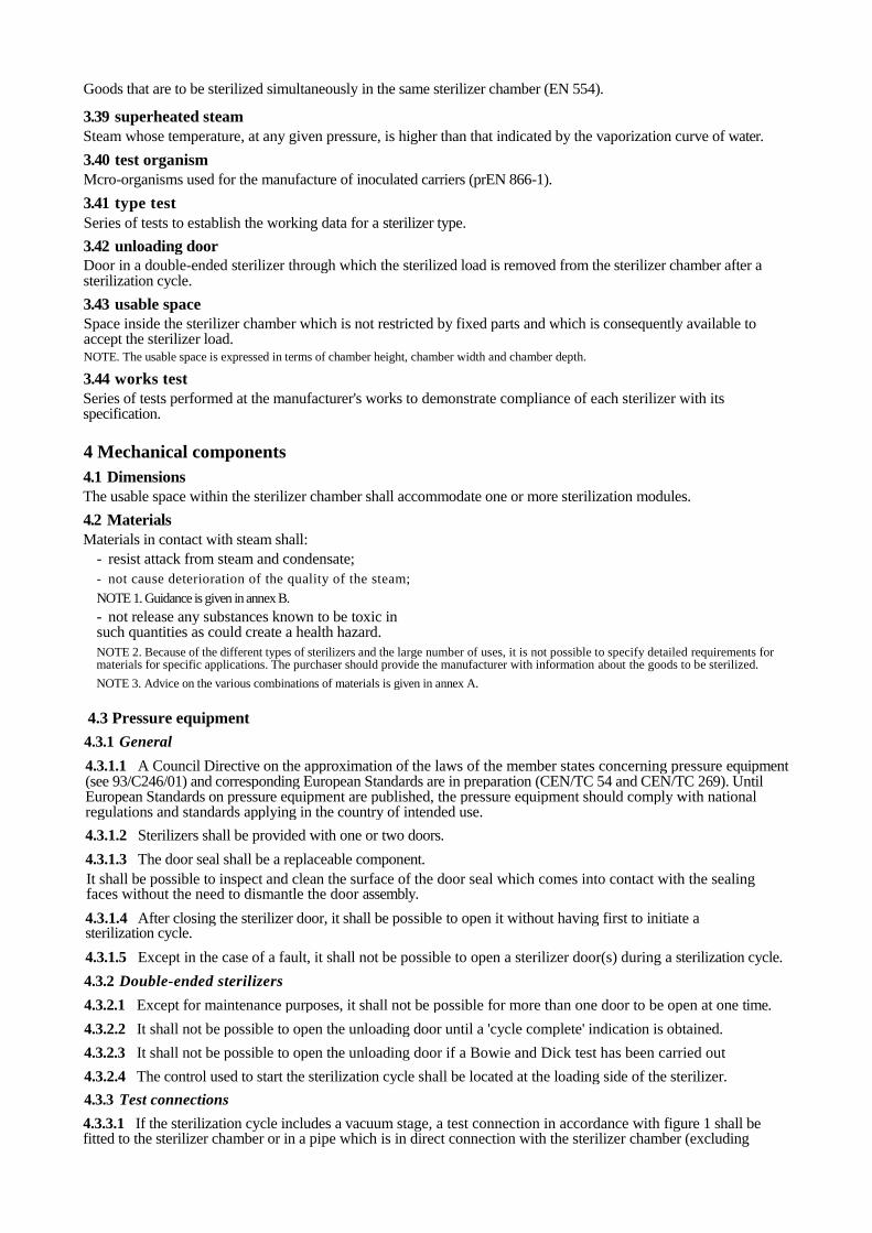
4.3.3.1 If the sterilization cycle includes a vacuum stage, a test connection in accordance with figure 1 shall be fitted to the sterilizer chamber or in a pipe which is in direct connection with the sterilizer chamber (excluding
vacuum line). The test connection which is used for the connection of a test instrument shall be provided with a standard cap, marked VT (vacuum test) and sealed with either an O-ring-seal or a flat seal.
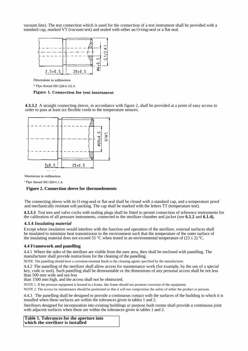
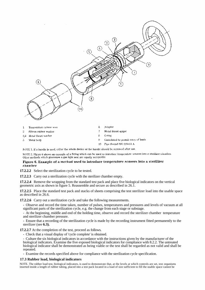
4.3.3.2 A straight connecting sleeve, in accordance with figure 2, shall be provided at a point of easy access in order to pass at least six flexible cords to the temperature sensors.
Figure 2. Connection sleeve for thermoelements
The connecting sleeve with its O-ring-seal or flat seal shall be closed with a standard cap, and a temperature proof and mechanically resistant soft packing. The cap shall be marked with the letters TT (temperature test).
4.3.3.3 Test tees and valve cocks with sealing plugs shall be fitted to permit connection of reference instruments for the calibration of all pressure instruments, connected to the sterilizer chamber and jacket (see 6.1.2 and 6.1.4).
4.3.4 Insulating material
Except where insulation would interfere with the function and operation of the sterilizer, external surfaces shall be insulated to minimize heat transmission to the environment such that the temperature of the outer surface of the insulating material does not exceed 55 °C when tested in an environmental temperature of (23 ± 2) °C.
4.4 Framework and panelling
4.4.1 Where the sides of the sterilizer are visible from the user area, they shall be enclosed with panelling. The manufacturer shall provide instructions for the cleaning of the panelling. NOTE. The panelling should have a corrosion-resistant finish to the cleaning agents specified by the manufacturer.
4.4.2 The panelling of the sterilizer shall allow access for maintenance work (for example, by the use of a special key, code or tool). Such panelling shall be demountable or the dimensions of any personal access shall be not less than 500 mm wide and not less than 1500 mm high, and the access shall not be obstructed. NOTE 1. If the pressure equipment is housed in a frame, this frame should not promote corrosion of the equipment. NOTE 2. The access for maintenance should be positioned so that it will not compromise the safety of either the product or persons.
4.4.3 The panelling shall be designed to provide a continuous contact with the surfaces of the building in which it is installed when these surfaces are within the tolerances given in tables 1 and 2.
Sterilizers designed for incorporation into existing buildings or purpose built rooms shall provide a continuous joint with adjacent surfaces when these are within the tolerances given in tables 1 and 2.
Table 1. Tolerances for the aperture into which the sterilizer is installed
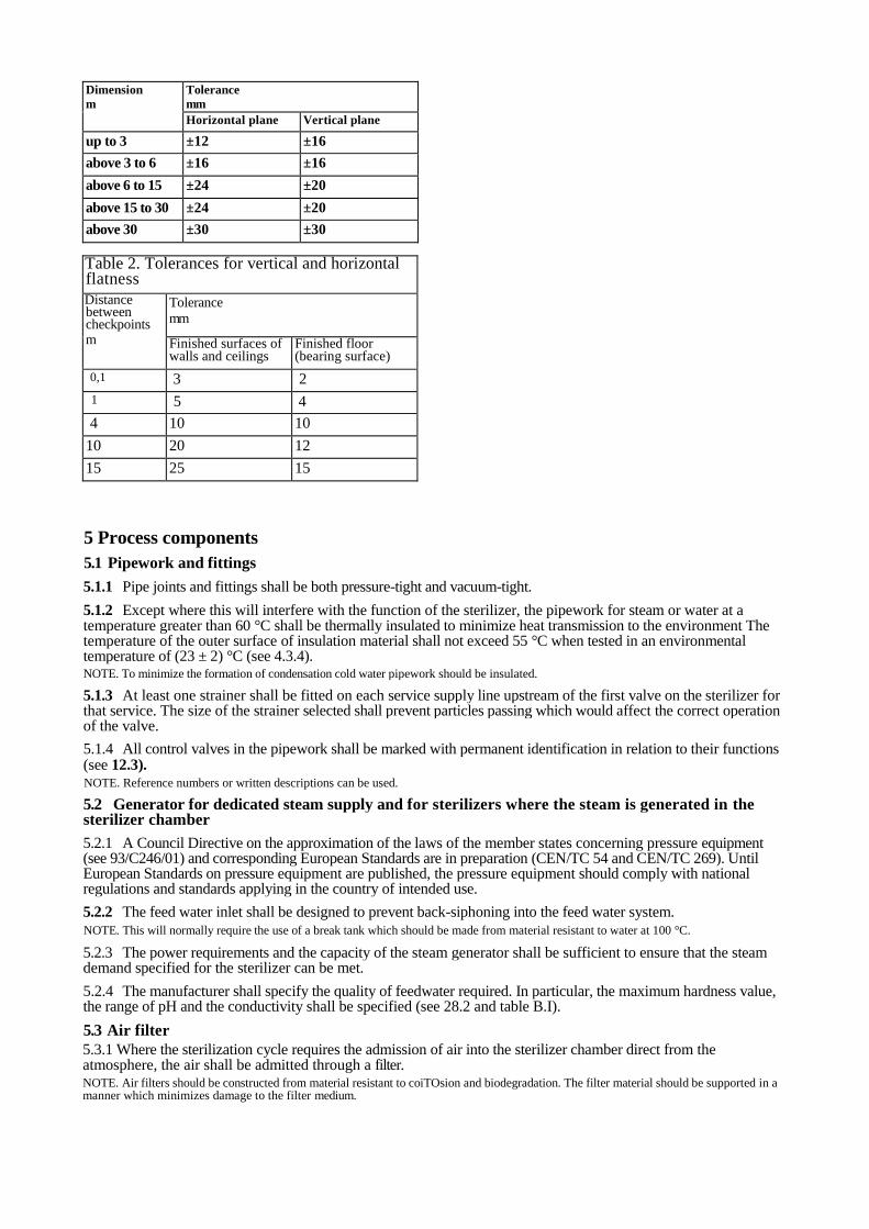
Dimension m
Tolerance mm Horizontal plane Vertical plane
up to 3 ±12 ±16
above 3 to 6 ±16 ±16
above 6 to 15 ±24 ±20
above 15 to 30 ±24 ±20
above 30 ±30 ±30
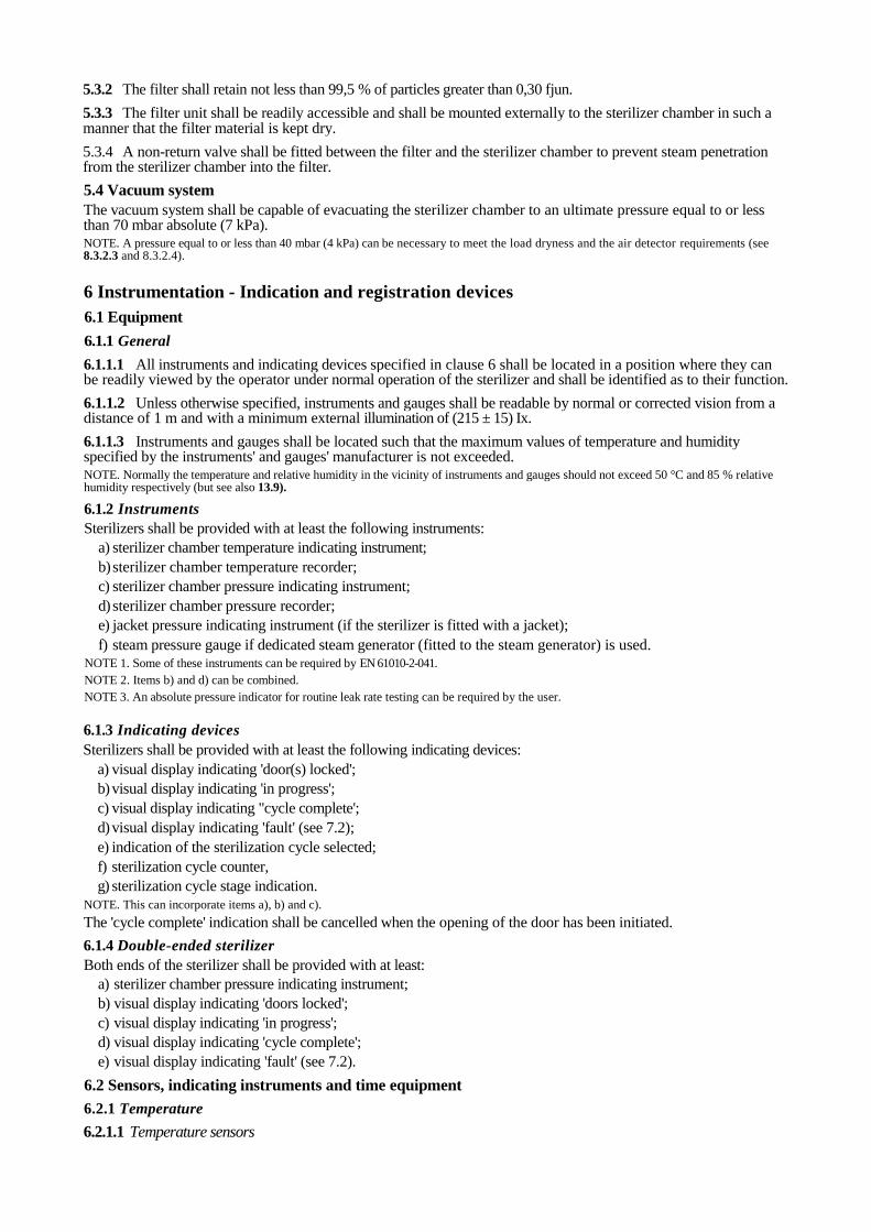
Table 2. Tolerances for vertical and horizontal flatness
Distance between checkpoints m
Tolerance mm
Finished surfaces of walls and ceilings
Finished floor (bearing surface)
0,1 3 2
1 5 4
4 10 10
10 20 12
15 25 15
5 Process components
5.1 Pipework and fittings
5.1.1 Pipe joints and fittings shall be both pressure-tight and vacuum-tight.
5.1.2 Except where this will interfere with the function of the sterilizer, the pipework for steam or water at a temperature greater than 60 °C shall be thermally insulated to minimize heat transmission to the environment The temperature of the outer surface of insulation material shall not exceed 55 °C when tested in an environmental temperature of (23 ± 2) °C (see 4.3.4). NOTE. To minimize the formation of condensation cold water pipework should be insulated.
5.1.3 At least one strainer shall be fitted on each service supply line upstream of the first valve on the sterilizer for that service. The size of the strainer selected shall prevent particles passing which would affect the correct operation of the valve.
5.1.4 All control valves in the pipework shall be marked with permanent identification in relation to their functions (see 12.3). NOTE. Reference numbers or written descriptions can be used.
5.2 Generator for dedicated steam supply and for sterilizers where the steam is generated in the sterilizer chamber
5.2.1 A Council Directive on the approximation of the laws of the member states concerning pressure equipment (see 93/C246/01) and corresponding European Standards are in preparation (CEN/TC 54 and CEN/TC 269). Until European Standards on pressure equipment are published, the pressure equipment should comply with national regulations and standards applying in the country of intended use.
5.2.2 The feed water inlet shall be designed to prevent back-siphoning into the feed water system.
NOTE. This will normally require the use of a break tank which should be made from material resistant to water at 100 °C.
5.2.3 The power requirements and the capacity of the steam generator shall be sufficient to ensure that the steam demand specified for the sterilizer can be met.
5.2.4 The manufacturer shall specify the quality of feedwater required. In particular, the maximum hardness value, the range of pH and the conductivity shall be specified (see 28.2 and table B.I).
5.3 Air filter
5.3.1 Where the sterilization cycle requires the admission of air into the sterilizer chamber direct from the atmosphere, the air shall be admitted through a filter. NOTE. Air filters should be constructed from material resistant to coiTOsion and biodegradation. The filter material should be supported in a manner which minimizes damage to the filter medium.
5.3.2 The filter shall retain not less than 99,5 % of particles greater than 0,30 fjun.
5.3.3 The filter unit shall be readily accessible and shall be mounted externally to the sterilizer chamber in such a manner that the filter material is kept dry.
5.3.4 A non-return valve shall be fitted between the filter and the sterilizer chamber to prevent steam penetration from the sterilizer chamber into the filter.
5.4 Vacuum system
The vacuum system shall be capable of evacuating the sterilizer chamber to an ultimate pressure equal to or less than 70 mbar absolute (7 kPa). NOTE. A pressure equal to or less than 40 mbar (4 kPa) can be necessary to meet the load dryness and the air detector requirements (see 8.3.2.3 and 8.3.2.4).
6 Instrumentation - Indication and registration devices
6.1 Equipment
6.1.1 General
6.1.1.1 All instruments and indicating devices specified in clause 6 shall be located in a position where they can be readily viewed by the operator under normal operation of the sterilizer and shall be identified as to their function.
6.1.1.2 Unless otherwise specified, instruments and gauges shall be readable by normal or corrected vision from a distance of 1 m and with a minimum external illumination of (215 ± 15) Ix.
6.1.1.3 Instruments and gauges shall be located such that the maximum values of temperature and humidity specified by the instruments' and gauges' manufacturer is not exceeded. NOTE. Normally the temperature and relative humidity in the vicinity of instruments and gauges should not exceed 50 °C and 85 % relative humidity respectively (but see also 13.9).
6.1.2 Instruments
Sterilizers shall be provided with at least the following instruments:
a) sterilizer chamber temperature indicating instrument;
b) sterilizer chamber temperature recorder;
c) sterilizer chamber pressure indicating instrument;
d) sterilizer chamber pressure recorder;
e) jacket pressure indicating instrument (if the sterilizer is fitted with a jacket);
f) steam pressure gauge if dedicated steam generator (fitted to the steam generator) is used. NOTE 1. Some of these instruments can be required by EN 61010-2-041.
NOTE 2. Items b) and d) can be combined.
NOTE 3. An absolute pressure indicator for routine leak rate testing can be required by the user.
6.1.3 Indicating devices
Sterilizers shall be provided with at least the following indicating devices:
a) visual display indicating 'door(s) locked';
b) visual display indicating 'in progress';
c) visual display indicating "cycle complete';
d) visual display indicating 'fault' (see 7.2);
e) indication of the sterilization cycle selected;
f) sterilization cycle counter,
g) sterilization cycle stage indication.
NOTE. This can incorporate items a), b) and c).
The 'cycle complete' indication shall be cancelled when the opening of the door has been initiated.
6.1.4 Double-ended sterilizer
Both ends of the sterilizer shall be provided with at least:
a) sterilizer chamber pressure indicating instrument;
b) visual display indicating 'doors locked';
c) visual display indicating 'in progress';
d) visual display indicating 'cycle complete';
e) visual display indicating 'fault' (see 7.2).
6.2 Sensors, indicating instruments and time equipment
6.2.1 Temperature
6.2.1.1 Temperature sensors
Temperature sensors shall be either platinum resistance types complying with Class A of EN 60751:1995 or thermocouples complying with one of the tables specified in tolerance class 1 of EN 60584-2:1993. NOTE. Other systems of demonstrated equivalence can be used.
The temperature sensor shall have a response time TO < 5 s when tested in water.
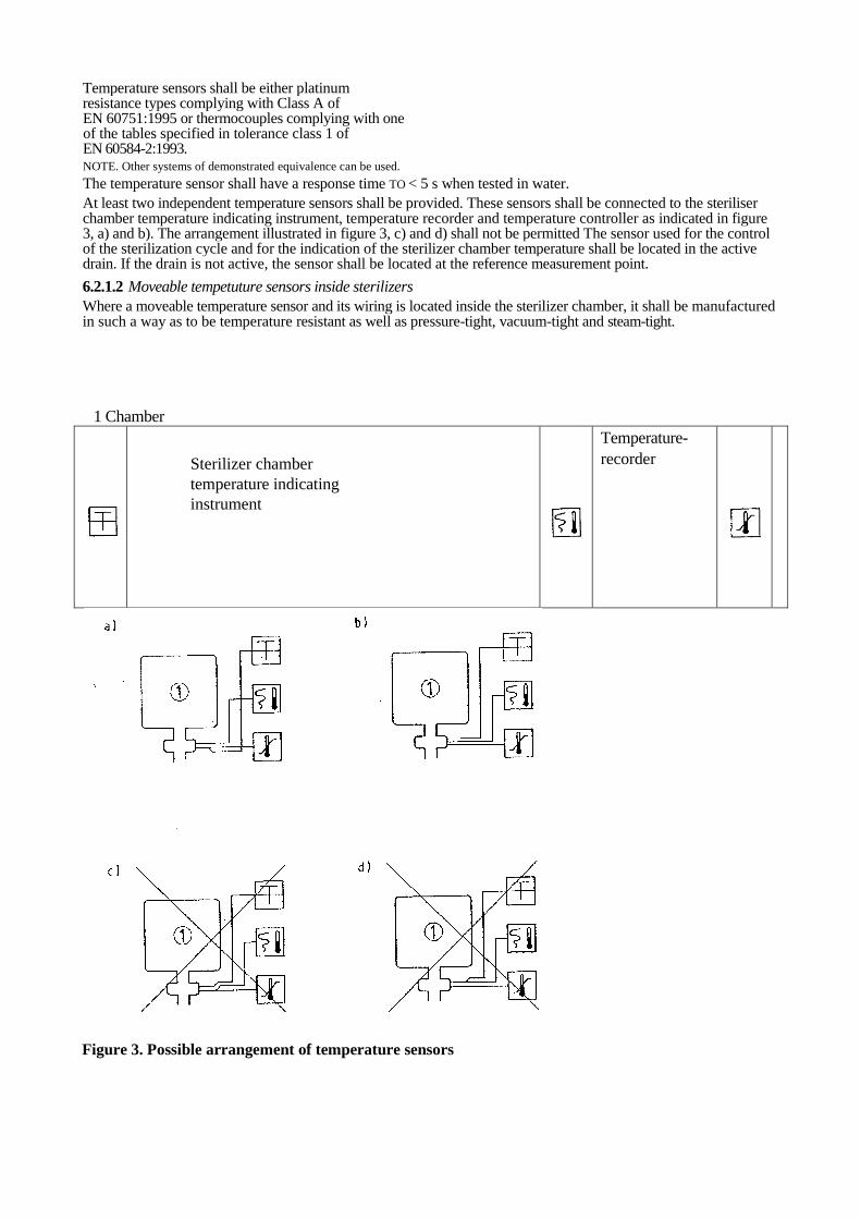
At least two independent temperature sensors shall be provided. These sensors shall be connected to the steriliser chamber temperature indicating instrument, temperature recorder and temperature controller as indicated in figure 3, a) and b). The arrangement illustrated in figure 3, c) and d) shall not be permitted The sensor used for the control of the sterilization cycle and for the indication of the sterilizer chamber temperature shall be located in the active drain. If the drain is not active, the sensor shall be located at the reference measurement point.
6.2.1.2 Moveable tempetuture sensors inside sterilizers
Where a moveable temperature sensor and its wiring is located inside the sterilizer chamber, it shall be manufactured in such a way as to be temperature resistant as well as pressure-tight, vacuum-tight and steam-tight.
1 Chamber
Sterilizer chamber
temperature indicating
instrument
Temperature-
recorder
Figure 3. Possible arrangement of temperature sensors
Control of plateau period by temperature
6.2.1.3 Sterilizer chamber temperature indicating instrument
The sterilizer chamber temperature indicating instrument shall:
a) be either digital or analogue;
b) be graduated in degrees Celsius;
c) have a scale which includes the range 50 °C to
150 °C;
d) have an accuracy of at least — 1% over the scale range 50 °C to 150 °C;
e) for analogue instruments, be graduated in divisions not greater than 2 °C;
f) for digital instruments, have a resolution of at least 0,1 °C;
g) be adjusted to an accuracy of at least ± 0,5 °C at the sterilization temperature;
h) when used for a control function, have broken sensor protection to fail safe in its control function application (see 7.1);
j) have an ambient temperature error compensation not exceeding 0,04 K/K;
k) have means to adjust in situ by the use of a special key, code or tool without dismantling the instrument
6.2.2 Pressure
6.2.2.1 Sterilizer chamber pressure itidicating instrument
The sterilizer chamber pressure indicating instrument shall:
a) be either digital or analogue;
b) be graduated in bars or Mlopascals;
c) have a scale which includes the range -1 barn to 3 bar or 0 kPa to 400 kPa with a zero reading at ambient pressure or absolute vacuum respectively;
d) have an accuracy of at least ± 1,6 % over the scale range -1 bar to 3 bar (0 kPa to 400 kPa);
e) for analogue instruments, be graduated in divisions not greater than 0,2 bar (20 kPa);
f) for digital instruments, have a resolution of at least 0,01 bar (1 kPa);
g) be adjusted to an accuracy of at least ± 0,05 bar (± 5 kPa) at the operating pressure;
h) when used for a control function, have broken sensor protection to fail safe in its control function application (see 7.1);
j) have an ambient temperature error compensation not exceeding 0,04 %/K over the scale range -1 bar to 3 bar (0 kPa to 400 kPa);
k) have means to adjust in situ by the use of a special key, code or tool without dismantling the instrument NOTE. Where digital pressure indicators are used, an additional mechanically actuated indicator can be required to comply with national pressure vessel regulations. Where an analogue instrument is provided only for this purpose, the requirement for adyustment in situ is waived.
6.2.2.2 Absolute pj~essure indicator
Where an absolute pressure indicator is required for leak rate testing and is to be fitted to the sterilizer (see Note 3 of 6.1.2) it shall:
a) be either digital or analogue;
b) be graduated in millibars or Mopascals;
c) have a scale which includes 0 mbar to 160 mbar absolute (0 kPa to 16 kPa);
d) have an accuracy of at least ± 1 % over the scale range 0 mbar to 160 mbar absolute (0 kPa to 16 kPa);
e) be graduated in divisions not greater than 4 mbar (0,4 kPa) and with the scale greater than 1 mbar/mm (0,1 kPa/mm) for analogue instruments;
f) have a resolution of at least 1 mbar (0,1 kPa) for digital instruments;
g) have means to adjust in situ by the use of a special key, code or tool without dismantling the instrument
6.2.3 Time indicating equipment
If time indicators are fitted they shall:
a) be graduated in seconds or minutes;
b) have an accuracy of at least ± 2,5 % for periods up to 5 min and at least ± 1 % for periods above 5 min;
c) have means to adjust in situ by means of a special key, code or tool.
6.3 Recorders and records 6.3.1 General
6.3.1.1 The recorder shall be either analogue or digital.
6.3.1.2 The recorder shall be independent of the automatic controller.
6.3.1.3 Records shall include the limiting values for all cycle variables throughout the sterilization cycle. The printing of data shall be sufficient to ensure that any deviation outside permitted tolerances can be identified
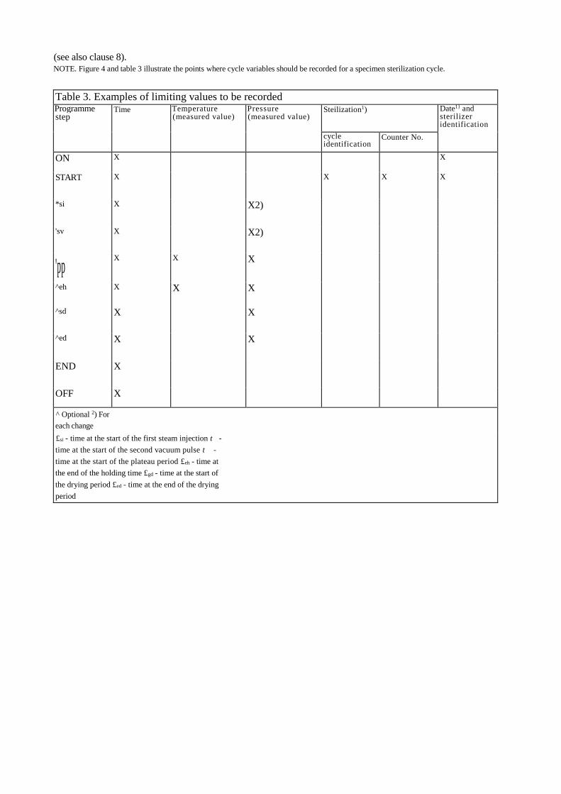
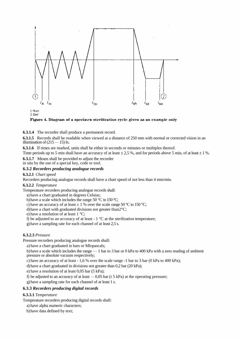
(see also clause 8). NOTE. Figure 4 and table 3 illustrate the points where cycle variables should be recorded for a specimen sterilization cycle.
Table 3. Examples of limiting values to be recorded
Programme step
Time Temperature (measured value)
Pressure (measured value)
Steilization1) Date1} and sterilizer identification
cycle identification
Counter No.
ON X X
START X X X X
*si X X2)
'sv X X2)
'pp
X X X
^eh X X X
^sd X X
^ed X X
END X
OFF X
^ Optional 2) For
each change
£si - time at the start of the first steam injection t -
time at the start of the second vacuum pulse t -
time at the start of the plateau period £eh - time at
the end of the holding time £gd - time at the start of
the drying period £ed - time at the end of the drying
period
6.3.1.4 The recorder shall produce a permanent record.
6.3.1.5 Records shall be readable when viewed at a distance of 250 mm with normal or corrected vision in an illumination of (215 — 15) Ix.
6.3.1.6 If times are marked, units shall be either in seconds or minutes or multiples thereof.
Time periods up to 5 min shall have an accuracy of at least ± 2,5 %, and for periods above 5 min, of at least ± 1 %.
6.3.1.7 Means shall be provided to adjust the recorder in situ by the use of a special key, code or tool.
6.3.2 Recorders producing analogue records
6.3.2.1 Chart speed
Recorders producing analogue records shall have a chart speed of not less than 4 mm/min.
6.3.2.2 Temperature
Temperature recorders producing analogue records shall:
a) have a chart graduated in degrees Celsius; b) have a scale which includes the range 50 °C to 150 °C; c) have an accuracy of at least ± 1 % over the scale range 50 °C to 150 °C;
d) have a chart with graduated divisions not greater than2°C; e) have a resolution of at least 1 °C; f) be adjusted to an accuracy of at least - 1 °C at the sterilization temperature;
g) have a sampling rate for each channel of at least 2,5 s.
6.3.2.3 Pressure
Pressure recorders producing analogue records shall:
a) have a chart graduated in bars or Mlopascals;
b) have a scale which includes the range — 1 bar to 3 bar or 0 kPa to 400 kPa with a zero reading of ambient pressure or absolute vacuum respectively;
c) have an accuracy of at least - 1,6 % over the scale range -1 bar to 3 bar (0 kPa to 400 kPa);
d) have a chart graduated in divisions not greater than 0,2 bar (20 kPa);
e) have a resolution of at least 0,05 bar (5 kPa);
f) be adjusted to an accuracy of at least — 0,05 bar (i 5 kPa) at the operating pressure;
g) have a sampling rate for each channel of at least 1 s.
6.3.3 Recorders producing digital records
6.3.3.1 Temperature
Temperature recorders producing digital records shall:
a) have alpha numeric characters;
b) have data defined by text;
c) have a range which includes 50 °C to 150 °C;
d) have a resolution of at least 0,1 °C;
e) have an accuracy of at least - 1% over the range 50 °C to 150 °C;
f) have a paper width which has a space for a minimum of 15 characters/line;
g) have a sampling rate for each channel of at least 2,5 s.
6.3.3.2 Pressure
Pressure recorders producing digital records shall:
a) have alpha numeric characters;
b) have data defined by text;
c) have a range which includes -1 bar to 3 bar (0 kPa to 400 kPa);
d) have a resolution of at least 0,01 bar (1 kPa);
e) have an accuracy of at least ± 1,6 % over the range -1 bar to 3 bar (0 kPa to 400 kPa);
f) have a paper width which has a space for a minimum of 15 characters/line;
g) have a sampling rate for each channel of at least 1 s.
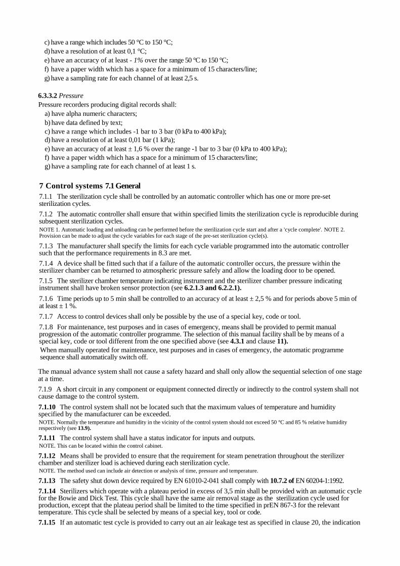
7 Control systems 7.1 General
7.1.1 The sterilization cycle shall be controlled by an automatic controller which has one or more pre-set sterilization cycles.
7.1.2 The automatic controller shall ensure that within specified limits the sterilization cycle is reproducible during subsequent sterilization cycles. NOTE 1. Automatic loading and unloading can be performed before the sterilization cycle start and after a 'cycle complete'. NOTE 2. Provision can be made to adjust the cycle variables for each stage of the pre-set sterilization cycle(s).
7.1.3 The manufacturer shall specify the limits for each cycle variable programmed into the automatic controller such that the performance requirements in 8.3 are met.
7.1.4 A device shall be fitted such that if a failure of the automatic controller occurs, the pressure within the sterilizer chamber can be returned to atmospheric pressure safely and allow the loading door to be opened.
7.1.5 The sterilizer chamber temperature indicating instrument and the sterilizer chamber pressure indicating instrument shall have broken sensor protection (see 6.2.1.3 and 6.2.2.1).
7.1.6 Time periods up to 5 min shall be controlled to an accuracy of at least ± 2,5 % and for periods above 5 min of at least ± 1 %.
7.1.7 Access to control devices shall only be possible by the use of a special key, code or tool.
7.1.8 For maintenance, test purposes and in cases of emergency, means shall be provided to permit manual progression of the automatic controller programme. The selection of this manual facility shall be by means of a special key, code or tool different from the one specified above (see 4.3.1 and clause 11).
When manually operated for maintenance, test purposes and in cases of emergency, the automatic programme sequence shall automatically switch off.
The manual advance system shall not cause a safety hazard and shall only allow the sequential selection of one stage at a time.
7.1.9 A short circuit in any component or equipment connected directly or indirectly to the control system shall not cause damage to the control system.
7.1.10 The control system shall not be located such that the maximum values of temperature and humidity specified by the manufacturer can be exceeded. NOTE. Normally the temperature and humidity in the vicinity of the control system should not exceed 50 °C and 85 % relative humidity respectively (see 13.9).
7.1.11 The control system shall have a status indicator for inputs and outputs. NOTE. This can be located within the control cabinet.
7.1.12 Means shall be provided to ensure that the requirement for steam penetration throughout the sterilizer chamber and sterilizer load is achieved during each sterilization cycle. NOTE. The method used can include air detection or analysis of time, pressure and temperature.
7.1.13 The safety shut down device required by EN 61010-2-041 shall comply with 10.7.2 of EN 60204-1:1992.
7.1.14 Sterilizers which operate with a plateau period in excess of 3,5 min shall be provided with an automatic cycle for the Bowie and Dick Test. This cycle shall have the same air removal stage as the sterilization cycle used for production, except that the plateau period shall be limited to the time specified in prEN 867-3 for the relevant temperature. This cycle shall be selected by means of a special key, tool or code.
7.1.15 If an automatic test cycle is provided to carry out an air leakage test as specified in clause 20, the indication
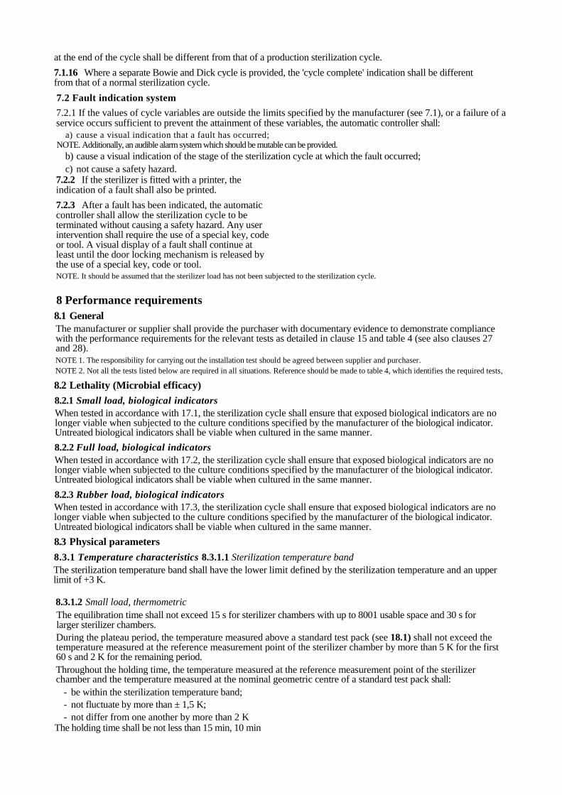
at the end of the cycle shall be different from that of a production sterilization cycle.
7.1.16 Where a separate Bowie and Dick cycle is provided, the 'cycle complete' indication shall be different from that of a normal sterilization cycle.
7.2 Fault indication system
7.2.1 If the values of cycle variables are outside the limits specified by the manufacturer (see 7.1), or a failure of a service occurs sufficient to prevent the attainment of these variables, the automatic controller shall:
a) cause a visual indication that a fault has occurred; NOTE. Additionally, an audible alarm system which should be mutable can be provided.
b) cause a visual indication of the stage of the sterilization cycle at which the fault occurred;
c) not cause a safety hazard. 7.2.2 If the sterilizer is fitted with a printer, the indication of a fault shall also be printed.
7.2.3 After a fault has been indicated, the automatic controller shall allow the sterilization cycle to be terminated without causing a safety hazard. Any user intervention shall require the use of a special key, code or tool. A visual display of a fault shall continue at least until the door locking mechanism is released by the use of a special key, code or tool. NOTE. It should be assumed that the sterilizer load has not been subjected to the sterilization cycle.
8 Performance requirements
8.1 General
The manufacturer or supplier shall provide the purchaser with documentary evidence to demonstrate compliance with the performance requirements for the relevant tests as detailed in clause 15 and table 4 (see also clauses 27 and 28).
NOTE 1. The responsibility for carrying out the installation test should be agreed between supplier and purchaser. NOTE 2. Not all the tests listed below are required in all situations. Reference should be made to table 4, which identifies the required tests,
8.2 Lethality (Microbial efficacy)
8.2.1 Small load, biological indicators
When tested in accordance with 17.1, the sterilization cycle shall ensure that exposed biological indicators are no longer viable when subjected to the culture conditions specified by the manufacturer of the biological indicator. Untreated biological indicators shall be viable when cultured in the same manner.
8.2.2 Full load, biological indicators
When tested in accordance with 17.2, the sterilization cycle shall ensure that exposed biological indicators are no longer viable when subjected to the culture conditions specified by the manufacturer of the biological indicator. Untreated biological indicators shall be viable when cultured in the same manner.
8.2.3 Rubber load, biological indicators
When tested in accordance with 17.3, the sterilization cycle shall ensure that exposed biological indicators are no longer viable when subjected to the culture conditions specified by the manufacturer of the biological indicator. Untreated biological indicators shall be viable when cultured in the same manner.
8.3 Physical parameters
8.3.1 Temperature characteristics 8.3.1.1 Sterilization temperature band
The sterilization temperature band shall have the lower limit defined by the sterilization temperature and an upper limit of +3 K. 8.3.1.2 Small load, thermometric
The equilibration time shall not exceed 15 s for sterilizer chambers with up to 8001 usable space and 30 s for larger sterilizer chambers.
During the plateau period, the temperature measured above a standard test pack (see 18.1) shall not exceed the temperature measured at the reference measurement point of the sterilizer chamber by more than 5 K for the first 60 s and 2 K for the remaining period.
Throughout the holding time, the temperature measured at the reference measurement point of the sterilizer chamber and the temperature measured at the nominal geometric centre of a standard test pack shall:
- be within the sterilization temperature band;
- not fluctuate by more than ± 1,5 K;
- not differ from one another by more than 2 K The holding time shall be not less than 15 min, 10 min
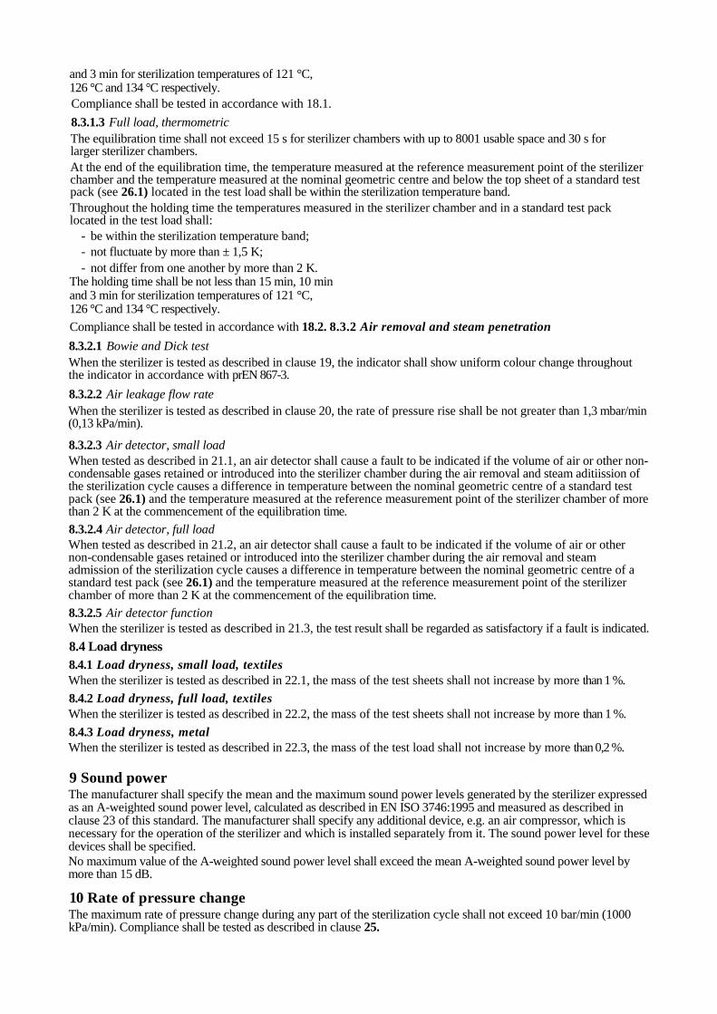
and 3 min for sterilization temperatures of 121 °C, 126 °C and 134 °C respectively.
Compliance shall be tested in accordance with 18.1.
8.3.1.3 Full load, thermometric
The equilibration time shall not exceed 15 s for sterilizer chambers with up to 8001 usable space and 30 s for larger sterilizer chambers.
At the end of the equilibration time, the temperature measured at the reference measurement point of the sterilizer chamber and the temperature measured at the nominal geometric centre and below the top sheet of a standard test pack (see 26.1) located in the test load shall be within the sterilization temperature band.
Throughout the holding time the temperatures measured in the sterilizer chamber and in a standard test pack located in the test load shall:
- be within the sterilization temperature band;
- not fluctuate by more than ± 1,5 K;
- not differ from one another by more than 2 K. The holding time shall be not less than 15 min, 10 min and 3 min for sterilization temperatures of 121 °C, 126 °C and 134 °C respectively.
Compliance shall be tested in accordance with 18.2. 8.3.2 Air removal and steam penetration
8.3.2.1 Bowie and Dick test
When the sterilizer is tested as described in clause 19, the indicator shall show uniform colour change throughout the indicator in accordance with prEN 867-3.
8.3.2.2 Air leakage flow rate
When the sterilizer is tested as described in clause 20, the rate of pressure rise shall be not greater than 1,3 mbar/min (0,13 kPa/min).
8.3.2.3 Air detector, small load
When tested as described in 21.1, an air detector shall cause a fault to be indicated if the volume of air or other non-condensable gases retained or introduced into the sterilizer chamber during the air removal and steam aditiission of the sterilization cycle causes a difference in temperature between the nominal geometric centre of a standard test pack (see 26.1) and the temperature measured at the reference measurement point of the sterilizer chamber of more than 2 K at the commencement of the equilibration time.
8.3.2.4 Air detector, full load
When tested as described in 21.2, an air detector shall cause a fault to be indicated if the volume of air or other non-condensable gases retained or introduced into the sterilizer chamber during the air removal and steam admission of the sterilization cycle causes a difference in temperature between the nominal geometric centre of a standard test pack (see 26.1) and the temperature measured at the reference measurement point of the sterilizer chamber of more than 2 K at the commencement of the equilibration time.
8.3.2.5 Air detector function
When the sterilizer is tested as described in 21.3, the test result shall be regarded as satisfactory if a fault is indicated.
8.4 Load dryness
8.4.1 Load dryness, small load, textiles
When the sterilizer is tested as described in 22.1, the mass of the test sheets shall not increase by more than 1 %.
8.4.2 Load dryness, full load, textiles
When the sterilizer is tested as described in 22.2, the mass of the test sheets shall not increase by more than 1 %.
8.4.3 Load dryness, metal
When the sterilizer is tested as described in 22.3, the mass of the test load shall not increase by more than 0,2 %.
9 Sound power
The manufacturer shall specify the mean and the maximum sound power levels generated by the sterilizer expressed as an A-weighted sound power level, calculated as described in EN ISO 3746:1995 and measured as described in clause 23 of this standard. The manufacturer shall specify any additional device, e.g. an air compressor, which is necessary for the operation of the sterilizer and which is installed separately from it. The sound power level for these devices shall be specified.
No maximum value of the A-weighted sound power level shall exceed the mean A-weighted sound power level by more than 15 dB.
10 Rate of pressure change
The maximum rate of pressure change during any part of the sterilization cycle shall not exceed 10 bar/min (1000 kPa/min). Compliance shall be tested as described in clause 25.
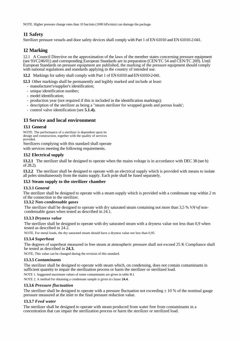
NOTE. Higher pressure change rates than 10 bar/min (1000 kPa/min) can damage the package.
11 Safety
Sterilizer pressure vessels and door safety devices shall comply with Part 1 of EN 61010 and EN 61010-2-041.
12 Marking
12.1 A Council Directive on the approximation of the laws of the member states concerning pressure equipment (see 93/C246/01) and corresponding European Standards are in preparation (CEN/TC 54 and CEN/TC 269). Until European Standards on pressure equipment are published, the marking of the pressure equipment should comply with national regulations and standards applying in the country of intended use.
12.2 Markings for safety shall comply with Part 1 of EN 61010 and EN 61010-2-041.
12.3 Other markings shall be permanently and legibly marked and include at least: - manufacturer's/supplier's identification; - unique identification number; - model identification; - production year (not required if this is included in the identification markings); - description of the sterilizer as being a "steam sterilizer for wrapped goods and porous loads'; - control valve identification (see 5.1.4).
13 Service and local environment
13.1 General
NOTE. The performance of a sterilizer is dependent upon its design and construction, together with the quality of services provided. Sterilizers complying with this standard shall operate
with services meeting the following requirements.
13.2 Electrical supply
13.2.1 The sterilizer shall be designed to operate when the mains voltage is in accordance with DEC 38 (see b) of 28.2).
13.2.2 The sterilizer shall be designed to operate with an electrical supply which is provided with means to isolate all poles simultaneously from the mains supply. Each pole shall be fused separately.
13.3 Steam supply to the sterilizer chamber
13.3.1 General
The sterilizer shall be designed to operate with a steam supply which is provided with a condensate trap within 2 m of the connection to the sterilizer. 13.3.2 Non-condensable gases
The sterilizer shall be designed to operate with dry saturated steam containing not more than 3,5 % VA^of non-condensable gases when tested as described in 24.1.
13.3.3 Dryness value
The sterilizer shall be designed to operate with dry saturated steam with a dryness value not less than 0,9 when tested as described in 24.2.
NOTE. For metal loads, the dry saturated steam should have a dryness value not less than 0,95.
13.3.4 Superheat
The degrees of superheat measured in free steam at atmospheric pressure shall not exceed 25 K Compliance shall be tested as described in 24.3.
NOTE, This value can be changed during the revision of this standard.
13.3.5 Contaminants
The sterilizer shall be designed to operate with steam which, on condensing, does not contain contaminants in sufficient quantity to impair the sterilization process or harm the sterilizer or sterilized load. NOTE 1. Suggested maximum values of some contaminants are given in table B.I.
NOTE 2. A method for obtaining a condensate sample is given in clause 24.4.
13.3.6 Pressure fluctuation
The sterilizer shall be designed to operate with a pressure fluctuation not exceeding ± 10 % of the nominal gauge pressure measured at the inlet to the final pressure reduction value.
13.3.7 Feed water
The sterilizer shall be designed to operate with steam produced from water free from contaminants in a concentration that can impair the sterilization process or harm the sterilizer or sterilized load.
NOTE. Suggested maximum values of some contaminants are given in table B.I.
13.4 Water
The sterilizer shall be designed to operate with water which is of potable quality and supplied at a temperature not exceeding 15 °C. NOTE 1. The temperature of water should be as low as possible because of the effect of temperature on the performance of the vacuum system. Higher water temperatures can modify the specified vacuum levels,
NOTE 2. The hardness value of water, S (ions of alkaline earth), should be between 0,7 mmol/1 and 2,0 mmol/L Hardness values outside these limits can cause scaling and corrosion problems.
NOTE 3. National regulations can require a backfiow protection device to be fitted.
13.5 Compressed air
The sterilizer shall be designed to operate with a compressed air supply at a pressure of 5 bar to 7 bar (500 kPa to 700 kPa), free of liquid water, filtered to 25 (xm and free from oil droplets greater than 2 fxm (see e) of 28.2).
13.6 Electromagnetic interference
The immunity of the sterilizer to electromagnetic interference shall comply with Part 1 or Part 2 of EN 50082, as appropriate.
The emission of electromagnetic interference from the sterilizer shall comply with Part 1 or Part 2 of EN 50081, as appropriate.
The supplier shall state with which of these Parts of EN 50081 and EN 50082 the sterilizer complies (see o) of 28.2).
13.7 Drains
The sterilizer shall be designed to operate with a drainage system resistant to water at 100 °C, and be capable of passing the maximum flow rate of water, air and condensed steam.
NOTE. National regulations can require the drain be trapped and vented and not connected to other drains which can cause a back pressure or obstruction to flow. An air break can also be necessary.
13.8 Supporting surface (floors)
The sterilizer shall be designed to operate when installed on a surface which is horizontal within the tolerance limits specified in tables 1 and 2 (see 4.4), and which will support the maximum floor loading specified by the manufacturer (see 28.2). NOTE. The floor should be impervious to water and adequate for collecting or draining water spillage from the sterilizer.
13.9 Environment
The sterilizer shall be designed to operate in an ambient temperature and humidity up to 35 °C and 85 % relative humidity respectively. NOTE. This can require the provision of a ventilation system designed and constructed to remove the heat transmitted from the sterilizer and from the sterilized load during unloading (see 6.1.1 and 7.1).
13.10 Service connections
The sterilizer shall be designed to operate with all service connections for fluids (e.g. water, steam, compressed air) provided with an isolating valve and terminating in accordance with the manufacturer's sterilizer specification.
14 Installation checks
NOTE. Installation checks precede the installation test and are carried out to establish that:
- the sterilizer has been provided and installed correctly;
- the sterilizer is safe to operate;
- the sterilizer does not interfere with nearby equipment;
- all connected services are satisfactory.
The installation checks shall confirm that
a) except for the results of the installation tests, the documentation specified in clause 27 and the information specified in 28.2 have been provided;
b) safety systems and devices are in compliance with Part 1 of EN 61010 and EN 61010-2-041;
c) when the sterilizer is operated with an empty sterilizer chamber, the pressure and temperature of each connected service is within the range specified by the manufacturer and there are no leaks of steam, compressed air, water or effluent during any part of the sterilization cycle;
d) during any test or check there is no evidence of electromagnetic interference to or from adjacent equipment (see 13.6);
e) the calibration of temperature and pressure instruments has been checked at the nominal sterilization temperature and pressure and that they comply with 6.2.1.3, 6.2.2.1, 6.2.2,2, 6.3.2.2, 6.3.2.3, 6.3.3.1 and 6.3.3.2.
15 Categories of tests
15.1 Type test
15.1.1 The series of tests listed in table 4 and described in clauses 17 to 25 shall be carried out as type tests.
15.1.2 Sterilizers classed as the same type shall have:
a) the same number of doors in the same configuration;
b) all service connections into the sterilizer chamber in the same orientation; NOTE 1. A mirror image of the original orientation does not constitute a new type.
c) the same control system with all sensors located in the same position and orientation; NOTE 2. Where a change(s) in the control system does not affect the operation of the sterilization cycle, the tests described in 17.1, 17.2 and 17.3 can be omitted in further type tests.
d) the same sterilization cycle.
Whenever the designed operating characteristics of the air removal stage of the sterilization cycle are changed, all the tests except the tests according to 17.1, 17.2 and 17.3 shall be carried out
15.1.3 If all other aspects of design remain the same, the following variations shall not constitute a new type:
a) height of sterilizer chamber location above the floor;
b) differences in the dimensions of the sterilizer chamber not greater than ± 10 % of the dimensions with congruent sterilizer chamber shapes;
c) increasing the time of the plateau period within the sterilization cycle having the same sterilization temperature and the same air removal stage;
d) any change of the design or provenance of equipment, providing there is available documented evidence of validation of the design change to show there is no adverse effect on the performance of the sterilizer which would affect compliance with this standard.
NOTE. For documented evidence of validation of the design change see 4.4.6 of EN ISO 9001: 1994.
Changes or modification of equipment previously identified as not contributing more than 3 dB(A) to the total sound power level shall not require a repeat of the sound power test described in clause 23.
15.2 Works tests
The series of tests listed in table 4 and described in clauses 17 to 25 shall be carried out as works tests.
15.3 Installation test
The series of tests listed in table 4 and described in clauses 17 to 25 shall be carried out as installation tests. NOTE 1. Responsibility for carrying out these tests should be agreed between the manufacturer, supplier and purchaser.
NOTE 2. Additional tests can be required by agreement between the manufacturer or supplier and the purchaser.
16 Test programmes
16.1 For acceptance of the sterilizer each test in the agreed test programme (see table 4) shall be successfully completed in accordance with the requirements specified in this standard.
16.2 If adjustment is made to the sterilizer during the test sequence such that the cycle variables of the sterilization cycle are affected, the test programme shall be repeated.
16.3 Reproducibility of the type test shall be demonstrated by three successive repetitions of each specified test.
16.4 Before carrying out the installation tests, the result of the installation checks (see clause 14) shall be acceptable.
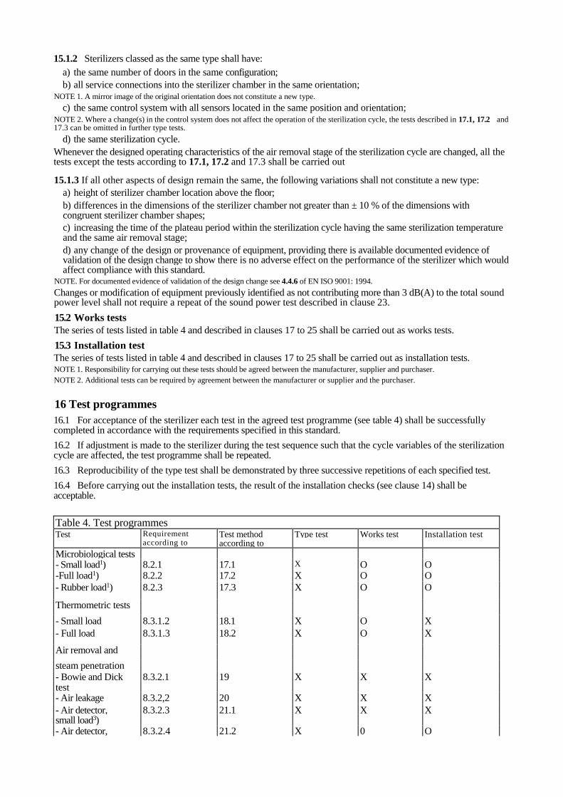
Table 4. Test programmes
Test Requirement Test method Type test Works test Installation test according to according to
Microbiological tests
- Small load1) 8.2.1 17.1 X O O
-Full load1) 8.2.2 17.2 X O O
- Rubber load1) 8.2.3 17.3 X O O
Thermometric tests
- Small load 8.3.1.2 18.1 X O X
- Full load 8.3.1.3 18.2 X O X
Air removal and
steam penetration
- Bowie and Dick 8.3.2.1 19 X X X test
- Air leakage 8.3.2,2 20 X X X
- Air detector, 8.3.2.3 21.1 X X X small load3)
- Air detector, 8.3.2.4 21.2 X 0 O
full load3)
- Air detector 8.3.2.5 21.3 X X X function3)
Load dryness tests
- Small load, 8.4.1 22.1 X O O
textiles - Full load, 8.4.2 22.2 X O X
textiles - Metal load2) 8.4.3 22.3 X O O
Sound power 9 23 X n n
Dynamic chamber 10 25 X O O
pressure
Steam quality tests
- Non-condensable 13.3.2 24.1 O O O
gases
- Dryness value 13.3.3 24.2 O O O
- Superheat 13.3.4 24.3 O O O
X - yes O = optional n = no X) Required when rubber loads are included in the sterilization cycle. 2) Required when metal loads are included in the sterilization cycle. ^ Required when air detector is fitted.
17 Microbiological tests
17.1 Small load, biological indicators
NOTE. The small load test, biological indicators, is intended to show that when connected services comply with the requirements specified in this standard, and the times, temperatures and pressures which control the sterilization cycle are set at the levels at which compliance with the requirements for the small load, thermometric test has been demonstrated, recovery of test organisms from the biological indicator placed in the test load cannot be obtained after the completion of a sterilization cycle.
17.1.1 Apparatus
17.1.1.1 Standard test pack as described in 26.1.
17.1.1.2 Six biological indicators in accordance with prEN 866-3.
17.1.1.3 Connected services complying with clause 13.
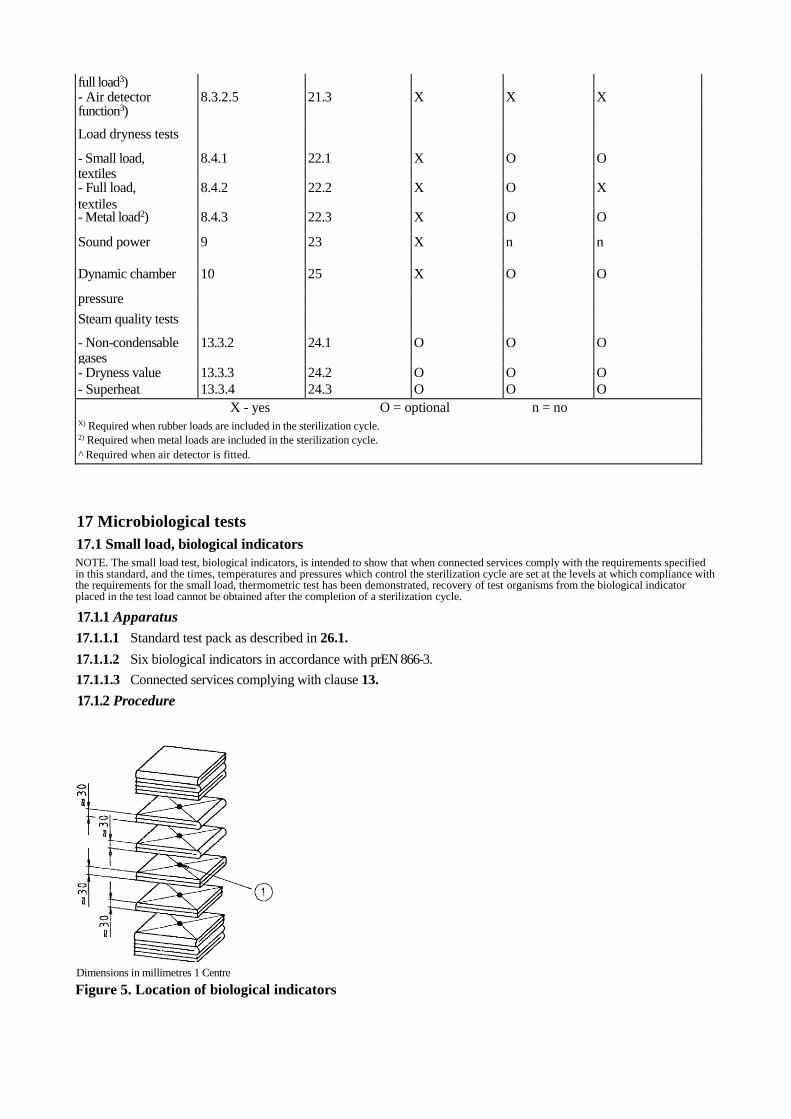
17.1.2 Procedure
Dimensions in millimetres 1 Centre
Figure 5. Location of biological indicators
17.1.2.1 Carry out an air leakage test as described in clause 20. Do not proceed if the air leakage flow rate exceeds that specified in 8.3.2.2.
17.1.2.2 Select the sterilization cycle to be tested.
17.1.2.3 Carry out a sterilization cycle with the sterilizer chamber empty.
17.1.2.4 Remove the wrapping from the standard test pack and place five biological indicators on the vertical geometric axis as shown in figure 5. Reassemble and secure as described in 26.1.
17.1.2.5 Place the standard test pack above the nominal geometric centre of the horizontal plane of the usable space, supported at a distance of between 100 mm and 200 mm above the chamber base.
For sterilizers of one sterilization module the method shall be modified such that the standard test pack is supported above the base of the sterilizer chamber.
17.1.2.6 Carry out a sterilization cycle and take the following measurements.
- Observe and record the time taken, number of pulses, temperatures and pressures and levels of vacuum at all significant parts of the sterilization cycle, e.g. the change from each stage or substage.
- At the beginning, end and middle of the holding time, observe and record the sterilizer chamber temperature and sterilizer chamber pressure.
- Ensure that a recording of the sterilization cycle is made by the recording instrument fitted permanently to the sterilizer (see 6.3).
17.1.2.7 At the completion of the test, proceed as follows:
- Check that a visual display of 'cycle complete is obtained
- Culture the six biological indicators in accordance with the instructions given by the manufacturer of the biological indicators. Examine the five exposed biological indicators for compliance with 8.2.1. The untreated biological indicator shall be demonstrated as being viable or the test shall be regarded as not valid and shall be repeated.
- Examine the records specified above for compliance with the sterilization cycle specification.
17.2 Full load, biological indicators
NOTE. The full load test, biological indicators, is used to demonstrate that, at the levels at which controls are set, test organisms placed in a standard test pack located in a load of specified maximum mass and of sufficient size to fill the usable space cannot be recovered after being subjected to a sterilization cycle.
17.2.1 Apparatus
17.2.1.1 Full load, textiles as described in 26.6.
17.2.1.2 Six biological indicators in accordance with prEN 866-3.
17.2.1.3 Connected services complying with clause 13.
17.2.2 Procedure
17.2.2.1 Carry out an air leakage test as described in clause 20. Do not proceed if the air leakage flow rate exceeds that specified in 8.3.2.2.
17.2.2.2 Select the sterilization cycle to be tested.
17.2.2.3 Carry out a sterilization cycle with the sterilizer chamber empty.
17.2.2.4 Remove the wrapping from the standard test pack and place five biological indicators on the vertical geometric axis as shown in figure 5. Reassemble and secure as described in 26.1.
17.2.2.5 Place the standard test pack and stacks of sheets comprising the test sterilizer load into the usable space as described in 26.6.
17.2.2.6 Carry out a sterilization cycle and take the following measurements.
- Observe and record the time taken, number of pulses, temperatures and pressures and levels of vacuum at all significant parts of the sterilization cycle, e.g. the change from each stage or substage.
- At the beginning, middle and end of the holding time, observe and record the sterilizer chamber temperature and sterilizer chamber pressure.
- Ensure that a recording of the sterilization cycle is made by the recording instrument fitted permanently to the sterilizer (see 6.3).
17.2.2.7 At the completion of the test, proceed as follows.
- Check that a visual display of 'cycle complete' is obtained.
- Culture the six biological indicators in accordance with the instructions given by the manufacturer of the biological indicators. Examine the five exposed biological indicators for compliance with 8.2.2. The untreated biological indicator shall be demonstrated as being viable or the test shall be regarded as not valid and shall be repeated.
- Examine the records specified above for compliance with the sterilization cycle specification.
17.3 Rubber load, biological indicators
NOTE. The rubber load test, biological indicators, is used to demonstrate that, at the levels at which controls are set, test organisms inserted inside a length of rubber tubing, placed into a test pack located in a load of size sufficient to fill the usable space cannot be
recovered after being subjected to a sterilization cycle.
17.3.1 Apparatus
17.3.1.1 Test pack, rubber, as described in 26.7.
17.3.1.2 Natural rubber objects sufficient to fill the usable space and capable of withstanding dry saturated steam at temperatures up to a maximum of 126 °C.
17.3.1.3 Baskets, each equivalent in size to one sterilization module.
17.3.1.4 One biological indicator from the same batch as those used to form the test packages described in 26.7.
17.3.1.5 Connected services complying with clause 13.
17.3.1.6 Stop watch with an error of not more than — 0,5 s over a period of 15 min.
17.3.2 Procedure
17.3.2.1 Carry out an air leakage test as described in clause 20. Do not proceed if the air leakage flow rate exceeds that specified in 8.3.2.2.
17.3.2.2 Select the sterilization cycle to be tested.
17.3.2.3 Carry out a sterilization cycle with the sterilizer chamber empty.
17.3.2.4 Open the sterilizer door and start the stopwatch.
17.3.2.5 Leave the sterilizer door open for a period of at least 30 min.
17.3.2.6 Place the test pack, rubber, in position in the usable space identified by the manufacturer as the most difficult to sterilize. Fill the remainder of the usable space with baskets, each containing approximately 2,2 kg of natural rubber objects.
17.3.2.7 Carry out a sterilization cycle and take the following measurements.
- Observe and record the time taken, number of pulses, temperatures and pressures and levels of vacuum at all significant parts of the sterilization cycle, e.g. the change from each stage or substage.
- At the beginning, middle and end of the holding time, observe and record the sterilizer chamber temperature and sterilizer chamber pressure.
- Ensure that a recording of the sterilization cycle is made by the recording instrument fitted permanently to the sterilizer (see 6.3).
17.3.2.8 At the completion of the test, proceed as follows.
- Check that a visual display of 'cycle complete' is obtained.
- Culture the 10 biological indicators in accordance with the instructions given by the manufacturer of the biological indicators. Examine the nine exposed biological indicators for compliance with 8.2,3. The untreated biological indicator shall be demonstrated as being viable or the test shall be regarded as not valid and shall be repeated.
- Examine the records specified above for compliance with the sterilization cycle specification.
18 Thermometric tests
18.1 Small load, thermometric
NOTE. The small load test, thermometric is used to demonstrate that, after the air removal stage of the sterilization cycle, sterilizing conditions are obtained within the sterilizer chamber and standard test pack. The standard test pack is chosen to represent the maximum density of porous load material which a sterilizer conforming to this standard is designed to process. The more air there is to remove, the more exacting will be the test; that is why this pack is used by itself in an otherwise empty sterilizer chamber.
18.1.1 Apparatus
18.1.1.1 Standard test pack as described in 26.1.
18.1.1.2 Thermometric recording instrument as described in 26.4.
18.1.1.3 Three temperature sensors as described in 26.3.
18.1.1.4 Connection fitting with a pipe thread ISO 228-G1A through which the temperature sensors can be introduced into the sterilizer chamber without affecting its vacuum-tightness and pressure-tightness (see figure 6).
18.1.1.5 Connected services complying with clause 13.
18.1.2 Procedure
18.1.2.1 Introduce the temperature sensors into the sterilizer chamber through the temperature sensor entry connection and fitting.
18.1.2.2 Carry out an air leakage test as described in clause 20. Do not proceed if the air leakage flow rate exceeds that specified in 8.3.2.2.
18.1.2.3 Place one of the temperature sensors either in the active drain to a depth of at least 10 mm or at the reference measurement point. 18.1.2.4 Select the sterilization cycle to be tested.
18.1.2.5 Carry out a sterilization cycle with the sterilizer chamber empty.
18.1.2.6 Remove the wrapping from the standard test pack and place one temperature sensor at the nominal geometric centre of the standard test pack. Reassemble and secure as described in 26.1.
18.1.2.7 Place the standard test pack above the nominal geometric centre of the horizontal plane of the usable space, supported at a distance of between 100 mm and 200 mm above the chamber base.
For sterilizers of one sterilization module, the method shall be modified such that the standard test pack is supported above the base of the sterilizer chamber.
18.1.2.8 Secure the third temperature sensor 50 mm above the upper surface of the test pack and on its nominal vertical centre. For sterilizers of one sterilization module, the method shall be modified such that the standard test pack is supported above the base of the sterilizer chamber and the third temperature sensor is located in the usable chamber space within 50 mm over the standard test pack.
18.1.2.9 Carry out a sterilization cycle and take the following measurements.
- Observe and record the time taken, number of pulses, temperatures and pressures and levels of vacuum at all significant parts of the sterilization e.g. the change from each stage or substage.
- At the beginning, middle and end of the holding time, observe and record the sterilizer chamber temperature and sterilizer chamber pressure.
- Ensure that a recording of the sterilization cycle is made by the recording instrument fitted permanently to the sterilizer (see 6.3).
18.1.2.10 On completion of the test, proceed as follows.
- Check that a visual display of 'cycle complete is obtained
- Examine the records for compliance with the performance requirements specified in 8.3.1.2.
- Examine the records specified above for compliance with the sterilization cycle specification.
18.2 Full load, thermometric
NOTE. The full load test, thermometric is used to demonstrate that, at the levels at which the controls are set, the required sterilizing conditions will be produced in a test load of specified maximum mass and of sufficient size to fill the usable space.
18.2.1 Apparatus
18.2.1.1 Full load, textiles, as described in 26.6.
18.2.1.2 Thermometric recording instrument as described in 26.4.
18.2.1.3 Three temperature sensors as described in 26.3.
18.2.1.4 Connection fitting with a pipe thread ISO 228-G1A through which the temperature sensors can be introduced into the sterilizer chamber without affecting its vacuum-tightness and pressure-tightness (see figure 6).
18.2.1.5 Connected services complying with clause 13.
18.2.2 Procedure
18.2.2.1 Introduce the temperature sensors into the sterilizer chamber through the temperature sensor entry connection and fitting.
18.2.2.2 Carry out an air leakage test as described in clause 20. Do not proceed if the air leakage flow rate exceeds that specified in 8.3.2.2.
18.2.2.3 Place one of the temperature sensors either into the active drain to a depth of at least 10 mm or at the reference measurement point
18.2.2.4 Select the sterilization cycle to be tested.
18.2.2.5 Carry out a sterilization cycle with the sterilizer chamber empty.
18.2.2.6 Remove the wrapping from the standard test pack and place one temperature sensor at the nominal geometric centre and one below the top sheet. Reassemble and secure as described in 26.1.
18.2.2.7 Place the standard test pack and stacks of sheets comprising the test sterilizer load into the usable space as described in 26.6.
18.2.2.8 Carry out a sterilization cycle and take the following measurements.
- Observe and record the time taken, number of pulses, temperatures and pressures and levels of vacuum at all significant parts of the sterilization cycle, e.g. the change from each stage or substage.
- At the beginning, middle and end of the holding time, observe and record the sterilizer chamber temperature and sterilizer chamber pressure.
- Ensure that a recording of the sterilization cycle is made by the recording instrument fitted permanently to the sterilizer (see 6.3).
18.2.2.9 At the completion of the test, proceed as follows.
- Check that a visual display of 'cycle complete' is obtained.
- Examine the records and sheets comprising the standard test pack for compliance with the performance requirements specified in 8.3.1.3.
- Examine the records specified above for compliance with the sterilization cycle specification.
19 Bowie and Dick test
NOTE. The Bowie and Dick test was conceived as a test for successful air removal for so-called high-vacuum porous load sterilizers. A successful Bowie and Dick test indicates rapid and even penetration of steam into the test pack. Retention of air within the pack due to:
- an inefficient air removal stage;
- the presence of an air leak during the air removal stage;
. ' - the presence of non-condensable gases in the steam supply;
are circumstances which can lead to failure of the test
The result of the test can also be affected by other factors which inhibit steam penetration. A failure of the test is therefore not conclusive
proof that a fault is due to air retention, air leakage or non-condensable gases, and other causes of failure may need to be eliminated.
19.1 Apparatus
19.1.1 Standard test pack as described in 26.1.
19.1.2 Indicator in accordance with prEN 867-3.
19.1.3 Connected services complying with clause 13.
19.2 Procedure
19.2.1 Select the sterilization cycle to be tested (see 7.1.14).
19.2.2 Carry out a sterilization cycle with the sterilizer chamber empty and without any extended drying time.
19.2.3 Remove the wrapping from the standard test pack and place the indicator in the sheet located in the approximate centre of the standard test pack. Reassemble and secure as described in 26.1.
19.2.4 Place the standard test pack above the nominal geometric centre of the horizontal plane of the usable space supported at a distance of between 100 mm and 200 mm above the chamber base.
For sterilizers of one sterilization module the method shall be modified such that the standard test pack is supported above the base of the sterilizer chamber.
19.2.5 Carry out a sterilization cycle in accordance with the manufacturer's operating procedure.
19.2.6 At the end of the test examine the indicator for compliance with the requirement specified in 8.3.2.1.
20 Air leakage test
NOTE. Hie air leakage test is used to demonstrate that the quantity of air leakage into the sterilizer chamber during the periods of vacuum does not exceed a level which will inhibit the penetration of steam into the sterilizer load and will not be a potential risk to the re-contamination of the sterilizer load during drying.
20.1 Apparatus
20.1.1 Test pressure gauge (0 mbar to 160 mbar) as described in 26.2.
If the sterilizer is fitted with an absolute pressure instrument complying with 26.2 this additional gauge is not required.
20.1.2 Stopwatch, with an error of not more than i 0,5 s over a period of 15 min.
20.1.3 Connected services complying with clause 13.
20.2 Procedure
20.2.1 Connect the test pressure gauge to the sterilizer chamber with a means to protect it from a gauge pressure of 2,8 bar (280 kPa) if it is not designed to operate up to 2,8 bar (280 kPa).
20.2.2 Stabilize the temperature of the sterilizer chamber (see note) by carrying out one of the following:
- if the pressure vessel incorporates a heated jacket, carry out a sterilization cycle with the sterilizer chamber empty;
- if the pressure vessel does not incorporate a heated jacket, ensure that the temperature of the sterilizer chamber
is not more than 20 K from ambient NOTE. As an example, in a closed vessel at 40 mbar absolute pressure (4 kPa), the pressure changes by approximately 1 mbar (0,1 kPa) for each 10 K change in temperature, over the range 20 °C to 140 °C; at 70 mbar (7 kPa) the change is approximately 2 mbar (0,2 kPa). The test can be compromised if the temperature changes by more than 10 K during the period in which the chamber pressure is monitored.
20.2.3 With the temperature stabilized and the sterilizer chamber empty except for fixed furniture and necessary monitoring sensors, start the test cycle. When the pressure in the sterilizer chamber is 70 mbar absolute (7 kPa) or below, close all the valves connected to the sterilizer chamber and stop the vacuum pump. Observe and record the time (ti) and the absolute pressure (pi). Wait for at least (300 ± 10) s to allow evaporation of condensation in the chamber and then observe and record the absolute pressure (P2) in the sterilizer chamber and the time (£2). After a further (600 ± 10) s, again observe and record the absolute pressure (p%) and the time (%). NOTE. The sterilizer can be fitted with a test cycle for air leakage which will carry out this procedure automatically and display the air leakage in mbar/min,
20.2.4 At the end of the test calculate the rate of pressure rise for the 600 s period and check for compliance with 8.3.2.2.
NOTE. If the value of (#2 - Pi) is greater than 20 mbar (2 kPa), this can be due to the initial presence of excessive condensate in the sterilizer chamber.
21 Air detector tests
NOTE. An air detector can be fitted to a sterilizer and used to determine whether the non-condensable gases contained in the steam delivered to the sterilizer and the air remaining after the air removal stage of the sterilization cycle are sufficient to cause the sterilizing process to be of uncertain efficacy.
21.1 Air detector, small load
21.1.1 Apparatus
21.1.1.1 Standard test pack as described in 26.1.
21.1.1.2 Thermometric recording instrument as described in 26.4.
21.1.1.3 Two temperature sensors as described in 26.3.
21.1.1.4 Connection fitting with a pipe thread ISO 228-G1A through which the temperature sensors can be introduced into the sterilizer chamber without affecting its vacuum-tightness and pressure-tightness (see figure 6).
21.1.1.5 Metering device as described in 26.9.
21.1.1.6 Test pressure gauge (0 mbar to 160 mbar) as described in 26.2.
21.1.1.7 Connected services complying with clause 13.
21.1.2 Procedure
21.1.2.1 Connect the metering device to the sterilizer chamber using the valved port provided by the manufacturer.
21.1.2.2 Connect the test pressure gauge to the sterilizer chamber with a means to protect it from a gauge pressure of 2,8 bar (280 kPa) if it is not designed to operate up to 2,8 bar (280 kPa).
21.1.2.3 Introduce the two temperature sensors into the sterilizer chamber through the temperature sensor entry connection and fitting.
21.1.2.4 Carry out an air leakage test as described in clause 20. Do not proceed if the air leakage flow rate exceeds that specified in 8.3.2.2.
21.1.2.5 Place one of the temperature sensors either into the active drain in contact with the condensate to a depth of at least 10 mm or at the reference measurement point.
21.1.2.6 Select the sterilization cycle to be tested
21.1.2.7 Carry out a sterilization cycle with the sterilizer chamber empty.
21.1.2.8 Remove the wrapping from the standard test pack and place the other temperature sensor at the nominal geometric centre of the standard test pack. Reassemble and secure as described in 26.1.
21.1.2.9 Place the standard test pack above the nominal geometric centre of the horizontal plane of the usable space, supported at a distance of between 100 mm and 200 mm above the sterilizer chamber base.
For sterilizers of one sterilization module the method shall be modified such that the standard test pack is supported above the base of the sterilizer chamber.
21.1.2.10 Carry out a sterilization cycle, but during the air removal stage admit air to the sterilizer chamber by means of the metering device. Control the rate of entry of the air so that, at the start of the plateau period, the temperature measured at the centre of the standard test pack is not more than 2 K lower than the temperature measured in the active drain or at the reference measurement point.
NOTE. It can be necessary to conduct a number of tests in order to establish the air leakage required.
21.1.2.11 Carry out a further air leakage test as described in clause 20 and then calculate the air leakage flow rate.
21.1.2.12 If the air leakage causes the sterilizer chamber pressure to rise more than 11 mbar/min (1,1 kPa/min), re-adjust the metering device to cause a pressure rise of (10 ± 1) mbar/min [(1,0 ± 0,1) kPa/min].
21.1.2.13 Carry out a sterilization cycle and check that a fault is indicated either during or at the end of the sterilization cycle.
NOTE. To facilitate subsequent re-testing it is advisable to record the setting of the metering device at which the air detector causes a fault to be indicated.
21.2 Air detector, full load
21.2.1 Apparatus
21.2.1.1 Full load, textiles as described in 26.6.
21.2.1.2 Therniometric recording instrument as described in 26.4.
21.2.1.3 Two temperature sensors as described in 26.3.
21.2.1.4 Connection fitting with a pipe thread ISO 228-G1A through which the temperature sensors can be introduced into the sterilizer chamber without affecting its vacuum-tightness and pressure-tightness (see figure 6).
21.2.1.5 Metering device as described in 26.9.
21.2.1.6 Test pressure gauge (0 mbar to 160 mbar) as described in 26.2.
21.2.1.7 Connected services complying with clause 13.
21.2.2 Procedure
21.2.2.1 Ensure that the sterilizer complies with the requirements for the air detector test, small load (see 8.3.2.3).
21.2.2.2 Connect the metering device to the sterilizer chamber using the valved port provided by the manufacturer.
21.2.2.3 Connect the test pressure gauge to the sterilizer ejiamber with a means to protect it from a gauge pressure of 2,8 bar (280 kPa) if it is not designed to operate up to 2,8 bar (280 kPa).
21.2.2.4 Introduce the two temperature sensors into the sterilizer chamber through the temperature sensor entry connection and fitting.
21.2.2.5 Carry out an air leakage test as described in clause 20. Do not proceed if the air leakage flow rate exceeds that specified in 8.3.2.2.
21.2.2.6 Place one of the temperature sensors either in the active drain to a depth of at least 10 mm or at the reference measurement point.
21.2.2.7 Select the sterilization cycle to be tested.
21.2.2.8 Carry out a sterilization cycle with the sterilizer chamber empty.
21.2.2.9 Remove the wrapping from the standard test pack and place the other temperature sensor at the nominal geometric centre of the standard test pack. Reassemble and secure as described in 26.1.
21.2.2.10 Place the standard test pack as part of the full load in the sterilizer chamber as described in 26.6.
21.2.2.11 Carry out a sterilization cycle but during the air removal stage admit air to the sterilizer chamber by means of the metering device. Control the rate of entry of air so that, at the start of the plateau period, the temperature measured at the centre of the standard test pack is not more than 2 K lower than the temperature measured in the active drain or at the reference measurement point. NOTE. It can be necessary to conduct a number of tests in order to establish the air leakage required.
21.2.2.12 Carry out a further air leakage test as described in clause 20 and then calculate the air leakage flow rate.
21.2.2.13 If the air leakage causes the sterilizer chamber pressure to rise more than 11 mbar/min (1,1 kPa/min), re-adjust the metering device to cause a pressure rise of (10 ± 1) mbar/min [(1,0 ± 0,1) kPa/minj.
21.2.2.14 Carry out a sterilization cycle and check that the air detector causes a fault to be indicated either during or at the end of the test cycle. NOTE. To facilitate subsequent re-testing it is advisable to record the setting of the metering device at which the air detector causes a fault to be indicated,
21.3 Air detector function
NOTE. The air detector function test is used to provide assurance that the setting of the air detector remains valid.
21.3.1 Apparatus
21.3.1.1 Standard test pack as described in 26.1.

21.3.1.2 Metering device as described in 26.9.
21.3.1.3 Connected services complying with clause 13.
21.3.2 Procedure
21.3.2.1 If a metering device is not already connected, connect one to the sterilizer chamber using the valved port provided by the manufacturer.
21.3.2.2 Carry out an air leakage test as described in clause 20. Do not proceed if the air leakage flow rate exceeds that specified in 8.3.2.2.
21.3.2.3 Select the sterilization cycle to be tested.
21.3.2.4 Carry out a sterilization cycle with the sterilizer chamber empty.
21.3.2.5 Open the valve on the port designated by the manufacturer.
21.3.2.6 Set the metering device to the setting determined during the air detector test (see 21.1).
21.3.2.7 Place the standard test pack above the nominal geometric centre of the horizontal plane of the usable space supported at a distance of between 100 mm and 200 mm above the sterilizer chamber base.
For sterilizers of one sterilization module the method shall be modified such that the standard test pack is supported above the base of the sterilizer chamber.
21.3.2.8 Carry out a sterilization cycle.
21.3.2.9 At the end of the sterilization cycle check for compliance with the requirement specified in 8.3.2.5.
21.3.2.10 Close the valve on the port designated by the manufacturer.
22 Load dryness tests
22.1 Load dryness, small load, textiles
NOTE, The load dryness test, small load textiles, is used to demonstrate that the sterilization cycle without extended drying will not cause an increase in moisture in a standard test pack sufficient for there to be uncertainty in the dryness of sterilizer loads routinely sterilized.
22.1.1 Apparatus
22.1.1.1 Standard test pack as described in 26.1.
22.1.1.2 Polyethylene bags, three, 350 mm X 250 mm or larger, manufactured from polyethylene sheet with a thickness not less than 250 juim.
22.1.1.3 Balance, capable of weighing a load of at least 1 kg and with an accuracy of at least - 0,1 g.
22.1.1.4 Indelible marker.
22.1.1.5 Stopwatch.
22.1.1.6 Connected services complying with clause 13.
22.1.2 Procedure
22.1.2.1 Allow the sheets of the standard test pack to equilibrate, as described in 26.1.
22.1.2.2 Mark three of the sheets of the standard test pack and similarly mark each of the polyethylene bags so that all are individually identified.
22.1.2.3 Weigh each of the polyethylene bags (mi).
22.1.2.4 Place one of the marked sheets in each of the bags, weigh each bag and record its mass (m%).
22.1.2.5 Remove the sheets from the bags and replace them in the standard test pack; place one in the centre and one in the second sheet from either end of the standard test pack. Secure the standard test pack as described in 26.1.
22.1.2.6 Select the sterilization cycle to be tested.
22.1.2.7 Carry out the cycle to be tested with the sterilizer chamber empty.
22.1.2.8 Place the standard test pack above the nominal geometric centre of the horizontal plane of the usable space supported at a distance of between 100 mm and 200 mm above the chamber base.
For sterilizers of one sterilization module the method shall be modified such that the standard test pack is supported above the base of the sterilizer chamber.
Carry out a sterilization cycle. Start the sterilization cycle within 60 s of placing the test pack in the sterilizer chamber.
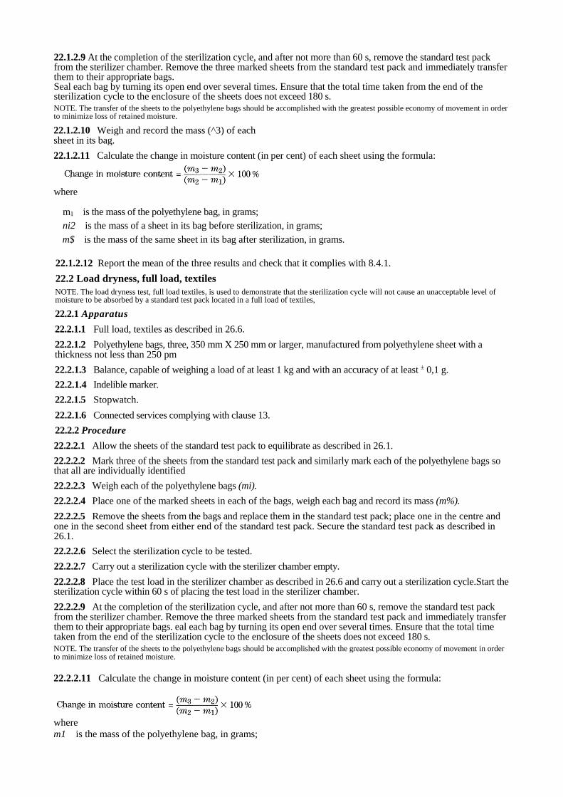
22.1.2.9 At the completion of the sterilization cycle, and after not more than 60 s, remove the standard test pack from the sterilizer chamber. Remove the three marked sheets from the standard test pack and immediately transfer them to their appropriate bags. Seal each bag by turning its open end over several times. Ensure that the total time taken from the end of the sterilization cycle to the enclosure of the sheets does not exceed 180 s. NOTE. The transfer of the sheets to the polyethylene bags should be accomplished with the greatest possible economy of movement in order to minimize loss of retained moisture.
22.1.2.10 Weigh and record the mass (^3) of each sheet in its bag.
22.1.2.11 Calculate the change in moisture content (in per cent) of each sheet using the formula:
where
m1 is the mass of the polyethylene bag, in grams;
ni2 is the mass of a sheet in its bag before sterilization, in grams;
m$ is the mass of the same sheet in its bag after sterilization, in grams.
22.1.2.12 Report the mean of the three results and check that it complies with 8.4.1.
22.2 Load dryness, full load, textiles
NOTE. The load dryness test, full load textiles, is used to demonstrate that the sterilization cycle will not cause an unacceptable level of moisture to be absorbed by a standard test pack located in a full load of textiles,
22.2.1 Apparatus
22.2.1.1 Full load, textiles as described in 26.6.
22.2.1.2 Polyethylene bags, three, 350 mm X 250 mm or larger, manufactured from polyethylene sheet with a thickness not less than 250 pm
22.2.1.3 Balance, capable of weighing a load of at least 1 kg and with an accuracy of at least ± 0,1 g.
22.2.1.4 Indelible marker.
22.2.1.5 Stopwatch.
22.2.1.6 Connected services complying with clause 13.
22.2.2 Procedure
22.2.2.1 Allow the sheets of the standard test pack to equilibrate as described in 26.1.
22.2.2.2 Mark three of the sheets from the standard test pack and similarly mark each of the polyethylene bags so that all are individually identified
22.2.2.3 Weigh each of the polyethylene bags (mi).
22.2.2.4 Place one of the marked sheets in each of the bags, weigh each bag and record its mass (m%).
22.2.2.5 Remove the sheets from the bags and replace them in the standard test pack; place one in the centre and one in the second sheet from either end of the standard test pack. Secure the standard test pack as described in 26.1.
22.2.2.6 Select the sterilization cycle to be tested.
22.2.2.7 Carry out a sterilization cycle with the sterilizer chamber empty.
22.2.2.8 Place the test load in the sterilizer chamber as described in 26.6 and carry out a sterilization cycle.Start the sterilization cycle within 60 s of placing the test load in the sterilizer chamber.
22.2.2.9 At the completion of the sterilization cycle, and after not more than 60 s, remove the standard test pack from the sterilizer chamber. Remove the three marked sheets from the standard test pack and immediately transfer them to their appropriate bags. eal each bag by turning its open end over several times. Ensure that the total time taken from the end of the sterilization cycle to the enclosure of the sheets does not exceed 180 s.
NOTE. The transfer of the sheets to the polyethylene bags should be accomplished with the greatest possible economy of movement in order to minimize loss of retained moisture.
22.2.2.11 Calculate the change in moisture content (in per cent) of each sheet using the formula:
where m1 is the mass of the polyethylene bag, in grams;
m2 is the mass of a sheet in its bag before sterilization, in grams; m3 is the mass of the same sheet in its bag after sterilization, in grams.
22.2.2.12 Report the mean of the three results and check that it complies with 8.4.2.
22.3 Load dryness, metal load
NOTE 1. The load dryness test, metal, is performed with a reference sterilizer load and is used to demonstrate that the sterilization
cycle is unlikely to cause moisture problems in routine production loads.
NOTE 2. If moisture problems are identified after the test has been successfully completed the cause can be the type of load and its location
in the sterilizer chamber.
22.3.1 Apparatus
22.3.1.1 Test pack, metal as described in 26.8.
22.3.1.2 Balance, capable of weighing a load of at least 15 kg and with an accuracy of at least ± 1 g.
22.3.1.3 Stopwatch.
22.3.1.4 Connected services complying with clause 13.
22.3.2 Procedure
22.3.2.1 Ensure that all items used to form the test pack shall be equilibrated to ambient conditions.
22.3.2.2 Weigh the test pack, metal, and record its mass (mi).
22.3.2.3 Select the sterilization cycle to be tested.
22.3.2.4 Carry out a sterilization cycle with the sterilizer chamber empty.
22.3.2.5 Place the test pack, metal, in the usable space, on the lower shelf.
22.3.2.6 Fill the remaining usable space with steel objects to give an approximate mass of 24 kg in each sterilization
module.
All items shall be equilibrated to ambient conditions.
22.3.2.7 Carry out a sterilization cycle.
22.3.2.8 At the completion of the sterilization cycle remove the test pack, metal, from the sterilizer chamber and
weigh, within a total period of 5 min.
Record its mass (wi<£).
22.3.2.9 Calculate the change in moisture content (in per cent) using the formula:
where
m1 is the mass of the polyethylene bag, in grams;
m2 is the mass of a sheet in its bag before sterilization, in grams;
m% is the mass of the same sheet in its bag after sterilization, in grams.
22.3.2.10 Check that the result complies with 8.4.3.
23 Sound power test
NOTE. National legislation controls the perceived noise (sound pressure) in the working environment. Sound pressure levels sensed in a room
are a function of the sound power generated by the source, e.g. the sterilizer, and the acoustic design of the room in which the source is
installed. The purpose of this test is to ensure compliance with the requirement for peak sound power generated by a sterilizer and to
ensure that the level of the weighted sound power is known and available for the design of the installation.
23.1 Apparatus
23.1.1 A sound level meter, complying with Type 1 of EN 60651: 1994 or an integrating averaging sound level meter,
complying with Type 1 of EN 60804 :1994.
23.1.2 Test room, with a sound reflecting floor (e.g. tiles, concrete).
23.1.3 Full load, textiles, as described in 26.6.
23.2 Procedure
23.2.1 Locate the microphones in the position described in 7.3.1 of EN ISO 3746:1995.
NOTE 1. The reference surface is the smallest rectangular parallelepiped (box) that just encloses the sterilizer. It is a box formed by the
structure and coverings or, where these are not fitted, it is a box having a width and depth measured from the outside of the vessel lagging
and a height measured from the floor to the top of the vessel lagging.
NOTE 2. The reference surface does not include pipes and valves used to connect the sterilizer to its services.
23.2.2 Determine the environment correction factor K
as described in A.3 of EN ISO 3746: 1995. This value
shall not exceed the value given in 8.2 of
EN ISO 3746:1995.
23.2.3 With the sterilizer containing the test load carry
out the test, ensuring that the pressure and flow from
the steam and water services are set to levels which
cause the maximum noise and are within the ranges
specified for the sterilizer.
NOTE. When the sterilizer is designed for a number of sterilization cycles, the textile cycle employing the highest temperature should be
selected.
23,2.4 Using the procedure for measurements on a rectangular measurement surface described in 7.3 of EN ISO
3746:1995, determine the A-weighted sound power level (!WA) an<i *he maximum sound power level (LWA max)? of
the sterilizer for one complete sterilization cycle.
NOTE. The sound power level is determined from a number of sensor positions. If the sound meter has insufficient input channels, additional
instruments and/or repeated sterilization cycles are performed.
23.3 Test result
Record the calculated mean and maximum A-weighted sound power levels in decibels to the nearest integer and
check that the maximum A-weighted sound power complies with clause 9.
NOTE. Other information should be recorded as required by EN ISO 3746:1995.
24 Steam quality tests
24.1 Non-condensable gases
NOTE 1. The steam quality test, non-condensable gases, is used to demonstrate that the level of non-condensable gases contained in the steam
will not prevent the attainment of sterilization conditions in any part of the sterilizer load. The test method described should be regarded
not as measuring the exact level of non-condensable gases but as a method by which the provision of acceptable steam quality can be
demonstrated.
NOTE 2. An alternative procedure to the one described in 24.1 can be used providing it has been calibrated against this standard.
24.1.1 Apparatus
24.1.1.1 Burette, of 50 ml (nominal) capacity, having a minimum scale mark of 1 ml.
24.1.1.2 Funnel, with parallel sides and a major diameter of approximately 50 mm.
24.1.1.3 Container of 2000 ml (nominal) capacity and with an overflow pipe to limit the contained capacity to approximately 1500 ml.
24.1.1.4 Sampling pipe, TF shaped, made from 6 mm (nominal) outside diameter glass tubing and with a 75 mm (nominal) delivery limb.
24.1.1.5 Small needle valve, having a 1 mm (nominal) orifice and with suitable fittings for connection to the steam pipe and rubber sampling tube.
24.1.1.6 Graduated cylinder of 250 ml (nominal) capacity and having minimum scale mark of 10 ml.
24.1.1.7 Burette stand
24.1.1.8 Rubber tubing (950 ± 50) mm long, self-draining and having a bore suitable for connection to the sampling pipe and needle valve.
24.1.1.9 Temperature measurement system with an accuracy of at least 1 K at 80 °C.
24.1.1.10 One temperature sensor as described in 26.3.
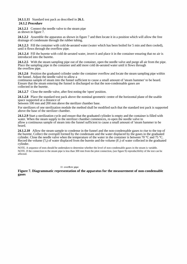
24.1.1.11 Standard test pack as described in 26.1.
24.1.2 Procedure
24.1.2.1 Connect the needle valve to the steam pipe as shown in figure 7.
24.1.2.2 Assemble the apparatus as shown in figure 7 and then locate it in a position which will allow the free drainage of condensate through the rubber tubing.
24.1.2.3 Fill the container with cold de-aerated water (water which has been boiled for 5 min and then cooled), until it flows through the overflow pipe.
24.1.2.4 Fill the burette with cold de-aerated water, invert it and place it in the container ensuring that no air is introduced into the burette.
24.1.2.5 With the steam sampling pipe out of the container, open the needle valve and purge all air from the pipe. Place the sampling pipe in the container and add more cold de-aerated water until it flows through the overflow pipe.
24.1.2.6 Position the graduated cylinder under the container overflow and locate the steam sampling pipe within the funnel. Adjust the needle valve to allow a continuous sample of steam into the funnel sufficient to cause a small amount of 'steam hammer' to be heard. Ensure that the steam entering the funnel is discharged so that the non-condensable gases are collected in the burette.
24.1.2.7 Close the needle valve, after first noting the 'open' position.
24.1.2.8 Place the standard test pack above the nominal geometric centre of the horizontal plane of the usable space supported at a distance of between 100 mm and 200 mm above the sterilizer chamber base.
For sterilizers of one sterilization module the method shall be modified such that the standard test pack is supported above the base of the sterilizer chamber.
24.1.2.9 Start a sterilization cycle and ensure that the graduated cylinder is empty and the container is filled with water. When the steam supply to the sterilizer chamber commences, re-open the needle valve to allow a continuous sample of steam into the funnel sufficient to cause a small amount of 'steam hammer to be heard.
24.1.2.10 Allow the steam sample to condense in the funnel and the non-condensable gases to rise to the top of the burette. Collect the overspill formed by the condensate and the water displaced by the gases in the graduated cylinder. Close the needle valve when the temperature of the water in the container is between 70 °C and 75 °C. Record the volume (7b) of water displaced from the burette and the volume (Fc) of water collected in the graduated cylinder.
NOTE. A sequence of tests should be undertaken to determine whether the level of non-condensable gases in the steam is variable. NOTE. If the connection to the steam pipe is less than 300 mm from the pitot connection, (see figure 9) reproducibility of the test can be affected.
Figure 7. Diagrammatic representation of the apparatus for the measurement of non-condensable gases
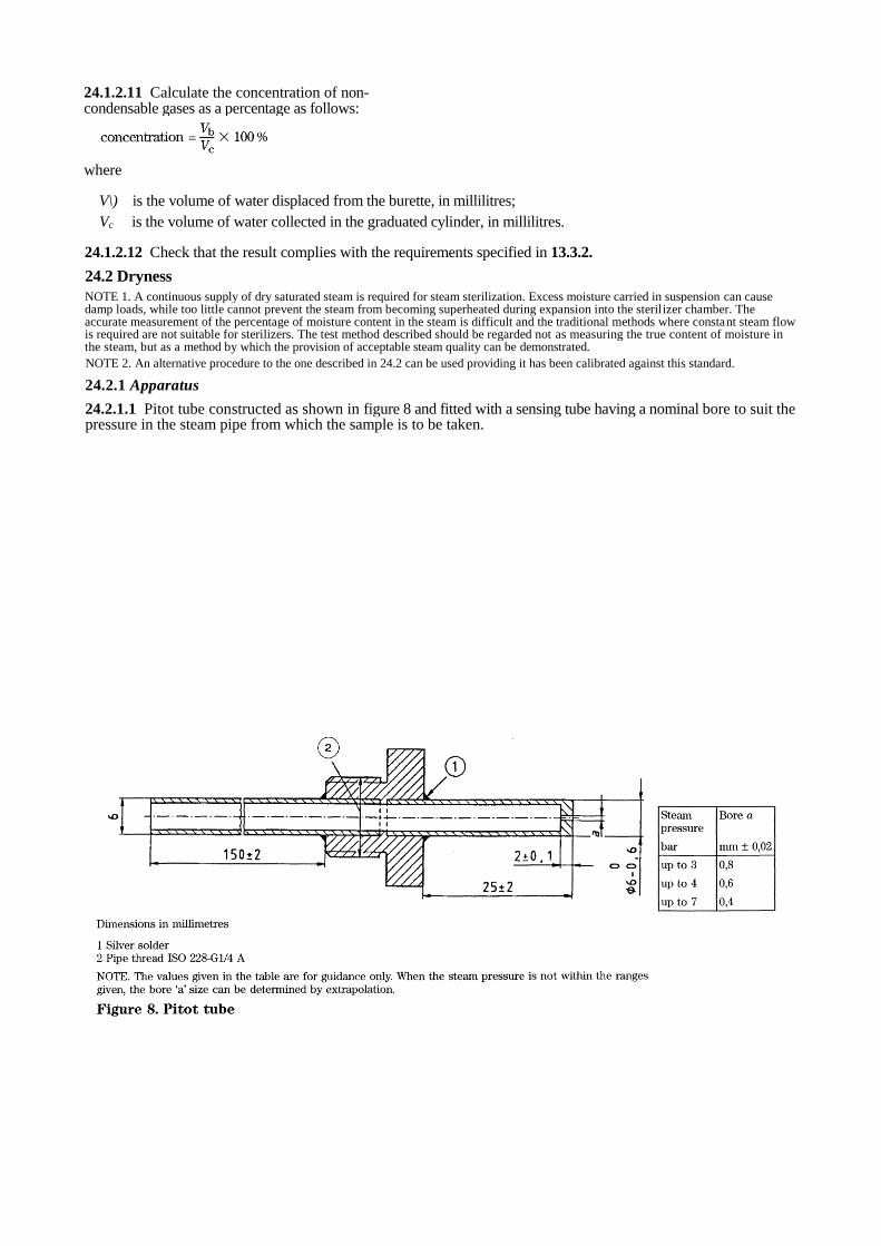
where
V\) is the volume of water displaced from the burette, in millilitres;
Vc is the volume of water collected in the graduated cylinder, in millilitres.
24.1.2.12 Check that the result complies with the requirements specified in 13.3.2.
24.2 Dryness
NOTE 1. A continuous supply of dry saturated steam is required for steam sterilization. Excess moisture carried in suspension can cause damp loads, while too little cannot prevent the steam from becoming superheated during expansion into the sterilizer chamber. The accurate measurement of the percentage of moisture content in the steam is difficult and the traditional methods where constant steam flow is required are not suitable for sterilizers. The test method described should be regarded not as measuring the true content of moisture in the steam, but as a method by which the provision of acceptable steam quality can be demonstrated. NOTE 2. An alternative procedure to the one described in 24.2 can be used providing it has been calibrated against this standard.
24.2.1 Apparatus
24.2.1.1 Pitot tube constructed as shown in figure 8 and fitted with a sensing tube having a nominal bore to suit the pressure in the steam pipe from which the sample is to be taken.
24.1.2.11 Calculate the concentration of non-condensable gases as a percentage as follows:
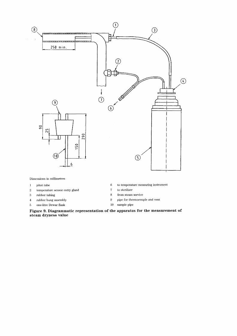
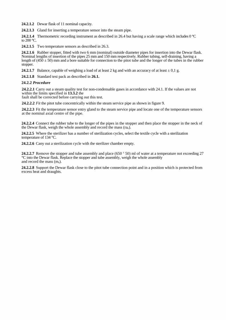
24.2.1.2 Dewar flask of 11 nominal capacity.
24.2.1.3 Gland for inserting a temperature sensor into the steam pipe.
24.2.1.4 Thermometric recording instrument as described in 26.4 but having a scale range which includes 0 °C to 200 °C.
24.2.1.5 Two temperature sensors as described in 26.3.
24.2.1.6 Rubber stopper, fitted with two 6 mm (nominal) outside diameter pipes for insertion into the Dewar flask. Nominal lengths of insertion of the pipes 25 mm and 150 mm respectively. Rubber tubing, self-draining, having a length of (450 ± 50) mm and a bore suitable for connection to the pitot tube and the longer of the tubes in the rubber stopper.
24.2.1.7 Balance, capable of weighing a load of at least 2 kg and with an accuracy of at least ± 0,1 g.
24.2.1.8 Standard test pack as described in 26.1.
24.2.2 Procedure
24.2.2.1 Carry out a steam quality test for non-condensable gases in accordance with 24.1. If the values are not within the limits specified in 13.3.2 the fault shall be corrected before carrying out this test.
24.2.2.2 Fit the pitot tube concentrically within the steam service pipe as shown in figure 9.
24.2.2.3 Fit the temperature sensor entry gland to the steam service pipe and locate one of the temperature sensors at the nominal axial centre of the pipe.
24.2.2.4 Connect the rubber tube to the longer of the pipes in the stopper and then place the stopper in the neck of the Dewar flask, weigh the whole assembly and record the mass (rae).
24.2.2.5 Where the sterilizer has a number of sterilization cycles, select the textile cycle with a sterilization temperature of 134 °C.
24.2.2.6 Cany out a sterilization cycle with the sterilizer chamber empty.
24.2.2.7 Remove the stopper and tube assembly and place (650 ± 50) ml of water at a temperature not exceeding 27 °C into the Dewar flask. Replace the stopper and tube assembly, weigh the whole assembly and record the mass (ms).
24.2.2.8 Support the Dewar flask close to the pitot tube connection point and in a position which is protected from excess heat and draughts.
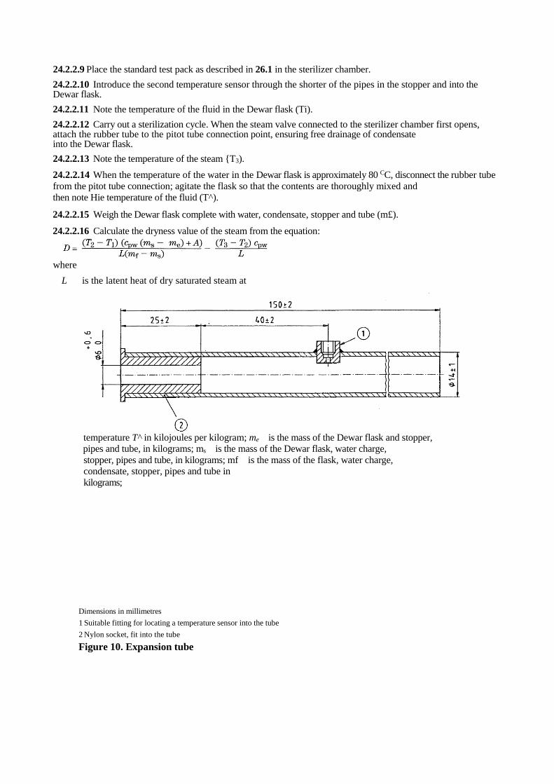
24.2.2.9 Place the standard test pack as described in 26.1 in the sterilizer chamber.
24.2.2.10 Introduce the second temperature sensor through the shorter of the pipes in the stopper and into the Dewar flask.
24.2.2.11 Note the temperature of the fluid in the Dewar flask (Ti).
24.2.2.12 Carry out a sterilization cycle. When the steam valve connected to the sterilizer chamber first opens, attach the rubber tube to the pitot tube connection point, ensuring free drainage of condensate into the Dewar flask.
24.2.2.13 Note the temperature of the steam {T3).
24.2.2.14 When the temperature of the water in the Dewar flask is approximately 80 CC, disconnect the rubber tube
from the pitot tube connection; agitate the flask so that the contents are thoroughly mixed and
then note Hie temperature of the fluid (T^).
24.2.2.15 Weigh the Dewar flask complete with water, condensate, stopper and tube (m£).
24.2.2.16 Calculate the dryness value of the steam from the equation:
where
L is the latent heat of dry saturated steam at
temperature T^ in kilojoules per kilogram; me is the mass of the Dewar flask and stopper,
pipes and tube, in kilograms; ms is the mass of the Dewar flask, water charge,
stopper, pipes and tube, in kilograms; mf is the mass of the flask, water charge,
condensate, stopper, pipes and tube in
kilograms;
Dimensions in millimetres
1 pitot tube
2 temperature sensor fitting
3 expansion tube
Figure 11. Diagrammatic representation of the apparatus for the measurement of superheat
Dimensions in millimetres
1 Suitable fitting for locating a temperature sensor into the tube
2 Nylon socket, fit into the tube
Figure 10. Expansion tube
4 to temperature measuring instrument
5 to sterilizer
6 from steam service
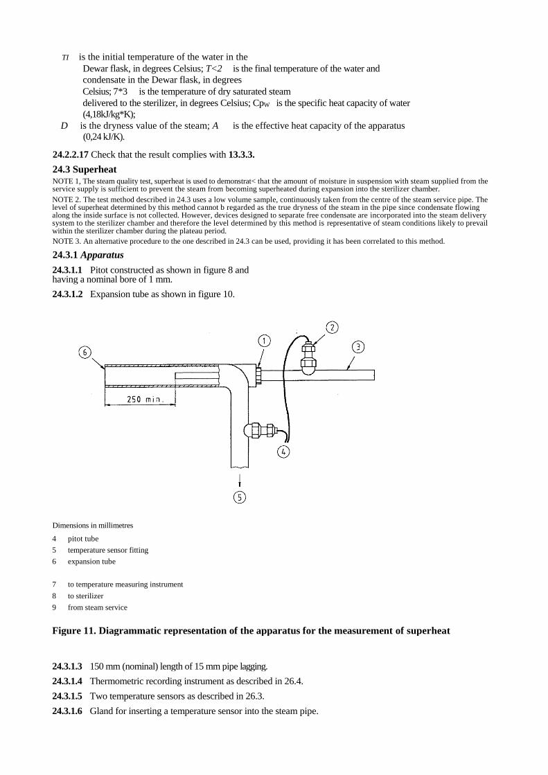
TI is the initial temperature of the water in the
Dewar flask, in degrees Celsius; T<2 is the final temperature of the water and
condensate in the Dewar flask, in degrees
Celsius; 7*3 is the temperature of dry saturated steam
delivered to the sterilizer, in degrees Celsius; CpW is the specific heat capacity of water
(4,18kJ/kg*K);
D is the dryness value of the steam; A is the effective heat capacity of the apparatus
(0,24 kJ/K).
24.2.2.17 Check that the result complies with 13.3.3.
24.3 Superheat NOTE 1, The steam quality test, superheat is used to demonstrat< that the amount of moisture in suspension with steam supplied from the service supply is sufficient to prevent the steam from becoming superheated during expansion into the sterilizer chamber.
NOTE 2. The test method described in 24.3 uses a low volume sample, continuously taken from the centre of the steam service pipe. The level of superheat determined by this method cannot b regarded as the true dryness of the steam in the pipe since condensate flowing along the inside surface is not collected. However, devices designed to separate free condensate are incorporated into the steam delivery system to the sterilizer chamber and therefore the level determined by this method is representative of steam conditions likely to prevail within the sterilizer chamber during the plateau period. NOTE 3. An alternative procedure to the one described in 24.3 can be used, providing it has been correlated to this method.
24.3.1 Apparatus
24.3.1.1 Pitot constructed as shown in figure 8 and having a nominal bore of 1 mm.
24.3.1.2 Expansion tube as shown in figure 10.
Dimensions in millimetres
4 pitot tube
5 temperature sensor fitting
6 expansion tube
7 to temperature measuring instrument
8 to sterilizer
9 from steam service
Figure 11. Diagrammatic representation of the apparatus for the measurement of superheat
24.3.1.3 150 mm (nominal) length of 15 mm pipe lagging.
24.3.1.4 Thermometric recording instrument as described in 26.4.
24.3.1.5 Two temperature sensors as described in 26.3.
24.3.1.6 Gland for inserting a temperature sensor into the steam pipe.
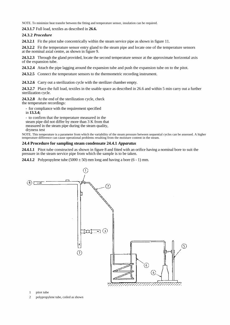
NOTE. To minimize heat transfer between the fitting and temperature sensor, insulation can be required.
24.3.1.7 Full load, textiles as described in 26.6.
24.3.2 Procedure
24.3.2.1 Fit the pitot tube concentrically within the steam service pipe as shown in figure 11.
24.3.2.2 Fit the temperature sensor entry gland to the steam pipe and locate one of the temperature sensors at the nominal axial centre, as shown in figure 9.
24.3.2.3 Through the gland provided, locate the second temperature sensor at the approximate horizontal axis of the expansion tube.
24.3.2.4 Attach the pipe lagging around the expansion tube and push the expansion tube on to the pitot.
24.3.2.5 Connect the temperature sensors to the thermometric recording instrument.
24.3.2.6 Carry out a sterilization cycle with the sterilizer chamber empty.
24.3.2.7 Place the full load, textiles in the usable space as described in 26.6 and within 5 min carry out a further sterilization cycle.
24.3.2.8 At the end of the sterilization cycle, check the temperature recordings:
- for compliance with the requirement specified in 13.3.4;
- to confirm that the temperature measured in the steam pipe did not differ by more than 3 K from that measured in the steam pipe during the steam quality, dryness test
NOTE. This temperature is a parameter from which the variability of the steam pressure between sequential cycles can be assessed. A higher temperature difference can cause operational problems resulting from the moisture content in the steam.
24.4 Procedure for sampling steam condensate 24.4.1 Apparatus
24.4.1.1 Pitot tube constructed as shown in figure 8 and fitted with an orifice having a nominal bore to suit the pressure in the steam service pipe from which the sample is to be taken.
24.4.1.2 Polypropylene tube (5000 ± 50) mm long and having a bore (6 - 1) mm.
1 pitot tube
2 polypropylene tube, coiled as shown
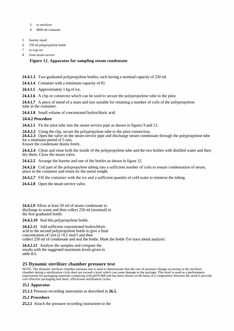
3 to sterilizer
4 8000 ml container
5 burette stand
6 250 ml polypropylene bottle
7 to trap set
8 from steam service
Figure 12. Apparatus for sampling steam condensate
24.4.1.3 Two graduated polypropylene bottles, each having a nominal capacity of 250 ml.
24.4.1.4 Container with a minimum capacity of 81.
24.4.1.5 Approximately 1 kg of ice.
24.4.1.6 A clip or connector which can be used to secure the polypropylene tube to the pitot.
24.4.1.7 A piece of metal of a mass and size suitable for retaining a number of coils of the polypropylene tube in the container.
24.4.1.8 Small volume of concentrated hydrochloric acid.
24.4.2 Procedure
24.4.2.1 Fit the pitot tube into the steam service pipe as shown in figures 9 and 12.
24.4.2.2 Using the clip, secure the polypropylene tube to the pitot connection. 24.4.2.3 Open the valve on the steam service pipe and discharge steam condensate through the polypropylene tube for a minimum period of 5 rain. Ensure the condensate drains freely.
24.4.2.4 Clean and rinse both the inside of the polypropylene tube and the two bottles with distilled water and then dry them. Close the steam valve.
24.4.2.5 Arrange the burette and one of the bottles as shown in figure 12.
24.4.2.6 Coil part of the polypropylene tubing into a sufficient number of coils to ensure condensation of steam, place in the container and retain by the metal weight.
24.4.2.7 Fill the container with the ice and a sufficient quantity of cold water to immerse the tubing.
24.4.2.8 Open the steam service valve.
24.4.2.9 Allow at least 50 ml of steam condensate to discharge to waste and then collect 250 ml (nominal) in the first graduated bottle.
24.4.2.10 Seal this polypropylene bottle.
24.4.2.11 Add sufficient concentrated hydrochloric acid to the second polypropylene bottle to give a final concentration of C(HCI) =0,1 mol/1 and then collect 250 ml of condensate and seal the bottle. Mark the bottle Tor trace metal analysis'.
24.4.2.12 Analyse the samples and compare the results with the suggested maximum levels given in table B.I.
25 Dynamic sterilizer chamber pressure test
NOTE. The dynamic sterilizer chamber pressure test is used to demonstrate that the rate of pressure change occurring in the sterilizer chamber during a sterilization cycle does not exceed a level which can cause damage to the package. This level is used as a performance requirement for packaging materials complying with prEN 868 and has been chosen on the basis of a compromise between the need to provide cost effective packaging and short, efficacious sterilization cycles.
25.1 Apparatus
25.1.1 Pressure recording instrument as described in 26.5.
25.2 Procedure
25.2.1 Attach the pressure recording instrument to the
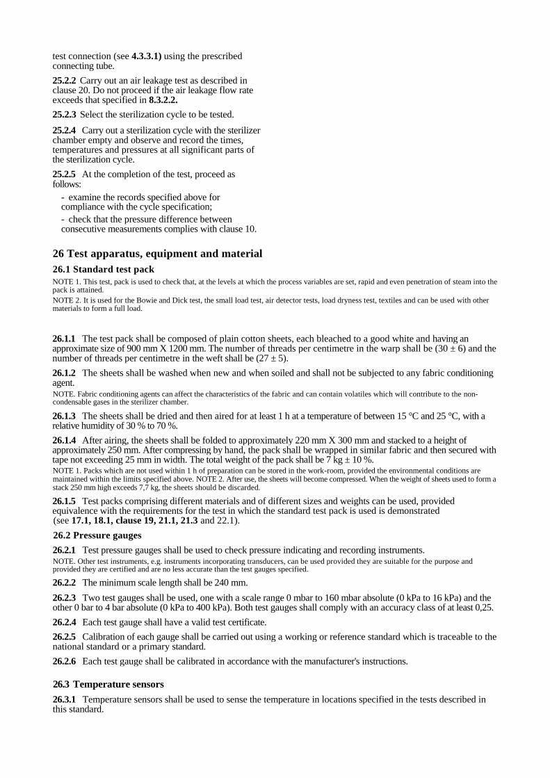
test connection (see 4.3.3.1) using the prescribed connecting tube.
25.2.2 Carry out an air leakage test as described in clause 20. Do not proceed if the air leakage flow rate exceeds that specified in 8.3.2.2.
25.2.3 Select the sterilization cycle to be tested.
25.2.4 Carry out a sterilization cycle with the sterilizer chamber empty and observe and record the times, temperatures and pressures at all significant parts of the sterilization cycle.
25.2.5 At the completion of the test, proceed as follows:
- examine the records specified above for compliance with the cycle specification;
- check that the pressure difference between consecutive measurements complies with clause 10.
26 Test apparatus, equipment and material
26.1 Standard test pack
NOTE 1. This test, pack is used to check that, at the levels at which the process variables are set, rapid and even penetration of steam into the pack is attained. NOTE 2. It is used for the Bowie and Dick test, the small load test, air detector tests, load dryness test, textiles and can be used with other materials to form a full load.
26.1.1 The test pack shall be composed of plain cotton sheets, each bleached to a good white and having an approximate size of 900 mm X 1200 mm. The number of threads per centimetre in the warp shall be (30 ± 6) and the number of threads per centimetre in the weft shall be (27 ± 5).
26.1.2 The sheets shall be washed when new and when soiled and shall not be subjected to any fabric conditioning agent. NOTE. Fabric conditioning agents can affect the characteristics of the fabric and can contain volatiles which will contribute to the non-condensable gases in the sterilizer chamber.
26.1.3 The sheets shall be dried and then aired for at least 1 h at a temperature of between 15 °C and 25 °C, with a relative humidity of 30 % to 70 %.
26.1.4 After airing, the sheets shall be folded to approximately 220 mm X 300 mm and stacked to a height of approximately 250 mm. After compressing by hand, the pack shall be wrapped in similar fabric and then secured with tape not exceeding 25 mm in width. The total weight of the pack shall be 7 kg ± 10 %. NOTE 1. Packs which are not used within 1 h of preparation can be stored in the work-room, provided the environmental conditions are maintained within the limits specified above. NOTE 2. After use, the sheets will become compressed. When the weight of sheets used to form a stack 250 mm high exceeds 7,7 kg, the sheets should be discarded.
26.1.5 Test packs comprising different materials and of different sizes and weights can be used, provided equivalence with the requirements for the test in which the standard test pack is used is demonstrated (see 17.1, 18.1, clause 19, 21.1, 21.3 and 22.1).
26.2 Pressure gauges
26.2.1 Test pressure gauges shall be used to check pressure indicating and recording instruments. NOTE. Other test instruments, e.g. instruments incorporating transducers, can be used provided they are suitable for the purpose and provided they are certified and are no less accurate than the test gauges specified.
26.2.2 The minimum scale length shall be 240 mm.
26.2.3 Two test gauges shall be used, one with a scale range 0 mbar to 160 mbar absolute (0 kPa to 16 kPa) and the other 0 bar to 4 bar absolute (0 kPa to 400 kPa). Both test gauges shall comply with an accuracy class of at least 0,25.
26.2.4 Each test gauge shall have a valid test certificate.
26.2.5 Calibration of each gauge shall be carried out using a working or reference standard which is traceable to the national standard or a primary standard.
26.2.6 Each test gauge shall be calibrated in accordance with the manufacturer's instructions.
26.3 Temperature sensors
26.3.1 Temperature sensors shall be used to sense the temperature in locations specified in the tests described in this standard.
26.3.2 Temperature sensors shall be either platinum resistance and comply with Class A of EN 60751 or thermocouple and comply with one of the tables of tolerance class 1 of EN 60584-2.
26.3.3 The major diameter of the temperature sensors used within the sterilizer chamber shall not exceed 2 mm when measured over the secondary insulation of the connecting wires.
26.3.4 The performance characteristic for the temperature sensor shall not be affected by the environment in which it is placed, e.g. pressure, steam or vacuum.
26.3.5 The temperature measured by all temperature sensors when immersed in a temperature source at a temperature known to within - 0,1 K, and within the sterilization temperature band, shall not differ by more than 0,5 K after calibration.
26.4 Thermometrie recording instrument
26.4.1 A thermometric recording instrument(s) shall be used in conjunction with temperature sensors to record the temperatures measured in the locations specified in the tests described in this standard. It can also be used to check thermometric instruments fitted to the sterilizer.
26.4.2 The recording instrument shall record the temperature from a minimum of three temperature sensors. The channels can be multiplexed or independent of each other. The sampling rate for each channel shall be 2,5 s or less. All data sampled shall be used for the interpretation of the results.
26.4.3 The scale range for analogue instruments shall include 0 °C to 150 °C. The minor mark interval shall not exceed 1 K and the chart speed shall be not less than 15 mm/min. The resolution shall not be less than 0,5 K.
26.4.4 Digital instruments shall register and record in increments of not more than 0,1 K and the scale range shall include 0 °C to 150 °C.
26.4.5 The limit of error between 0 °C and 150 °C (excluding temperature sensors) shall not exceed ± 0,25 % when tested in an ambient temperature of (20±3)°C.
26.4.6 The additional error due to the change in the environmental temperature shall not exceed 0,04 K/K.
26.4.7 Calibration shall be carried out using a working or reference standard which is traceable to the national standard or a primary standard.
26.4.8 The instrument shall have a valid test certificate.
26.4.9 The instrument shall be calibrated in accordance with the manufacturer's instructions and calibration shall include a temperature within the sterilization temperature band. When installed in the place of use, the temperature system shall be verified with an independent temperature reference source at a temperature within the sterilization temperature band.
26.4.10 The temperature reference source shall have the following features. - It shall incorporate a reference standard thermometer which is traceable to the national standard or a primary standard and shall include the range 110 °C to 140 °C. The minor mark interval shall not exceed 0,2 K - It shall incorporate a pocket, sized to accommodate a minimum of three temperature sensors as described in 26.3. The temperature gradient within the pocket shall not exceed 0,2 K and the control accuracy shall be within ± 0,1 K over the range of 100 °C to 140 °C.
26.5 Pressure recording instrument
26.5.1 A pressure recording instrument shall be used in conjunction with a pressure sensitive measuring element to record the pressure within the sterilizer chamber during a test sterilization cycle. It can also be used to check the pressure instruments) fitted to the sterilizer.
26.5.2 The instrument may be integrated into the temperature recording instrument as an additional channel calibrated for pressure. The sampling rate for each channel shall be 1 s or less. All data sampled shall be used for the interpretation of the results.
26.5.3 The scale range for analogue instruments shall include 0 bar to 4 bar absolute (0 kPa to 400 kPa). The minor mark interval shall not exceed 0,04 bar (4 kPa) and the chart speed shall be not less than 15 mm/min. The resolution shall be not less than 0,02 bar (2 kPa).
26.5.4 Digital instruments shall register and record in increments of not more than 0,01 bar (1 kPa) and the scale range shall include 0 bar to 4 bar absolute (0 kPa to 400 kPa).
26.5.5 The limit of error between 0 bar and 4 bar absolute (0 kPa to 400 kPa), the indicator and measuring system shall not exceed - 0,5 % when measured in an ambient temperature of (20 ± 3) °C.
26.5.6 The temperature coefficient of the measuring system shall not exceed 0,01 WK at the temperature at which the pressure sensor is to be used.
26.5.7 The error due to the change in the environmental temperature shall not exceed 0,02 %/K
26.5.8 The natural frequency of the sensor and connected tubing shall be not less than 10 Hz and the time constant (0 % to 63 %) for rising pressure not greater than 0,04 s.

26.5.9 The instrument shall have a valid test certificate.
26.5.10 Calibration shall be carried out using a working or reference standard which is traceable to the national standard or a primary standard.
26.5.11 The instrument, when connected to a pressure sensitive element, shall be calibrated in accordance with the manufacturer's instructions and calibration shall include a pressure within the sterilization pressure band.
26.6 Full load, textiles
NOTE. This test load is designed to represent the maximum mass of textiles which can be processed in the sterilizer and is used to demonstrate that, at the levels at which cycle variables are set, rapid and even penetration of steam into the centre of a load occurs and the sterilizing condition is achieved.
26.6.1 The full load shall comprise folded sheets and a standard test pack as described in 26.1.
26.6.2 Each sheet shall contain at least 50 % m/m of cotton fibre and have a mass per unit area of approximately 200 g/m2. The sheets shall be laundered when new or soiled and not subjected to any fibre conditioning agent (see 26.1).
26.6.3 The sheets shall be dried and then aired for at least 1 h at a temperature of between 15 °C and 25 °C and at a relative humidity 30 % to 70 %.
26.6.4 After airing, the sheets shall be folded and laid one on top of the other to form a stack with a base area of approximately 250 mm X 500 mm and a mass of (7,5 ±0,5) kg. NOTE. Stacks which are not used within 1 h of preparation can be stored in the work room provided the environmental conditions are maintained within the limits specified above.
26.6.5 The standard test pack shall be located within the sterilizer chamber, and in a position identified by the manufacturer as the most difficult to sterilize. The remainder of the usable space shall be loaded with stacks of sheets each with the layers of fabric in the baskets dimensionaUy similar to one sterilization module, or they can be loose within the sterilizer chamber.
26.6.6 The mass of fabric in the test load shall be equivalent to (7,5 ± 0,5) kg per load module.
26.7 Test pack, rubber
NOTE. This test pack is used to represent a unit of rubber objects, e.g. tubing, in which specified sterilizing conditions are difficult to achieve.
26.7.1 The test pack, rubber shall comprise a stack of packages 100 mm high and occupying a volume equivalent to half of a sterilization module. Within this stack of packages three packages shall contain test pieces as described below and the remaining packages shall contain a piece of natural rubber tubing having a nominal size of 1500 mm length, 5 mm outside diameter and 3 mm inside diameter. The rubber tubing shall be coiled in the same plane into a spiral. All packages shall be double-wrapped in size 90 plastic paper bags complying with prEN 868-5, with the paper of each bag on the same side.
26.7.2 Each test piece shall comprise three inoculated carriers complying with prEN 866-3, (consisting of a carrier of glass tubing of nominal dimensions, external diameter 4,0 mm, internal diameter 2,5 mm and length 45 mm) inserted as spigots to rejoin a piece of natural rubber tubing of nominal size 1500 mm length, 5 mm outside diameter, 3 mm inside diameter. One inoculated carrier shall be located in the middle of the tubing and one approximately 200 mm from each end of the tubing.
26.7.3 The stack of packages shall be assembled with the paper side of each package facing downwards and the three packages containing the test pieces shall be located within the stack at nominal heights of 25 mm, 50 mm and 75 mm. NOTE. The stack should be supported, for example, by a wire mesh basket.
26.7.4 Allow the stack to equilibrate for at least 1 h at a temperature of between 15 °C and 25 °C at a relative humidity 30 % to 70 %.
26.7.5 Store the test pack until required in an environment maintained within the limits specified above.
26.8 Test pack, metal
NOTE. This test pack is used to represent a unit of metal objects, e.g. instruments, which is difficult to dry.
26.8.1 Sterilizer load shall comprise a test box containing a wire mesh basket and a quantity of metal screws wrapped in textile material
26.8.2 The test box shall:
- have a sealed lid and comply with the detail given in figure 13;
- not have additional holes to those shown in figure 13;
- be constructed from 1 mm (nominal) thick austenitic stainless steel according to EN 10088-2;
- have a mass of 4,2 kg ± 0,2 kg.
26.8,3 The wire mesh basket shall:
- be constructed from austenitic stainless steel according to EN 10088-3;
- have a nominal grid size on the base of 5mm X 5mm;
- have a nominal grid size on the sides of 5 mm X 5 mm;
- have a load surface separated from the support surface by approximately 6 mm;
- be capable of supporting an evenly distributed load of 10 kg;
- have external dimensions of length (480 ± 5) mm, width (254 _°4) mm and height (50+^) mm;
- have a mass of (1,3 - 0,1) kg.
26.8.4 The metal screws used in the test load shall:
- be austenitic stainless steel according to EN 100884;
- be hexagon head screws ISO 4017-M12 X 100;
- have a total mass of (8,6 ± 0,1) kg;
- be cleaned, degreased and dried.
26.8.5 The textile material used in the test shall:
- be a plain cotton sheet, bleached to a good white and having an approximate size of 900 mm X 1200 mm; the number of threads per centimetre in the warp shall be (30 ± 6) and the number of threads per centimetre in the weft (27 ± 5);
- be washed when new and when soiled and not subjected to any fabric conditioning agent, dried and aired.
26.8.6 All items used to form the test pack shall be stored for at least 1 h at a temperature of between 15 °C and 25 °C at a relative humidity 30 % to 70%. NOTE. This requirement assumes that before packaging, components have not been allowed to equilibrate to the local environment.
The test pack shall be assembled as follows: *- place the wire mesh basket onto the sheet;
- distribute the screws evenly in the wire mesh basket;
- fold the sheet over the wire mesh basket containing the screws;
~ place the wrapped wire mesh basket into the tray.
26.8.7 Store the test pack until required in an environment maintained within the limits specified for the items used to form the test pack.
26.9 Metering device
NOTE. A metering device is used to admit air to the sterilizer chamber to test that a process monitoring device will indicate when the mass of air present in the sterilizer chamber is sufficient for the sterilization cycle to be of uncertain efficacy.
26.9.1 The device shall be capable of controlling the flow of air into an evacuated sterilizer chamber.
26.9.2 The device shall be adjustable and have a range which includes a flow equivalent to 0 ml/min-1 to 5 ml/min-1 of the sterilizer chamber.
26.9.3 The error in repeatability between 10 % and 90 % of the setting range shall not exceed ± 5 %.
27 Documentation
27.1 Records of tests and checks sufficient to assure the purchaser that the sterilizer has been manufactured in accordance with the specification shall be provided (see also 28.3).
27.2 The documentation shall include:
- evidence of verification of the calibration of all instrumentation;
- test certificates and details of markings for all pressure vessels;
- certification that the function of each safety device and its setting complies with the specification;
- details of the settings of the automatic controller together with pressures, temperatures and times taken for each significant part of the sterilization cycle, e.g. change from each stage or sub-stage;
- when specified in the contract (see 15.3) the supplier shall provide evidence of compliance with the installation test;
- the setting of the air detector if one is fitted;
- declaration of compliance with the type test and works test (see clause 16 and table 4). NOTE. This documentation is normally retained by the user in a validation file and is required before the commencement of commissioning and performance qualification studies as required by EN 554.
28 Information
28.1 The objective of clause 28 is to enable the purchaser to prepare for installation, to install and operate the sterilizer and to perform routine maintenance.
The information specified in 28.2, 28.3 and 28.4 shall be provided either in one part, prior to delivery of the sterilizer or in two parts, prior to delivery and at delivery.
28.2 Before delivery of the sterilizer and with a view to its installation, the sterilizer manufacturer shall provide the purchaser with the following information:
a) installation instructions, including the overall dimensions and overall mass of the sterilizer, the floor loading at each support when the sterilizer pressure vessel is filled with water, the clearance required for access and the masses of the principal heavy components;
b) type of electricity supply, e.g. DC or AC, single or three phase, voltage and frequency including minimum and maximum values and maximum continuous power in kilowatts or Mlovolt amperes; c) the maximum flow and usage rate and the maximum and minimum supply pressure for steam;
d) the minimum and maximum pressure and flow at minimum pressure, volume used per cycle for water and feed water; e) the minimum and maximum pressure and flow at minimum pressure for compressed air; f) the total heat in watts transmitted to the surrounding air when the sterilizer is operated in an ambient temperature of (23 ± 2) °C in still air;
NOTE. When designing the ventilation system the user should take into account the heat transmitted by the sterilized load.
g) the heat in watts transmitted from the facia when the sterilizer is operated in an ambient temperature of (23 ± 2) °C in the working area and 50 °C (nominal) in the casing and the door(s) are closed; h) the mean and peak sound power levels generated by the sterilizer, expressed as an A-weighted sound power level;
j) the type of doors and information on the necessary space required for the movement of the door(s); k) the acceptable range of steam supply pressures;
1) the approximate location of the reference
measurement point of the sterilizer chamber;
NOTE. If requested, documentary evidence to show the relationship between the coolest part of the sterilizer chamber and the reference measurement point.
m) the maximum flow of water and condensed
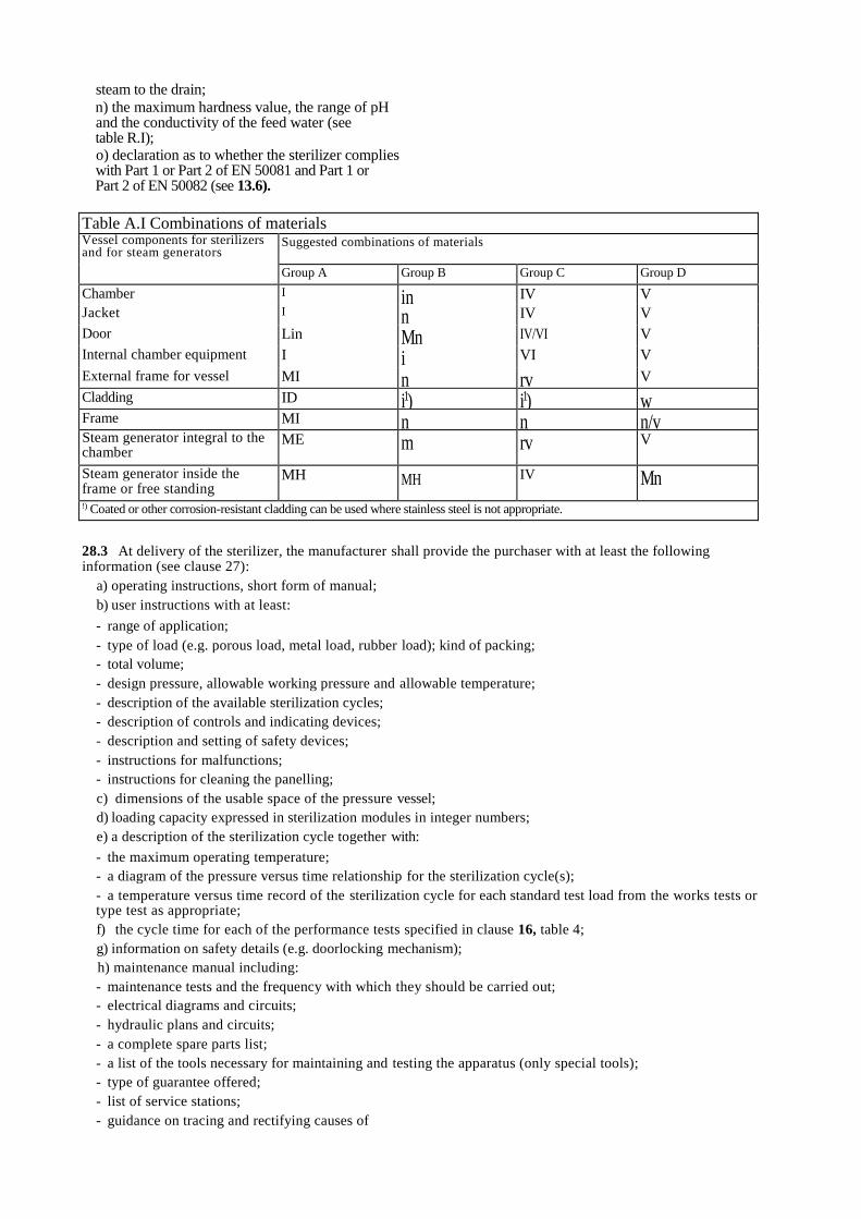
steam to the drain;
n) the maximum hardness value, the range of pH and the conductivity of the feed water (see table R.I); o) declaration as to whether the sterilizer complies with Part 1 or Part 2 of EN 50081 and Part 1 or Part 2 of EN 50082 (see 13.6).
Table A.I Combinations of materials Vessel components for sterilizers and for steam generators
Suggested combinations of materials
Group A Group B Group C Group D
Chamber I in IV V
Jacket I n IV V
Door Lin Mn IV/VI V
Internal chamber equipment I i VI V
External frame for vessel MI n rv V
Cladding ID i1) i1) w Frame MI n n n/v Steam generator integral to the chamber
ME m rv V
Steam generator inside the frame or free standing
MH MH IV Mn
!) Coated or other corrosion-resistant cladding can be used where stainless steel is not appropriate.
28.3 At delivery of the sterilizer, the manufacturer shall provide the purchaser with at least the following information (see clause 27):
a) operating instructions, short form of manual;
b) user instructions with at least:
- range of application;
- type of load (e.g. porous load, metal load, rubber load); kind of packing;
- total volume;
- design pressure, allowable working pressure and allowable temperature;
- description of the available sterilization cycles;
- description of controls and indicating devices;
- description and setting of safety devices;
- instructions for malfunctions;
- instructions for cleaning the panelling;
c) dimensions of the usable space of the pressure vessel;
d) loading capacity expressed in sterilization modules in integer numbers;
e) a description of the sterilization cycle together with:
- the maximum operating temperature;
- a diagram of the pressure versus time relationship for the sterilization cycle(s);
- a temperature versus time record of the sterilization cycle for each standard test load from the works tests or type test as appropriate;
f) the cycle time for each of the performance tests specified in clause 16, table 4;
g) information on safety details (e.g. doorlocking mechanism);
h) maintenance manual including:
- maintenance tests and the frequency with which they should be carried out;
- electrical diagrams and circuits;
- hydraulic plans and circuits;
- a complete spare parts list;
- a list of the tools necessary for maintaining and testing the apparatus (only special tools);
- type of guarantee offered;
- list of service stations;
- guidance on tracing and rectifying causes of
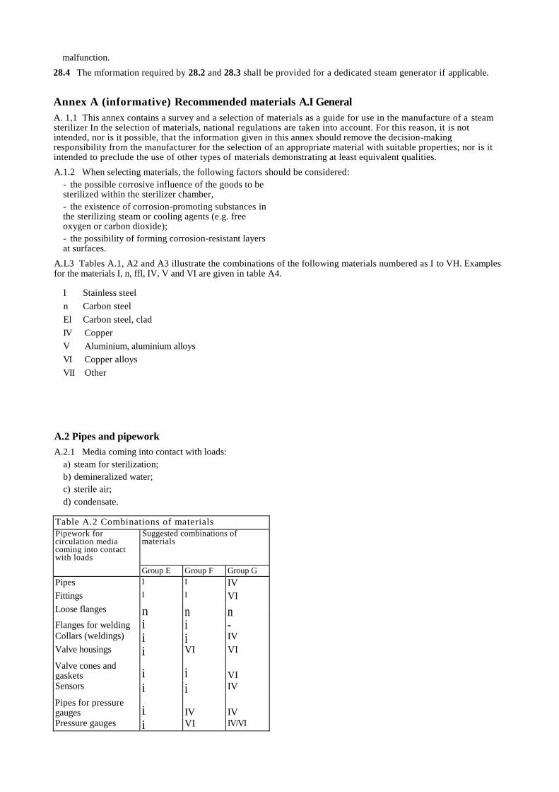
malfunction.
28.4 The mformation required by 28.2 and 28.3 shall be provided for a dedicated steam generator if applicable.
Annex A (informative) Recommended materials A.I General
A. 1,1 This annex contains a survey and a selection of materials as a guide for use in the manufacture of a steam sterilizer In the selection of materials, national regulations are taken into account. For this reason, it is not intended, nor is it possible, that the information given in this annex should remove the decision-making responsibility from the manufacturer for the selection of an appropriate material with suitable properties; nor is it intended to preclude the use of other types of materials demonstrating at least equivalent qualities.
A.1.2 When selecting materials, the following factors should be considered:
- the possible corrosive influence of the goods to be sterilized within the sterilizer chamber,
- the existence of corrosion-promoting substances in the sterilizing steam or cooling agents (e.g. free oxygen or carbon dioxide);
- the possibility of forming corrosion-resistant layers at surfaces.
A.L3 Tables A.1, A2 and A3 illustrate the combinations of the following materials numbered as I to VH. Examples for the materials I, n, ffl, IV, V and VI are given in table A4.
I Stainless steel
n Carbon steel
El Carbon steel, clad
IV Copper
V Aluminium, aluminium alloys
VI Copper alloys
VII Other
A.2 Pipes and pipework
A.2.1 Media coming into contact with loads:
a) steam for sterilization;
b) demineralized water;
c) sterile air;
d) condensate.
Table A.2 Combinations of materials
Pipework for circulation media coming into contact with loads
Suggested combinations of materials
Group E Group F Group G
Pipes I I IV
Fittings I I VI
Loose flanges n n n
Flanges for welding i i - Collars (weldings) i i IV
Valve housings i VI VI
Valve cones and gaskets i i VI Sensors i i IV
Pipes for pressure gauges i IV IV
Pressure gauges i VI IV/VI
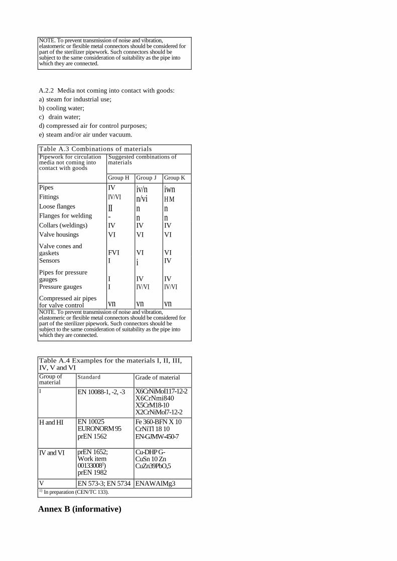
NOTE. To prevent transmission of noise and vibration, elastomeric or flexible metal connectors should be considered for part of the sterilizer pipework. Such connectors should be subject to the same consideration of suitability as the pipe into which they are connected.
A.2.2 Media not coming into contact with goods:
a) steam for industrial use;
b) cooling water;
c) drain water;
d) compressed air for control purposes;
e) steam and/or air under vacuum.
Table A.3 Combinations of materials
Pipework for circulation media not coming into contact with goods
Suggested combinations of materials
Group H Group J Group K
Pipes IV iv/n iwn Fittings IV/VI n/vi H M Loose flanges II n n Flanges for welding - n n Collars (weldings) IV IV IV
Valve housings VI VI VI
Valve cones and gaskets FVI VI VI Sensors I i IV
Pipes for pressure gauges I IV IV
Pressure gauges I IV/VI IV/VI
Compressed air pipes for valve control vn vn vn NOTE. To prevent transmission of noise and vibration, elastomeric or flexible metal connectors should be considered for part of the sterilizer pipework. Such connectors should be subject to the same consideration of suitability as the pipe into which they are connected.
Table A.4 Examples for the materials I, II, III, IV, V and VI
Group of material
Standard Grade of material
I EN 10088-1, -2, -3 X6CrNiMoI117-12-2 X6CrNmi840 X5CrM18-10 X2CrNiMol7-12-2
H and HI EN 10025 EURONORM 95
prEN 1562
Fe 360-BFN X 10 CrNiTl 18 10
EN-GJMW-450-7
IV and VI prEN 1652; Work item 001330081) prEN 1982
Cu-DHP G-CuSn 10 Zn CuZn39PbO,5
V EN 573-3; EN 5734 ENAWAlMg3 1} In preparation (CEN/TC 133).
Annex B (informative)
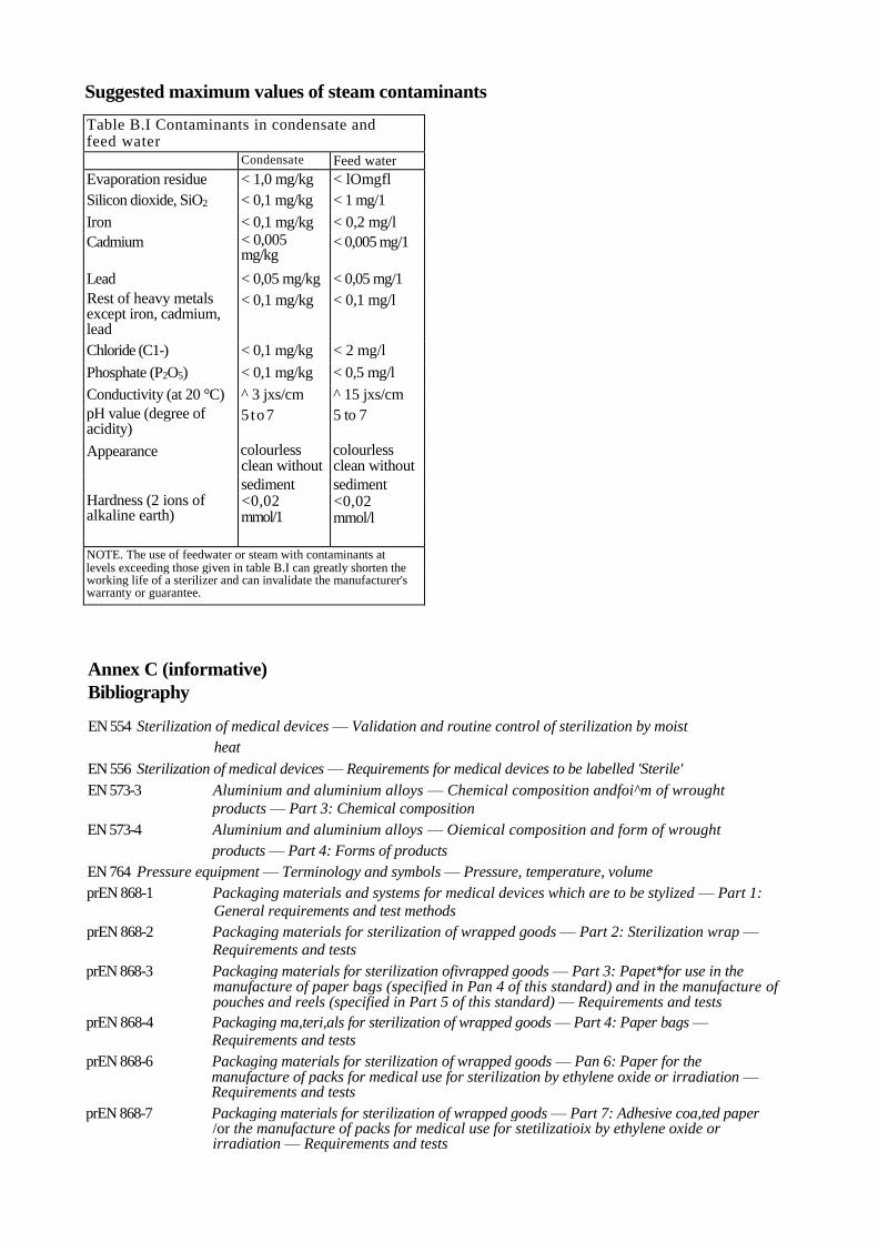
Suggested maximum values of steam contaminants
Table B.I Contaminants in condensate and feed water
Condensate Feed water
Evaporation residue < 1,0 mg/kg < lOmgfl
Silicon dioxide, SiO2 < 0,1 mg/kg < 1 mg/1
Iron < 0,1 mg/kg < 0,2 mg/l
Cadmium < 0,005 mg/kg
< 0,005 mg/1
Lead < 0,05 mg/kg < 0,05 mg/1
Rest of heavy metals except iron, cadmium, lead
< 0,1 mg/kg < 0,1 mg/l
Chloride (C1-) < 0,1 mg/kg < 2 mg/l
Phosphate (P2O5) < 0,1 mg/kg < 0,5 mg/l
Conductivity (at 20 °C) ^ 3 jxs/cm ^ 15 jxs/cm
pH value (degree of acidity)
5to7 5 to 7
Appearance colourless clean without
colourless clean without
sediment sediment Hardness (2 ions of alkaline earth)
<0,02 mmol/1
<0,02 mmol/l
NOTE. The use of feedwater or steam with contaminants at levels exceeding those given in table B.I can greatly shorten the working life of a sterilizer and can invalidate the manufacturer's warranty or guarantee.
Annex C (informative)
Bibliography
EN 554 Sterilization of medical devices — Validation and routine control of sterilization by moist
heat
EN 556 Sterilization of medical devices — Requirements for medical devices to be labelled 'Sterile'
EN 573-3 Aluminium and aluminium alloys — Chemical composition andfoi^m of wrought
products — Part 3: Chemical composition
EN 573-4 Aluminium and aluminium alloys — Oiemical composition and form of wrought
products — Part 4: Forms of products
EN 764 Pressure equipment — Terminology and symbols — Pressure, temperature, volume
prEN 868-1 Packaging materials and systems for medical devices which are to be stylized — Part 1:
General requirements and test methods
prEN 868-2 Packaging materials for sterilization of wrapped goods — Part 2: Sterilization wrap —
Requirements and tests
prEN 868-3 Packaging materials for sterilization ofivrapped goods — Part 3: Papet*for use in the manufacture of paper bags (specified in Pan 4 of this standard) and in the manufacture of pouches and reels (specified in Part 5 of this standard) — Requirements and tests
prEN 868-4 Packaging ma,teri,als for sterilization of wrapped goods — Part 4: Paper bags —
Requirements and tests
prEN 868-6 Packaging materials for sterilization of wrapped goods — Pan 6: Paper for the manufacture of packs for medical use for sterilization by ethylene oxide or irradiation — Requirements and tests
prEN 868-7 Packaging materials for sterilization of wrapped goods — Part 7: Adhesive coa,ted paper /or the manufacture of packs for medical use for stetilizatioix by ethylene oxide or irradiation — Requirements and tests
prEN 868-8 Packaging mateii,als for sterilization ofivrapped goods — Part 8: Re-usable sterilization
containers — Requirements and tests
prEN 1562 Founding — Malleable cast irons
prEN 1652 Copper and copper alloys — Plate, sheet, strip and circles for general purposes
prEN 1982 Copper and copper alloys — Ingots and castings
EN 10025 : 1993 Hot-rolled products of non-alloy structural steels — Technical delivery conditions (includes amendment Al : 1993)
EN ISO 9001 : 1994 Quality systems — Model for quality assurance in design/development, production, installation and servicing (ISO 9001 : 1994)
EN ISO 9002 Quality systems — Model for quality assurance in production, installation and set~vicing
(ISO 9002 : 1994)
EN ISO 9004-1 Quality management and quality system elements — Part 1: Guidelines
(ISO 9004-1 : 1994)
EN 46001 Quality systems — Medical devices — Particular requirements for the application of
EN 29001
EN 46002 Quality systems — Medical, devices — Particular requirements for the application of EN 29002
EURONORM 95 Heat-resistance steels — Technical terms of delivery Work item in preparation by CEN/TC 133 00133008
Compliance should be tested in accordance with acknowledged analytical methods. A method by which a sample of
condensate can be taken is given in 24.4.
List of references
Annex ZA (informative)
Clauses of this European Standard addressing essential requirements or other provisions of EU Directives
This European Standard has been prepared under a mandate given to CEN/CENELEC by the European Commission and the European Free Trade Association and supports essential requirements of EU Directive 93/42/EEC.
WARNING: Other requirements and other EU Directives may by applicable to the product(s) falling within the scope of this standard.
The following clauses of this standard as detailed in table ZA.1 are likely to support requirements of the Directive 93/42/EEC.
Compliance with the clauses of this standard provides one means of conforming with the specific essential requirements of the Directives concerned and associated EFTA regulations.
See national foreword.
Table ZA.l Correspondence between this European Standard and EU Directives Clauses/subclauses of this European Standard
Corresponding ERs of Directive 93/42/EEC
Remarks
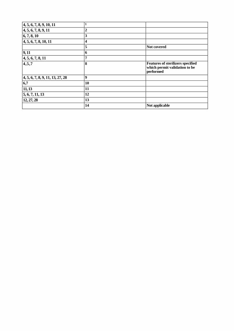
4, 5, 6, 7, 8, 9, 10, 11 1
4, 5, 6, 7, 8, 9, 11 2
6, 7, 8, 10 3
4, 5, 6, 7, 8, 10, 11 4
5 Not covered
9, 11 6
4, 5, 6, 7, 8, 11 7
4,5,7 8 Features of sterilizers specified which permit validation to be performed
4, 5, 6, 7, 8, 9, 11, 13, 27, 28 9
6,7 10
11, 13 11
5, 6, 7, 11, 13 12
12, 27, 28 13
14 Not applicable

BSI — British Standards Institution
BSI is the independent national body responsible for preparing British Standards. It presents the UK view on standards in Europe and at the international level. It is incorporated by Royal Charter.
Revisions
British Standards are updated by amendment or revision. Users of British Standards should make sure that they possess the latest amendments or editions.
It is the constant aim of BSI to improve the quality of our products and services. We would be grateful if anyone finding an inaccuracy or ambiguity while using this British Standard would inform the Secretary of the technical committee responsible, the identity of which can be found on the inside front cover. Tel: 020 8996 9000. Fax: 020 8996 7400.
BSI offers members an individual updating service called PLUS which ensures that subscribers automatically receive the latest editions of standards.
Buying standards
Orders for all BSI, international and foreign standards publications should be addressed to Customer Services. Tel: 020 8996 9001. Fax: 020 8996 7001.
In response to orders for international standards, it is BSI policy to supply the BSI implementation of those that have been published as British Standards, unless otherwise requested.
Information on standards
BSI provides a wide range of information on national, European and international standards through its Library and its Technical Help to Exporters Service. Various BSI electronic information services are also available which give details on all its products and services. Contact the Information Centre. Tel: 020 8996 7111. Fax: 020 8996 7048.
Subscribing members of BSI are kept up to date with standards developments and receive substantial discounts on the purchase price of standards. For details of these and other benefits contact Membership Administration. Tel: 020 8996 7002. Fax: 020 8996 7001.
Copyright
Copyright subsists in all BSI publications. BSI also holds the copyright, in the UK, of the publications of the international standardization bodies. Except as permitted under the Copyright, Designs and Patents Act 1988 no extract may be reproduced, stored in a retrieval system or transmitted in any form or by any means - electronic, photocopying, recording or otherwise - without prior written permission from BSI.
This does not preclude the free use, in the course of implementing the standard, of necessary details such as symbols, and size, type or grade designations. If these details are to be used for any other purpose than implementation then the prior written permission of BSI must be obtained.
If permission is granted, the terms may include royalty payments or a licensing agreement Details and advice can be obtained from the Copyright Manager. Tel: 020 8996 7070.