Embed Size (px)
DESCRIPTION
vertical grazing manual
Citation preview
BRITISH STANDARD BS 5516:1991
Code of practice for
Design and installation of sloping and vertical patent glazing

BS 5516:1991
This British Standard, having been prepared under the direction of the Elements and Components (of Diverse Materials) for Buildings Standards Policy Committee, was published under the authority of the Standards Board and comes into effect on30 April 1991
© BSI 04-1999
First published, as CP145.101. April 1951Second edition, as CP145-1, January 1969Third edition, as BS 5516, December 1977Fourth edition April 1991
The following BSI references relate to the work on this standard:Committee reference ECB/25Draft for comment 89/11294 DC
ISBN 0 580 19167 2
Committees responsible for this British Standard
The preparation of this British Standard was entrusted by the Elements and Components (of Diverse Materials) for Buildings Standards Policy Committee (ECB/-) to Technical Committee ECB/25, upon which the following bodies were represented:
Flat Glass Manufacturers’ AssociationGlass and Glazing FederationInstitution of Structural EngineersPatent Glazing Contractors’ AssociationRoyal Institute of British ArchitectsRoyal Institution of Chartered Surveyors
Amendments issued since publication
Amd. No. Date Comments
BS 5516:1991
© BSI 04-1999 i
Contents
PageCommittees responsible Inside front coverForeword iiiSection 1. General0 Introduction 11 Scope 12 Definitions 13 Provision of information 3Section 2. Components, materials and finishes4 General 45 Supporting members, flashings, ancillary components and finishes 46 Infillings 77 Sealing and glazing materials 8Section 3. Design8 General 99 Selection of materials 910 Structural 911 Openings 3412 Fire 3513 Weather resistance 3514 Heat conservation 3615 Condensation 3716 Solar heat gain 3717 Thermal safety 4018 Transmission of light 4019 Sound reduction 4120 Durability 4121 Human safety 4222 Security 4423 Access for maintenance and cleaning 44Section 4. Work on site24 Storage of materials 4525 Installation 45Section 5. Maintenance26 Access for maintenance and cleaning 4927 Inspection 4928 Cleaning 4929 Other maintenance 51Appendix A Symbols 52Appendix B Wind load 53Appendix C Snow load 53Appendix D Dead load (self-weight) 54Appendix E Maintenance load 54Appendix F Determination of working pressures for patent glazing 54Appendix G Determination of working pressures for supporting members 55Appendix H Determination of required geometric properties of section for supporting members 56Appendix J Plastics glazing sheet materials 57
BS 5516:1991
ii © BSI 04-1999
PageAppendix K Thermal stress in glass 61Figure 1 — Aluminium patent glazing bars 5Figure 2 — Recommended minimum thicknesses of glass for infilling 18Figure 2(a) — Two-edge supported annealed glass (float, cast, polished wired and wired cast) 18Figure 2(b) — Two-edge supported toughened (tempered) float glass 19Figure 2(c) — Two-edge supported laminated float glass 20Figure 2(d) — Two-edge supported double glazing units (symmetrical) (float and toughened (tempered) float) 21Figure 2(e) — Two-edge supported double glazing units (asymmetrical) (float, cast, toughened (tempered) float, laminated float, polished wired and wired cast) 22Figure 2(f) — Four-edge supported annealed glass (float, cast, polished wired and wired cast) 23Figure 2(g) — Four-edge supported toughened (tempered) float glass 24Figure 2(h) — Four-edge supported laminated float glass 25Figure 2(i) — Four-edge supported double glazing units (symmetrical) (annealed float glass) 26Figure 2(j) — Four-edge supported double glazing units (symmetrical) (laminated float and toughened (tempered) float) 27Figure 2(k) — Four-edge supported double glazing units (asymmetrical) (toughened (tempered) float and laminated float) 28Figure 2(l) — Four-edge supported double glazing units (asymmetrical) (float, laminated float, polished wired and wired cast) 29Figure 2(m) — Four-edge supported double glazing units (asymmetrical) (cast, polished wired and wired cast) 30Figure 3 — Recommended minimum thicknesses of solid plastics glazing sheet material for infilling 31Figure 3(a) — Two-edge supported panes and four-edge supported panes with aspect ratios of pane greater than 3.5 : 1 31Figure 3(b) — Four-edge supported panes with aspect ratios of pane from 2.5 : 1 to 3.5 : 1 32Figure 3(c) — Four-edge supported panes with aspect ratios of pane from 1.5 : 1 to 2.5 : 1 33Figure 3(d) — Four-edge supported panes with aspect ratios of pane from 1.0 : 1 to 1.5 : 1 34Figure 4 — Additional framing at entrances 36Figure 5 — Typical rack for the storage of glass 46Figure 6 — Dimensional and positional tolerances of patent glazing 47Figure 7 — Use of ladders and crawling boards for temporary access 50Figure 8 — Edge clearance and edge cover for plastics glazing sheet materials 59Figure 9 — Cutting hollow section plastics glazing sheet materials 60Table 1 — Fire performance of glass 35Table 2 — Thermal transmittance (U-values) of glass (single glass and sealed double glazing units) 38Table 3 — Thermal transmittance (U-values) of plastics glazing sheet materials (single and double sheet and hollow section) 38Publications referred to 62
BS 5516:1991
© BSI 04-1999 iii
Foreword
This British Standard has been prepared under the direction of the Elements and Components (of Diverse Materials) for Buildings Standards Policy Committee. It is a revision of BS 5516:1977, which is withdrawn.This edition gives recommendations for the use of plastics glazing sheet materials as infilling and contains more detailed advice about the structural design of patent glazing. Subjects not previously dealt with and now included are human safety, security, thermal safety and finishes of materials.Assessed capability. Users of this British Standard are advised to consider the desirability of assessment and registration of a supplier’s quality systems against the appropriate Part of BS 5750 by a third party certification body.A British Standard does not purport to include all the necessary provisions of a contract. Users of British Standards are responsible for their correct application.
Compliance with a British Standard does not of itself confer immunity from legal obligations.
Summary of pagesThis document comprises a front cover, an inside front cover, pages i to iv, pages 1 to 62, an inside back cover and a back cover.This standard has been updated (see copyright date) and may have had amendments incorporated. This will be indicated in the amendment table onthe inside front cover.
iv blank
BS 5516:1991
© BSI 04-1999 1
Section 1. General
0 IntroductionPatent glazing is the term applied to a self-draining and ventilated system of dry glazing which does not rely necessarily for its watertightness upon external glazing seals. It consists essentially of a series of longitudinal supporting members, i.e. patent glazing bars, and an infilling of glass or other suitable infill material. Patent glazing bars are attached to and supported by structural members, either directly or indirectly, but are not usually connected together in the form of a frame.Patent glazing systems are described by the number of edges by which the infilling is supported by the supporting members.
a) Two-edge systems are those in which the infilling is fully supported by patent glazing bars on two opposite longitudinal edges only. Horizontal flashings or other weatherings are normally provided at the top and bottom edges and between panes.b) Four-edge systems are those in which the infilling is fully supported by patent glazing bars on two opposite longitudinal edges and additionally on the other two edges by transverse supporting members.
1 ScopeThis standard gives recommendations for the design, manufacture, installation and maintenance of sloping and vertical patent glazing systems attached to and supported by structural members of adequate strength, stiffness and stability. All the recommendations apply to flat, including faceted, patent glazing. The recommendations also apply to curved patent glazing except for the structural design of curved patent glazing.The patent glazing systems included in this standard comprise supporting members of aluminium or steel for two-edge and four-edge systems for single and double glazing, and other components. A range of transparent and opaque infillings of glass, plastics glazing sheet and other materials is included; specific information on plastics glazing sheet materials is given in Appendix J.This standard covers the use of patent glazing in permanent buildings and structures, other than greenhouses. Clauses which are relevant also apply to the use of patent glazing inside buildings.The procedure for structural design given in this standard is based on permissible stress design. Limit state design may be used but is not included in this standard.
This standard does not include the design of the supporting structure to which the patent glazing is attached.NOTE The titles of the publications referred to in this standard are listed on page 62.
2 DefinitionsFor the purposes of this British Standard the following definitions apply, together with the symbols in Appendix A.
2.1 aspect ratio of pane
ratio of the longer to the shorter side of a rectangular pane
2.2 butt joint
joint between edges of adjacent panes of infilling, usually horizontal and weathered by a came or sealant
2.3 came
non-loadbearing member used to weather a horizontal butt joint in a two-edge system of patent glazing
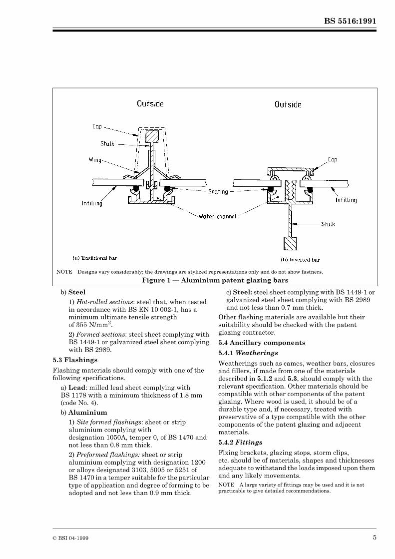
2.4 cap
strip, which may retain infilling, fitted over a patent glazing bar to impede direct water penetration (See Figure 1)
2.5 fastener
mechanical device for securing patent glazing to the supporting structure, or for connecting or fastening one part to another
2.6 fixing
item or assembly of items which forms the attachment of patent glazing to the supporting structure
2.7 fixing bracket
fitting attached to a patent glazing bar and secured to a structural member by fastenersNOTE Cleat, plate, shoe and slipper are deprecated terms for fixing bracket.
2.8 flashing
strip of impervious material, usually metal, dressed or fitted in order to exclude water from the junction between patent glazing and adjacent material or between joints in patent glazing
BS 5516:1991
2 © BSI 04-1999
2.9 four-edge system
patent glazing with infilling fully supported on four edges
2.10 glazing stop
fitting attached to the lower end of a patent glazing bar to prevent the infilling from sliding
2.11 head
top member in patent glazing, usually horizontal
2.12 infilling
sheet material that occupies the space between supporting members
2.13 pane
infilling cut to size and shape
2.14 patent glazing bar
longitudinal supporting member in patent glazing that spans between structural members and incorporates water channels
2.15 setting blocks
pieces of resilient material used at the bottom edge of infilling
2.16 sill
bottom member in patent glazing, usually horizontal
2.17 sloping patent glazing
patent glazing at an angle of less than 75° to the horizontal
2.18 spacing
perpendicular distance between the centres of two adjacent parallel supporting members, measured in the plane of the glazing
2.19 span of infilling
perpendicular distance between two adjacent parallel supporting members, measured in the plane of the glazing
2.20 span of supporting member
parallel distance between the centres of two adjacent points of attachment of a supporting member to a structural member, or to another supporting member, measured in the plane of the glazing
2.21 storm clip
fitting attached to a patent glazing bar to restrain the infilling against negative wind pressure
2.22 supporting member
member that supports and retains the edge of infilling
2.23 transom
intermediate transverse supporting member in a four-edge system of patent glazing, spanning between patent glazing bars and incorporating a water channel
2.24 two-edge system
patent glazing with infilling fully supported on two opposite longitudinal edges
2.25 vertical patent glazing
patent glazing at an angle of 75° or more to the horizontal
2.26 water channel
groove within the section profile of a supporting member to collect and drain water to the outside of the building, either directly or indirectly (See Figure 1)
2.27 weathering
strip of material to control the passage of water and/or air through a joint in patent glazing, or between patent glazing and adjacent material
2.28 wing
metal strip fitted to the side of a patent glazing bar to retain infilling and impede direct water penetration (See Figure 1)
BS 5516:1991
© BSI 04-1999 3
3 Provision of information3.1 General
To ensure that the intentions of the building designer and the requirements of the patent glazing contractor are clearly understood, consultation is recommended at both the initial design and tender stages.Information normally required by the patent glazing contractor is given in 3.2 to 3.4 and is usually best provided in the form of drawings, specifications, bills of quantities or other related documents.
3.2 Design and performance
Information which should be provided by the building designer includes the following:
a) location, degree of exposure and the altitude of the site where the building is situated;b) intended use and occupancy of the building together with any specific performance criteria in respect of the following:
1) fire (see clause 12);2) weather resistance (see clause 13);3) heat conservation (see clause 14);4) condensation (see clause 15);5) solar heat gain (see clause 16);6) thermal safety (see clause 17);7) transmission of light (see clause 18);8) sound reduction (see clause 19);9) durability (see clause 20);10) human safety (see clause 21);11) security (see clause 22);
c) details of any environmental factors or atmospheric conditions which may have an adverse effect on the patent glazing, especially any corrosive conditions;d) position of the patent glazing on the building, the external dimensions of the building and details of any features which may affect the distribution of wind or snow;e) design loads for the particular situation of the patent glazing;f) details of supporting structure including the size, spacing, nature and dimensional and positional tolerances of structural members, surrounding construction and adjacent materials;g) dimensions of the patent glazing including angle of glazing to the horizontal and preferred spacings of patent glazing bars and any other supporting members;
h) type(s) of patent glazing bar, type(s) of infilling, type(s) of flashing and any decorative or protective finish(es) required;i) details of any ventilation or other openings required and their method of operation;j) details of any access equipment to be provided for cleaning/maintenance;k) any other relevant information.
3.3 Site attendances and facilities
Responsibility for the following matters should be made clear to the patent glazing contractor at tender stage:
a) provision of suitable scaffolding, working platforms, lifting gear or mobile towers as and when required to suit the progress of the patent glazing works;b) receiving and unloading materials at the site and distribution of materials to and from storage area;c) safe storage of materials on the site in a covered store;d) hoisting and/or carrying materials to the correct floor level or work area;e) provision where required of datum levels at not more than 15 m intervals and grid lines on each floor;f) provision of fixing holes, inserts or similar devices in the supporting structure when required and for any other preparatory work;g) provision of electric power (110 V 15 A) within a distance not exceeding 15 m from each work face;h) removal of any temporary protective masking, coating, wrapping, labels, stickers and the like;i) cleaning down, casing and protection of the patent glazing after installation;j) provision of safety, health and welfare facilities.
3.4 Time schedule
To assist in the preparation of a preliminary programme the following information should also be provided at the time of tendering:
a) period(s) allowed for the completion of the patent glazing works including the approximate date when the patent glazing contractor will be required to commence on site;b) availability of all necessary details and information to enable working drawings to be prepared for submission for approval by the building designer;c) period required by the building designer to approve working drawings after submission.

BS 5516:1991
4 © BSI 04-1999
Section 2. Components, materials and finishes
4 GeneralAll components of a patent glazing system should be manufactured from materials or protected by finishes which are compatible, durable and capable of resistance to corrosion and degradation in the environmental and service conditions in which they are expected to be used. Specially corrosive conditions require particular attention and the patent glazing contractor should be provided with the necessary information at the initial design stage (see clauses 3 and 9).Materials and finishes should satisfy the essential requirements of hygiene, health and safety in use. The selection of suitable materials and finishes should take into account performance criteria, visual considerations and the economic factors involved.
5 Supporting members, flashings, ancillary components and finishes5.1 Patent glazing bars (longitudinal supporting members)
5.1.1 Types of patent glazing bars
Patent glazing bars should be one of the following types.
a) Aluminium bars1) traditional bars in which the stalk or web projects to the outside and the infilling is retained either by wings of aluminium, lead or plastics, or by caps of aluminium or plastics [see Figure 1(a)];2) inverted bars in which the stalk or web does not project to the outside and the infilling is retained by caps of aluminium or plastics [see Figure 1(b)].
b) Lead-sheathed steel bars. These bars have a steel core encased in an extruded lead sheath with integral lead wings. Sheaths are sealed at their ends by lead burning or soldering.c) Plastics-sheathed steel bars. These bars have a steel core encased in an extruded plastics sheath which is sealed at the ends. The infilling is retained in position by an extruded plastics cap.d) Composite steel bars. These bars consist of a steel flat, tee or other section to which is fitted an aluminium or a plastics carrier section. The infilling is retained in position by caps or wings of aluminium or plastics.
5.1.2 Materials for patent glazing bars, caps, wings and sheaths
Materials for patent glazing bars, caps, wings and sheaths should be as follows.
a) Aluminium bars. These should bc extruded from alloy complying with designation 6063, temper T6 of BS 1474. Other alloys and tempers may be suitable and the patent glazing contractor should be consulted as to their use.b) Steel bars or cores. These should be manufactured from hot rolled steel sections that, when tested in accordance with BS EN 10 002-1, have a minimum ultimate tensile strength of 355 N/mm2. Rust and millscale should be removed before fabrication (cutting to length, drilling, notching, etc.). After fabrication, prior to lead or plastics sheathing, steel cores should be protected by the application of a suitable rust inhibiting material or inert coating.c) Aluminium caps and wings. These should be extruded from alloy complying with designation 6063, temper T6, of BS 1474, or formed from sheet or strip aluminium complying with designation 1200 or from alloys designated 3103, 5005 or 5251 of BS 1470 in a temper suitable for the particular type of application and degree of forming to be adopted. Other alloys may be suitable and the patent glazing contractor should be consulted as to their use.d) Lead wings and sheaths. These should be extruded from lead showing a medium grain size. Lead sheaths should be not less than 0.8 mm thick.e) Plastics caps, wings and sheaths. These should be extruded from unplasticized polyvinyl chloride. Plastics sheaths should be not less than 0.75 mm thick.f) Other materials. The suitability of other materials should be checked with the patent glazing contractor.
5.2 Transverse supporting members (head, sills and transoms)
Transverse supporting members should be made from one of the following materials.
a) Aluminium1) Extruded sections: alloy complying with designation 6063, temper T6, of BS 1474. Other alloys and tempers may be suitable and the patent glazing contractor should be consulted as to their use.2) Formed sections: sheet or strip aluminium complying with designation 1200 or alloys designated 3103, 5005 or 5251 of BS 1470 in a temper suitable for the particular type of application and degree of forming to be adopted.
BS 5516:1991
© BSI 04-1999 5
b) Steel1) Hot-rolled sections: steel that, when tested in accordance with BS EN 10 002-1, has a minimum ultimate tensile strength of 355 N/mm2.2) Formed sections: steel sheet complying with BS 1449-1 or galvanized steel sheet complying with BS 2989.
5.3 Flashings
Flashing materials should comply with one of the following specifications.
a) Lead: milled lead sheet complying with BS 1178 with a minimum thickness of 1.8 mm (code No. 4).b) Aluminium
1) Site formed flashings: sheet or strip aluminium complying with designation 1050A, temper 0, of BS 1470 and not less than 0.8 mm thick.2) Preformed flashings: sheet or strip aluminium complying with designation 1200 or alloys designated 3103, 5005 or 5251 of BS 1470 in a temper suitable for the particular type of application and degree of forming to be adopted and not less than 0.9 mm thick.
c) Steel: steel sheet complying with BS 1449-1 or galvanized steel sheet complying with BS 2989 and not less than 0.7 mm thick.
Other flashing materials are available but their suitability should be checked with the patent glazing contractor.
5.4 Ancillary components
5.4.1 Weatherings
Weatherings such as cames, weather bars, closures and fillers, if made from one of the materials described in 5.1.2 and 5.3, should comply with the relevant specification. Other materials should be compatible with other components of the patent glazing. Where wood is used, it should be of a durable type and, if necessary, treated with preservative of a type compatible with the other components of the patent glazing and adjacent materials.
5.4.2 Fittings
Fixing brackets, glazing stops, storm clips, etc. should be of materials, shapes and thicknesses adequate to withstand the loads imposed upon them and any likely movements.NOTE A large variety of fittings may be used and it is not practicable to give detailed recommendations.
NOTE Designs vary considerably; the drawings are stylized representations only and do not show fastners.
Figure 1 — Aluminium patent glazing bars
BS 5516:1991
6 © BSI 04-1999
5.4.3 Fasteners
Bolts, screws, studs, nuts, rivets and other mechanical fasteners should have adequate strength for the particular condition in which they are to be used and should be made from one of the following materials.
a) Brass: alloy complying with designation CZ 121 Pb3 or CZ 121 Pb4 of BS 2874 or other suitable alloy of a composition not likely to show stress corrosion tendencies should be used.NOTE Brass fasteners should not be used with aluminium.
b) Aluminium: bolt or screw stock alloy complying with designation 5056A, temper H4, of BS 1473 or other suitable alloy of a composition not likely to show stress corrosion tendencies should be used.c) Steel: mild steel should be protected either by electroplating with zinc or cadmium complying with BS 3382 and chromate passivated and sealed in accordance with BS 6338, or by sherardizing to class 1 in accordance with BS 4921. Other protective treatments may be suitable and the patent glazing contractor should be consulted as to their use.d) Stainless steel: austenitic steel complying with grade A2 or A4 of BS 6105 should be used.NOTE The compositions of grades A2 and A4 in BS 6105 correspond approximately to 304S31 and 316S31 in BS 1449-2 respectively.
Where patent glazing is to be subjected to vibration, fasteners of a type which resist slackening should be used.
5.5 FinishesNOTE The selection of suitable finishes for aluminium and steel will depend on the degree of protection and/or decorative effect required.
5.5.1 Finishes for aluminium
Aluminium components are available in the following types of finish.
a) Mill. This description applies to untreated aluminium surfaces. The rate at which the original bright, metallic appearance will become dull as the surface oxidizes and develops a roughened texture depends upon environmental conditions. Mill finish may not be suitable where appearance is important or where close fitting, moving parts are involved.b) Anodized. Suitably prepared aluminium is treated electrochemically during which process the surface of the metal is converted to a hard, translucent film of aluminium oxide forming a protective coating. A range of colours is available.
The appearance of the anodic film depends upon material composition, form, temper or condition and surface texture and care should be taken in the selection of materials for components which are required to be closely matched. Special consideration should be given where anodized extrusions and anodized sheet or strip are used in conjunction.For external applications anodic oxide coatings on aluminium should comply with BS 3987. For internal applications a thinner coating in accordance with the method described in BS 1615 may be used.c) Organic coated. Pre-treated aluminium is coated with synthetic resin, commonly polyester or acrylic based, applied in powder or liquid form and stoved on to produce a protective film. A wide range of colours which can be closely matched on different substrates is available.Organic coatings on aluminium should comply with BS 6496 for powder coatings and BS 4842 for liquid coatings.
5.5.2 Finishes for steel
Components made from steel (except stainless steel), which are not otherwise protected against corrosion, should be protected by one of the following types of finish.
a) Hot-dip galvanized. Cleaned steel is immersed in molten zinc which becomes chemically bonded to the base metal to produce a protective coating. The coating, which may have a bright, metallic appearance, is usually overpainted after installation to provide a coloured finish for decoration and added protection.Hot-dip galvanized coatings on steel should comply with BS 729.b) Zinc sprayed. Grit blasted steel surfaces are sprayed with particles of semi-molten zinc which become mechanically bonded to the abraded surface of the base metal to produce a protective coating. The coating has a roughened, dull, matt grey appearance which is usually primed and subsequently overpainted after installation to provide a coloured finish for decoration and added protection.Zinc sprayed coatings on steel should comply with BS 2569-1.c) Organic coated. Suitably prepared steel is coated with synthetic resin, commonly polyester based, applied in powder or liquid form and stoved on to produce a protective film. A range of colours which can be closely matched on different substrates is available.
BS 5516:1991
© BSI 04-1999 7
Organic powder coatings on hot-dip galvanized steel should comply with BS 6497.
6 Infillings6.1 Maximum size
Maximum size limits are determined more often by design considerations than by availability. Important design factors influencing size limits are loadings (e.g. wind, snow), safety, fire and security considerations. Ease of handling and means of access to vertical or sloping patent glazing are further considerations which relate to both the weight and dimensions of the infilling.Within two-edge systems, larger sizes may be achieved by incorporating horizontal butt joints with cames or suitably designed sealant joints.The patent glazing contractor should be consulted about the suitability of the size of panes, shapes other than rectangles, or panes of unusual dimensions.
6.2 Glass
Glass for glazing is classified in BS 952-1. The designer should check the availability and viability of the glass chosen with the manufacturer and/or the patent glazing contractor. The following types of glass are normally used in patent glazing.
a) Annealed1) Transparent glass: clear float, body tinted float, surface coated float and polished wired glass.2) Translucent glass: clear cast (patterned) glass, body tinted cast (patterned) glass and cast wired glass.
b) Processed1) Toughened (tempered) glass: any annealed glass, with the exception of wired glass, that has been subjected to a heating and rapid cooling process that imparts a greater strength to the material. The process makes the glass more resistant to mechanical and thermal stress.2) Opaque glass: produced by firing in a ceramic frit during the toughening process.3) Laminated glass: two or more panes of annealed or toughened glass usually laminated together by means of polymeric interlayers. The normal interlayer is poly (vinyl butyral), although a number ofcast-in-place resin systems are now available. There are also available specialized laminated glasses incorporating intumescent interlayers for fire performance.
4) Insulating glass units (double glazing units): factory made, hermetically sealed double glazing units which may incorporate any annealed, toughened or laminated glasses in any viable combination. The panes of glass are separated by a hermetically sealed space of dehydrated air or a special gas mixture. Surface coatings not suitable for single glazing may be incorporated in double glazing units with the coating on a cavity surface.
6.3 Plastics glazing sheet materials
Plastics glazing sheet materials are of various basic polymer types. The types marketed vary because of differences in their chemical composition or form, i.e. solid or hollow section. Whilst different types are normally available under their proprietary brand names, the basic types most commonly used in patent glazing are generically:
a) polycarbonate (PC);b) polyvinyl chloride (PVC), commonly referred to as “rigid PVC”; “unplasticized PVC” or “uPVC”;c) polymethyl methacrylate (PMMA), commonly referred to as “acrylic”.
These are available in both solid sheet and hollow section form.In addition to clear transparent, some of the above types are available as transparent colours, as opal whites and with patterned surfaces.For further information on plastics glazing sheeting materials, see Appendix J.
6.4 Other materials
A wide range of materials, with or without insulating backings, may be used as infillings. These include:
a) aluminium sheet;b) coated metal sheet;c) profiled plastics sheet material;d) glass fibre reinforced plastics sheet (GRP);e) composite panels.
For the full technical information required for these and other types of infill material, reference should be made to the manufacturer.
BS 5516:1991
8 © BSI 04-1999
7 Sealing and glazing materials7.1 General
There is a wide range of materials available for the seating of infilling and the weather sealing of joints in patent glazing and between patent glazing and adjacent materials. These materials should be of a resilient nature, capable of accommodating any likely movements, and be compatible with the substrates to which they are applied or with which they are in contact. Care should be taken in the selection of sealing and glazing materials to ensure that they are sufficiently resistant to climatic effects, especially ultraviolet light and atmospheric pollution in the conditions in which they are to be used (see also Appendix J).NOTE 1 With some infillings, notably laminated and solar control glasses and double glazing units, correctly positioned setting blocks of adequate size, with or without glazing materials, should be used to prevent direct contact between the bottom edge of the glass and any metal component, continuous or otherwise.NOTE 2 Suitable materials for use as setting blocks in patent glazing include plasticized polyvinyl chloride (with a softness no. of 35 to 45 ; see BS 2571) and extruded unplasticized polyvinyl chloride. However, plasticized polyvinyl chloride setting blocks are not recommended for use with plastics glazing sheet materials.
7.2 Types
7.2.1 Preformed
Preformed types are usually of substantially dry, non-viscous materials, commonly in reel or strip form, and include mastic tapes, greased cords, synthetic rubbers and plastics sections and gaskets, either solid or cellular. Such materials, which do not normally undergo a physical or chemical change, may require to be used under compression.Preformed rubber gaskets should comply with the appropriate Part of BS 4255.
7.2.2 Formed-in-place
Formed-in-place types are usually of viscous materials for application by hand, knife or gun and include bulk mastics, glazing compounds and sealants. Such materials may undergo a physical or chemical change after initial placing and may also have adhesive properties.One-part gun-grade polysulphide-based sealants should comply with BS 5215.Two-part polysulphide-based sealants should comply with BS 4254.Silicone-based sealants should comply with BS 5889.
BS 5516:1991
© BSI 04-1999 9
Section 3. Design
8 GeneralConsideration should be given at the initial design stage, in consultation with the patent glazing contractor, to the dimensional and positional accuracy of the supporting structure and adjacent materials. It is especially important that the supporting structure for four-edge systems is built to a high degree of dimensional and positional accuracy over the whole area to which the patent glazing is to be attached.Where thermal or other movement joints are required in a building it may be necessary to incorporate corresponding junctions in the patent glazing. The patent glazing contractor should be consulted at the design stage as to the specific movements involved, in order that these can be accommodated within the patent glazing system.
9 Selection of materials9.1 General
When selecting materials and finishes for use in patent glazing, their compatibility with other components of the building should be considered. The compatibility of components within patent glazing systems should also be considered (see clause 4). Materials should be selected in consultation with the patent glazing contractor.
9.2 Performance criteria
The performance criteria which may influence the materials selected include the following:
a) structural (clause 10);b) openings (clause 11);c) fire (clause 12);d) weather resistance (clause 13);e) heat conservation (clause 14);f) condensation (clause 15);g) solar heat gain (clause 16);h) thermal safety (clause 17);i) transmission of light (clause 18);j) sound reduction (clause 19);k) durability (clause 20);l) human safety (clause 21);m) security (clause 22);n) access for maintenance and cleaning (clause 23).
9.3 Visual considerations
The degrees of variation in the colour, texture, pattern and evenness of internal and external visible surfaces will depend upon the materials used and the surface finishes. The acceptable degree of variation in appearance should be established in consultation with the patent glazing contractor.
10 Structural10.1 Structural support
Patent glazing should be attached to, and supported by, structural members of adequate strength, stiffness and stability. Deflection of a structural member should be limited to 1/360 of its span unless otherwise recommended in an appropriate British Standard code of practice, e.g. BS 5950-1 , CP 118 . The patent glazing contractor should be consulted with regard to those features of members affecting the accommodation of the patent glazing.
10.2 Structural function
The patent glazing system should be capable of sustaining and transmitting to the structure at its points of support the most adverse combination of loads likely to be encountered in service without damage or permanent deterioration of its performance. There should be no significant, irreversible deformation or excessive deflection of any of its parts resulting from the design loads.Patent glazing bars are the longitudinal supporting members in a system of patent glazing. The primary structural requirements of a patent glazing bar are to resist the loads acting on the surface of the glazing in addition to its own weight and that of the infilling and to provide continuous support and retention to the longitudinal edges of the infilling against positive and negative pressure. Patent glazing bars may also be required to resist other specified loads such as those incidental to maintenance.Transoms are intermediate, transverse secondary supporting members in four-edge systems of patent glazing. The principal structural requirements of a transom are to act in conjunction with the patent glazing bars in resisting the loads acting on the surface of the glazing in addition to its own weight and that of the infilling and to provide continuous support and retention to the transverse edges of the infilling against positive and negative pressure. Transoms have also to resist the dead load acting downwards in the plane of the glazing.The infilling should be capable of sustaining the loads acting on the surface of the glazing in addition to its own weight and of transferring them to the supporting members.
BS 5516:1991
10 © BSI 04-1999
Fixings should be capable of withstanding the maximum support and restraint loads to which they may be subjected and of resisting any likely movements.
10.3 Loading
Patent glazing is not designed to withstand loads imposed by the structure to which it is attached. The loads that normally have to be resisted by patent glazing are combinations of those due to the following.
a) Wind exerted on the surface of the patent glazing, which may act either inwards (positive pressure) or outwards (negative pressure or suction) or both: negative and positive pressures are not necessarily equal in magnitude.b) Snow acting inwards on the surface of the patent glazing.c) Self-weight, usually acting inwards: the weight should also be considered as a load acting downwards in the plane of the glazing.d) Maintenance, if required, which should be taken as acting inwards on sloping patent glazing but which may act either inwards or outwards on vertical patent glazing.
10.4 Assessment of design loads
10.4.1 Wind load
The design wind loads, both positive and negative, for the particular situation of the patent glazing should be determined at the initial design stage (see 3.2).Wind loads for external walls and roofs of normal, rectangular, clad buildings and for canopy roofs may be determined by the method described in CP 3:Chapter V-2 . A summary of this procedure is given in Appendix B.For buildings of unusual geometric shape or site location not covered by CP 3:Chapter V-2 and problems involving consideration of the excess pressure near ground level that may, in some circumstances, be generated by downdraught from tall buildings or high speed air currents such as may occur in narrow paths between buildings, the building designer should seek advice from the Building Research Establishment or the National Physical Laboratory.
10.4.2 Snow load
The design snow loads on roofs for the particular situation of the patent glazing should be determined at the initial design stage (see 3.2).Snow loads on roofs may be determined by the method described in BS 6399-3. A summary of this procedure is given in Appendix C.
Exceptional local effects such as shelter from the wind or local configurations which funnel the snow may give rise to increased loading. If the building designer thinks that there may be unusual local conditions that may need to be taken into account then the nearest meteorological office or informed local sources should be consulted.Where there is a risk of damage by impact from large masses of snow sliding off an adjoining roof at higher level, snowguards should be fitted and the building designer may refer to BS 6367 for detailed advice.
10.4.3 Dead load (self-weight)
Dead loads for supporting members and for the infilling should be calculated from the actual known mass of the materials.When considering the dead load for supporting members, the weight taken should be that of the supporting member, together with that of the infill material. When considering the dead load for the infilling alone, the weight taken should be that of the infill material only. (See Appendix D.)Self-weight should also be considered as a dead load acting downwards in the plane of the glazing.
10.4.4 Maintenance load
Safe and efficient means of access for the maintenance including cleaning of patent glazing, both inside and outside, should be considered by the building designer (see clause 26). It is essential that account should be taken of any loading on the patent glazing that might arise incidental to maintenance and the patent glazing contractor should be provided with the necessary information at the initial design stage (see 3.2).Access systems which are independent of the patent glazing should be preferred especially for the maintenance of patent glazing at high level where, for example, long ladders may be difficult to handle safely.Where direct access by temporary ladder or crawling boards is intended the patent glazing bars should, if required, be capable of supporting the loads imposed by their use and a method of assessing such loads is discussed in Appendix E. Maintenance loads should never be carried directly by the infilling.For patent glazing at low level and certain forms of patent glazing at roof level, maintenance may be carried out from the ground or adjacent areas of solid, weight-bearing roof without the need to impose any maintenance load on the patent glazing itself.
BS 5516:1991
© BSI 04-1999 11
Those responsible for the maintenance of patent glazing should be made aware of any load limits on which a particular design is based so that they may ensure that such limitations are not exceeded (see clause 26).
10.4.5 Other loads
Where loads other than those mentioned in 10.4.1 to 10.4.4 are anticipated, for example any permanent imposed loads or suspended loads, due allowance should be made and the patent glazing contractor should be provided with the necessary information at the initial design stage (see 3.2). Permanent imposed loads should never be carried directly by the infilling.
10.5 Determination of working pressures
10.5.1 General
In determining working pressures for patent glazing, account should be taken of the most adverse combination of design loads that is likely to occur in service in the particular situation of the patent glazing and an analysis of this procedure is given in Appendix F.
10.5.2 Supporting members
Working pressures for supporting members may be determined by the method described in Appendix G. The values so obtained should be used in the formulae given in Appendix H for determining the required geometric properties of section for supporting members.
10.5.3 Infilling
10.5.3.1 Glass
Glass is appreciably weaker when subjected to a sustained load such as snow and dead loads than to a load of short duration and, in determining working pressures for glass, it is essential that account should be taken of the effect of the duration of the various loads under consideration. The flexural strength of glass on which thickness computations such as are given in 10.8.1 are based is that for a uniform, momentary (3 s gust wind) load and the relative strength for a sustained load is approximately ) of that for a short-term load. When considering snow load and dead load in conjunction with wind load these sustained loads should be multiplied by a factor of 2.6 so that their effect on the strength of the glass may be considered in terms of a 3 s gust wind load. This factor is not applied to the dead load where it merely reacts against a negative wind pressure since the weight counters the wind suction only when the suction occurs.
Applying this adjustment for sustained loads to the combinations of design loads considered in Appendix F, the following expressions are obtained.
a) For sloping patent glazing: + pw + 2.6(ps + pdi) and if a negative value for pw is derived, i.e. wind suction conditions:
– pw + pdi
b) For vertical patent glazing: + pw + 2.6pdi and if a negative value for pw is derived, i.e. wind suction conditions:– pw + pdi
In the expressions given in a) and b), to take account of windless conditions when no positive value for pw is derived, zero should be substituted for + pw.Each load case should be considered and whichever of the resultant values is numerically the greater should be taken as the operative working pressure for glass, pg, for the particular situation of the patent glazing. The values thus obtained arc for use with the graphical data given in 10.8.1 for determining the recommended minimum thickness for glass.The expressions given in a) and b) apply to glass in single glazing and to hermetically sealed double glazing units. With systems of double glazing comprising two separate and mechanically independent layers of glass, assuming some degree of air permeation between the panes, each pane should be designed to resist the full wind load, both positive and negative, in addition to its own weight. With such systems of double glazing, only the outer pane of glass needs to be capable of carrying the snow load.
BS 5516:1991
12 © BSI 04-1999
10.5.3.2 Plastics glazing sheet materials
Under long-term, sustained loads, such as snow and dead loads, plastics glazing sheet materials can undergo a slight permanent deformation known as creep. This can manifest itself as a visible sagging of the infilling. In determining working pressures for plastics glazing sheet materials, it is essential that account should be taken of the effect of the duration of the various loads under consideration. The performance of plastics glazing sheet materials on which data given in 10.8.2 are based is that for a uniform, momentary (3 s gust wind) load. When considering snow load and dead load in conjunction with wind load, these sustained loads should be multiplied by a factor so that their effect on the performance of plastics glazing sheet materials may be considered in terms of a 3 s gust wind load. Based on experience and experimental knowledge, a factor of 2 is recommended. This factor is not applied to the dead load where it merely reacts against a negative wind pressure since the weight counters the wind suction only when the suction occurs.Applying this adjustment for sustained loads to the combination of design loads considered inAppendix F, the following expressions are obtained.
a) For sloping patent glazing:+ pw + 2(ps + pdi) and if a negative value for pw is derived, i.e. wind suction conditions:
– pw + pdi
b) For vertical patent glazing:+ pw + 2pdi and if a negative value for pw is derived, i.e. wind suction conditions:– pw + pdi
In the expressions given in a) and b), to take account of windless conditions when no positive value for pw is derived, zero should be substituted for + pw.Each load case should be considered and whichever of the resultant values is numerically the greater should be taken as the operative working pressure for plastics glazing sheet materials, pp, for the particular situation of the patent glazing. The values thus obtained are for use with the data given in 10.8.2 for determining the recommended minimum thickness for solid sheet or the form of hollow section sheet, of the plastics glazing sheet materials.
The expressions given in a) and b) apply to solid plastics glazing sheet materials in single glazing and to hollow section plastics glazing sheet materials. With systems of double glazing comprising two separate and mechanically independent layers of plastics glazing sheet materials, assuming some degree of air permeation between the panes, each pane should be designed to resist the full wind load, both positive and negative, in addition to its own weight. With such systems of double glazing, the outer pane should be capable of carrying the snow load but the inner pane need not.
10.5.3.3 Other infill materials
For the determination of appropriate working pressures for other infill materials the manufacturer should be consulted.
10.5.4 Fixings
The combination of loads which induce critical stress in fixings may not be the same as those for supporting members and infilling and should be determined separately.
10.6 Strength and stiffness
10.6.1 Supporting members
10.6.1.1 General
Supporting members should be strong enough to withstand the working pressure without permanent bending or yielding of their material. They should also be stiff enough to restrict elastic deflection to an amount likely to be visually acceptable and prevent damage to, or displacement of, the infilling and other adjacent materials and components, or cause impairment to the functional performance of the patent glazing system.
10.6.1.2 Strength
Supporting members which are principally uniformly loaded and simply supported, if designed to resist bending stresses, will usually be satisfactory in respect of other mechanical stresses.In determining working pressures for supporting members on the basis of the maximum 3 s gust wind load, as described in Appendix G, permissible stresses may be increased by one-third. The following design bending stresses should be used in calculations involving the strength of supporting members, such as are given in Appendix H.
a) For extruded sections in aluminium alloy designation 6063 temper T6 of BS 1474, having minimum 0.2 % proof stress of 160 N/mm2
fm = 97 N/mm2 × 1.33 = 129 N/mm2
b) For hot rolled sections in mild steel having minimum yield stress of 240 N/mm2
fm = 165 N/mm2 × 1.33 = 219 N/mm2
BS 5516:1991
© BSI 04-1999 13
For other material specifications appropriate working stresses should be determined.When supporting members are used as structural members, they should be designed fully in accordance with CP 118 and BS 5950-1 and suitable stresses adopted. The design of the infilling should be in accordance with this standard, however.NOTE In the context of this code, supporting members should not be considered as structural members. In determining design bending stresses for supporting members as used in a system of patent glazing, lateral instability of section is not a criterion due to the restraint provided by the infilling.
10.6.1.3 Stiffness
For supporting members carrying glass and other similar infill material, the maximum allowable deflection normal to the plane of the glazing is usually determined by considerations of appearance as well as the flexibility of the infilling. To restrict stresses in the infill material, the following deflection limits (in mm) should not be exceeded.
a) For two-edge systems:1) for single glazing and for double glazing other than hermetically sealed double glazing units
or 50 whichever is the less;2) for hermetically sealed double glazing units
or 20 whichever is the less.b) For four-edge systems:
1) for single glazing and double glazing when the span is less than or equal to 3 m, other than hermetically sealed double glazing units
2) for single glazing and double glazing when the span is greater than 3 m, other than hermetically sealed double glazing units
or 40 whichever is the less;3) for hermetically sealed double glazing units
or 40 whichever is the less.The values given in a) and b) should be used in the formulae given in Appendix H.
When designing to these maximum values, account should be taken of the magnitude of deflection under sustained loading and of the possible effect on adjacent materials and finishes. If lower deflection limits are required, these should be specified by the building designer and the patent glazing contractor should be provided with the necessary information at the initial design stage (see 3.2).For other infilling materials, especially those with inflexible coverings, the amount of deflection may need to be reduced and the manufacturer should be consulted.Maximum recoverable deflection in the plane of the glazing of a transverse supporting member when carrying its full design load should not be such as to reduce design edge clearance between that member and the edge of the infilling or any other part immediately below it by more than 25 % and generally should not exceed 1/400 of the span of the member or 3 mm whichever is the less. Certain types of ventilators or fittings may make it necessary to reduce the amount of this deflection.Recommended values for Young’s modulus of elasticity in bending, for use in calculations involving the stiffness of supporting members such as are given in Appendix H, are as follows.
a) For aluminium alloys,
Em = 65 500 N/mm2
b) For mild steel,
Em = 210 000 N/mm2
10.6.2 Infilling
10.6.2.1 Glass
The strength of glass to withstand uniform loading is based on the safe tensile stress it can carry and depends on the type, size and thickness of the glass, the manner and the number of edges by which the glass is fully supported and, in the case of glass fully supported along all four edges, the aspect ratio of pane. Deflection in the glass should also be limited to an amount likely to be visually acceptable and not impair its performance or weather resistance at flashings and other weatherings. Greater flexural strength does not indicate greater stiffness.When glass is fully supported along two opposite longitudinal edges only, transverse bending of the glass creates stress at the mid-span and this is controlled by limiting the unsupported span of the glass. However, the adoption of the strength of the glass as the criterion may result in excessive transverse deflection and this should be taken into account when determining the spacing of longitudinal supporting members.
ym2S2
180----------- 103
×=
ym2S2
540----------- 103
×=
ym4S
125----------- 103
×=
ym4S
250----------- 103
× 12+=
ym4S
175----------- 103
×=
BS 5516:1991
14 © BSI 04-1999
When glass is fully supported along all four edges, up to an aspect ratio of pane of 3 : 1, the stress in the centre of the glass is controlled by limiting the area of the pane.For an aspect ratio of pane greater than 3 : 1 the glass is considered to be effectively fully supported along two opposite long edges only.
10.6.2.2 Plastics glazing sheet materials
The strength of plastics glazing sheet materials to withstand uniform loading is based on adequate resistance to flexing and depends on the size and thickness of the plastics glazing sheet material and, in the case of hollow section sheets, the geometry of their structure. It also depends on the manner and number of edges by which the plastics glazing sheet material is fully supported, the edge cover provided by the supporting members and, in the case of plastics glazing sheet materials fully supported along all four edges, the aspect ratio of pane.Failure of a pane of plastics glazing sheet material under mechanical load is more likely to be by displacement than by breakage. Deflection of the plastics glazing sheet material should be limited to an amount likely to be visually acceptable and not impair its performance or weather resistance at flashings or other weatherings. (See Appendix J.) Deflection of the plastics glazing sheet material results in reduction of edge cover. When the plastics glazing material is supported along two opposite longitudinal edges only, adequate edge cover is maintained by limiting the unsupported span of the pane. In the case of plastics glazing sheet materials fully supported along all four edges, having an aspect ratio of pane of not more than 3.5 : 1, adequate edge cover is maintained by limiting the area of the pane. Panes fully supported along all four edges having an aspect ratio of pane greater than 3.5 : 1 are considered to be supported along two opposite long edges only. In the case of a hollow section plastics glazing sheet material fully supported along all four edges, account should be taken of the different stiffness properties parallel to and perpendicular to the geometric profile which characterizes the sheet and reference should therefore be made to the manufacturer for design information.
10.6.2.3 Other infill materials
Strength and stiffness characteristics of other infill materials should be obtained from the manufacturer.
10.6.3 Fixings
The structural design of mechanical fixings will depend on the materials from which they are made, the way in which the loads are applied, the stresses involved (which may be a combination of stresses) and the method of attachment. If necessary, a detailed analysis should be made to ascertain the actual requirements in a particular case.Fasteners which secure patent glazing to the supporting structure should be capable of sustaining and transmitting all design loads imposed upon them. The material to which they are attached should be capable of resisting all the forces exerted by the fasteners.
10.7 Determination of required geometric properties of section for supporting members
The strength of a supporting member in terms of its resistance to bending is a function of its modulus of section, while stiffness is a function of its second moment of area. Formulae for determining the required properties of section in a direction of bending normal to the plane of the glazing for straight supporting members in two-edge and four-edge systems of patent glazing are given in Appendix H.The required properties of section for transverse supporting members in four-edge systems of patent glazing should also take into account the dead load acting downwards in the plane of the glazing; usually this will be transmitted by setting blocks as two equal and symmetrically placed point loads. These loads may not be directed through an axis of symmetry of the section and the required geometric properties about the neutral axis in a direction of bending parallel to the plane of the glazing should be determined from appropriate engineering formulae.The critical bending stress in a supporting member is likely to be compressive and, as patent glazing may be subject to both positive and negative bending in the direction normal to the plane of the glazing, the compression face of the section may be either on the outside or on the inside. For simplicity of calculations therefore, in considering a supporting member which is not symmetrical about the axis of bending, the lesser of the two values for the actual modulus of section about the neutral axis should be taken so that extreme fibre stress is not exceeded.
BS 5516:1991
© BSI 04-1999 15
10.8 Determination of recommended minimum thickness for infilling
10.8.1 Glass
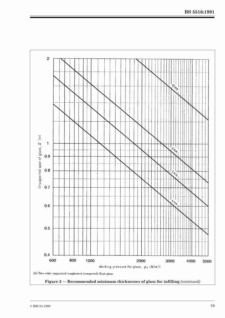
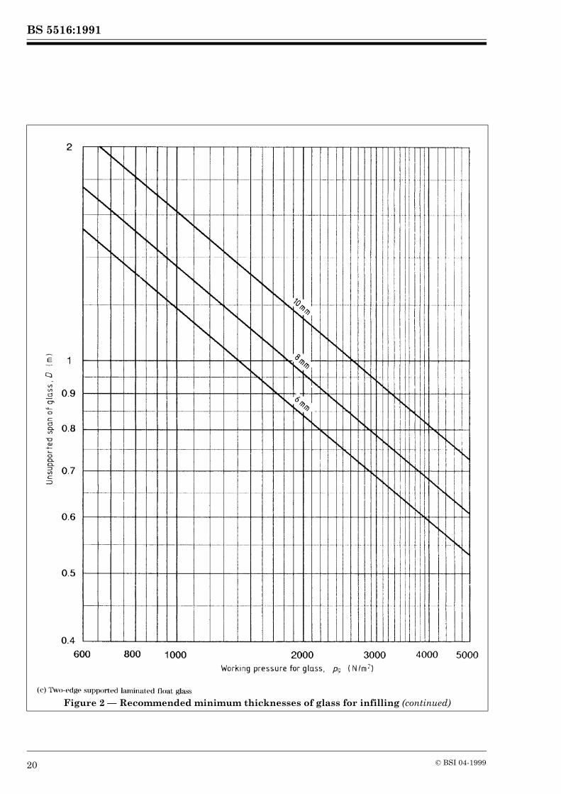
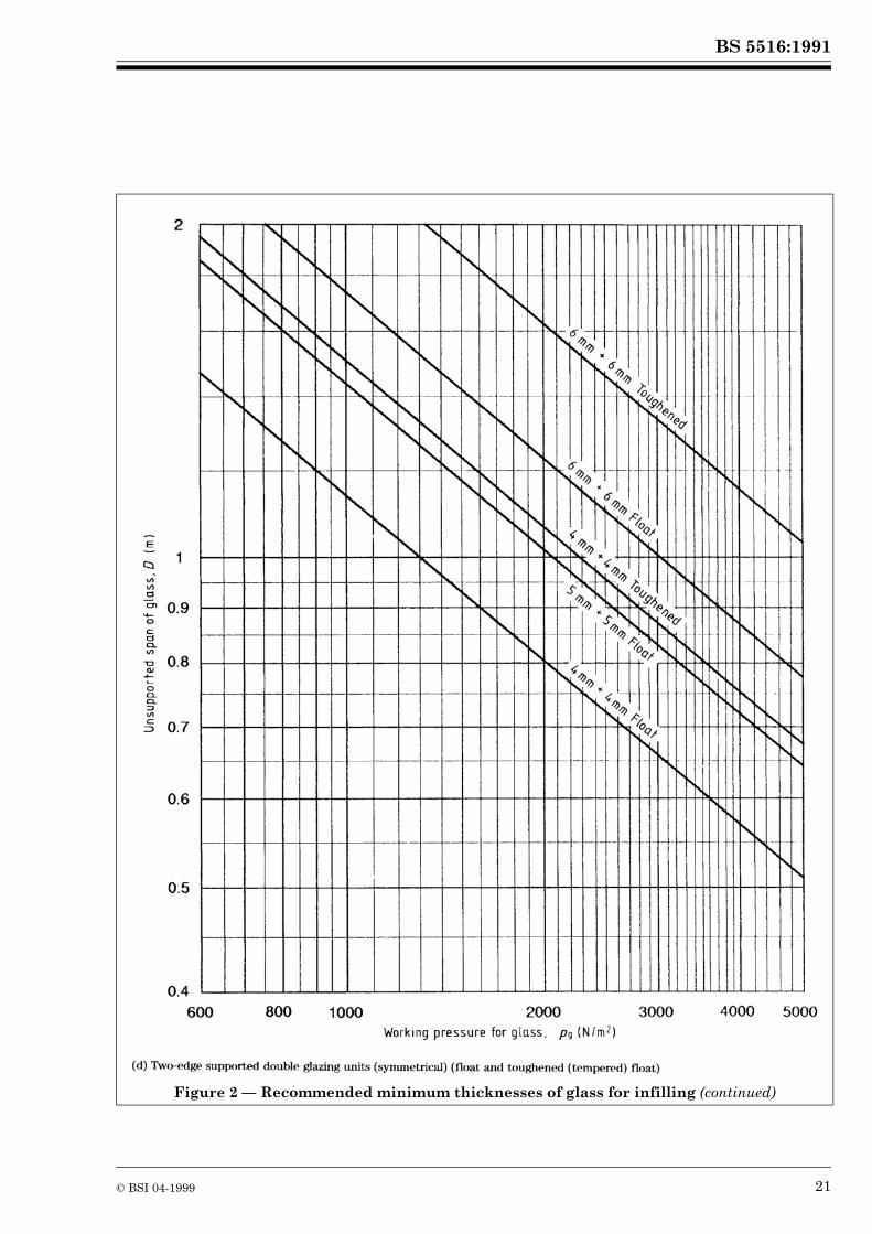
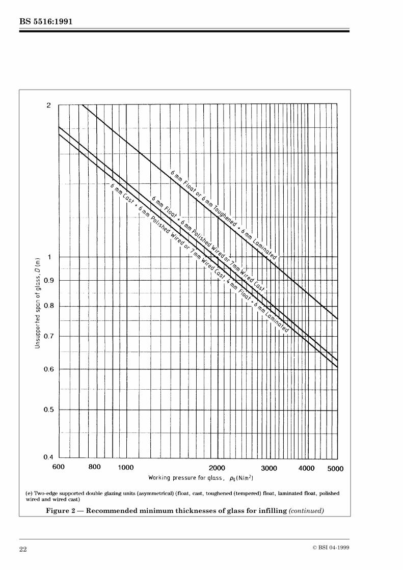
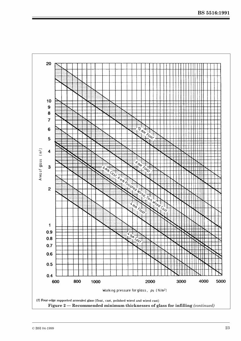
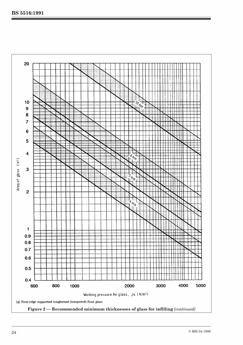
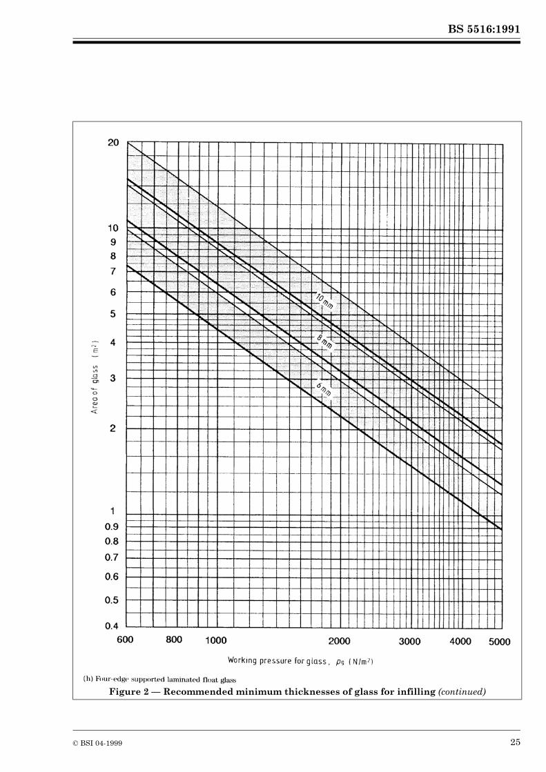
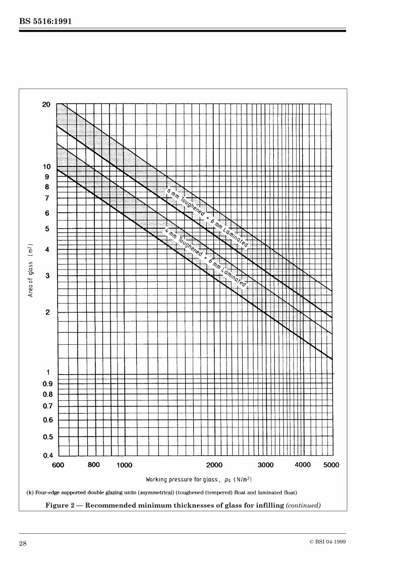
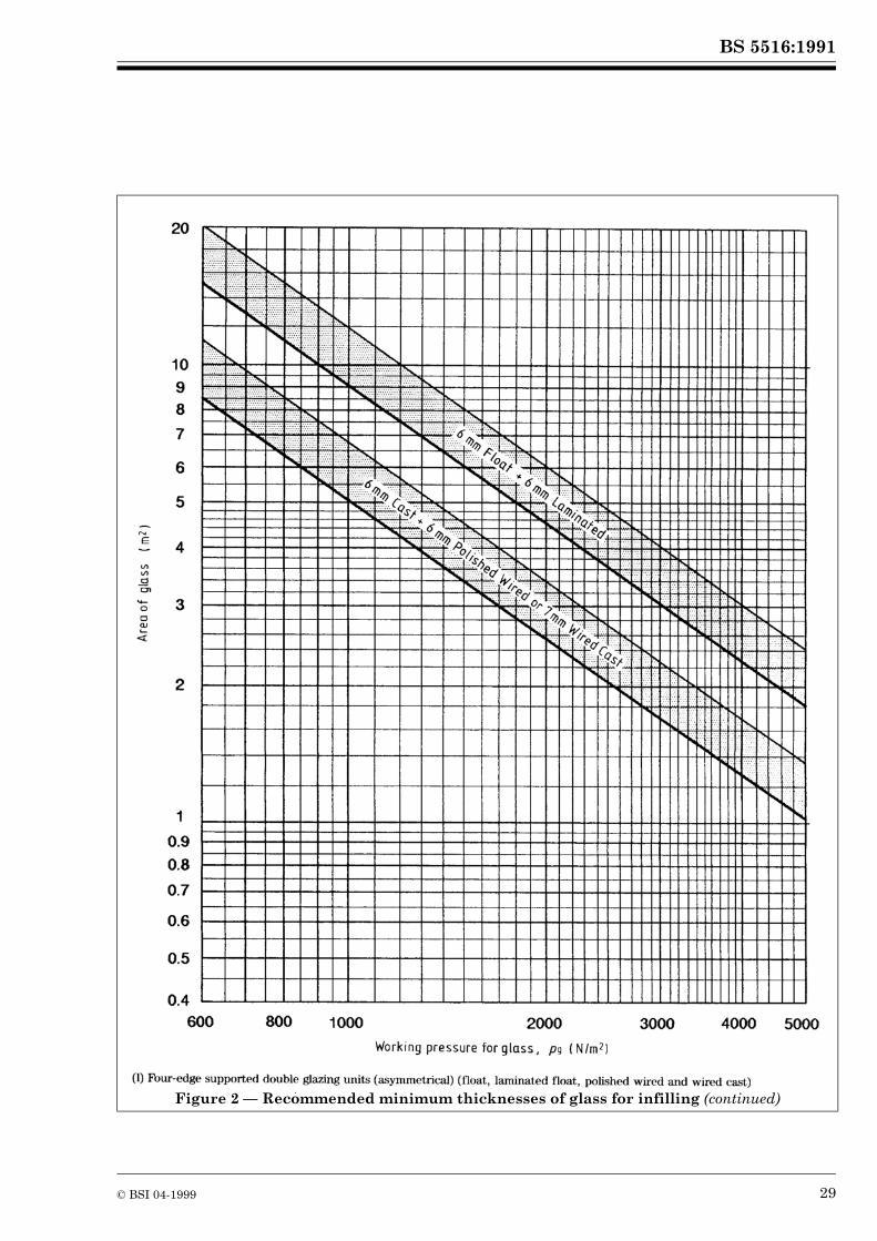
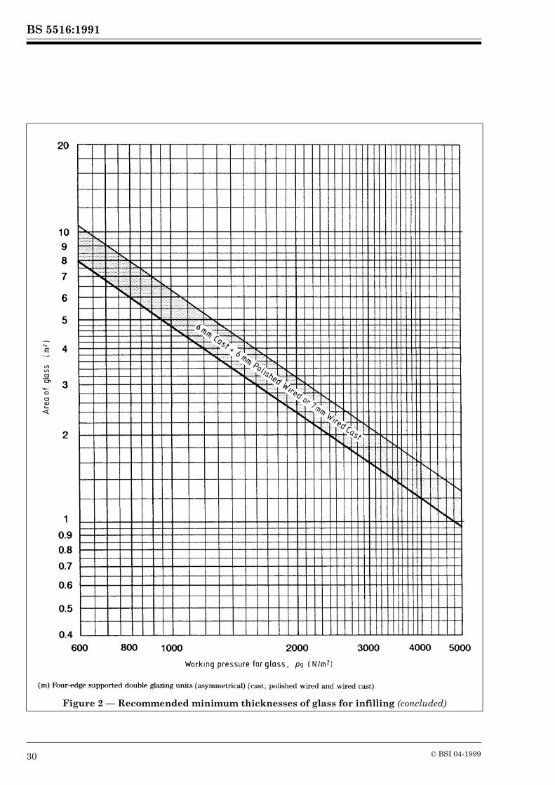
Working pressures for glass determined on the basis of a 3 s gust wind load, taking account of sustained loading effects as described in 10.5.3.1, are used to calculate the minimum thickness or maximum size of pane by a graphic technique. The procedure given below is for rectangular panes of annealed and processed flat glass, as described in BS 952-1, used in a system of patent glazing in which the supporting members provide a minimum edge cover of 7 mm and which do not deflect under maximum design load by more than the appropriate limits given in 10.6.1.3. The procedure applies to glass in single glazing, to each pane of glass in double glazing comprising two separate and mechanically independent layers of glass and to hermetically sealed double glazing units.The graphs may be used to determine the recommended minimum thickness of glass type for a given unsupported span or area of glass, according to the number of edges by which the glass is fully supported.Figure 2(a) to Figure 2(e) are for glass which is fully supported on two opposite, longitudinal edges only and for glass which is fully supported on all four edges having an aspect ratio of pane greater than 3 : 1.Figure 2(f) to Figure 2(m) are for glass which is fully supported on all four edges having an aspect ratio of pane not greater than 3 : 1. These graphs show a shaded band for each glass thickness. The lower edge of the shaded band should be used when the pane of glass is square, i.e. the aspect ratio of pane is 1 : 1; the upper edge of the shaded band represents the additional strength of a pane of glass whose shape is such that the length of the longer side is three times that of the shorter side, i.e. the aspect ratio of pane is 3 : 1; interpolation in direct proportion can be made for intermediate values of the aspect ratio of pane. As noted in 10.6.2.1, if the aspect ratio of pane is greater than 3 : 1 the glass is considered to be fully supported on two opposite long edges only, the length of the shorter side being treated as the unsupported span of glass for use in Figure 2(a) to Figure 2(e). For glass to be considered as fully supported on all four edges, up to an aspect ratio of pane of 3 : 1, the deflection of each supporting member should not exceed the appropriate limits given in 10.6.1.3. For other support conditions and for non-rectangular panes, the glass manufacturer should be consulted.
In the graphs, the minimum tolerances on glass thicknesses given in BS 952-1 have been used together with design stresses based on experience, experimental knowledge and statistical methods of analysis. Compliance of a glass design with working pressure does not imply suitability of use; other recommendations of this standard and other design requirements may also need to be followed. Glass having to withstand only low working pressure, notably in vertical patent glazing in sheltered situations or patent glazing used internally, may need to be increased in thickness or reduced in size in order to avoid excessive deflection under hand pressure, e.g. during cleaning operations. For design purposes, therefore, it is recommended that a minimum working pressure for glass of 800 N/m2 should be allowed.Figure 2(b), Figure 2(d), Figure 2(g) and Figure 2(j) for toughened (tempered) glass are based on the design stress for fully toughened (tempered) glass. This may lead to a glass design which, although mechanically safe, has large and possibly visually disturbing deflections under maximum load and detailed design consideration will be needed.The laminated glasses referred to inFigure 2(c), Figure 2(e), Figure 2(h), Figure 2(j) and Figure 2(k) are symmetrical three-ply laminated glass incorporating an interlayer of polyvinyl butyral. Thicknesses shown are nominal and based on the total glass thicknesses only.Figure 2(d), Figure 2(e) and Figure 2(i) toFigure 2(m) are for hermetically sealed double glazing units in which the supported edges are flush. If any of the supported edges of the unit are not flush then such units should be treated as though they are single glass of the type and thickness of the larger pane.For other glass types and thicknesses, for other constructions of laminated glass and for other glass combinations in hermetically sealed double glazing units, reference should be made to the glass manufacturer for recommendations.
10.8.2 Plastics glazing sheet materials
10.8.2.1 General
Working pressures for plastics glazing sheet materials, determined on the basis of a 3 s gust wind load, taking account of sustained loading effects as described in 10.5.3.2, are used to calculate the minimum thickness or maximum size of pane by a graphic technique in the case of solid plastics glazing sheet materials. In the case of hollow section plastics glazing sheet materials, these working pressures are used to determine the required form of hollow section sheet by reference to the plastics glazing sheet material manufacturer.
BS 5516:1991
16 © BSI 04-1999
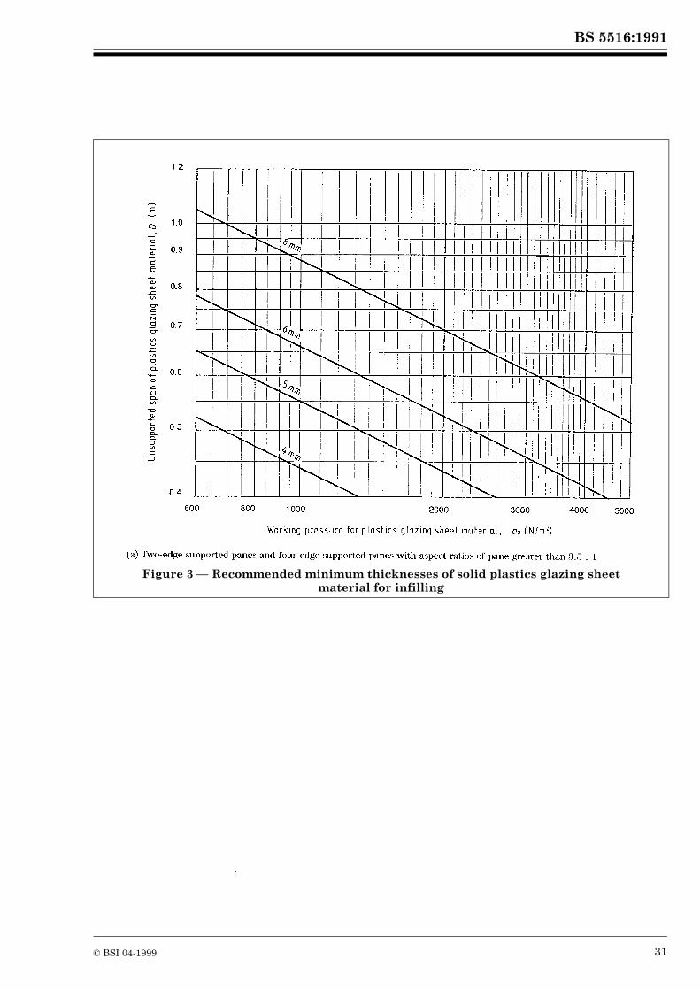
The procedures given below are for rectangular panes of plastics glazing sheet materials as described in 6.3 used in a system of patent glazing in which the supporting members do not deflect under maximum design load by more than the appropriate limits given in 10.6.1.3.These procedures apply to single glazing or each pane in double glazing made up of two separate and mechanically independent layers.Compliance of a plastics glazing sheet material design with working pressures does not imply suitability of use. Other recommendations of this standard as well as other design requirements, such as vandal resistance, may also need to be satisfied.
10.8.2.2 Solid sheets
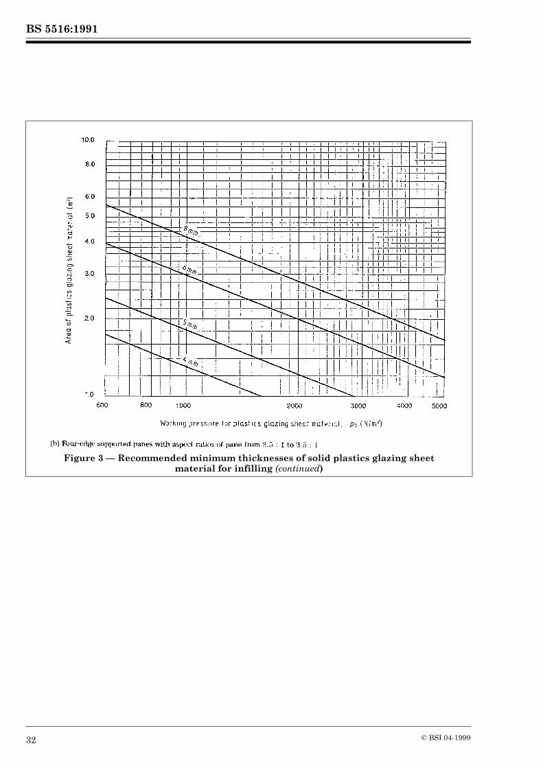
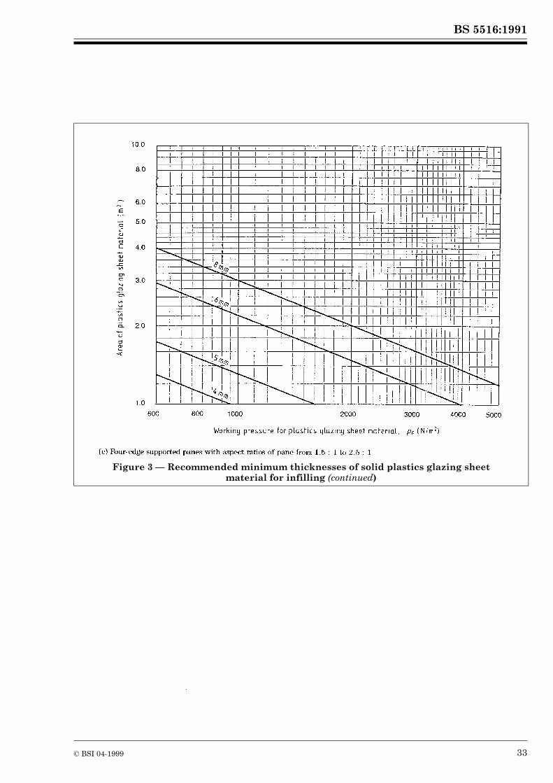
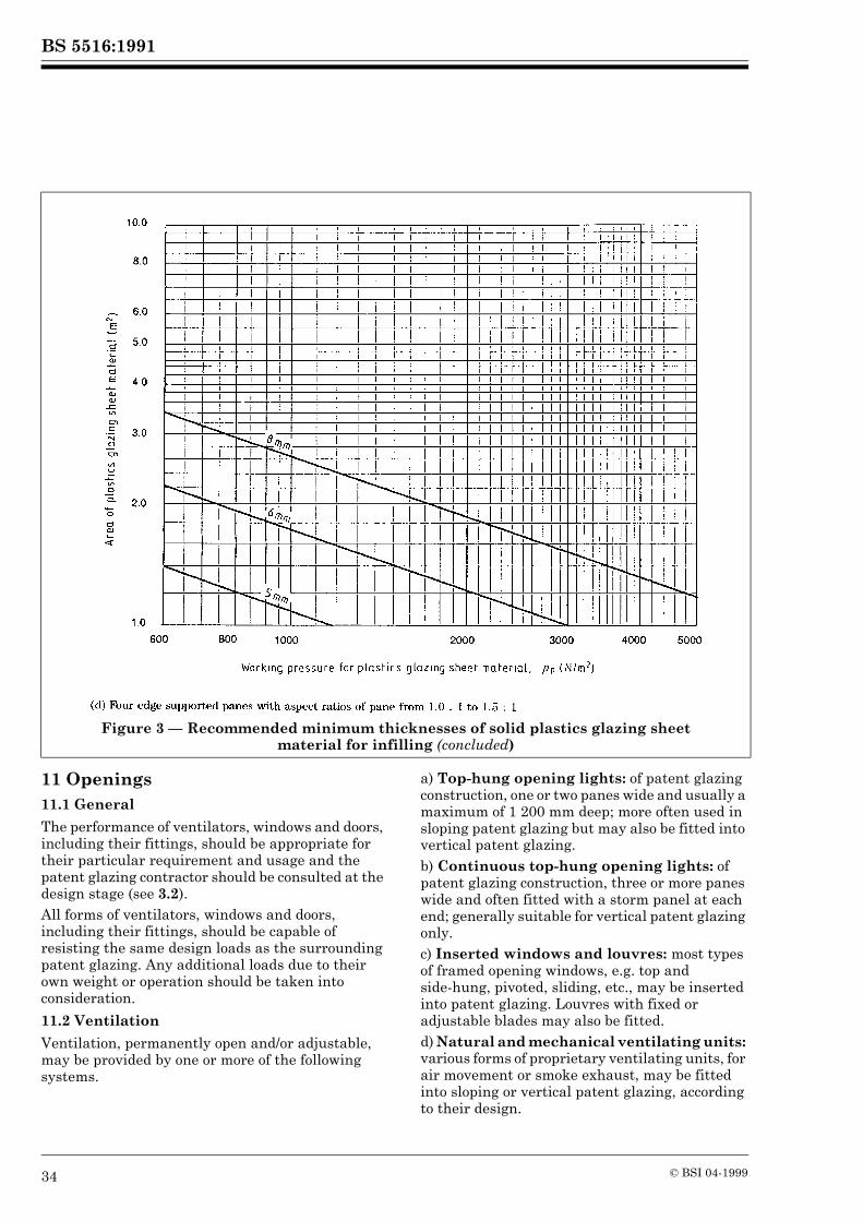
(a) is for solid plastics glazing sheet material which is fully supported along two opposite, longitudinal edges only and for solid plastics glazing sheet material which is fully supported on all four edges having an aspect ratio of pane greater than 3.5 : 1.(b), (c) and (d) are for solid plastics glazing sheet material which is fully supported on all four edges having aspect ratios of pane in the ranges 2.5 : 1 to 3.5 : 1, 1.5 : 1to 2.5 : 1 and 1.0 : 1 to 1.5 : 1 respectively.As noted in 10.6.2.2, if the aspect ratio of pane is greater than 3.5 : 1, the solid plastics glazing sheet material is considered to be fully supported on two opposite long edges only, the length of the shorter side being treated as the unsupported span for use in (a). For solid plastics glazing sheet material to be considered as fully supported on all four edges, up to an aspect ratio of pane of 3.5 : 1, the deflection of each supporting member should not exceed the appropriate limits given in 10.6.1.3. For other support conditions and for non-rectangular panes the manufacturer of the plastics glazing sheet material should be consulted.In the graphs in , the minimum requirements for edge cover of plastics glazing sheet material have been used. (See Appendix J.) If these requirements cannot be fully satisfied, other methods of glazing may be employed and the manufacturer should be consulted.
10.8.2.3 Hollow section sheets
The stiffness of a hollow section plastics glazing sheet material is determined by the material from which it is made, the overall thickness and geometry of the sheet. In addition, in a system of patent glazing in which the infilling is fully supported on all four edges, the deflection characteristics of a particular hollow section plastics glazing sheet material vary according to which direction the webs run in relation to the long edges of the pane. It is not practical, therefore, to produce a set of graphs relating working pressures to hollow section sheets because of the variety of profiles and thicknesses in existence, and the possibility of more to come. In the case of hollow section plastics glazing sheet materials fully supported on all four edges, advice should therefore be obtained from the manufacturer.In a two-edge system of patent glazing, transverse bending of the infilling is a function of the working pressure pp, the unsupported span D and the form of hollow section sheet. For rectangular panes of hollow section plastics glazing sheet materials which are fully supported on two opposite, longitudinal edges only, the calculated value (pp × D2)/8 N·m should not exceed the permissible bending moment for the particular hollow section sheet. The above expression assumes that the pane is simply supported along its edges and does not take account of any clamping effect which may be produced by the supporting members at the edges of the pane. This clamping effect, which varies according to the form of hollow section, increases the resistance of the pane to flexing and becomes more significant as the unsupported span decreases. Whilst it is not practical to give precise details for all possible cases, where the unsupported span is approximately 0.7 m or less advice may be obtained from the manufacturer.For external patent glazing, rectangular panes of hollow section plastics glazing sheet materials are normally installed with the webs parallel to the longitudinal supporting members, i.e. in the direction of the slope or the flow of water for sloping patent glazing and vertically for vertical patent glazing. Therefore for hollow section plastics glazing sheet materials which are fully supported on two opposite, longitudinal edges only, the manufacturer should provide a value for the permissible bending moment for the particular hollow section sheet, supported parallel to the webs. In the case of hollow section plastics glazing sheet material with a non-symmetrical profile, i.e. with different permissible bending moments according to the direction in which the load is applied, only the lower value should be used.
BS 5516:1991
© BSI 04-1999 17
In all cases, the minimum requirements for edge cover should be satisfied (see Appendix J). Information supplied by the manufacturer should also satisfy these requirements. If these requirements cannot be fully satisfied, other methods of glazing may be employed and the manufacturer should be consulted.
10.8.3 Other infill materials
For other infill materials the minimum thickness/maximum size should be in accordance with the manufacturer’s recommendations.

BS 5516:1991
18 © BSI 04-1999
Figure 2 — Recommended minimum thicknesses of glass for infilling
BS 5516:1991
© BSI 04-1999 19
Figure 2 — Recommended minimum thicknesses of glass for infilling (continued)
BS 5516:1991
20 © BSI 04-1999
Figure 2 — Recommended minimum thicknesses of glass for infilling (continued)
BS 5516:1991
© BSI 04-1999 21
Figure 2 — Recommended minimum thicknesses of glass for infilling (continued)
BS 5516:1991
22 © BSI 04-1999
Figure 2 — Recommended minimum thicknesses of glass for infilling (continued)
BS 5516:1991
© BSI 04-1999 23
Figure 2 — Recommended minimum thicknesses of glass for infilling (continued)
BS 5516:1991
24 © BSI 04-1999
Figure 2 — Recommended minimum thicknesses of glass for infilling (continued)
BS 5516:1991
© BSI 04-1999 25
Figure 2 — Recommended minimum thicknesses of glass for infilling (continued)

BS 5516:1991
26 © BSI 04-1999
Figure 2 — Recommended minimum thicknesses of glass for infilling (continued)

BS 5516:1991
© BSI 04-1999 27
Figure 2 — Recommended minimum thicknesses of glass for infilling (continued)
BS 5516:1991
28 © BSI 04-1999
Figure 2 — Recommended minimum thicknesses of glass for infilling (continued)
BS 5516:1991
© BSI 04-1999 29
Figure 2 — Recommended minimum thicknesses of glass for infilling (continued)
BS 5516:1991
30 © BSI 04-1999
Figure 2 — Recommended minimum thicknesses of glass for infilling (concluded)
BS 5516:1991
© BSI 04-1999 31
Figure 3 — Recommended minimum thicknesses of solid plastics glazing sheet material for infilling
BS 5516:1991
32 © BSI 04-1999
Figure 3 — Recommended minimum thicknesses of solid plastics glazing sheet material for infilling (continued)
BS 5516:1991
© BSI 04-1999 33
Figure 3 — Recommended minimum thicknesses of solid plastics glazing sheet material for infilling (continued)
BS 5516:1991
34 © BSI 04-1999
11 Openings11.1 General
The performance of ventilators, windows and doors, including their fittings, should be appropriate for their particular requirement and usage and the patent glazing contractor should be consulted at the design stage (see 3.2).All forms of ventilators, windows and doors, including their fittings, should be capable of resisting the same design loads as the surrounding patent glazing. Any additional loads due to their own weight or operation should be taken into consideration.
11.2 Ventilation
Ventilation, permanently open and/or adjustable, may be provided by one or more of the following systems.
a) Top-hung opening lights: of patent glazing construction, one or two panes wide and usually a maximum of 1 200 mm deep; more often used in sloping patent glazing but may also be fitted into vertical patent glazing.b) Continuous top-hung opening lights: of patent glazing construction, three or more panes wide and often fitted with a storm panel at each end; generally suitable for vertical patent glazing only.c) Inserted windows and louvres: most types of framed opening windows, e.g. top and side-hung, pivoted, sliding, etc., may be inserted into patent glazing. Louvres with fixed or adjustable blades may also be fitted.d) Natural and mechanical ventilating units: various forms of proprietary ventilating units, for air movement or smoke exhaust, may be fitted into sloping or vertical patent glazing, according to their design.
Figure 3 — Recommended minimum thicknesses of solid plastics glazing sheet material for infilling (concluded)

BS 5516:1991
© BSI 04-1999 35
Power fans for inlet or extraction, made of metals, plastics or other materials, may be incorporated into patent glazing, either vertical or sloping, according to the design of the component. In sloping patent glazing, however, such fans should never be mounted directly in a pane of glass.When considering the installation of heavy duty power fans or other ventilators with high dead loads, it may be necessary to support these independently on suitable trimmer frames which are fixed directly to the main structural members. In such cases, the patent glazing contractor should be consulted at the initial design stage (see 3.2).
11.3 Entrances
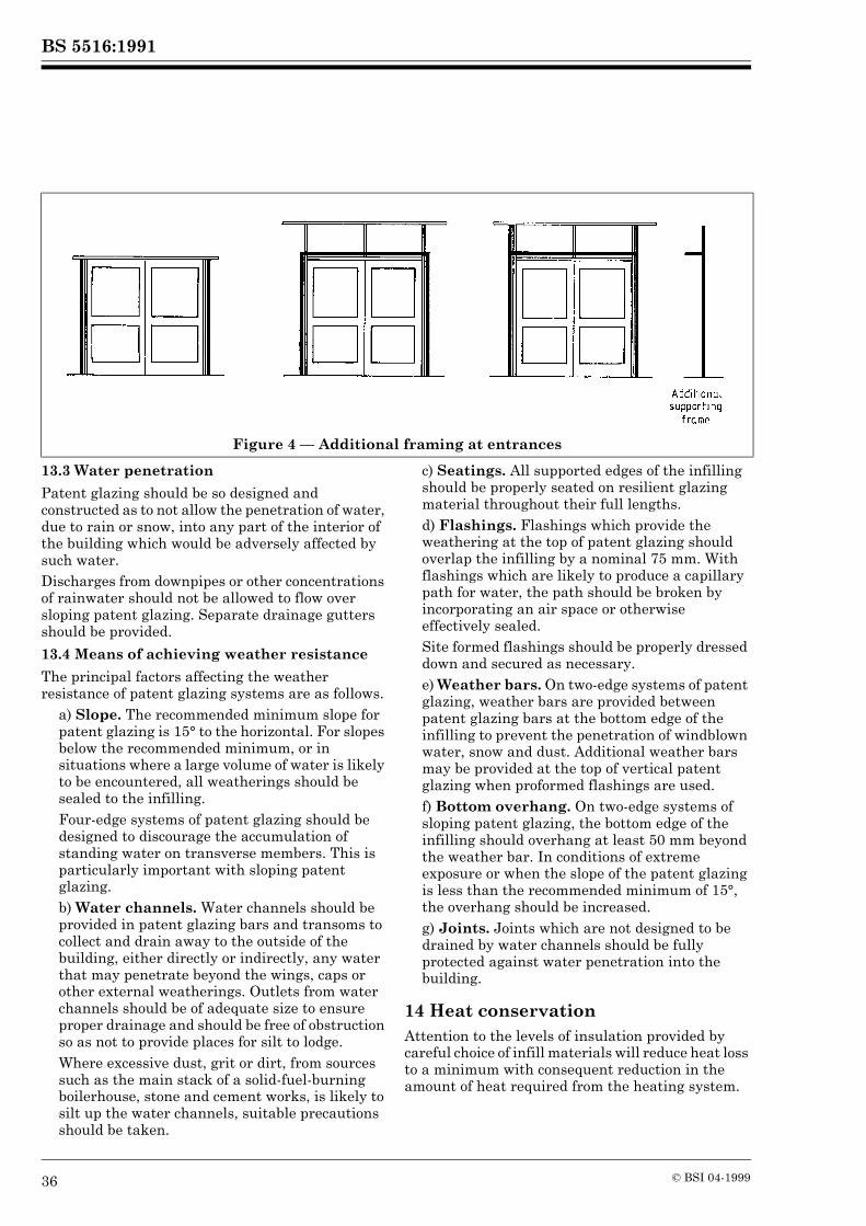
Doors of various types, including hinged, pivoted or sliding, with their frames, may be incorporated within an area of patent glazing either as integral doors or as separate door composites. Where patent glazing incorporates an entrance, including one not extending to the full height of the patent glazing, it may be necessary to provide an additional supporting frame for the patent glazing around the entrance. This should be fixed to the main structure to ensure that vibration or other loads are not transmitted to the patent glazing. (See .)
12 Fire12.1 General
Patent glazing, when used in roofs and walls of buildings, may need to incorporate infill materials which have specific external and/or internal fire performance properties.The performance requirements are dictated by various parameters including purpose group, location, situation, size and special design requirements.
12.2 Fire resistance
Where elements of structure require a level of fire resistance when tested in accordance with BS 476-20 and BS 476-22, only certain types of patent glazing systems will be suitable; these may be either tested or agreed as “deemed to satisfy” by local fire authorities or local authority building inspectors.
12.3 Other fire performance properties
12.3.1 Glass infilling
Most types of glass classified in BS 952 have the fire performance properties given in Table 1. For specific information refer to PD 6512-3.
Table 1 — Fire performance of glass
12.3.2 Plastics glazing sheet material infilling
The fire performance characteristics of thermoplastics glazing sheet material are dependent upon the type and grade of polymer, the form of the sheet product, its colour and its thickness. Therefore the fire performance characteristics of a specific plastics glazing sheet material should be obtained from its manufacturer.
12.3.3 Other materials and components
Manufacturers should be consulted for information on the appropriate fire performance properties of their materials.
13 Weather resistance13.1 General
The degree of exposure and the particular situation of the patent glazing should be taken into account when considering weather resistance and the type of system to be employed.Consideration should also be given to the intended use and occupancy of the building, together with any specific performance criteria. The patent glazing contractor should be provided with the necessary information at the initial design stage (see 3.2).
13.2 Air permeability
Resistance of patent glazing to air permeation will depend upon several factors including the type of system employed.In view of the large variety of designs available it is not practical to give quantified information. Generally four-edge systems provide a higher level of resistance than two-edge systems. If a specific level of performance is required in respect of air permeability, this should be specified by the building designer and agreed with the patent glazing contractor at initial design stage (see 3.2).
Characteristic Test method
Rating
External fire exposure
BS 476-3 AA
Non-combustibility BS 476-4 Non-combustible
Fire propagation index
BS 476-6 I # 12i1 # 6
Surface spread of flame
BS 476-7 Class 1
BS 5516:1991
36 © BSI 04-1999
13.3 Water penetration
Patent glazing should be so designed and constructed as to not allow the penetration of water, due to rain or snow, into any part of the interior of the building which would be adversely affected by such water.Discharges from downpipes or other concentrations of rainwater should not be allowed to flow over sloping patent glazing. Separate drainage gutters should be provided.
13.4 Means of achieving weather resistance
The principal factors affecting the weather resistance of patent glazing systems are as follows.
a) Slope. The recommended minimum slope for patent glazing is 15° to the horizontal. For slopes below the recommended minimum, or in situations where a large volume of water is likely to be encountered, all weatherings should be sealed to the infilling.Four-edge systems of patent glazing should be designed to discourage the accumulation of standing water on transverse members. This is particularly important with sloping patent glazing.b) Water channels. Water channels should be provided in patent glazing bars and transoms to collect and drain away to the outside of the building, either directly or indirectly, any water that may penetrate beyond the wings, caps or other external weatherings. Outlets from water channels should be of adequate size to ensure proper drainage and should be free of obstruction so as not to provide places for silt to lodge.Where excessive dust, grit or dirt, from sources such as the main stack of a solid-fuel-burning boilerhouse, stone and cement works, is likely to silt up the water channels, suitable precautions should be taken.
c) Seatings. All supported edges of the infilling should be properly seated on resilient glazing material throughout their full lengths.d) Flashings. Flashings which provide the weathering at the top of patent glazing should overlap the infilling by a nominal 75 mm. With flashings which are likely to produce a capillary path for water, the path should be broken by incorporating an air space or otherwise effectively sealed.Site formed flashings should be properly dressed down and secured as necessary.e) Weather bars. On two-edge systems of patent glazing, weather bars are provided between patent glazing bars at the bottom edge of the infilling to prevent the penetration of windblown water, snow and dust. Additional weather bars may be provided at the top of vertical patent glazing when proformed flashings are used.f) Bottom overhang. On two-edge systems of sloping patent glazing, the bottom edge of the infilling should overhang at least 50 mm beyond the weather bar. In conditions of extreme exposure or when the slope of the patent glazing is less than the recommended minimum of 15°, the overhang should be increased.g) Joints. Joints which are not designed to be drained by water channels should be fully protected against water penetration into the building.
14 Heat conservationAttention to the levels of insulation provided by careful choice of infill materials will reduce heat loss to a minimum with consequent reduction in the amount of heat required from the heating system.
Figure 4 — Additional framing at entrances
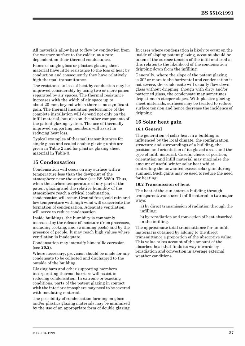
BS 5516:1991
© BSI 04-1999 37
All materials allow heat to flow by conduction from the warmer surface to the colder, at a rate dependent on their thermal conductance.Panes of single glass or plastics glazing sheet material have little resistance to the loss of heat by conduction and consequently they have relatively high thermal transmittance.The resistance to loss of heat by conduction may be improved considerably by using two or more panes separated by air spaces. The thermal resistance increases with the width of air space up to about 20 mm, beyond which there is no significant gain. The thermal insulation performance of the complete installation will depend not only on the infill material, but also on the other components of the patent glazing system. The use of thermally improved supporting members will assist in reducing heat loss.Typical examples of thermal transmittances for single glass and sealed double glazing units are given in Table 2 and for plastics glazing sheet material in Table 3.
15 CondensationCondensation will occur on any surface with a temperature less than the dewpoint of the atmosphere near the surface (see BS 5250). Thus, when the surface temperature of any part of the patent glazing and the relative humidity of the atmosphere reach a critical combination, condensation will occur. Ground frost, cold rain and low temperature with high wind will exacerbate the formation of condensation. Adequate ventilation will serve to reduce condensation.Inside buildings, the humidity is commonly increased by the release of moisture (from processes, including cooking, and swimming pools) and by the presence of people. It may reach high values where ventilation is inadequate.Condensation may intensify bimetallic corrosion (see 20.2).Where necessary, provision should be made for any condensate to be collected and discharged to the outside of the building.Glazing bars and other supporting members incorporating thermal barriers will assist in reducing condensation. In extreme or exacting conditions, parts of the patent glazing in contact with the interior atmosphere may need to be covered with insulating material.The possibility of condensation forming on glass and/or plastics glazing materials may be minimized by the use of an appropriate form of double glazing.
In cases where condensation is likely to occur on the inside of sloping patent glazing, account should be taken of the surface tension of the infill material as this relates to the likelihood of the condensation dripping down from the infilling.Generally, where the slope of the patent glazing is 30° or more to the horizontal and condensation is not severe, the condensate will usually flow down glass without dripping; though with dirty and/or patterned glass, the condensate may sometimes drip at much steeper slopes. With plastics glazing sheet materials, surfaces may be treated to reduce surface tension and hence decrease the incidence of dripping.
16 Solar heat gain16.1 General
The generation of solar heat in a building is influenced by the local climate, the configuration, structure and surroundings of a building, the position and orientation of its glazed areas and the type of infill material. Careful choice of position, orientation and infill material may maximize the amount of useful winter solar heat whilst controlling the unwanted excess solar gain during summer. Such gains may be used to reduce the need for heating.
16.2 Transmission of heat
The heat of the sun enters a building through transparent/translucent infill material in two major ways:
a) by direct transmission of radiation through the infilling;b) by reradiation and convection of heat absorbed in the infilling.
The approximate total transmittance for an infill material is obtained by adding to the direct transmittance a proportion of the absorptive value. This value takes account of the amount of the absorbed heat that finds its way inwards by reradiation and convection in average external weather conditions.
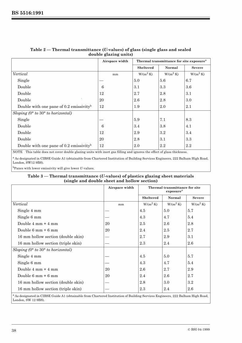
BS 5516:1991
38 © BSI 04-1999
Table 2 — Thermal transmittance (U-values) of glass (single glass and sealed double glazing units)
Table 3 — Thermal transmittance (U-values) of plastics glazing sheet materials (single and double sheet and hollow section)
Airspace width Thermal transmittance for site exposurea
Sheltered Normal Severe
Vertical mm W/(m2·K) W/(m2·K) W/(m2·K)
Single — 5.0 5.6 6.7
Double 6 3.1 3.3 3.6
Double 12 2.7 2.8 3.1
Double 20 2.6 2.8 3.0
Double with one pane of 0.2 emissivityb 12 1.9 2.0 2.1
Sloping (0° to 30° to horizontal)
Single — 5.9 7.1 8.3
Double 6 3.4 3.8 4.1
Double 12 2.9 3.2 3.4
Double 20 2.8 3.1 3.3
Double with one pane of 0.2 emissivityb 12 2.0 2.2 2.2NOTE This table does not cover double glazing units with inert gas filling and ignores the effect of glass thickness.
a As designated in CIBSE Guide A1 (obtainable from Chartered Institution of Building Services Engineers, 222 Balham High Road, London, SW12 9BS).bPanes with lower emissivity will give lower U-values.
Airspace width Thermal transmittance for site exposurea
Sheltered Normal Severe
Vertical mm W/(m2·K) W/(m2·K) W/(m2·K)
Single 4 mm — 4.5 5.0 5.7
Single 6 mm — 4.3 4.7 5.4
Double 4 mm + 4 mm 20 2.5 2.6 2.8
Double 6 mm + 6 mm 20 2.4 2.5 2.7
16 mm hollow section (double skin) — 2.7 2.9 3.1
16 mm hollow section (triple skin) — 2.3 2.4 2.6
Sloping (0° to 30° to horizontal)
Single 4 mm — 4.5 5.0 5.7
Single 6 mm — 4.3 4.7 5.4
Double 4 mm + 4 mm 20 2.6 2.7 2.9
Double 6 mm + 6 mm 20 2.4 2.6 2.7
16 mm hollow section (double skin) — 2.8 3.0 3.2
16 mm hollow section (triple skin) — 2.3 2.4 2.6a As designated in CIBSE Guide A1 (obtainable from Chartered Institution of Building Services Engineers, 222 Balham High Road, London, SW 12 9BS).
BS 5516:1991
© BSI 04-1999 39
The solar performance characteristics of infill materials are identified by one or other of the following concepts, depending on the method of calculation being used for determination of the solar heat gain.
1) Shading coefficient1) The shading coefficient is the total solar transmittance of the infill material divided by 0.87.NOTE 0.87 is the total solar transmittance of a notional 3 mm to 4 mm thick clear glass.
2) Solar gain factor2)
i) Solar gain factor is the quotient of the daily mean solar cooling load due to the infill material and the daily mean solar irradiance received on the glazing.ii) Alternating solar gain factor is the quotient of the instantaneous cyclic cooling load due to the infill material and the instantaneous cyclic solar irradiance received on the glazing.
The appropriate manufacturer should be consulted on values of shading coefficient or solar gain factor for a specific glass or plastics glazing sheet material.
16.3 Control of solar heat gain
16.3.1 Glass
The heating effects of solar radiation may be reduced by the use of solar control glass. There is considerable variation in the values of absorptance and reflectance between different types of solar control glass and these may also be used in combinations in double glazing. Manufacturers should be consulted for details.
16.3.2 Plastics glazing sheet materials
Types of plastics glazing sheet materials that reduce the transmission of solar radiation are available. Manufacturers should be consulted for details.
16.3.3 Reflective treatments
The application of whitewash, dilute white emulsion paint or specially formulated white obscurants to the infilling may reduce the amount of solar heat transmitted. Obscurants, whether required to be temporary or permanent, should be carefully selected as they may make the infill material heat-absorbing and, in the case of plastics glazing sheet materials, it is essential that they should be chemically compatible. The infill material manufacturer should be consulted for advice.
When applying obscurants, care should be taken to prevent excess material being brushed or swilled under flashings and weatherings, as this may cause subsequent leakage. Alkaline obscurants, e.g. cement washes, should not be used, as they may damage the surface of the infilling and may attack aluminium.
16.3.4 Solar control plastics films
These are normally coloured and/or reflective and may be applied to infill materials to produce reflecting/absorbing surfaces. The performance of the infill material/film combination will depend on the nature of the film and the surfaces to which it is attached.The use of plastics films on infill materials may increase the heat-absorbing properties of the infill materials. Consideration should also be given to chemical compatibility between plastics films and plastics glazing sheet materials.In the case of hollow plastics glazing sheet materials, plastics films should not be applied to the interior surface.
16.3.5 Shading devices
Shading devices should be used in situations where direct or reflected glare, thermal discomfort or direct sunshine is likely to be a problem.
a) Internal shading devices, either between two panes or on the room side of the infilling, are less efficient than external devices, and allow different solar heat gains, dependent on their properties and their position in relation to the infilling.b) External shading devices give more efficient reduction of solar heat gain than internal shading devices. They will reduce instantaneous heat gain by ensuring that heat is dissipated externally. When external shading devices are to be used, they should be considered as an element in the appearance of the building.
1) Based on a definition taken from American Society of Heating Refrigerating and Air Conditioning Engineers (ASHRAE) Handbook Fundamentals, 1989. Available from ASHRAE Publication Sales, 1791, Tullie Circle, NE Atlanta, GA 30329.2) Based on definitions taken from Chartered Institution of Building Services Engineers (CIBSE) Guide Section A5, Thermal Response of Buildings, 1979. Available from CIBSE, 222 Balham High Road, London SW 12 9BS.
BS 5516:1991
40 © BSI 04-1999
17 Thermal safety17.1 Glass
When glass is directly exposed to solar radiation it will absorb heat which will lead to an increase in its temperature and hence expansion. Some or all of the edges of the glass are shielded from the radiation and hence remain cool, and the resulting differential expansion produces tensile stresses in and parallel to the edge of the glass. The likelihood of thermal fracture depends on the magnitude of the stress induced.Thermal stress in glass and consideration of its assessment is described in Appendix K. Thermal safety related to particular circumstances is not considered, such detail being the subject of glass manufacturers’ literature or of their specialist knowledge.
17.2 Plastics glazing sheet materials
In general, when plastics glazing sheet materials are used for infilling thermal safety need not be considered. However, plastics glazing sheet material is subject to thermal stress when the temperature of all or part of the pane exceeds its maximum continuous service temperature. The two principal situations in which this may occur are as follows.
a) When a dark tinted plastics glazing sheet material, having a low maximum continuous service temperature, is exposed to high levels of direct solar radiation, such as in south facing sloping glazing: in such a case, the solar energy absorbed by the pane may raise its temperature to a point where mechanical distortion of the pane occurs.b) When a transparent plastics glazing sheet material possessing a high solar energy transmission value is exposed to high levels of direct solar radiation in a system of patent glazing which includes dark coloured component parts close to or in contact with the plastics glazing sheet material, particularly the inner surface: such components will absorb the transmitted solar energy, converting it into heat energy, which will be radiated back to the inner surface of the sheet and may lead to localized stress cracking.Localized stress cracking resulting from thermal stress may be minimized by ensuring that components in positions likely to absorb solar energy transmitted through the plastics glazing sheet material are light coloured on the side facing the sheet.
Contact with chemically incompatible substances (e.g. unsuitable sealing and glazing materials) may also add to any problems resulting from thermal stress (see J.5).Plastics glazing sheet materials have high coefficients of thermal expansion and the appropriate allowances for sizing should be made (see J.2). Mechanical distortion of a pane may result from thermal movement if the pane is incorrectly glazed.NOTE Polycarbonate has a high maximum continuous service temperature and is much less at risk from thermal problems than other plastics glazing sheet materials. Advice should be sought from manufacturers.
18 Transmission of light18.1 General
The transmission of light into buildings by transparent/translucent infill materials is affected by a number of variables. However, it is sufficient for most purposes to consider a simplified and approximate transmittance representing the proportion of visible light from a diffuse source such as an overcast sky, which emerges from the interior face of the infill material.In view of the number of possible glass and plastics glazing sheet materials that are available, it is not practical to give light transmission values. The glass or plastics glazing sheet materials manufacturer should be consulted.Detailed information on natural lighting, glare, privacy and accumulation of dirt is given in the CIBSE Applications Manual AM2 Window Design3)
18.2 Natural lighting
The choice and position of infill materials may maximize the amount of daylight entering a building. If the daylight and artificial light are properly integrated, economies in operation may be achieved. For design guidance concerning assessment and provision of natural lighting, reference should be made to DD 67 for sunlight and DD 73 for daylight.
18.3 Glare
Four manifestations of glare from glass and plastics glazing sheet material should be considered:
a) direct glare from the sun;b) glare from the sky, excluding direct sunlight;c) glare resulting from diffracting or diffusing glass and/or plastics glazing sheet materials of high surface luminance;d) glare resulting from reflection of sunlight and/or skylight.
3) Obtainable from Chartered Institution of Building Services Engineers, 222 Balham High Road, London SW12 9BS.
BS 5516:1991
© BSI 04-1999 41
The control of glare may be achieved by the correct specification of the infill material, its positioning within the building structure and its orientation to control the amount of sunlight transmitted through the glazed area.In addition, because contrast between glazed areas and surrounding opaque areas should also be minimized for glare to be reduced to acceptable levels, it is of greater benefit to maintain the area of glass and/or plastics glazing sheet material and reduce light transmissions than to maintain high light transmittance and reduce the glazed area. Also, to reduce contrast, light coloured interiors should be provided.
18.4 Privacy
The range of different internal and external lighting conditions which are likely to occur should be taken into account when considering the degree of privacy required.An adequate degree of privacy may be provided by a variety of glass or plastics glazing sheet materials and attention to the levels of illuminance.
18.5 Accumulation of dirt on the infilling
An accumulation of dirt will considerably reduce the light transmittance of the infill material but the change may remain unnoticed by the occupants of the building. (See 28.2.)
18.6 Fading of objects
When sunlight or skylight is incident on the interior of a building, fading of objects may occur depending on the nature of the object, duration and intensity of exposure and wavelength of radiation. Fading may be minimized by the orientation of the glazing, i.e. northlight glazing, and/or selection of glass and plastics glazing sheet materials that significantly reduce or do not transmit the wavelengths of radiation which are likely to cause fading.
18.7 Effect of weathering
The light transmission figures quoted by the glass/plastics glazing sheet manufacturers are for new unweathered material. Some types and processed forms of plastics glazing sheet materials have enhanced resistance to weathering. However, some plastics glazing sheet materials may suffer from some reduction of light transmittance due to weathering. Manufacturers should be consulted about the behaviour of their materials.
19 Sound reductionMaterials reduce noise by acting as a barrier to the transmission of sound (insulation) and by damping sound reflection from surfaces (absorption). Consideration should be given to the frequency spectrum of the sound to be reduced.
Sound insulation generally increases with the physical mass of the material. In sealed double glazing units, the insulation effect is only marginally improved by increasing the interpane space. Interlayers in laminated glass may improve the damping effect. While solid and hollow section plastics glazing sheet materials have a lower mass than glass, and therefore a lower insulation value, they have a greater damping effect.For sound reduction values of infill material, the appropriate manufacturer should be consulted.Sound insulation is impaired by openings and gaps which provide alternative pathways for airborne sound transmission. Sound insulation may be improved by the use of continuous, resilient gaskets and sealing materials.
20 Durability20.1 General
The durability of a patent glazing system depends upon the conditions of exposure, the materials and finishes used in the component parts, and the frequency and thoroughness of cleaning and maintenance. Relevant information can be obtained from CP 3:Chapter IX and CP 153-2. The patent glazing contractor should be notified at the initial design stage of any aggressive factor, either inside or outside the building (see 3.2). A classification of atmospheric pollution is given in Appendix VI of CP 3:Chapter IX:1950.All components should withstand the expected natural exposure conditions, atmospheric pollution or other aggressive conditions without failure.
20.2 Patent glazing bars, other supporting members, components and finishes
In urban exposure conditions and mild industrial atmospheres, all the materials described in clause 6 for the components of patent glazing systems may be used. More severe conditions, either internally or externally, may place a restriction on the use of certain materials.Aluminium should not be used where alkaline pollution is expected. Protection should be provided against alkaline solutions formed when rainwater passes over “green” concrete or newly cement-rendered surfaces, and onto aluminium. Acidic atmospheres formed in heavily industrialized environments and/or severe marine conditions may be too aggressive for untreated aluminium to withstand for a long time.The drainage of water from copper or copper alloys onto aluminium or zinc based alloys causes corrosion and should be prevented. Similarly the presence of copper in paints and in abrasive cleaning agents should be avoided.
BS 5516:1991
42 © BSI 04-1999
No two metals able to set up marked bimetallic corrosion should be used in proximity to one another. In locations where condensation may occur bimetallic corrosion may be intensified. Relevant information about bimetallic corrosion is given in PD 6484. Protection may be achieved by anodizing, stove painting or other suitable measures (see 5.5).Care should be taken with the use of lead in the presence of some chemicals, e.g. acetic acid.The effects of excessive heat and/or ultraviolet exposure should be considered. This is particularly relevant where plastics are used.
20.3 lnfillings
20.3.1 Glass
Glass with a composition as classified in BS 952 is generally suitable for use in most exposure conditions. Care should be taken to avoid alkaline solutions running onto the glass surface. Special consideration may need to be given to the use of wired glass and certain types of coated glass in marine or severe industrial atmospheres.The sealant used in the manufacture of double glazing units should be compatible with the expected environmental conditions and, if exposed to high levels of ultraviolet radiation, the sealant should be resistant to such exposure.
20.3.2 Plastics glazing sheet materials
Several plastics glazing sheet materials are known to perform satisfactorily in service but it has not been possible to derive a test that accurately predicts their durability. Information is available from manufacturers.The choice of a particular plastics glazing sheet material may be dictated by the environmental conditions specified. Account should be taken of possible corrosion and of contamination by any extracted chemicals that may be rain-washed over the infilling.
20.3.3 Other infillings
For other types of infilling, the manufacturer’s recommendations should be obtained, relevant to the anticipated weathering and environmental conditions.
20.4 Sealing and glazing materials
Due to the large variety of materials available no specific advice may be offered and the manufacturer of the product should be consulted about its durability.
21 Human safety21.1 General
The risk of human injury arising from fracture and/or penetration of the infilling by impact should be considered. Hazard categories may be limited to areas of patent glazing from which people may be at risk in the course of the normal use of the building. Areas which are used only for the purpose of maintenance need not be considered. When assessing the risk of human injury, a reasonable standard of human behaviour should be assumed for appropriate age groups.Consideration should be given to the type of infill materials for use in the following six areas of hazard which may be associated with patent glazing:
a) overhead sloping glazing, where there is normal access to areas below the infilling;b) doors, door side panels and low level glazing, where the infilling may be subject to accidental human impact;c) bathing areas, where the infilling is adjacent to or surrounding private or public swimming pools;d) special risk areas, where the planned activity generates a special risk;e) inwardly sloping glazing, where the infilling may be subjected to inadvertent head impact;f) balustrades, where there is a difference in level of more than 500 mm.
Infill material of a suitable type, thickness and size should be selected to provide an appropriate degree of human safety, taking into account the intended use of the building. In addition the following criteria should be taken into account: loading, i.e. wind, snow, maintenance, self-weight and any other imposed loads (see clause 10) and fire (see clause 12).The recommendations in 21.1 to 21.4 are based on the following main criteria.
1) The characteristics of the infilling under impact and the mode of fracture: depending on the location, the infill material should have one of the following properties:
i) no break, the infill material remains undamaged and serviceable;ii) break safe, fracture of the infill material gives either relatively harmless pieces or insufficient penetration to allow serious injury.
Characteristics (i) and (ii) should be determined for single panes of infill material or for the individual panes of double glazing, by testing by the methods given in BS 6206.
BS 5516:1991
© BSI 04-1999 43
When it is required that the infill material, on impact, should remain in position and be unbroken/unpenetrated the designer should consult with the manufacturer.2) The building and its use: the number and likely behaviour pattern of the people expected to be in close proximity to the infill material is particularly important.
21.2 Fracture characteristics of infill materials
21.2.1 General
The energy required to cause fracture and penetration will vary with the type, thickness and composition of the infill material.The behaviour of glass and plastics glazing sheet materials under impact and their fracture characteristics are given in 21.2.2 and 21.2.3.
21.2.2 Glass
21.2.2.1 Annealed glass (i.e. float glass, cast (patterned) glass)
If annealed glass is broken and penetrated the resulting glass edges will be sharp.
21.2.2.2 Wired glass
If wired glass is broken after impact, it will be held together by the wires and penetration is unlikely except under impacts that break the wires. If penetrated, the characteristics of the edges are similar to those of annealed glass.
21.2.2.3 Laminated glass
The fracture characteristics of laminated glass will be similar to those of its component glasses, but the pieces will remain substantially adhered to the plastics interlayer. The broken glass, when containing an interlayer such as 0.38 mm poly (vinyl butyral), is unlikely to be penetrated by human impact. Much greater penetration resistance may be given with thicker interlayers.
21.2.2.4 Plastics covered annealed glass
Annealed glass covered with a film or coated with specially formulated organic materials intended to hold the glass together after breakage will, when broken, be difficult to penetrate providing the covering or coating is applied over the whole of one surface of the glass prior to glazing and in accordance with the manufacturer’s recommendations.
21.2.2.5 Toughened (tempered) glass
Thermally toughened soda-lime glass is difficult to penetrate but, if broken, it fragments into small, relatively harmless pieces.
21.2.3 Plastics glazing sheet materials
21.2.3.1 Polycarbonate
Polycarbonate is virtually impossible to break. In extreme and exceptional cases, panes may be dislodged from supporting members, but fracture should not occur.
21.2.3.2 Polyvinyl chloride
If polyvinyl chloride is broken after impact penetration is unlikely, except under extreme impact conditions when some pieces may be dislodged.
21.2.3.3 Acrylic
Acrylic will exhibit similar characteristics to polyvinyl chloride, but at lower impact levels.
21.3 Risk areas
21.3.1 General
Not every accident is avoidable, but injuries may be due to failure to provide adequate protection at vulnerable points. A reasonable standard of human behaviour for appropriate age groups is assumed. In most buildings, infill material not in areas defined in 21.3.2 to 21.3.7 and 21.4 does not usually give significant risk.
21.3.2 Overhead sloping glazing
The risk of injury from infilling in patent glazing used overhead should be considered under two categories:
a) risk of injuries sustained from broken infill material falling;b) risk of injuries sustained from objects falling through the infill material.
Category b) is not considered in this clause as there is no single method for designing against such loads, and specialist advice should be sought.The risk of injury from falling fragments of infill material may be reduced by the following methods:
1) using an infill material that is very unlikely to fracture under any circumstances, e.g. plastics glazing sheet materials;2) using an infill material that is likely to remain in position even if fractured, e.g. wired glass, laminated glass or plastics glazing sheet materials;3) using an infill material that shatters into relatively harmless fragments after fracture, e.g. toughened glass.
NOTE The risk of spontaneous fracture of toughened glass may be reduced by heat soaking.
BS 5516:1991
44 © BSI 04-1999
For single glazing, the infilling should comply with 1), 2) or 3). For double glazing, the lower (inner) pane should comply with 1) or 2), or alternatively the lower (inner) pane should comply with 3) and the upper (outer) pane should comply with 1), 2) or 3).Attention is specifically drawn to areas of special risk, where an infill material with a high impact rating may be more suitable, and to swimming pools, where small particles of broken infill material falling into water may be difficult to locate and remove.
21.3.3 Doors and door side panels
Where patent glazing incorporates doors or door side panels, the infilling should be as follows.
a) For doors and door side panels containing infill materials of 900 mm width or greater, class B or stronger infill material complying with BS 6206 should be used.b) For doors and door side panels containing infill materials of width less than 900 mm, class C or stronger infill material complying with BS 6206 should be used.
21.3.4 Low level glazing
Where patent glazing is used with infill materials wholly or partially within 900 mm of floor level class C or stronger infill material complying with BS 6206 should be used.
21.3.5 Bathing areas
Where patent glazing is used adjacent to, or surrounding, private or public swimming pools or baths, there is an inherent risk because of the possibility of slipping on wet surfaces and class C or stronger infill material complying with BS 6206 should be used.
21.3.6 Special risk areas
In buildings, or those parts of buildings where the planned activity generates a special risk, class C or stronger infill material complying with BS 6206 should be used. The designer should consider if a higher classification is appropriate and if any other safeguards (protective rails or screens) are necessary.
21.3.7 Inwardly sloping glazing (i.e. more than 15° from the vertical)
Where sloping patent glazing is used with infillings less than 2.1 m above the floor level and where the patent glazing also slopes towards that area of floor, there is a risk of inadvertent impact on the infill material from the head of persons using that area of the floor.In such locations, for those areas which are wholly or partially between a height of 900 mm and 2.1 m above floor level class C or stronger infill material complying with BS 6206 should be used.
21.4 Balustrades
Where patent glazing separates a difference in levels of more than 500 mm, either:
a) patent glazing should be protected by a barrier designed in accordance with BS 6180; orb) patent glazing should be designed in accordance with BS 6180.
22 SecurityWhen a higher level of security is required than is usually provided by patent glazing, reference should be made to the patent glazing contractor.For example the security of patent glazing is improved by using internal caps/wings or caps secured from the inside, or an external cap with secure fasteners such as non-return screws, and an infilling material with a higher resistance to attack.For patent glazing at roof level (roof, lantern and dome lights), security bars may be installed below the patent glazing in accordance with the appropriate section of BS 8220-2.
23 Access for maintenance and cleaningPermanent and/or temporary access to both sides of patent glazing for inspection, cleaning and repair should be taken into account at the initial design stage (see 3.2 and section 5).
BS 5516:1991
© BSI 04-1999 45
Section 4. Work on site
24 Storage of materials24.1 Supporting members, flashings and ancillary components
Supporting members, flashings and ancillary components should be stored in the dry and be suitably protected against mechanical and chemical attack. Materials provided with protective masking should be stored out of direct sunlight.
24.2 Glass
Acceptable conditions for the delivery and receipt of glass, the provision and location of suitable storage facilities and the availability of handling equipment, suitable for the weight and type of packing, should be arranged before glass is delivered. Storage facilities should be based on the following:
a) there should be adequate access to the site storage area;b) the storage area should be level and adequate to support the total weight to be stored;c) the storage area should be sheltered, dry and protected from dirt and accidental damage.
Glass panes are normally stored packed on pallets, stacked loose on racks, or on suitable frames. It is important that they should be kept dry and ventilated, for if water is allowed to accumulate between the panes, the surface of the glass may be permanently damaged. Shading should be provided to prevent direct sunlight causing heat build-up, and possible breakage from excessive thermal stress.Packed glass and loose glass should rest on the long edge and be stored upright. Panes stacked loose should be raised from the ground by timber battens.Panes should be stacked as near vertical as is safe and as close together at the bottom as at the top. Untidy stacking may cause damage to inner panes or cause slippage. The stack should lean on an unyielding support such as a wall, from which it should be protected by timber battens (see ). All timber battens should be free from protruding nails to prevent edge or surface damage.
24.3 Plastics glazing sheet materials
Plastics glazing sheet materials should be delivered and stored horizontally on pallets. Small quantities of relatively small panes of plastics glazing sheet materials may be delivered not palletized. In the absence of suitable pallets, they should rest on their long edge, be stored at an angle of not more than 10° to the vertical and be supported to prevent sag. Whether stored on pallets or near vertically, they should be kept away from radiators or other heat sources which would increase the tendency of the panes to sag and deform.
Where panes are stored, on pallets or near vertically, they should be protected by a suitable covering from rain, as well as dust and sunlight, even when stored indoors.Plastics glazing sheet materials should be supplied with temporary protective masking or interleaving, which should not be exposed to rain, sunlight or excessive dry heat or be placed on rough or dirty work surfaces where sharp pieces of swarf or grit may penetrate the masking and scratch the surface of the pane. Masking should be removed only after the pane has been cut to size and all machining operations completed.Although plastics glazing sheet materials are light in weight and relatively easy to carry, and some types possess high impact strength and are difficult to break, care should nevertheless be taken when handling all plastics glazing sheet materials on site to avoid causing damage to the edges or surface of the sheet.
25 Installation25.1 General
Installation of patent glazing is a specialized service and should always be carried out by a patent glazing contractor using experienced personnel.
25.2 Safety
Personnel installing patent glazing should wear protective clothing and work with appropriate equipment.During installation it is undesirable to allow access to the area directly beneath the patent glazing. This should be cordoned off and appropriate signs posted. If it is impractical to keep such areas clear, then measures should be taken to protect persons below.
25.3 Tolerances of patent glazing
The dimensional and positional accuracy of the supporting structure will significantly influence the general appearance of the finished patent glazing installation. The dimensional and positional tolerances of patent glazing are given in .NOTE Some adaptation of the patent glazing to overcome minor discrepancies in the supporting structure and adjacent materials may be possible; this will depend upon the particular patent glazing system and materials used.
25.4 Preparatory work
Before patent glazing is installed the supporting structure should be lined and levelled to agreed tolerances. Adjacent masonry should be prepared as necessary to accommodate flashings and/or other weatherings.Where holes in steel work are pre-drilled, or where inserts are provided in concrete, holes and inserts should be positioned to agreed details.
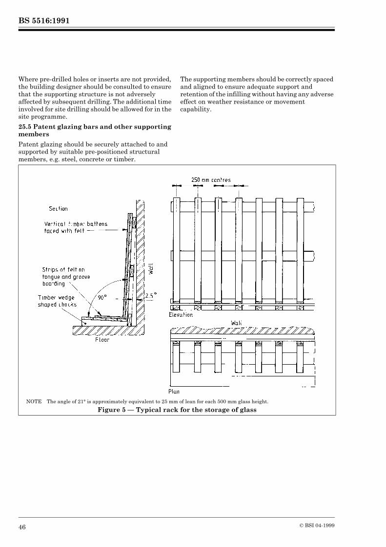
BS 5516:1991
46 © BSI 04-1999
Where pre-drilled holes or inserts are not provided, the building designer should be consulted to ensure that the supporting structure is not adversely affected by subsequent drilling. The additional time involved for site drilling should be allowed for in the site programme.
25.5 Patent glazing bars and other supporting members
Patent glazing should be securely attached to and supported by suitable pre-positioned structural members, e.g. steel, concrete or timber.
The supporting members should be correctly spaced and aligned to ensure adequate support and retention of the infilling without having any adverse effect on weather resistance or movement capability.
NOTE The angle of 21° is approximately equivalent to 25 mm of lean for each 500 mm glass height.
Figure 5 — Typical rack for the storage of glass
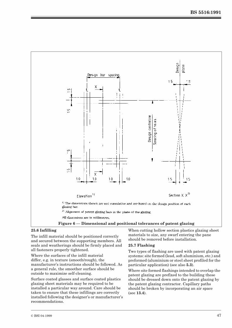
BS 5516:1991
© BSI 04-1999 47
25.6 Infilling
The infill material should be positioned correctly and secured between the supporting members. All seals and weatherings should be firmly placed and all fasteners properly tightened.Where the surfaces of the infill material differ, e.g. in texture (smooth/rough), the manufacturer’s instructions should be followed. As a general rule, the smoother surface should be outside to maximize self-cleaning.Surface coated glasses and surface coated plastics glazing sheet materials may be required to be installed a particular way around. Care should be taken to ensure that these infillings are correctly installed following the designer’s or manufacturer’s recommendations.
When cutting hollow section plastics glazing sheet materials to size, any swarf entering the pane should be removed before installation.
25.7 Flashing
Two types of flashing are used with patent glazing systems: site formed (lead, soft aluminium, etc.) and preformed (aluminium or steel sheet profiled for the particular application) (see also 5.3).Where site formed flashings intended to overlap the patent glazing are prefixed to the building these should be dressed down onto the patent glazing by the patent glazing contractor. Capillary paths should be broken by incorporating an air space (see 13.4).
Figure 6 — Dimensional and positional tolerances of patent glazing
BS 5516:1991
48 © BSI 04-1999
When dressing down site formed flashings, great care should be taken to avoid damaging the infill material and, where necessary, retaining clips should be used to restrain the free edges of the flashing against wind uplift. Lapped joints should overlap by at least 100 mm.Preformed flashings should be fixed with lapped or butt joints and sealed. Butt straps at least 100 mm wide should be used with butt joints.
25.8 Ancillary components
Where local atmospheric conditions are likely to promote a reaction between dissimilar metals, isolation material should be used between the untreated surfaces. (See also 20.2).
25.9 Protective masking
If materials are supplied with masking, this should be peeled back sufficiently to prevent entrapment during installation. Masking should be completely removed as soon as practically possible after installation, as environmental effects will make it increasingly difficult to remove. If any masking is to remain for a longer period of time, the supplier of the protected item should be consulted.NOTE On plastics glazing sheet materials a time limit is sometimes printed on the masking.
BS 5516:1991
© BSI 04-1999 49
Section 5. Maintenance
26 Access for maintenance and cleaning26.1 General
Those engaged on maintenance work should use suitable equipment.NOTE Attention is drawn to the Construction (Working Places) Regulations 1966, SI 64.Equipment should be so constructed that the weight of operatives is well distributed and over at least two patent glazing bars. Experienced operatives, who know how and where to apply their weight, should be employed. Patent glazing should never be stood or walked upon without the use of crawling boards, etc.
26.2 Reason for access
There are several reasons why direct access should be provided to areas of sloping or vertical patent glazing, both to internal and to external surfaces. Primarily these are inspection, cleaning and repair or renewal.
26.3 Temporary access
Temporary access, if required, may be attained by the use of ladders, crawling boards and scaffolding of various forms suitable for the particular type of building and the location of the patent glazing. Such forms of access should be removed shortly after use.Ladders and crawling boards may be used safely without imposing any loading on the patent glazing provided that they are supported at a purlin or other structural member. Spreader boards should be properly secured and should rest on at least two patent glazing bars. On sloping patent glazing, stops may need to be provided on the patent glazing bars to locate crawling boards, etc. and to prevent them slipping. Maintenance loads should never be carried directly by the infilling. Examples of the use of ladders and crawling boards are shown in Figure 7.Temporary access may also be gained through the use of specialist systems, such as manual or powered cradles or gantries. Motorized working platforms are particularly useful on the inside of a building provided that there is good access and sufficient room to manoeuvre. They may also be effectively used outside. Care should always be exercised to ensure that firm and level areas are provided from which to operate.
26.4 Permanent access
Systems of permanent access may be either fixed or moving platforms on some form of tracking, re-locatable within a pre-set pattern. Walkways or platforms may be designed as an integral part of the patent glazing system, but preferably should be completely independent of it. Such systems may be designed to suit sloping or vertical patent glazing and allow for access to external and/or internal surfaces.
27 InspectionPeriodic visual inspection of patent glazing should be carried out by those responsible for the maintenance of the building.Particular attention should be given to joint seals and junctions between different materials, moving parts such as doors, opening windows and ventilators, etc.The frequency of inspections/cleaning for a particular component or finish may also be determined by the requirements of the terms and conditions of a manufacturer’s warranty.Where it is known that there is a particular risk from atmospheric pollution, e.g. from certain production processes, or close proximity to the sea, more frequent inspection may be necessary.
28 Cleaning28.1 General
Regular cleaning to remove atmospheric grime and pollution will maintain the appearance, durability and performance of patent glazing. Cleaning therefore contributes considerably to the effective life of the patent glazing. The frequency of cleaning of internal as well as external surfaces depends upon the following:
a) the current use being made of the building;b) the particular situation of the patent glazing on the building;c) the building location and the local environmental conditions;d) the type of infill material, its surface texture and finish;e) the materials used for supporting members, flashings, ancillary components and their surface texture and finish;f) the attitude of the client/owner to the general appearance and maintenance of the building.
28.2 Infilling
Transparent or translucent infilling should be cleaned regularly and at time intervals depending upon the accumulation of dirt.
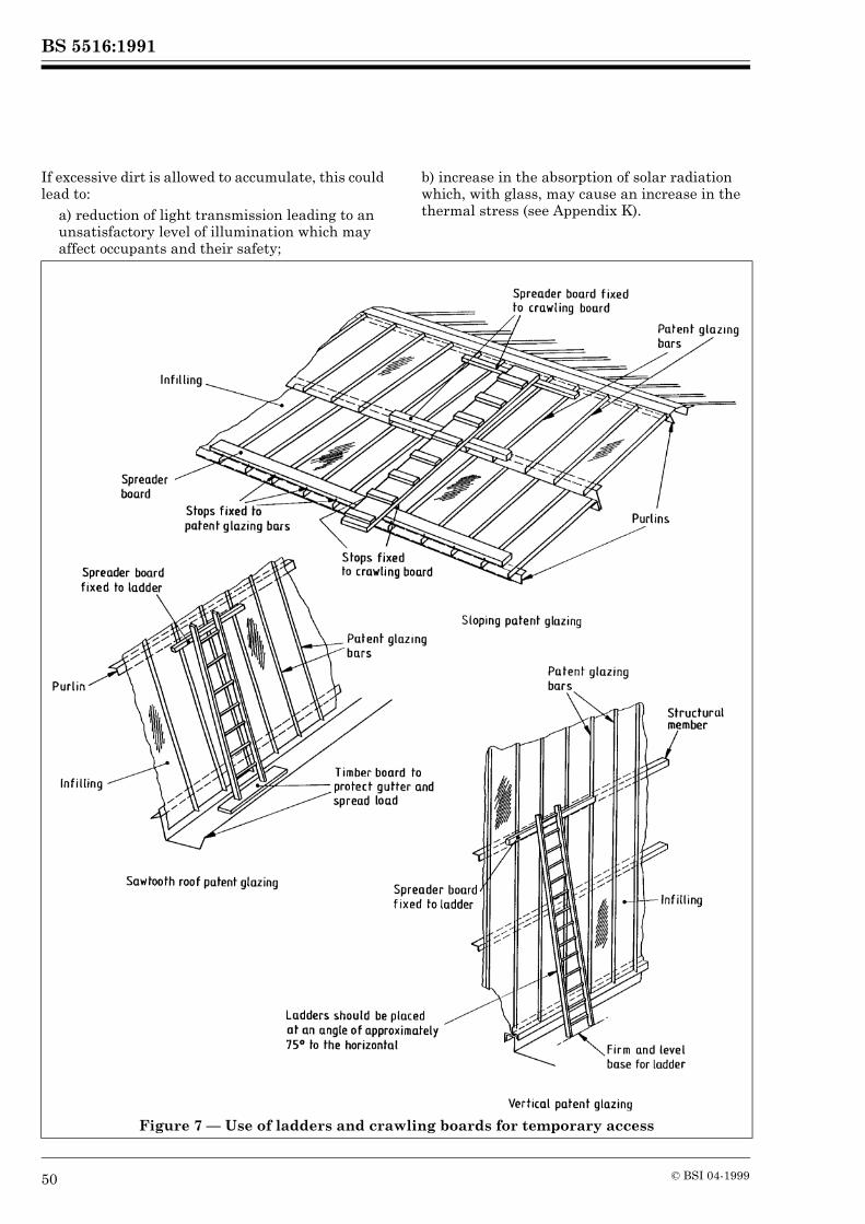
BS 5516:1991
50 © BSI 04-1999
If excessive dirt is allowed to accumulate, this could lead to:
a) reduction of light transmission leading to an unsatisfactory level of illumination which may affect occupants and their safety;
b) increase in the absorption of solar radiation which, with glass, may cause an increase in the thermal stress (see Appendix K).
Figure 7 — Use of ladders and crawling boards for temporary access
BS 5516:1991
© BSI 04-1999 51
28.3 Supporting members, flashings and ancillary components
During cleaning, care should be taken not to disturb any weatherings including wings, caps or flashings, or to dislodge any other ancillary components.Outlets from water channels should be cleared as necessary.
28.4 Cleaning materials
A solution of mild detergent in water, applied with a clean soft non-abrasive cloth, followed by a thorough clean water rinse should be used for routine cleaning. Care should be exercised to avoid rubbing dirt into any surface.
The removal of stains and marks, other than those which are removed by the method described above, should be discussed with the manufacturer of the material to be cleaned.For treatment of specific surface finishes to metal, reference should be made to BS 6270-34).
29 Other maintenanceAny damaged or missing components located during period inspection should be replaced as soon as possible, and any loose items secured as necessary.Where replacement or repair work is necessary, this should preferably be carried out by the patent glazing contractor responsible for the original installation.
4) In preparation.
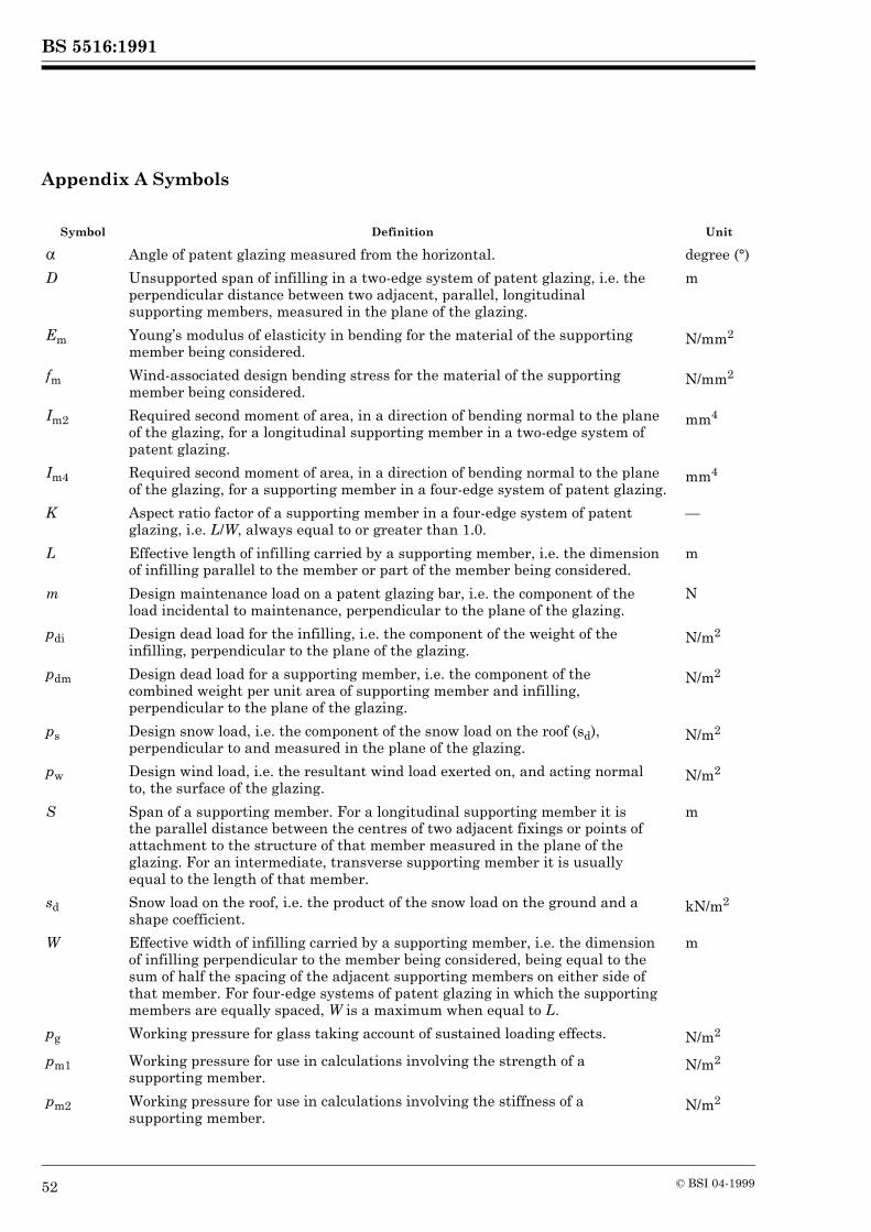
BS 5516:1991
52 © BSI 04-1999
Appendix A Symbols
Symbol Definition Unit
! Angle of patent glazing measured from the horizontal. degree (°)
D Unsupported span of infilling in a two-edge system of patent glazing, i.e. the perpendicular distance between two adjacent, parallel, longitudinal supporting members, measured in the plane of the glazing.
m
Em Young’s modulus of elasticity in bending for the material of the supporting member being considered.
N/mm2
fm Wind-associated design bending stress for the material of the supporting member being considered.
N/mm2
Im2 Required second moment of area, in a direction of bending normal to the plane of the glazing, for a longitudinal supporting member in a two-edge system of patent glazing.
mm4
Im4 Required second moment of area, in a direction of bending normal to the plane of the glazing, for a supporting member in a four-edge system of patent glazing.
mm4
K Aspect ratio factor of a supporting member in a four-edge system of patent glazing, i.e. L/W, always equal to or greater than 1.0.
—
L Effective length of infilling carried by a supporting member, i.e. the dimension of infilling parallel to the member or part of the member being considered.
m
m Design maintenance load on a patent glazing bar, i.e. the component of the load incidental to maintenance, perpendicular to the plane of the glazing.
N
pdi Design dead load for the infilling, i.e. the component of the weight of the infilling, perpendicular to the plane of the glazing.
N/m2
pdm Design dead load for a supporting member, i.e. the component of the combined weight per unit area of supporting member and infilling, perpendicular to the plane of the glazing.
N/m2
ps Design snow load, i.e. the component of the snow load on the roof (sd), perpendicular to and measured in the plane of the glazing.
N/m2
pw Design wind load, i.e. the resultant wind load exerted on, and acting normal to, the surface of the glazing.
N/m2
S Span of a supporting member. For a longitudinal supporting member it is the parallel distance between the centres of two adjacent fixings or points of attachment to the structure of that member measured in the plane of the glazing. For an intermediate, transverse supporting member it is usually equal to the length of that member.
m
sd Snow load on the roof, i.e. the product of the snow load on the ground and a shape coefficient.
kN/m2
W Effective width of infilling carried by a supporting member, i.e. the dimension of infilling perpendicular to the member being considered, being equal to the sum of half the spacing of the adjacent supporting members on either side of that member. For four-edge systems of patent glazing in which the supporting members are equally spaced, W is a maximum when equal to L.
m
pg Working pressure for glass taking account of sustained loading effects. N/m2
pm1 Working pressure for use in calculations involving the strength of a supporting member.
N/m2
pm2 Working pressure for use in calculations involving the stiffness of a supporting member.
N/m2
BS 5516:1991
© BSI 04-1999 53
Appendix B Wind load
A summary of the method for determining wind loads, as given in CP 3:Chapter V-2, which may be used when designing patent glazing is given below.The maximum 3 s gust speed likely to be exceeded on average only once in 50 years at a height of 10 m above ground in open, level country is determined for the district where the building is located. This basic wind speed is multiplied by appropriate factors to take account of topography, ground roughness with height above ground of the top of the patent glazing, building life and wind direction to give the design wind speed.The design wind speed is then converted to a dynamic pressure, expressed in newtons per square metre, from the standard relationship given in SI units. The maximum inward (positive) pressure and the maximum outward (negative) pressure exerted at any point on the surface of the patent glazing are obtained by multiplying the resulting dynamic pressure by appropriate pressure coefficients based on the worst possible combination of the patent glazing’s being subjected simultaneously to positive pressure on one surface and negative pressure on the other.For external walls and roofs of clad buildings the value of these pressure coefficients is the difference between an external pressure coefficient which is dependent on the shape and size of the building, wind direction and the position of the patent glazing under consideration, and an internal pressure coefficient evaluated on the basis of the size and distribution of openings in the building. For roofs of free-standing, open-sided canopies combined overall pressure coefficients are used depending on the shape of the roof, the degree of obstruction under the canopy and the position of the patent glazing under consideration.
A negative sign profixing a pressure coefficient indicates a suction (negative pressure) as distinct from a positive pressure and the design wind loads pw thus derived, which may be both positive and negative, act in a direction normal to the surface of the patent glazing.It may be noted that extremes of internal pressure may arise when a building is only partially clad during its construction. The building designer will be aware of the proposed sequence of construction and should consider the problem so that the most vulnerable conditions of partial cladding and dangerous structural shapes are avoided.
Appendix C Snow load
A summary of the method for determining snow loads, as given in BS 6399-3, which may be used when designing patent glazing is given below.The load intensity of undrifted snow at ground level likely to be exceeded on average only once in 50 years at an altitude of 100 m in a sheltered area is determined for the district where the building is located. This basic snow load on the ground is adjusted on a regional basis for locations whose altitude is above 100 m and to take account of building life to give the characteristic snow load on the ground.
pp Working pressure for plastics glazing sheet material taking account of sustained loading effects.
N/m2
ym2 Limiting deflection, normal to the plane of the glazing, for a supporting member in a two-edge system of patent glazing.
mm
ym4 Limiting deflection, normal to the plane of the glazing, for a supporting member in a four-edge system of patent glazing.
mm
Zm2 Required modulus of section, in a direction of bending normal to the plane of the glazing, for a longitudinal supporting member in a two-edge system of patent glazing.
mm3
Zm4 Required modulus of section, in a direction of bending normal to the plane of the glazing, for a supporting member in a four-edge system of patent glazing.
mm3
Symbol Definition Unit
BS 5516:1991
54 © BSI 04-1999
The snow load on the roof is obtained by multiplying the characteristic snow load on the ground by an appropriate shape coefficient based on the worst load case applicable. The value of this shape coefficient is dependent on the external shape of the roof, the position and height of any surrounding roofs and the position of the patent glazing under consideration. Two primary loading conditions should be considered: that resulting from a uniform layer of snow and that resulting from an uneven distribution of snow. Uneven distribution may result from the transport of snow by the wind from one side of a roof to the other side or from the accumulation of drifted snow against vertical obstructions and in valleys.The resultant snow load on the roof is assumed to act vertically and refer to a horizontal projection of the area of the roof. For the derivation of the design snow load ps (in N/m2) the component of the snow load on the roof perpendicular to and measured in the plane of the glazing is required. This may be found from the following equation:
ps = sd × 103 cos2 !
wheresd is the snow load on the roof (in kN/m2).
NOTE It is recommended that load cases involving local drifting of snow are treated as exceptional snow loads because of the rarity with which they are expected to occur. In such cases, the value obtained for the snow load on the roof, sd, may be multiplied by a suitable factor when deriving design snow load, ps for use in calculations involving the strength of supporting members and infilling. Suitable factors are 0.75 for supporting members and 0.8 for infilling.
Appendix D Dead load (self-weight)
Dead load for a supporting member should be based on the combined weight of the supporting member and of the infilling (both panes in double glazing). Dead load for the infilling alone should be based on the weight of the infill material only, the mass of hermetically sealed double glazing units and of laminated glass being taken as the sum of the nominal mass of the individual glasses. For the derivation of design dead load for a supporting member, pdm (in N/m2), and for the infilling, pdi (in N/m2), the component of the weights perpendicular to the plane of the glazing is required and use may be made of the following equations:
pdm = gim cos !
pdi = gi cos !
wheregim is the weight per unit area of the supporting member and infilling (in N/m2);gi is the weight per unit area of the infilling (in N/m2).
NOTE (Kilogram mass per square metre) × 9.81 = weight per unit area (N/m2).
Appendix E Maintenance load
Where maintenance loads may have to be carried by the patent glazing suitable provision should be made in the design.The assessment of loads incidental to maintenance requires assumptions on the nature of the loads and how they are likely to be applied. For normal, routine maintenance, such as cleaning or repair work, the patent glazing bars (longitudinal supporting members) should be capable of sustaining with safety to themselves and to the infilling a central point load sufficient to represent the effect of a ladder or crawling board leaning against or resting on at least two patent glazing bars and supporting the weight of a man. On sloping patent glazing, the maintenance load is unlikely to be other than in an inward direction; with vertical patent glazing, the load might be inward (positive) or outward (negative). Based on these assumptions, the following central point load on each patent glazing bar has been estimated:
a) for sloping patent glazing, a vertical load of 695 N;b) for vertical patent glazing, a horizontal load of 172 N.
For the derivation of design maintenance load m (in N), the component of the load perpendicular to the plane of the glazing is required. This may be obtained from the following equations:
1) for sloping patent glazing, m = 695 × cos !;2) for vertical patent glazing, m = 172/sin !.
Maintenance loads should never be carried directly by the infilling.Where other more severe maintenance loads are anticipated, suitable provision should be made and the patent glazing contractor should be provided with the necessary information at the initial design stage (see 3.2).
Appendix F Determination of working pressures for patent glazing
F.1 GeneralDepending upon the particular situation, patent glazing may be exposed to more than one of the types of loading described in 10.3. Some of these loads may act simultaneously, either in the same direction or in opposite directions. In determining working pressures for patent glazing, an assessment of their effects should be carried out in such a way as to account for all possible loading combinations that are likely to occur in service.

BS 5516:1991
© BSI 04-1999 55
For safety reasons, maintenance should not be carried out in strong winds or when there is much snow lying on the patent glazing and it is unnecessary therefore to treat maintenance load as additive when considering wind load and snow load. For similar reasons, the clearing of snow from roofs containing fragile or non-loadbearing materials, especially glass, is not recommended. Furthermore, partial removal of snow may adversely affect the structural stability of the roof.All the design loads discussed in Appendix B to Appendix E have been expressed finally in terms of the design loads perpendicular to the plane of the glazing. The various combinations of design loads that have to be considered may now be expressed algebraically, with a positive or a negative sign prefixing the design wind load pw to distinguish between inward (+) and outward (–) pressure.F.2 Sloping patent glazingFor sloping patent glazing, the combinations of positive loads acting inwards that usually have to be considered are thus: for supporting members, ( + pw + ps + pdm) and for the infilling ( + pw + ps + pdi) and, if required to take account of maintenance load, for patent glazing bars a combination of pdm and m. On those parts of the building subject to wind suction, the maximum negative loads acting outwards that result are the following combinations: for supporting members ( – pw + pdm) and for the infilling ( – pw + pdi).F.3 Vertical patent glazingFor vertical patent glazing, the magnitude of loads incidental to maintenance is likely to be small compared with the probable maximum wind loading both positive and negative and, as it is assumed that extensive maintenance would not be carried out in very windy conditions, any possible maintenance loads can usually be ignored. However, there may be instances, for example in sheltered situations with very low wind loading, where the combination of maintenance load and dead load may give rise to critical loading and these should be considered in determining working pressure for patent glazing bars. Generally, therefore, for vertical patent glazing the maximum resultant positive loads acting inwards are usually the following combinations: for supporting members ( + pw + pdm) and for the infilling ( + pw + pdi) and, if required to take account of maintenance load, for patent glazing bars a combination of pdm and m. However, where sliding or drifting snow is likely to accumulate against vertical patent glazing, then the resultant snow load should be taken into account in determining the maximum positive loads acting inwards.
On those parts of the building subject to wind suction, the maximum negative loads acting outwards are likely to be the following combinations: for supporting members ( – pw + pdm) and for the infilling ( – pw + pdi). In addition, self-weight should also be considered as a dead load acting downwards in the plane of the glazing in respect of transverse supporting members and fixings.
Appendix G Determination of working pressures for supporting members
As noted in 10.6.1.2, permissible stresses due to 3 s gust wind loading may be increased by one-third. When considering snow load and dead load and, if required, maintenance load in conjunction with wind load in determining working pressures for use in calculations involving the strength of supporting members, it may therefore be convenient to design to a single, wind-associated stress value and adjust the sustained loads by multiplying them by a factor of 1.33. This factor is not applied to the dead load where self-weight serves only to diminish the effect of a negative wind pressure. No such adjustment is necessary in determining working pressures for use in calculations involving the stiffness of supporting members.As any maintenance load on patent glazing bars is likely to be a concentrated one and not distributed like wind, snow and self-weight, it is convenient to consider the combination of dead load and maintenance load separately when calculating the required geometric properties of section for longitudinal supporting members (see Appendix H).Applying the adjustment for sustained loads to the combinations of design loads (excluding maintenance load) considered in Appendix F, the following expressions are obtained.
a) For sloping patent glazing:+ pw + 1.33(ps + pdm)
and if a negative value for pw is derived, i.e. wind suction conditions:– pw + pdm
b) For vertical patent glazing:+ pw + 1.33pdm
and if a negative value for pw is derived, i.e. wind suction conditions:– pw + pdm
In a) and b), to take account of windless conditions, when no positive value for pw is derived, zero should be substituted for + pw.
BS 5516:1991
56 © BSI 04-1999
In a), design snow load ps is assumed to be uniformly distributed. In the case of drifting snow, the design snow load on a supporting member may not be uniformly distributed. In such cases, it may be appropriate to consider snow load separately from wind load and dead load in determining working pressures for supporting members (see H.2).Each load case should be considered and whichever of the resultant values is numerically the greater should be taken as the operative working pressure pm1 for the particular situation of the patent glazing. The values thus obtained are for use in calculations involving the strength of supporting members, such as are shown in Appendix H. In addition, when considering the strength requirements for transverse supporting members, the component of the load due to self-weight parallel to the plane of the glazing should also be multiplied by a factor of 1.33.Working pressures for use in calculations involving the stiffness of supporting members, such as are shown in Appendix H, are determined in a similar way but here there is no need for the inclusion of a factor of 1.33 for sustained loads. The resultant values thus obtained are distinguished by the notation pm2.
Appendix H Determination of required geometric properties of section for supporting members
H.1 Normal conditions of loading and supportH.1.1 GeneralAssuming that the design loads act in the direction of an axis of symmetry of the cross section of a supporting member which is simply supported at both ends then, ignoring the contribution to stiffness made by the infilling, the required geometric properties of section about the neutral axis, in a direction of bending normal to the plane of the glazing, may be obtained from the formulae given in H.1.2 and H.1.3 for an intermediate, parallel supporting member.H.1.2 Two-edge patent glazingFor distributed loads pw, ps and pdm, the modulus of section Zm2 (in mm3) is given by
and the second moment of area Im2 (in mm4) is given by
If required, to take account of maintenance load, the values for Zm2 and Im2 for the combination of dead load pdm and maintenance load m on longitudinal supporting members may be re-calculated as follows.The component of the modulus of section Zm2 (in mm3) corresponding to the dead load is given by
The component of the modulus of section Zm2 (in mm3) corresponding to the maintenance load is given by
Components (3) and (4) are added together to obtain the total required value for Zm2, the result is compared with that given by equation (1) and whichever is the greater value is taken to be the minimum requirement.The component of the second moment of area Im2 (in mm4) corresponding to the dead load is given by
The component of the second moment of area Im2 (in mm4) corresponding to the maintenance load is given by
Components (5) and (6) are added together to obtain the total required value for Im2, the result is compared with that given by equation (2) and whichever is the greater value is taken to be the minimum requirement.In each case, both Zm2 and Im2 values should be satisfied for a supporting member to be considered suitable.The formulae given in H.1.2, which are for simply supported, single-span members, may be used for continuous members of two or more approximately equal spans in which case the effective length of infilling L should be taken as equal to the span S of the supporting member. Further consideration should be given where reduction of section or concentration of loading occurs in regions of critical stress in a member.
(1)
(2)
(3)
(4)
(5)
(6)
BS 5516:1991
© BSI 04-1999 57
H.1.3 Four-edge patent glazing (parallel supporting members equally spaced)To make allowance for the way in which the uniform loads are distributed from the infilling to all four supporting members and for the aspect ratio factor of the supporting member under consideration, the moment and deflection coefficients, given in formulae (1), (2), (3) and (5), may be modified and the following equations derived.For distributed loads pw, ps and pdm, the modulus of section Zm4 (in mm3) is given by
and the second moment of area Im4 (in mm4) is given by
If required, to take account of maintenance load, the values for Zm4 and Im4 for the combination of dead load pdm and maintenance load m on longitudinal supporting members may be re-calculated as follows.The component of the modulus of section Zm4 (in mm3) corresponding to the dead load is given by
The component of the modulus of section Zm4 (in mm3) corresponding to the maintenance load is given by
Components (9) and (10) are added together to obtain the total required value for Zm4, the result is compared with that given by equation (7) and whichever is the greater value is taken to be the minimum requirement.The component of the second moment of area Im4 (in mm4) corresponding to the dead load is given by
The component of the second moment of area Im4 (in mm4) corresponding to the maintenance load is given by
Components (11) and (12) are added together to obtain the total required value for Im4, the result is compared with that found in equation (8) and whichever is the greater value is taken to be the minimum requirement.In each case, both Zm4 and Im4 values should be satisfied for a supporting member to be considered suitable.The formulae given in H.1.3 are valid for longitudinal supporting members only when transverse supporting members occur at both points of attachment to the structure. Otherwise, the formulae given in H.1.2 should be used but ym4 should be substituted for ym2.H.2 Other conditions of loading and supportFor conditions of loading and support, other than as described in H.1, or where insufficient information is available to proceed with the design in accordance with this standard, or where precise calculations are required, a detailed structural analysis should be undertaken.
Appendix J Plastics glazing sheet materials
J.1 GeneralThe properties of plastics glazing sheet materials differ considerably from other infill materials in a number of significant ways. These properties affect the following aspects of a patent glazing system:
a) allowances for expansion and contraction of the infilling (affected by the coefficients of expansion due to temperature change and moisture absorption);b) edge cover provided by supporting members (affected by the flexing of the infilling under load, coefficients of expansion and, in the case of hollow section sheets, the profile of the sheet);c) double glazing (affected by gas and water vapour permeability properties);d) sealing and glazing materials (affected by the need for chemical compatibility with parts of the system in contact with the infilling);e) flashings and other weatherings (affected by the flexing of the infilling under load and the coefficients of expansion).
(7)
(8)
(9)
(10)
(11)
(12)
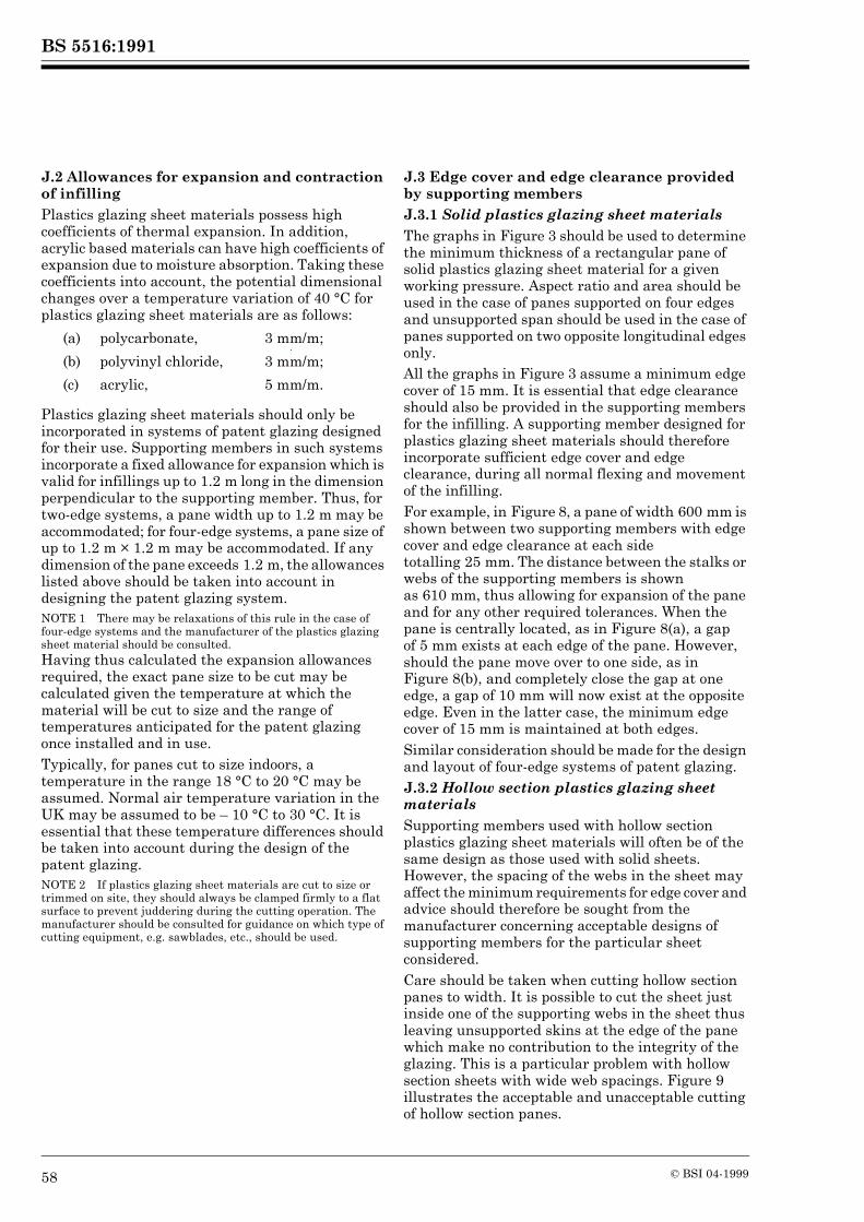
BS 5516:1991
58 © BSI 04-1999
J.2 Allowances for expansion and contraction of infillingPlastics glazing sheet materials possess high coefficients of thermal expansion. In addition, acrylic based materials can have high coefficients of expansion due to moisture absorption. Taking these coefficients into account, the potential dimensional changes over a temperature variation of 40 °C for plastics glazing sheet materials are as follows:
Plastics glazing sheet materials should only be incorporated in systems of patent glazing designed for their use. Supporting members in such systems incorporate a fixed allowance for expansion which is valid for infillings up to 1.2 m long in the dimension perpendicular to the supporting member. Thus, for two-edge systems, a pane width up to 1.2 m may be accommodated; for four-edge systems, a pane size of up to 1.2 m × 1.2 m may be accommodated. If any dimension of the pane exceeds 1.2 m, the allowances listed above should be taken into account in designing the patent glazing system.NOTE 1 There may be relaxations of this rule in the case of four-edge systems and the manufacturer of the plastics glazing sheet material should be consulted.Having thus calculated the expansion allowances required, the exact pane size to be cut may be calculated given the temperature at which the material will be cut to size and the range of temperatures anticipated for the patent glazing once installed and in use.Typically, for panes cut to size indoors, a temperature in the range 18 °C to 20 °C may be assumed. Normal air temperature variation in the UK may be assumed to be – 10 °C to 30 °C. It is essential that these temperature differences should be taken into account during the design of the patent glazing.NOTE 2 If plastics glazing sheet materials are cut to size or trimmed on site, they should always be clamped firmly to a flat surface to prevent juddering during the cutting operation. The manufacturer should be consulted for guidance on which type of cutting equipment, e.g. sawblades, etc., should be used.
J.3 Edge cover and edge clearance provided by supporting membersJ.3.1 Solid plastics glazing sheet materialsThe graphs in Figure 3 should be used to determine the minimum thickness of a rectangular pane of solid plastics glazing sheet material for a given working pressure. Aspect ratio and area should be used in the case of panes supported on four edges and unsupported span should be used in the case of panes supported on two opposite longitudinal edges only.All the graphs in Figure 3 assume a minimum edge cover of 15 mm. It is essential that edge clearance should also be provided in the supporting members for the infilling. A supporting member designed for plastics glazing sheet materials should therefore incorporate sufficient edge cover and edge clearance, during all normal flexing and movement of the infilling.For example, in Figure 8, a pane of width 600 mm is shown between two supporting members with edge cover and edge clearance at each side totalling 25 mm. The distance between the stalks or webs of the supporting members is shown as 610 mm, thus allowing for expansion of the pane and for any other required tolerances. When the pane is centrally located, as in Figure 8(a), a gap of 5 mm exists at each edge of the pane. However, should the pane move over to one side, as inFigure 8(b), and completely close the gap at one edge, a gap of 10 mm will now exist at the opposite edge. Even in the latter case, the minimum edge cover of 15 mm is maintained at both edges.Similar consideration should be made for the design and layout of four-edge systems of patent glazing.J.3.2 Hollow section plastics glazing sheet materialsSupporting members used with hollow section plastics glazing sheet materials will often be of the same design as those used with solid sheets. However, the spacing of the webs in the sheet may affect the minimum requirements for edge cover and advice should therefore be sought from the manufacturer concerning acceptable designs of supporting members for the particular sheet considered.Care should be taken when cutting hollow section panes to width. It is possible to cut the sheet just inside one of the supporting webs in the sheet thus leaving unsupported skins at the edge of the pane which make no contribution to the integrity of the glazing. This is a particular problem with hollow section sheets with wide web spacings. Figure 9 illustrates the acceptable and unacceptable cutting of hollow section panes.
(a) polycarbonate, 3 mm/m;
(b) polyvinyl chloride, 3 mm/m;
(c) acrylic, 5 mm/m.
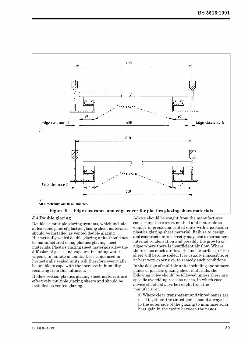
BS 5516:1991
© BSI 04-1999 59
J.4 Double glazingDouble or multiple glazing systems, which include at least one pane of plastics glazing sheet materials, should be installed as vented double glazing. Hermetically sealed double glazing units should not be manufactured using plastics glazing sheet materials. Plastics glazing sheet materials allow the diffusion of gases and vapours, including water vapour, in minute amounts. Dessicants used in hermetically sealed units will therefore eventually be unable to cope with the increase in humidity resulting from this diffusion.Hollow section plastics glazing sheet materials are effectively multiple glazing sheets and should be installed as vented glazing.
Advice should be sought from the manufacturer concerning the correct method and materials to employ in preparing vented units with a particular plastics glazing sheet material. Failure to design and construct units correctly may lead to permanent internal condensation and possibly the growth of algae where there is insufficient air flow. Where there is too much air flow, the inside surfaces of the sheet will become soiled. It is usually impossible, or at best very expensive, to remedy such conditions.In the design of multiple units including one or more panes of plastics glazing sheet materials, the following rules should be followed unless there are specific overriding reasons not to, in which case advice should always be sought from the manufacturer.
a) Where clear transparent and tinted panes are used together, the tinted pane should always be to the outer side of the glazing to minimize solar heat gain in the cavity between the panes.
Figure 8 — Edge clearance and edge cover for plastics glazing sheet materials
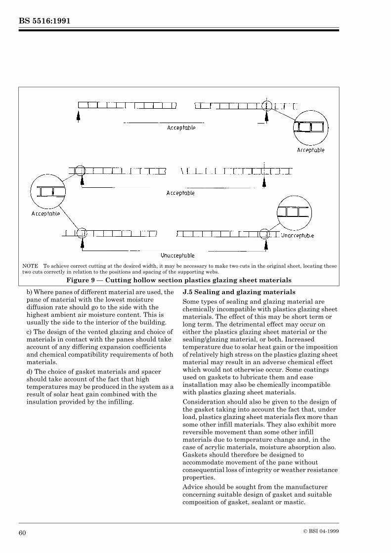
BS 5516:1991
60 © BSI 04-1999
b) Where panes of different material are used, the pane of material with the lowest moisture diffusion rate should go to the side with the highest ambient air moisture content. This is usually the side to the interior of the building.c) The design of the vented glazing and choice of materials in contact with the panes should take account of any differing expansion coefficients and chemical compatibility requirements of both materials.d) The choice of gasket materials and spacer should take account of the fact that high temperatures may be produced in the system as a result of solar heat gain combined with the insulation provided by the infilling.
J.5 Sealing and glazing materialsSome types of sealing and glazing material are chemically incompatible with plastics glazing sheet materials. The effect of this may be short term or long term. The detrimental effect may occur on either the plastics glazing sheet material or the sealing/glazing material, or both. Increased temperature due to solar heat gain or the imposition of relatively high stress on the plastics glazing sheet material may result in an adverse chemical effect which would not otherwise occur. Some coatings used on gaskets to lubricate them and ease installation may also be chemically incompatible with plastics glazing sheet materials.Consideration should also be given to the design of the gasket taking into account the fact that, under load, plastics glazing sheet materials flex more than some other infill materials. They also exhibit more reversible movement than some other infill materials due to temperature change and, in the case of acrylic materials, moisture absorption also. Gaskets should therefore be designed to accommodate movement of the pane without consequential loss of integrity or weather resistance properties.Advice should be sought from the manufacturer concerning suitable design of gasket and suitable composition of gasket, sealant or mastic.
NOTE To achieve correct cutting at the desired width, it may be necessary to make two cuts in the original sheet, locating these two cuts correctly in relation to the positions and spacing of the supporting webs.
Figure 9 — Cutting hollow section plastics glazing sheet materials
BS 5516:1991
© BSI 04-1999 61
J.6 Flashings and other weatheringsFlashings and weatherings should be chemically compatible with plastics glazing sheet materials and be designed to allow expansion and contraction of the pane while retaining their weather performance.Because plastics glazing sheet materials flex more under load than some other infill materials, preformed rigid flashings, which are not permanently deflected by flexing panes, should be used. In addition, the pane should be supported on the opposite side from the flashing to prevent deflection of the pane away from the flashing when under load.
Appendix K Thermal stress in glass
K.1 AssessmentKnowledge of the radiation to which the glass is to be subjected and the thermal capabilities of the glass are necessary for the assessment of the thermal stress in glass. One method of assessment is by determining the solar radiation intensity on the glass surface and the air temperature range applicable to the location of the building. These, together with the heat transfer coefficients and the glass absorption, allow determination of the appropriate basic temperature difference between the central area of the glass and its edge. This difference is related to the thermal stress and then modified for the type of patent glazing system, taking account of extraneous effects resulting from shading devices (curtains, blinds, etc.), back-ups or close proximity to heaters and the like, to derive a stress for actual service conditions.The resultant service stress should then be compared with the design stress for the glass. If on comparison the service stress is less than or equal to the design stress, the glass and glazing system may be accepted as thermally safe provided that the edges of the glass are of the appropriate quality.K.2 Glass edge qualityBecause the usual mode of thermal breakage of glass is by the action of tensile stress located in and parallel to an edge, the breaking stress of the glass is mainly dependent on the edge quality and the extent and position of flaws. The condition of the glass edge is therefore extremely important.
A clean wheel-cut edge is the most satisfactory. Where treated edges are required, arrises should be created by a wet process, working parallel to the edge and not across the thickness, and the design implications of such an action should be examined.Glasses should not be nipped to size and any panes with shelled or vented edges should not be accepted for use in orientations subject to direct sunlight.Care should be taken when using wired glass, as there are problems in producing high quality cut edges on wired glass. Also, allowing the edges of the glass to remain in contact with moisture may produce rusting/corrosion of the wires which may lead to the formation of edge defects. Attention should be paid to the likelihood of this and account taken during the thermal safety assessment.K.3 Effect of dirtIf glass is allowed to become very dirty, either internally or externally, the dirt will absorb solar radiation. This may result in glass breakage, particularly where wired glass is used; the accumulation of dirt should therefore be avoided by regular cleaning. Toughened glass is not subjected to the same risk as it can withstand large temperature differentials.K.4 Other considerationsK.4.1 Reflective treatmentsUsing a treatment given in 16.3.3 will increase the capacity of the glass to absorb heat and hence increase the likelihood of thermal breakage.K.4.2 Solar control plastics filmsWhere the application of a solar control film to a glass is being considered, advice should be sought from the manufacturer of the film on the effect of any additional thermal stress likely to be induced in the glass.K.4.3 OverhangsIn sloping patent glazing there is often a need to have an overhang of the bottom edge of the glass as a means of producing the required weather resistance.Care should be taken in designing these overhangs to reduce/minimize the effect on the thermal stress produced within the glass.K.4.4 Toughened glassWhen toughened glass is being used, thermal safety need not be considered.
BS 5516:1991
62 © BSI 04-1999
Publication(s) referred to
BS 476, Fire tests on building materials and structures. BS 476-3, External fire exposure roof test. BS 476-4, Non-combustibility test for materials. BS 476-6, Method of test for fire propagation for products. BS 476-7, Method for classification of the surface spread of flame of products. BS 476-20, Method for determination of the fire resistance of elements of construction (general principles). BS 476-22, Methods for determination of the fire resistance of non-loadbearing elements of construction. BS 729, Specification for hot dip galvanized coatings on iron and steel articles. BS 952, Glass for glazing. BS 952-1, Classification. BS 1178, Specification for milled lead sheet for building purposes. BS 1449, Steel plate, sheet and strip. BS 1449-1, Specification for carbon and carbon-manganese plate, sheet and strip. BS 1449-2, Specification for stainless and heat-resisting steel plate, sheet and strip. BS 1470, Specification for wrought aluminium and aluminium alloys for general engineering purposes: plate, sheet and strip. BS 1473, Specification for wrought aluminium and aluminium alloys for general engineering purposes — rivet, bolt and screw stock. BS 1474, Specification for wrought aluminium and aluminium alloys for general engineering purposes: bars, extruded round tubes and sections. BS 1615, Method for specifying anodic oxidation coatings on aluminium and its alloys. BS 2569, Specification for sprayed metal coatings. BS 2569-1, Protection of iron and steel by aluminium and zinc against atmospheric corrosion. BS 2571, Specification for general-purpose flexible PVC compounds for moulding and extrusion. BS 2874, Specification for copper and copper alloy rods and sections (other than forging stock). BS 2989, Specification for continuously hot-dip zinc coated and iron-zinc alloy coated steel: wide strip, sheet/plate and slit wide strip. BS 3382, Specification for electroplated coatings on threaded components. BS 3987, Specification for anodic oxide coatings on wrought aluminium for external architectural applications. BS 4254, Specification for two-part polysulphide-based sealants. BS 4255, Rubber used in preformed gaskets for weather exclusion from buildings. BS 4842, Specification for liquid organic coatings for application to aluminium alloy extrusions, sheet and preformed sections for external architectural purposes, and for the finish on aluminium alloy extrusions, sheet and preformed sections coated with liquid organic coatings. BS 4921, Specification for sherardized coatings on iron or steel. BS 5215, Specification for one-part gun grade polysulphide-based sealants. BS 5250, Code of pratice for control of condensation in buildings. BS 5750, Quality systems5). BS 5889, Specification for one-part gun grade silicone-based sealants. BS 5950, Structural use of steelwork in building. BS 5950-1, Code of practice for design in simple and continuous construction: hot rolled sections. BS 6105, Specification for corrosion-resistant stainless steel fasteners. BS 6180, Code of practice for protective barriers in and about buildings. BS 6206, Specification for impact performance requirements for flat safety glass and safety plastics for use in buildings.
5) In foreword only.
BS 5516:1991
© BSI 04-1999
BS 6270, Code of practice for cleaning and surface repair of buildings. BS 6270-3, Metals6). BS 6338, Specification for chromate conversion coatings on electroplated zinc and cadmium coatings. BS 6367, Code of practice for drainage of roofs and paved areas. BS 6399, Loading for buildings. BS 6399-3, Code of practice for imposed roof loads. BS 6496, Specification for powder organic coatings for application and stoving to aluminium alloy extrusions, sheet and preformed sections for external architectural purposes, and for the finish on aluminium alloy extrusions, sheet and preformed sections coated with powder organic coatings. BS 6497, Specification for powder organic coatings for application and stoving to hot-dip galvanized hot-rolled steel sections and preformed steel sheet for windows and associated external architectural purposes, and for the finish on galvanized steel sections and preformed sheet coated with powder organic coatings. BS 8220, Guide for security of buildings against crime. BS 8220-2, Offices and shops. BS EN 10002-1, Tensile testing of metallic materials. BS EN 10002-1-1, Method of test at ambient temperature. CP 3, Code of basic data for the design of buildings. CP 3:Chapter V-2, Wind loads. CP 3:Chapter IX, Durability. CP 118, The structural use of aluminium. CP 153, Windows and rooflights. CP 153-2, Durability and maintenance. DD 67, Basic data for the design of buildings: sunlight. DD 73, Basic data for the design of buildings: daylight. PD 6484, Commentary on corrosion at bimetallic contacts and its alleviation. PD 6512, Use of elements of structural fire protection with particular reference to the recommendations given in BS 5588 “Fire precautions in the design and construction of buildings”. PD 6512-3, Guide to the fire performance of glass. CIBSE Guide A1.CIBSE Guide Section A5, Thermal Response of Buildings, 1979.CIBSE Applications Manual AM2, Window Design.American Society of Heating, Refrigerating and Air Conditioning Engineers Handbook Fundamentals, 1981.
6) In preparation.
BS 5516:1991
BSI389 Chiswick High RoadLondonW4 4AL
BSI — British Standards InstitutionBSI is the independent national body responsible for preparing British Standards. It presents the UK view on standards in Europe and at the international level. It is incorporated by Royal Charter.
Revisions
British Standards are updated by amendment or revision. Users of British Standards should make sure that they possess the latest amendments or editions.
It is the constant aim of BSI to improve the quality of our products and services. We would be grateful if anyone finding an inaccuracy or ambiguity while using this British Standard would inform the Secretary of the technical committee responsible, the identity of which can be found on the inside front cover. Tel: 020 8996 9000. Fax: 020 8996 7400.
BSI offers members an individual updating service called PLUS which ensures that subscribers automatically receive the latest editions of standards.
Buying standards
Orders for all BSI, international and foreign standards publications should be addressed to Customer Services. Tel: 020 8996 9001. Fax: 020 8996 7001.
In response to orders for international standards, it is BSI policy to supply the BSI implementation of those that have been published as British Standards, unless otherwise requested.
Information on standards
BSI provides a wide range of information on national, European and international standards through its Library and its Technical Help to Exporters Service. Various BSI electronic information services are also available which give details on all its products and services. Contact the Information Centre. Tel: 020 8996 7111. Fax: 020 8996 7048.
Subscribing members of BSI are kept up to date with standards developments and receive substantial discounts on the purchase price of standards. For details of these and other benefits contact Membership Administration. Tel: 020 8996 7002. Fax: 020 8996 7001.
Copyright
Copyright subsists in all BSI publications. BSI also holds the copyright, in the UK, of the publications of the internationalstandardization bodies. Except as permitted under the Copyright, Designs and Patents Act 1988 no extract may be reproduced, stored in a retrieval system or transmitted in any form or by any means – electronic, photocopying, recording or otherwise – without prior written permission from BSI.
This does not preclude the free use, in the course of implementing the standard, of necessary details such as symbols, and size, type or grade designations. If these details are to be used for any other purpose than implementation then the prior written permission of BSI must be obtained.
If permission is granted, the terms may include royalty payments or a licensing agreement. Details and advice can be obtained from the Copyright Manager. Tel: 020 8996 7070.