Embed Size (px)
Citation preview
Directory
BSD104DV-H3AX Specifications ———————1~9
1. Parts and drawings list
2. General Specification
3. Drawings ———————10~23
1/23
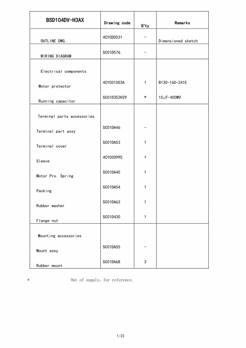
BSD104DV-H3AX
Drawing code
Q’ty
Remarks
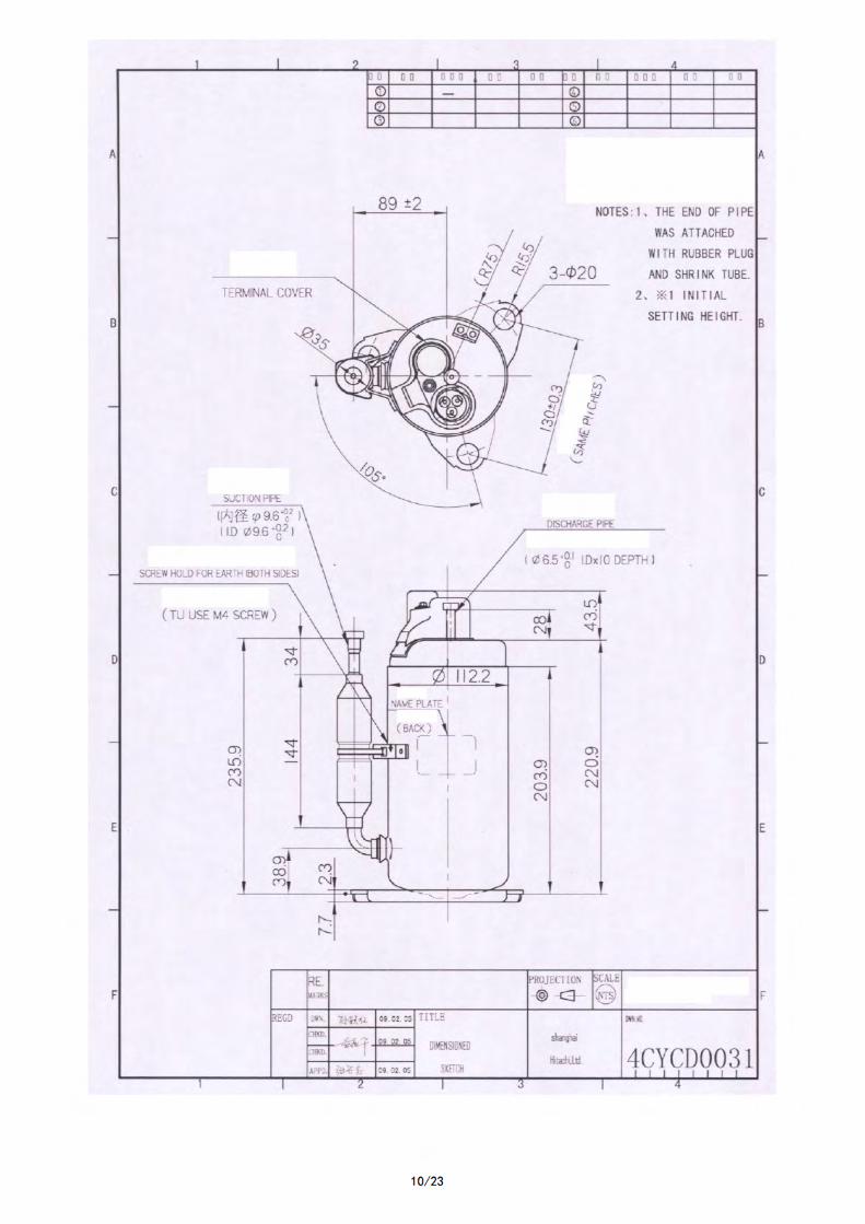
OUTLINE DWG. 4CYCD0031 -
Dimensioned sketch
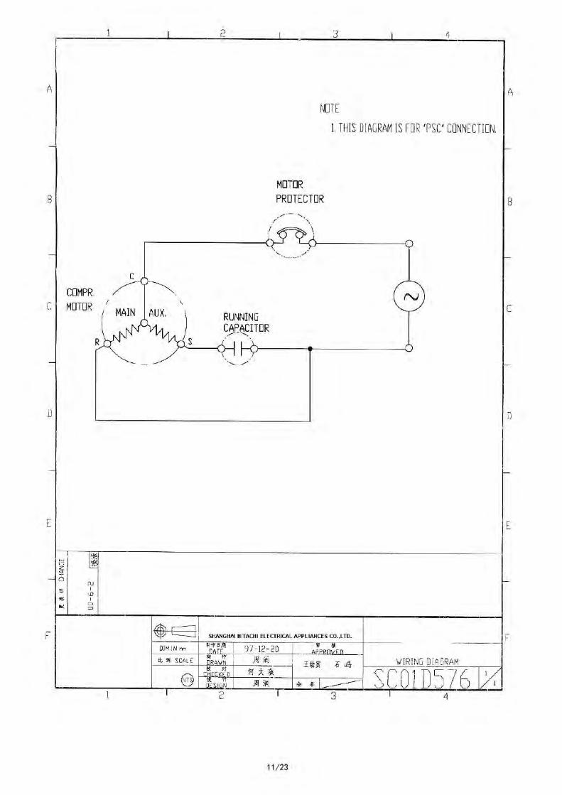
WIRING DIAGRAM SC01D576 -
Electrical components
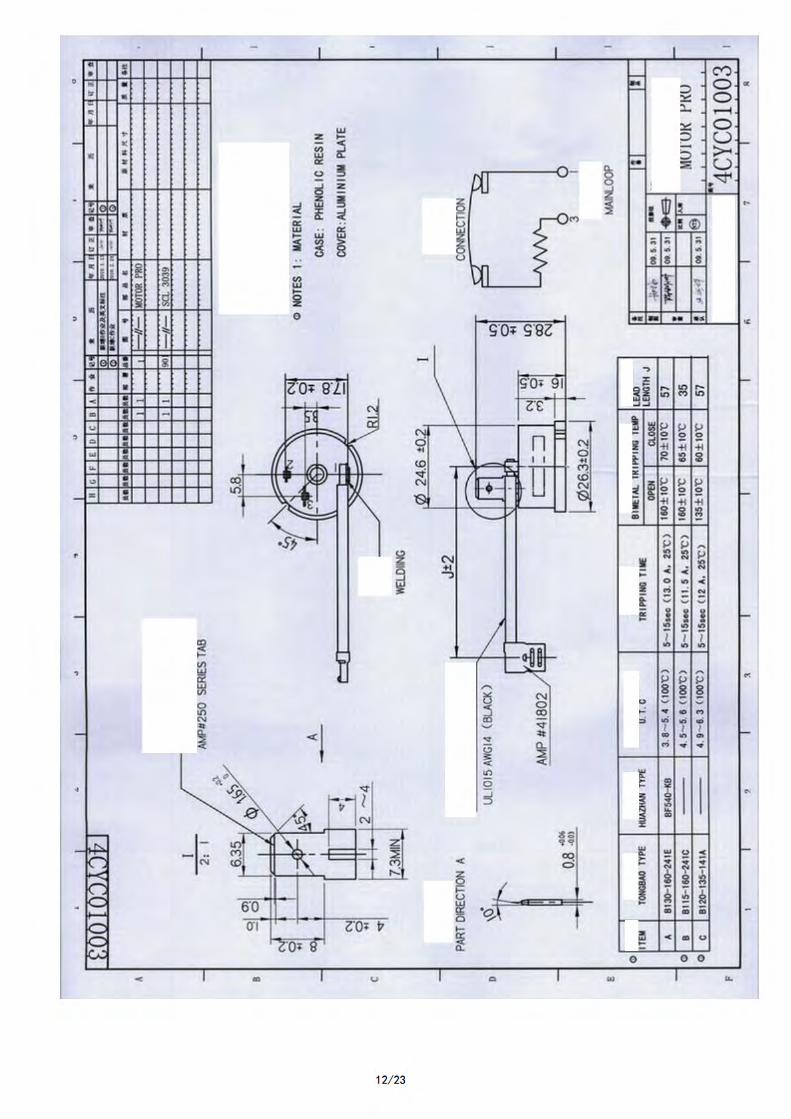
Motor protector 4CYC01003A 1 B130-160-241E
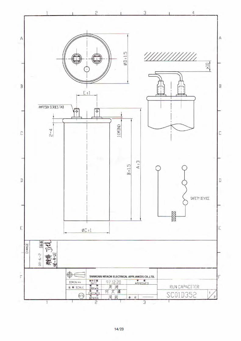
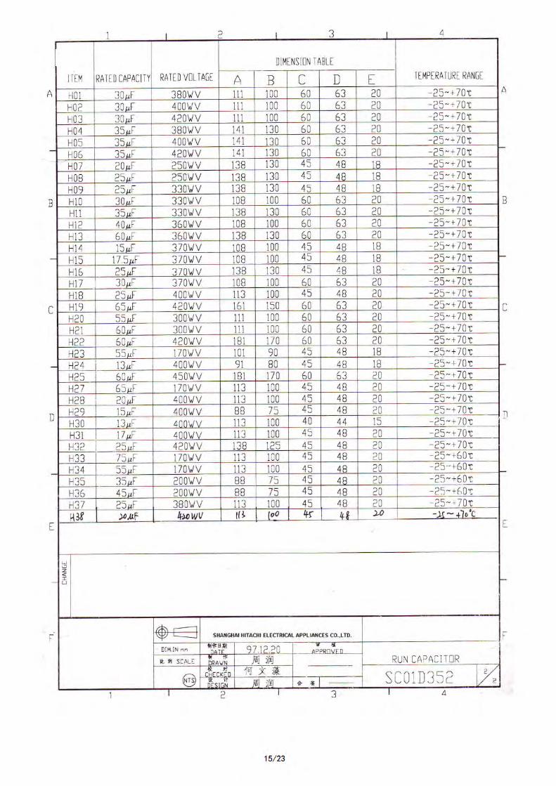
Running capacitor SC01D352H29 * 15µF-400WV
Terminal parts accessories
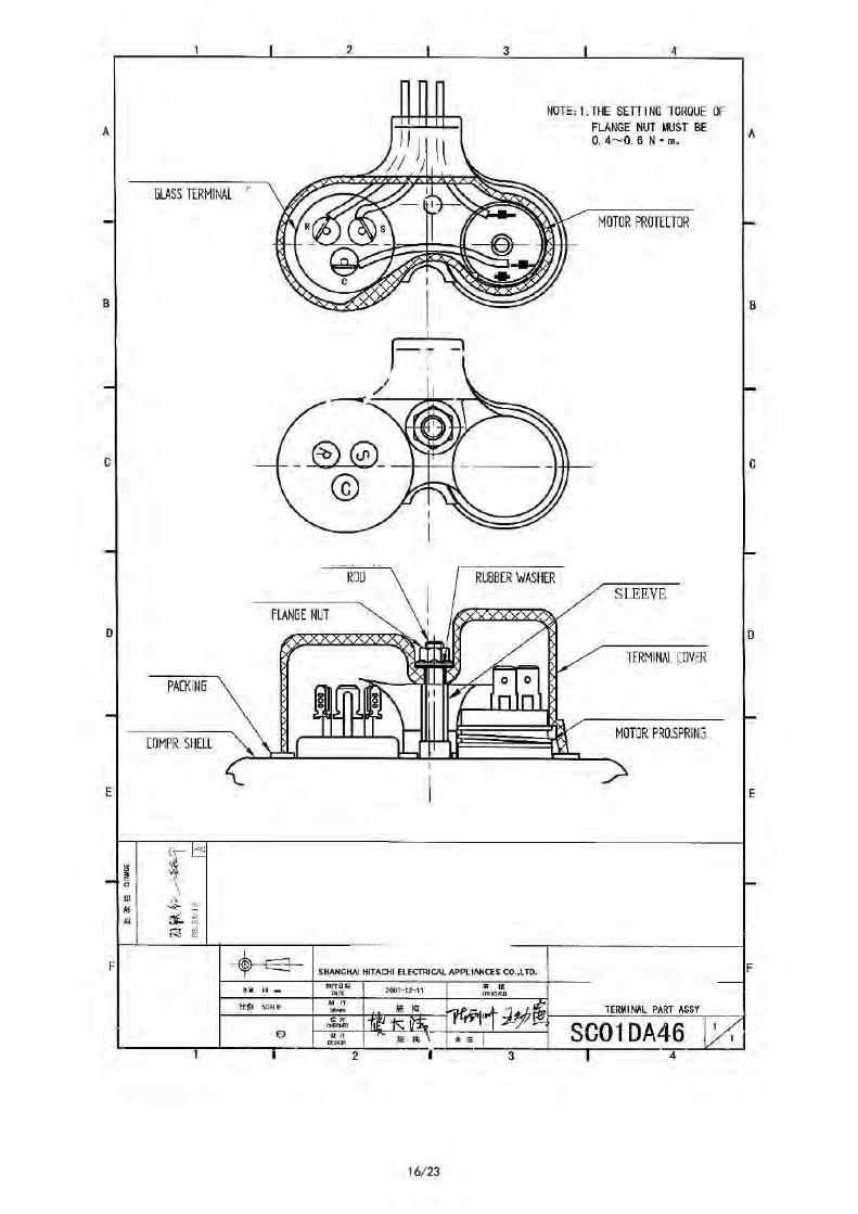
Terminal part assy SC01DA46 -
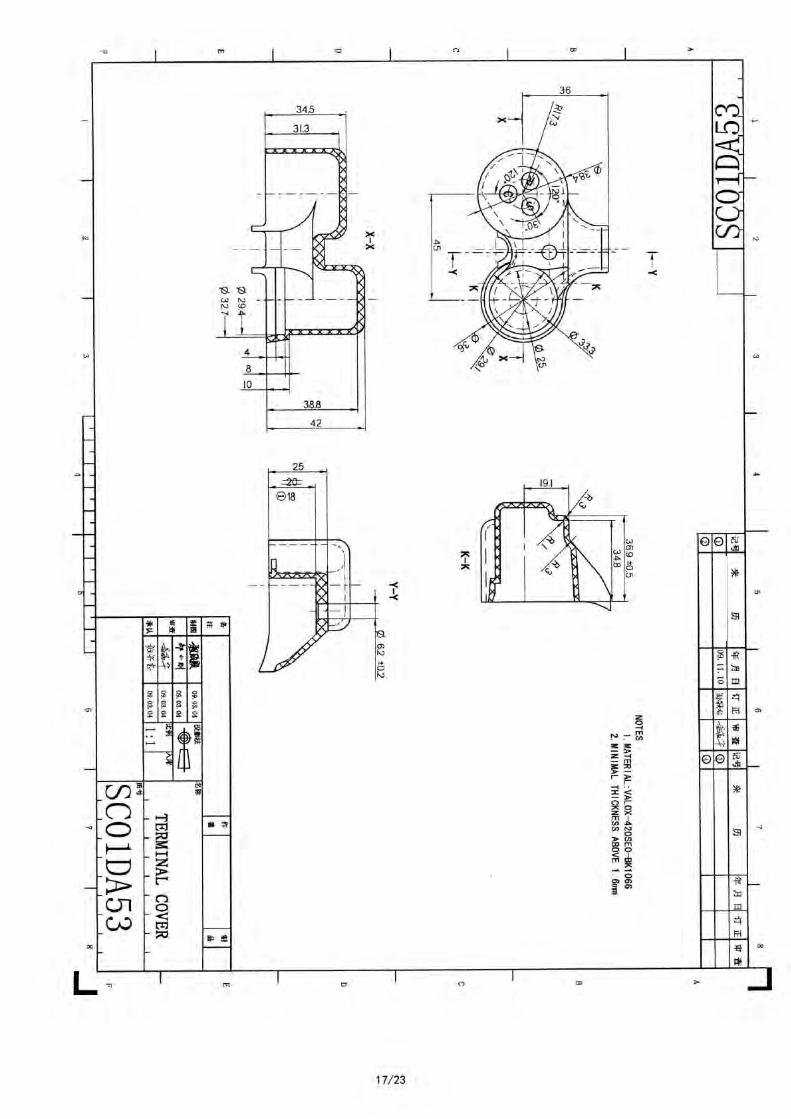
Terminal cover SC01DA53 1
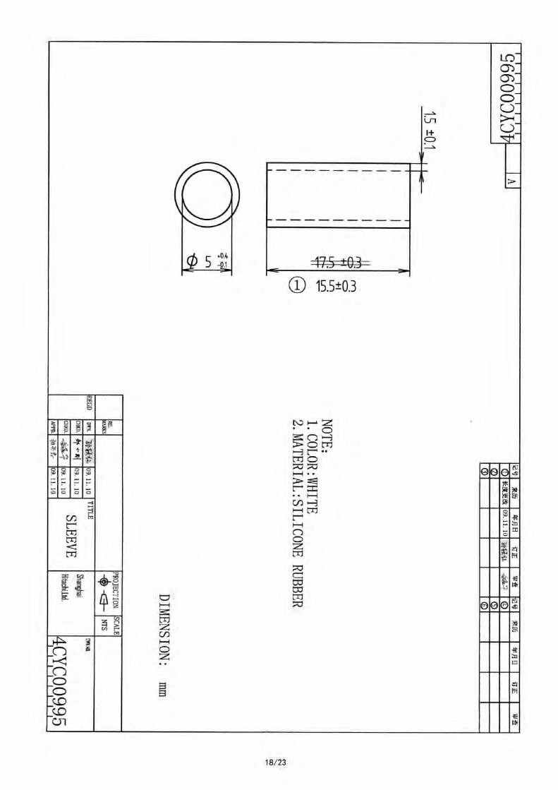
Sleeve 4CYC00995 1
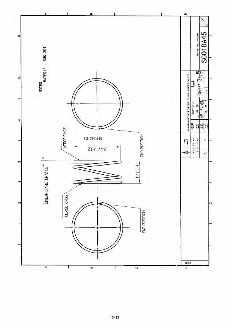
Motor Pro. Spring SC01DA45 1
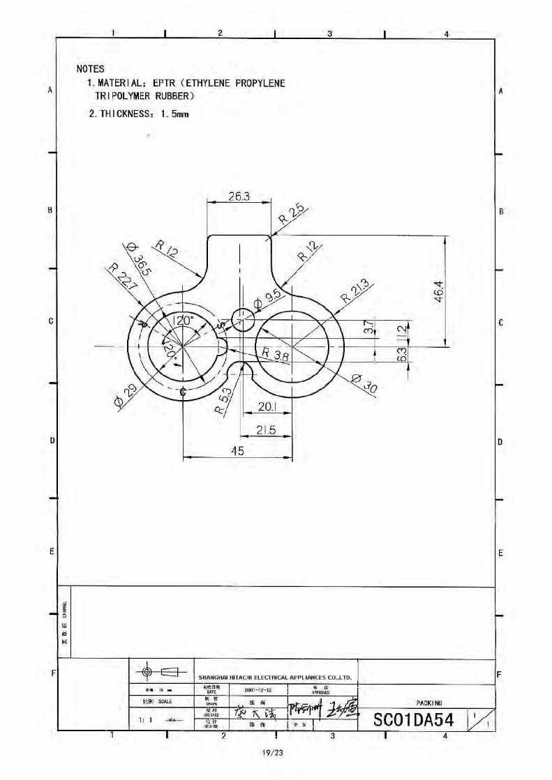
Packing SC01DA54 1
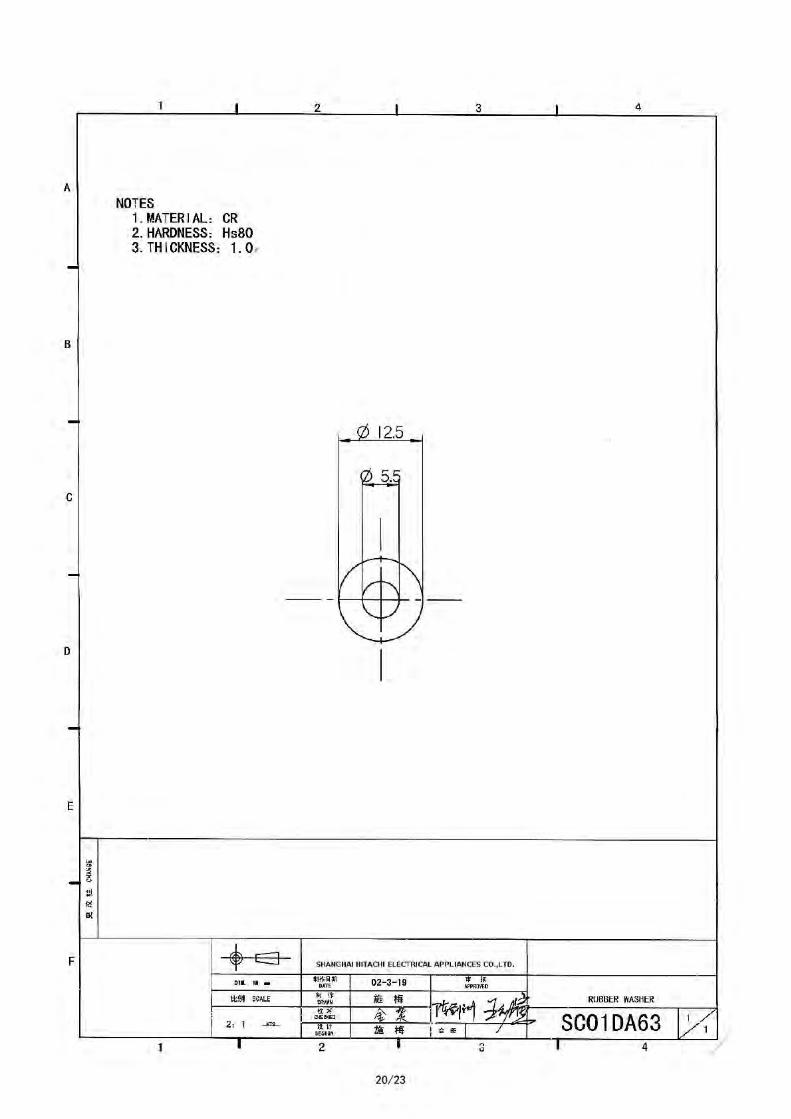
Rubber washer SC01DA63 1
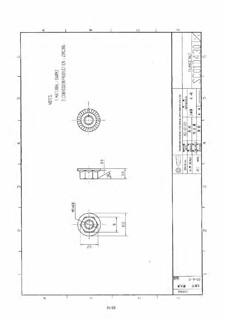
Flange nut SC01D430 1
Mounting accessories
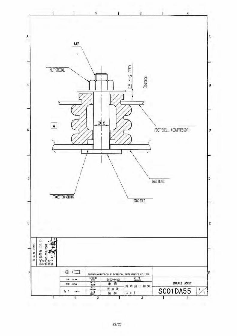
Mount assy SC01DA55 -
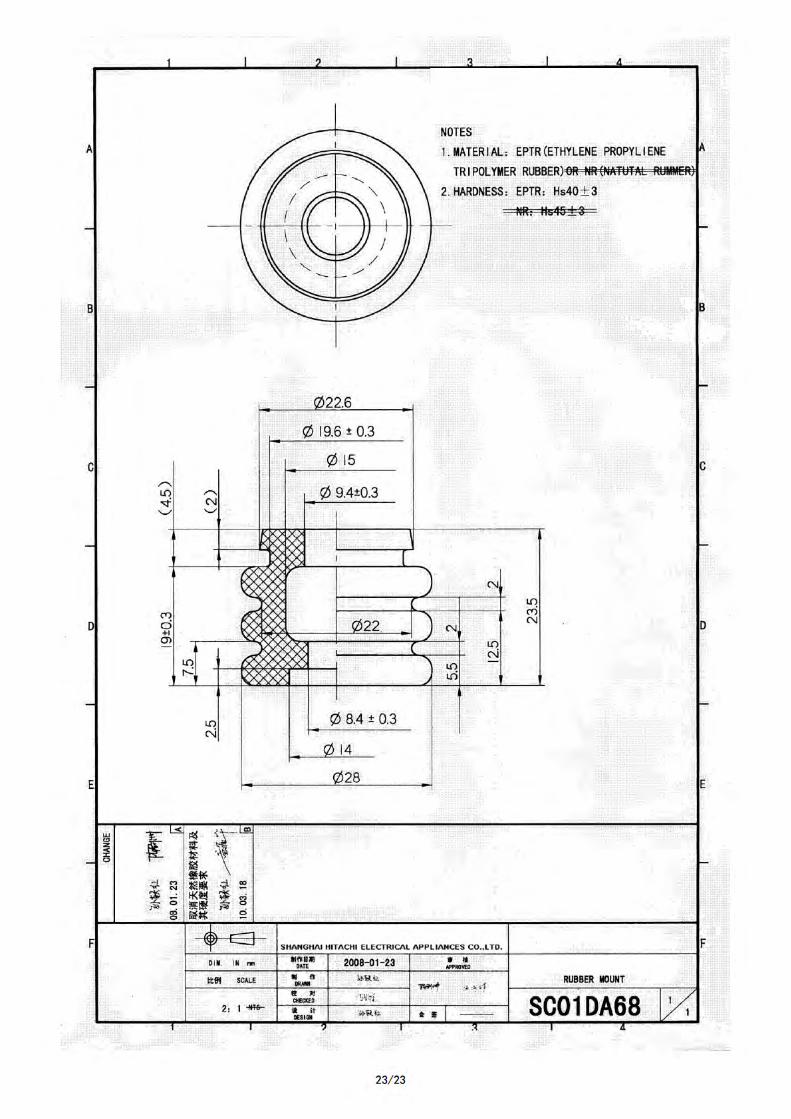
Rubber mount SC01DA68 3
* Out of supply,for reference.
2/23
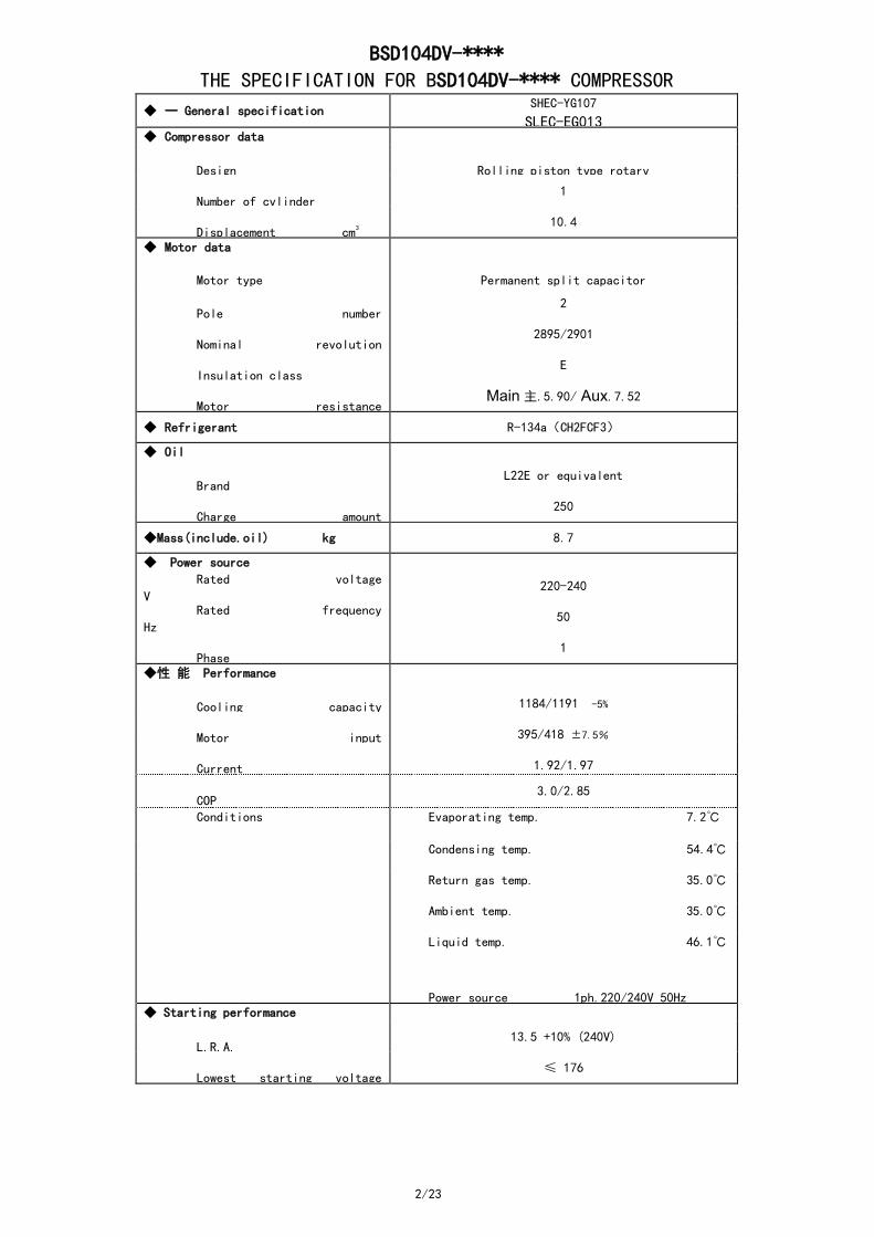
BSD104DV-****
THE SPECIFICATION FOR BSD104DV-**** COMPRESSOR
◆ 一 General specification SHEC-YG107
SLEC-EG013 ◆ Compressor data
Design
Rolling piston type rotary
Number of cylinder 1
Displacement cm3
10.4
◆ Motor data
Motor type
Permanent split capacitor
Pole number
2
Nominal revolution
2895/2901
Insulation class E
Motor resistance
Main 主.5.90/ Aux.7.52
◆ Refrigerant R-134a(CH2FCF3)
◆ Oil
Brand L22E or equivalent
Charge amount
250
◆Mass(include.oil) kg 8.7
◆ Power source
Rated voltage
V 220-240
Rated frequency
Hz 50
Phase 1
◆性 能 Performance
Cooling capacity
1184/1191 -5%
Motor input
395/418 ±7.5%
Current
1.92/1.97
COP
3.0/2.85
Conditions Evaporating temp. 7.2℃
Condensing temp. 54.4℃
Return gas temp. 35.0℃
Ambient temp. 35.0℃
Liquid temp. 46.1℃
Power source 1ph.220/240V 50Hz ◆ Starting performance
L.R.A.
13.5 +10% (240V)
Lowest starting voltage
≤ 176
6/23
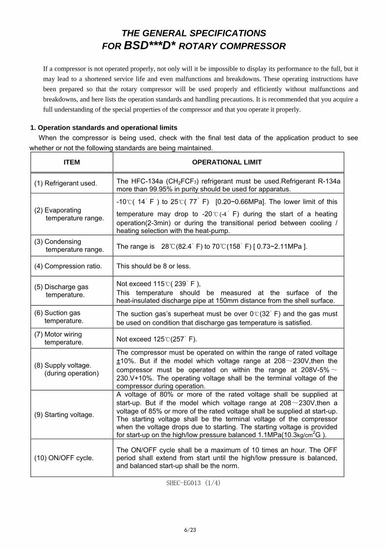
THE GENERAL SPECIFICATIONS
FOR BSD***D* ROTARY COMPRESSOR
If a compressor is not operated properly, not only will it be impossible to display its performance to the full, but it
may lead to a shortened service life and even malfunctions and breakdowns. These operating instructions have
been prepared so that the rotary compressor will be used properly and efficiently without malfunctions and
breakdowns, and here lists the operation standards and handling precautions. It is recommended that you acquire a
full understanding of the special properties of the compressor and that you operate it properly.
1. Operation standards and operational limits
When the compressor is being used, check with the final test data of the application product to see whether or not the following standards are being maintained.
ITEM OPERATIONAL LIMIT
(1) Refrigerant used. The HFC-134a (CH2FCF3) refrigerant must be used.Refrigerant R-134a more than 99.95% in purity should be used for apparatus.
(2) Evaporating temperature range.
-10℃( 14。F ) to 25℃( 77。
F) [0.20~0.66MPa]. The lower limit of this
temperature may drop to -20℃ (-4。F) during the start of a heating
operation(2-3min) or during the transitional period between cooling / heating selection with the heat-pump.
(3) Condensing temperature range. The range is 28℃(82.4。F) to 70℃(158。F) [ 0.73~2.11MPa ].
(4) Compression ratio. This should be 8 or less.
(5) Discharge gas temperature.
Not exceed 115℃( 239。F ), This temperature should be measured at the surface of the heat-insulated discharge pipe at 150mm distance from the shell surface.
(6) Suction gas temperature.
The suction gas’s superheat must be over 0℃(32。F) and the gas must be used on condition that discharge gas temperature is satisfied.
(7) Motor wiring temperature. Not exceed 125℃(257。F).
(8) Supply voltage. (during operation)
The compressor must be operated on within the range of rated voltage ±10%. But if the model which voltage range at 208~230V,then the compressor must be operated on within the range at 208V-5%~230.V+10%. The operating voltage shall be the terminal voltage of the compressor during operation.
(9) Starting voltage.
A voltage of 80% or more of the rated voltage shall be supplied at start-up. But if the model which voltage range at 208~230V,then a voltage of 85% or more of the rated voltage shall be supplied at start-up. The starting voltage shall be the terminal voltage of the compressor when the voltage drops due to starting. The starting voltage is provided for start-up on the high/low pressure balanced 1.1MPa(10.3kg/cm2G ).
(10) ON/OFF cycle. The ON/OFF cycle shall be a maximum of 10 times an hour. The OFF period shall extend from start until the high/low pressure is balanced, and balanced start-up shall be the norm.
SHEC-EG013 (1/4)
7/23
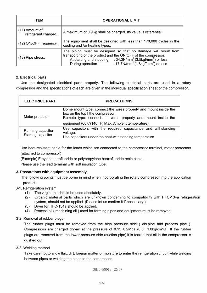
ITEM OPERATIONAL LIMIT
(11) Amount of refrigerant charged. A maximum of 0.9Kg shall be charged. Its value is referential.
(12) ON/OFF frequency. The equipment shall be designed with less than 170,000 cycles in the cooling and /or heating types.
(13) Pipe stress.
The piping must be designed so that no damage will result from transporting of the product and the ON/OFF of the compressor.
At starting and stopping : 34.3N/mm2 (3.5kgf/mm2) or less During operation : 17.7N/mm2 (1.8kgf/mm2) or less
2. Electrical parts
Use the designated electrical parts properly. The following electrical parts are used in a rotary compressor and the specifications of each are given in the individual specification sheet of the compressor.
ELECTRICL PART PRECAUTIONS
Motor protector
Dome mount type: connect the wires properly and mount inside the box on the top f the compressor. Remote type: connect the wires properly and mount inside the equipment {60℃(140。F) Max. Ambient temperature}.
Running capacitor Starting capacitor
Use capacitors with the required capacitance and withstanding voltage. Use capacitors under the heat-withstanding temperature.
Use heat-resistant cable for the leads which are connected to the compressor terminal, motor protectors (attached to compressor) (Example) Ethylene tetrafluoride or polypropylene heaxafluoride resin cable. Please use the lead terminal with soft insulation tube.
3. Precautions with equipment assembly.
The following points must be borne in mind when incorporating the rotary compressor into the application product.
3-1. Refrigeration system (1) The virgin unit should be used absolutely. (2) Organic material parts which are unknown concerning to compatibility with HFC-134a refrigeration
system, should not be applied. (Please let us confirm it if necessary.) (3) Dryer for HFC-134a should be applied. (4) Process oil ( machining oil ) used for forming pipes and equipment must be removed.
3-2. Removal of rubber plugs The rubber plugs must be removed from the high pressure side ( dis.pipe and process pipe ). Compressors are charged dry-air at the pressure of 0.15~0.2Mpa (0.5~1.0kg/cm2G). If the rubber plugs are removed from the lower pressure side (suction pipe),it is feared that oil in the compressor is gushed out.
3-3. Welding method Take care not to allow flux, dirt, foreign matter or moisture to enter the refrigeration circuit while welding between pipes or welding the pipes to the compressor.
SHEC-EG013 (2/4)
8/23
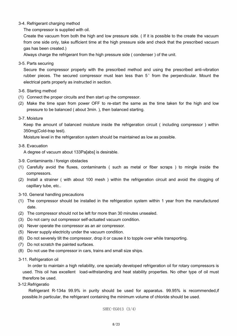
3-4. Refrigerant charging method The compressor is supplied with oil. Create the vacuum from both the high and low pressure side. ( If it is possible to the create the vacuum from one side only, take sufficient time at the high pressure side and check that the prescribed vacuum gas has been created.) Always charge the refrigerant from the high pressure side ( condenser ) of the unit.
3-5. Parts securing Secure the compressor properly with the prescribed method and using the prescribed anti-vibration rubber pieces. The secured compressor must lean less than 5°from the perpendicular. Mount the electrical parts properly as instructed in section.
3-6. Starting method (1) Connect the proper circuits and then start up the compressor. (2) Make the time span from power OFF to re-start the same as the time taken for the high and low
pressure to be balanced ( about 3min. ), then balanced starting.
3-7. Moisture Keep the amount of balanced moisture inside the refrigeration circuit ( including compressor ) within 350mg(Cold-trap test). Moisture level in the refrigeration system should be maintained as low as possible.
3-8. Evacuation A degree of vacuum about 133Pa[abs] is desirable.
3-9. Contaminants / foreign obstacles (1) Carefully avoid the fluxes, contaminants ( such as metal or fiber scraps ) to mingle inside the
compressors. (2) Install a strainer ( with about 100 mesh ) within the refrigeration circuit and avoid the clogging of
capillary tube, etc..
3-10. General handling precautions (1) The compressor should be installed in the refrigeration system within 1 year from the manufactured
date. (2) The compressor should not be left for more than 30 minutes unsealed. (3) Do not carry out compressor self-actuated vacuum condition. (4) Never operate the compressor as an air compressor. (5) Never supply electricity under the vacuum condition. (6) Do not severely tilt the compressor, drop it or cause it to topple over while transporting. (7) Do not scratch the painted surfaces. (8) Do not use the compressor in cars, trains and small size ships.
3-11. Refrigeration oil In order to maintain a high reliability, one specially developed refrigeration oil for rotary compressors is used. This oil has excellent load-withstanding and heat stability properties. No other type of oil must therefore be used.
3-12.Refrigeratio Refrigerant R-134a 99.9% in purity should be used for apparatus. 99.95% is recommended,if
possible.In particular, the refrigerant containing the minimum volume of chloride should be used.
SHEC-EG013 (3/4)
9/23
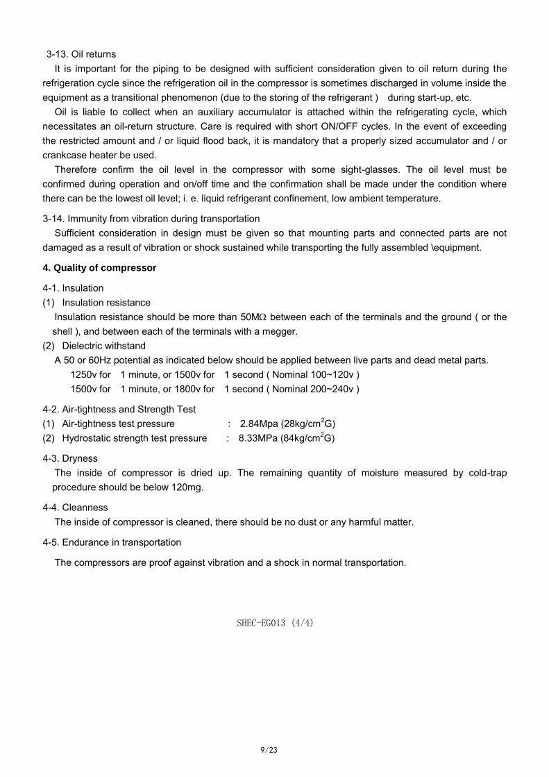
3-13. Oil returns It is important for the piping to be designed with sufficient consideration given to oil return during the
refrigeration cycle since the refrigeration oil in the compressor is sometimes discharged in volume inside the equipment as a transitional phenomenon (due to the storing of the refrigerant ) during start-up, etc.
Oil is liable to collect when an auxiliary accumulator is attached within the refrigerating cycle, which necessitates an oil-return structure. Care is required with short ON/OFF cycles. In the event of exceeding the restricted amount and / or liquid flood back, it is mandatory that a properly sized accumulator and / or crankcase heater be used.
Therefore confirm the oil level in the compressor with some sight-glasses. The oil level must be confirmed during operation and on/off time and the confirmation shall be made under the condition where there can be the lowest oil level; i. e. liquid refrigerant confinement, low ambient temperature.
3-14. Immunity from vibration during transportation Sufficient consideration in design must be given so that mounting parts and connected parts are not
damaged as a result of vibration or shock sustained while transporting the fully assembled \equipment.
4. Quality of compressor
4-1. Insulation (1) Insulation resistance
Insulation resistance should be more than 50M between each of the terminals and the ground ( or the shell ), and between each of the terminals with a megger.
(2) Dielectric withstand A 50 or 60Hz potential as indicated below should be applied between live parts and dead metal parts.
1250v for 1 minute, or 1500v for 1 second ( Nominal 100~120v ) 1500v for 1 minute, or 1800v for 1 second ( Nominal 200~240v )
4-2. Air-tightness and Strength Test (1) Air-tightness test pressure : 2.84Mpa (28kg/cm2G) (2) Hydrostatic strength test pressure : 8.33MPa (84kg/cm2G)
4-3. Dryness The inside of compressor is dried up. The remaining quantity of moisture measured by cold-trap procedure should be below 120mg.
4-4. Cleanness The inside of compressor is cleaned, there should be no dust or any harmful matter.
4-5. Endurance in transportation
The compressors are proof against vibration and a shock in normal transportation.
SHEC-EG013 (4/4)