Embed Size (px)
Citation preview
GENERAL CHARACTERISTICS | Page 1 of 67
BTL-4000 Topline Series USER‘S GUIDE
100IE20/12/2007
PAGE 2 OF 67
BEFORE YOU START
Take a moment to reflect on the advantages of the BTL-4000 Topline Electrical Stimulation, Ultrasound, Laser and Magnet technology in your own clinic. The BTL-4000 Topline system has many benefits not available in other systems. For example, the touch screen is a major step forward since it allows users to precisely monitor the therapy and document and store patient data for later recall. A choice of therapy protocols offers maximum flexibility in a variety of clinical applications.
The combination electrical stimulation / ultrasound / laser and magnet therapy system also offers substantial benefits since it eliminates the need to purchase separate units. We sincerely believe the latest BTL physiotherapy system is technically superior to any other physiotherapy products available and will provide years of trouble-free and profitable use.
All of us at BTL wish you every success with your BTL-4000 Topline system. We pride ourselves on being as responsive as possible to our customers’ needs. Your suggestions and comments are always welcome since we believe an ongoing relationship with our customers is critically important to our future product line. Please call or email us your suggestions.
While we would like you to start using your equipment right away, we encourage you to thoroughly read this manual in order to fully understand the operational features of the BTL-4000 Topline system.
Again, thank you for being a BTL customer. In the event of any problem, or if you require service, please make an initial call to your local distributor, who will decide whether to refer the problem to our office.
PAGE 3 OF 67
CONTENTS 1 GENERAL CHARACTERISTICS........................................................................................................................ 6 2 INSTRUCTIONS FOR USE ................................................................................................................................ 7 2.1 Top Panel ...................................................................................................................................................... 7 2.2 Rear Panel..................................................................................................................................................... 8 2.3 Front Panel .................................................................................................................................................... 8 2.4 Installation of Touch Pen Holder.................................................................................................................... 9 2.5 Unpacking And Assembly.............................................................................................................................. 9 2.6 Operating the Unit ....................................................................................................................................... 12 2.6.1 Touch Screen......................................................................................................................................... 12 2.6.2 Numerical Keyboard............................................................................................................................... 13 2.7 Therapy Setting ........................................................................................................................................... 14 2.7.1 Therapy Flow Chart................................................................................................................................ 14 2.7.2 Welcome Screen and Selection of Channels, Tabs and Accessories.................................................... 15 2.7.3 Setting Therapy Parameters Via Diag Option ........................................................................................ 16 2.7.4 Setting Therapy Parameters Via Prog Option ........................................................................................ 17 2.7.5 Setting Therapy Parameters Manually Via The ‘MAN' Button................................................................ 18 2.7.6 Therapy Parameters Screen – Ergonomic, Standard and Expert Mode ................................................ 19 2.8 Course of Therapy....................................................................................................................................... 20 2.8.1 Start, Interrupt and End of Therapy........................................................................................................ 20 2.8.2 Running Therapy Screen ....................................................................................................................... 21 2.8.3 Electrotherapy – Setting During Therapy ............................................................................................... 21 2.8.4 Accessories / Applicators – Visual Signalization. ................................................................................... 22 2.8.5 Indication of Operation – Energy On Operation ..................................................................................... 24 2.9 Therapy Parameters .................................................................................................................................... 26 2.10 ENCYCLOPAEDIA ...................................................................................................................................... 26 2.11 Therapy Saving ........................................................................................................................................... 27 2.11.1 Save Therapy......................................................................................................................................... 27 2.11.2 Save Therapy and Add It To The Patient Data ...................................................................................... 28 2.11.3 CopYing the Settings of The Therapy Parameters Between Tabs of the Same Type............................ 29 2.12 Interconnection of Units ............................................................................................................................... 30 2.12.1 Interconnection of BTL 4000 Topline Puls (combi) and Vacuum Unit BTL Vac ..................................... 30 2.12.2 Interconnection of BTL-4000 Topline Puls and BTL-4000 Topline Sono................................................ 30 2.12.3 Interconnection of BTL-4000 Topline Puls, BTL-4000 Topline Sono and BTL Vac................................ 31 2.12.4 Setup and Operation of Combined Therapy in INDIVIDUAL Devices .................................................... 32 2.12.5 Stopping Combined Therapy in INDIVIDUAL Devices ........................................................................... 32 3 MENU BUTTON................................................................................................................................................ 33 3.1 Accessories ................................................................................................................................................. 33 3.1.1 Installation of Accessories...................................................................................................................... 33 3.1.2 Information About Accessories .............................................................................................................. 33 3.1.3 Connectors – Information....................................................................................................................... 33 3.2 Unit Settings ................................................................................................................................................ 34 3.2.1 Password Setting ................................................................................................................................... 34 3.2.2 Sound Setting ........................................................................................................................................ 34 3.2.3 Screen Saver and Auto Switch-Off ........................................................................................................ 34 3.2.4 Setting of Colours .................................................................................................................................. 35 3.2.5 Display Options...................................................................................................................................... 35
PAGE 4 OF 67
3.2.6 Date and Time Setting ........................................................................................................................... 35 3.2.7 Language Setting................................................................................................................................... 35 3.2.8 Operation Mode ..................................................................................................................................... 35 3.2.9 Touch Panel Calibration......................................................................................................................... 35 3.2.10 User Options .......................................................................................................................................... 36 3.2.11 Style of Operation .................................................................................................................................. 36 3.2.12 Setting of HW Key.................................................................................................................................. 36 3.2.13 Unit Information...................................................................................................................................... 36 3.2.13 Unlock Code .......................................................................................................................................... 36 3.2.14 Service Functions .................................................................................................................................. 36 3.3 Special Settings........................................................................................................................................... 37 4 USER SETTINGS OPTION............................................................................................................................... 38 4.1 Clients.......................................................................................................................................................... 38 4.2 User Sequences .......................................................................................................................................... 39 4.2.1 Creating New Sequence ........................................................................................................................ 39 4.2.2 Parameters of Sections in Sequence..................................................................................................... 41 4.2.3 Saving New Sequence........................................................................................................................... 41 4.3 User Diagnoses / Programs......................................................................................................................... 42 4.4 List of Recent Therapies.............................................................................................................................. 42 5 ACCESSORIES ................................................................................................................................................ 43 5.1 Power Supply Adapter 60W / Adapter 90W................................................................................................. 43 5.2 Accumulator................................................................................................................................................. 43 5.3 Lithium Battery............................................................................................................................................. 44 5.4 Accessories Common for All Units .............................................................................................................. 44 5.5 Accessories for Electrotherapy .................................................................................................................... 44 5.6 Accessories for Ultrasound Therapy............................................................................................................ 45 5.7 Accessories for Laser Therapy .................................................................................................................... 45 5.8 Accessories for Magnetotherapy ................................................................................................................. 45 6 MAINTENANCE AND SAFETY INSTRUCTIONS ............................................................................................ 46 6.1 Safety .......................................................................................................................................................... 47 6.2 Contraindications......................................................................................................................................... 51 6.2.1 Contraindications for Electrotherapy ...................................................................................................... 51 6.2.2 Contraindications for Ultrasound............................................................................................................ 52 6.2.3 Contraindications for Laser Therapy ...................................................................................................... 52 6.2.4 Contraindications for Magnetotherapy ................................................................................................... 53 6.3 Useful Addresses......................................................................................................................................... 53 6.4 Warranty ...................................................................................................................................................... 53 7 TECHNICAL PARAMETERS ........................................................................................................................... 54 7.1 Technical Parameters of The BTL-4000 Topline Series Devices ................................................................ 54 7.2 Technical Parameters of Power Supply Adapter 60W / Adapter 90W ......................................................... 55 7.3 Basic Parameters of Electrotherapy Generator ........................................................................................... 56 7.4 Basic Parameters of Ultrasound Generator ................................................................................................. 56 7.5 Basic Parameters of Laser Generator ......................................................................................................... 57 7.6 Basic parameters of Magnet Generator....................................................................................................... 57 7.7 Technical Parameters of Ultrasound Heads ................................................................................................ 58 7.8 Technical Parameters of Laser Probes........................................................................................................ 58 7.9 Technical Parameters of Laser Clusters...................................................................................................... 59 7.10 Technical parameters of Magnetic Applicators ............................................................................................ 60 7.11 Applicable Standards................................................................................................................................... 60 7.12 Interconnection of Devices .......................................................................................................................... 61

PAGE 5 OF 67
7.13 Manufacturer ............................................................................................................................................... 61 8 UNITS CONFIGURATIONS.............................................................................................................................. 62 8.1 Table of Configurations of the Combined Devices BTL 4000 Topline Series .............................................. 62 8.2 Table of Configurations of the Electrotherapy Devices BTL-4000 Topline Puls........................................... 65 8.3 Table of Configurations of the Ultrasound Therapy Devices BTL-4000 Topline Sono................................. 66 8.4 Table of Configurations of the Laser Therapy Devices BTL-4000 Topline Laser......................................... 66 8.5 Table of Configurations of the Magnetotherapy Devices BTL-4000 Topline Magnet................................... 67
GENERAL CHARACTERISTICS | Page 6 of 67
1 GENERAL CHARACTERISTICS
The BTL-4000 Topline Series offers advanced and well designed physiotherapy units for professional use. Depending on the required configuration, each system can consist of up to four units - for electrotherapy, ultrasound, laser or magnet therapy treatment.
The touch-controlled display considerably simplifies the use of the unit. The touch screen is equipped with a touch stylus for more convenient operation. The vertically positioned case of the instrument enables you to see the information on the screen clearly and from different positions. In addition, the display's brightness can be adjusted to fit the light conditions in the office. The information displayed on the screen will guide you throughout the whole therapy. Simply adjust the parameters by pressing the touch screen buttons and turn the main knob to set the intensity.
The modular design of the BTL equipment allows you to build the combination you require. Combine an electrotherapy unit of your choice with either ultrasound, laser or magnet all in a single unit. This can save considerable money in your physiotherapy investment
Selecting a diagnosis from a list of alphabetically organized treatment protocols, or selecting a program, will make an easy and efficient start of the therapy. Naturally, you can adjust any treatment parameter manually by the simple use of the touch screen buttons. Throughout the whole therapy, the display informs you about the remaining therapy time, channel and therapeutic method used, the type of therapy applied, attached accessories, and other necessary data.
If several accessories are attached to your unit at the same time, you can easily recognize the accessory required for a specific treatment. Select a treatment on the display (electrotherapy, ultrasound, laser or magnet), and the control light on the corresponding accessory (electrotherapy cable, ultrasound head, laser probe / cluster or magnet disc / double disc / linear or solenoid applicator) will start blinking to indicate that this accessory should be used.
Save time by using the pre-programming of the BTL-4000 Topline units. Based on detailed research and practical use of the units, the well-organized pre-programmed protocols will give you recommendations for treating various conditions. The unit also includes up to 500 free lots to define your own protocols. Moreover, you can recall the last 20 treatments.
Add the names of your patients and other relevant information to the unit's internal memory and connect the patient data with pre-programmed or your own protocols. When your patients call again, simply recall their name and apply the pre-set therapy.
With every BTL unit, you can purchase a cart specially designed for BTL products. Its versatile design allows you to conveniently store and use 1 or 2 physiotherapy units and a vacuum unit. The cart includes a range of accessory trays and baskets. Four well-built and steady castors ensure easy movement of the unit in the office or hospital.
Please visit our corporate website at http://www.btlnet.com for the latest information on BTL products and services.
INSTRUCTIONS FOR USE | PAGE 7 OF 67
2 INSTRUCTIONS FOR USE
2.1 TOP PANEL
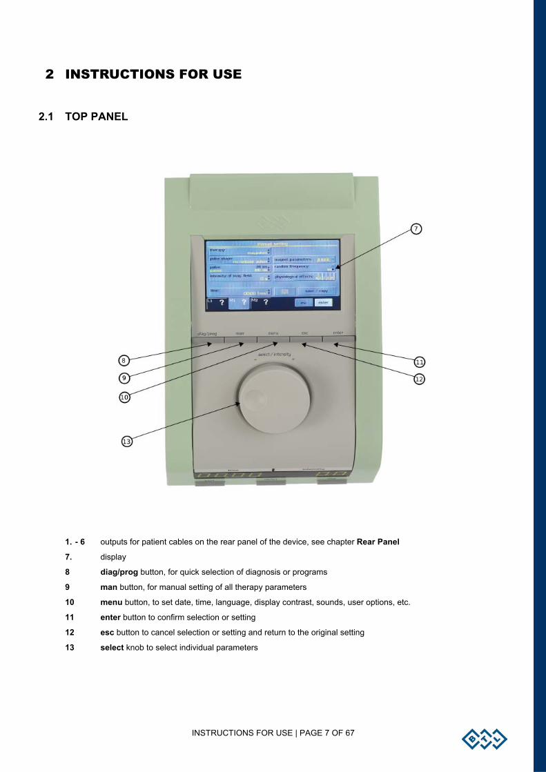
1. - 6 outputs for patient cables on the rear panel of the device, see chapter Rear Panel
7. display
8 diag/prog button, for quick selection of diagnosis or programs
9 man button, for manual setting of all therapy parameters
10 menu button, to set date, time, language, display contrast, sounds, user options, etc.
11 enter button to confirm selection or setting
12 esc button to cancel selection or setting and return to the original setting
13 select knob to select individual parameters
INSTRUCTIONS FOR USE | PAGE 8 OF 67
2.2 REAR PANEL
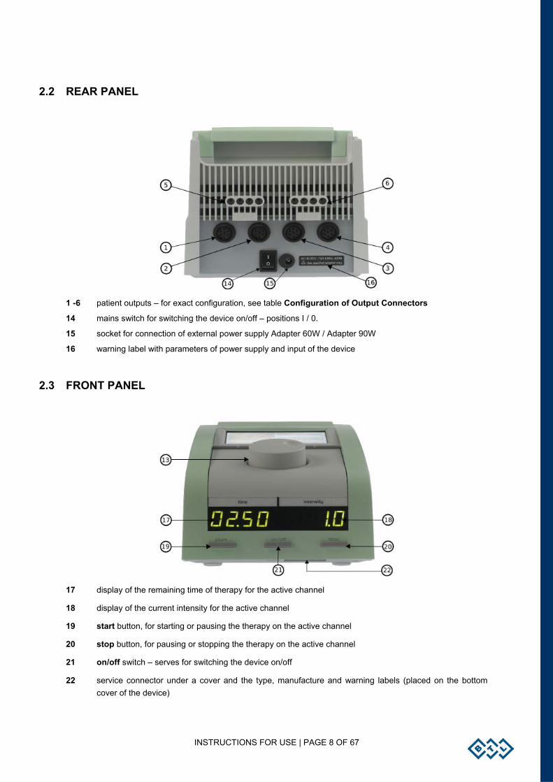
1 -6 patient outputs – for exact configuration, see table Configuration of Output Connectors
14 mains switch for switching the device on/off – positions I / 0.
15 socket for connection of external power supply Adapter 60W / Adapter 90W
16 warning label with parameters of power supply and input of the device
2.3 FRONT PANEL
17 display of the remaining time of therapy for the active channel
18 display of the current intensity for the active channel
19 start button, for starting or pausing the therapy on the active channel
20 stop button, for pausing or stopping the therapy on the active channel
21 on/off switch – serves for switching the device on/off
22 service connector under a cover and the type, manufacture and warning labels (placed on the bottom cover of the device)
INSTRUCTIONS FOR USE | PAGE 9 OF 67
2.4 INSTALLATION OF TOUCH PEN HOLDER
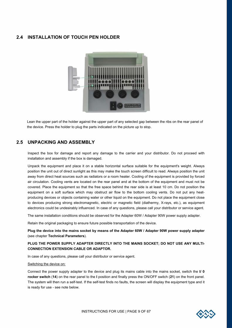
Lean the upper part of the holder against the upper part of any selected gap between the ribs on the rear panel of the device. Press the holder to plug the parts indicated on the picture up to stop.
2.5 UNPACKING AND ASSEMBLY
Inspect the box for damage and report any damage to the carrier and your distributor. Do not proceed with installation and assembly if the box is damaged.
Unpack the equipment and place it on a stable horizontal surface suitable for the equipment's weight. Always position the unit out of direct sunlight as this may make the touch screen difficult to read. Always position the unit away from direct heat sources such as radiators or a room heater. Cooling of the equipment is provided by forced air circulation. Cooling vents are located on the rear panel and at the bottom of the equipment and must not be covered. Place the equipment so that the free space behind the rear side is at least 10 cm. Do not position the equipment on a soft surface which may obstruct air flow to the bottom cooling vents. Do not put any heat-producing devices or objects containing water or other liquid on the equipment. Do not place the equipment close to devices producing strong electromagnetic, electric or magnetic field (diathermy, X-rays, etc.), as equipment electronics could be undesirably influenced. In case of any questions, please call your distributor or service agent.
The same installation conditions should be observed for the Adapter 60W / Adapter 90W power supply adapter.
Retain the original packaging to ensure future possible transportation of the device.
Plug the device into the mains socket by means of the Adapter 60W / Adapter 90W power supply adapter (see chapter Technical Parameters).
PLUG THE POWER SUPPLY ADAPTER DIRECTLY INTO THE MAINS SOCKET; DO NOT USE ANY MULTI-CONNECTION EXTENSION CABLE OR ADAPTOR.
In case of any questions, please call your distributor or service agent.
Switching the device on:
Connect the power supply adapter to the device and plug its mains cable into the mains socket, switch the I/ 0 rocker switch (14) on the rear panel to the I position and finally press the ON/OFF switch (21) on the front panel. The system will then run a self-test. If the self-test finds no faults, the screen will display the equipment type and it is ready for use - see note below.

INSTRUCTIONS FOR USE | PAGE 10 OF 67
Connection of accessories
Connect the accessories to the output connectors (1) - (6) on the rear panel in this way:
Put in the cable connector and secure the fluted ring by pressing and turning in clockwise. ATTENTION WHEN DISCONNECTING THE CONNECTOR, first of all, it is necessary to take by the fingers the fluted ring NOT THE WHOLE connector. TURN THE FLUTED RING ANTICLOCKWISE and then after releasing the ring, disconnect the connector by pulling the fluted ring still held in the fingers!
ATTENTION!!! DO NOT TURN THE WHOLE CONNECTOR USING FORCE, THE DEVICE COULD BE DAMAGED.
For configuration of the output connectors (1) to (6), see the table Configuration of Output Connectors
The unit will automatically detect the accessories type and display it on the screen. If a wrong one is connected, the equipment will not operate and the screen will display a warning and help about where to connect which accessory.
Recharging the accumulator
The device accumulator is sold in half-charged status. That is why we recommend formatting the accumulator after purchase of the device: connect the device to the mains via the external adapter for at least 48 hours without interruption, with the mains rocker switch (14) in position I. The device will be recharged and the accumulator will be properly formatted. A properly formatted accumulator enables longer operation of the device without mains supply. For details, see the chapter Accumulator.
Restart of the device - reset
If for any reason (electromagnetic interference, etc.) the device stops responding to the user's commands and the message "please wait..." with small moving squares is not displayed, the device can be put into the initial state by simultaneously pressing the man (9) and enter (11) buttons. After this, the device immediately goes into the initial status.
Note:
After switching on, the unit tests for about 10 - 15 secs all internal functions. If any fault exists, the screen will display a warning. If any fault that compromises patient safety exists, the system will 'lock' itself into ‘secure’ mode. If this situation occurs, please call your local distributor for service advice.
INSTRUCTIONS FOR USE | PAGE 11 OF 67
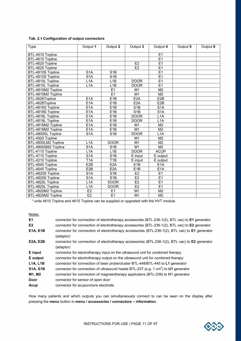
Tab. 2.1 Configuration of output connectors
Type Output 1 Output 2 Output 3 Output 4 Output 5 Output 6
BTL-4610 Topline E1 BTL-4615 Topline E1 BTL-4620 Topline E2 E1 BTL-4625 Topline E2 E1 BTL-4810S Topline S1A S1B E1 BTL-4815S Topline S1A S1B E1 BTL-4810L Topline L1A L1B DOOR E1 BTL-4815L Topline L1A L1B DOOR E1 BTL-4810M2 Topline E1 M1 M2 BTL-4815M2 Topline E1 M1 M2 BTL-4626Topline E1A E1B E2A E2B BTL-4628Topline E1A E1B E2A E2B BTL-4816S Topline E1A E1B S1B S1A BTL-4818S Topline E1A E1B S1B S1A BTL-4816L Topline E1A E1B DOOR L1A BTL-4818L Topline E1A E1B DOOR L1A BTL-4816M2 Topline E1A E1B M1 M2 BTL-4818M2 Topline E1A E1B M1 M2 BTL-4800SL Topline S1A S1B DOOR L1A BTL-4920 Topline M1 M2 BTL-4800LM2 Topline L1A DOOR M1 M2 BTL-4800SM2 Topline S1A S1B M1 M2 BTL-4110 Topline L1A L1B DOOR ACUP BTL-4710 Topline S1A S1B E input E output BTL-4210 Topline T1A T1B E input E output BTL-4640 Topline E2B E2A E1B E1A BTL-4645 Topline E2B E2A E1B E1A BTL-4820S Topline S1A S1B E2 E1 BTL-4825S Topline S1A S1B E2 E1 BTL-4820L Topline L1A DOOR E2 E1 BTL-4825L Topline L1A DOOR E2 E1 BTL-4820M2 Topline E2 E1 M1 M2 BTL-4825M2 Topline E2 E1 M1 M2
* units 4610 Topline and 4615 Topline can be supplied or upgraded with the HVT module
Notes: E1 connector for connection of electrotherapy accessories (BTL-236-1(2), BTL vac) to E1 generator E2 connector for connection of electrotherapy accessories (BTL-236-1(2), BTL vac) to E2 generator E1A, E1B connector for connection of electrotherapy accessories (BTL-236-1(2), BTL vac) to E1 generator (adaptor) E2A, E2B connector for connection of electrotherapy accessories (BTL-236-1(2), BTL vac) to E2 generator (adaptor) E input connector for electrotherapy input on the ultrasound unit for combined therapy E output connector for electrotherapy output on the ultrasound unit for combined therapy L1A, L1B connector for connection of laser probe/cluster BTL-448/BTL-445 to L1 generator S1A, S1B connector for connection of ultrasound heads BTL-237 (e.g. 1 cm2) to U1 generator M1, M2 connector for connection of magnetotherapy applicators (BTL-239) to M1 generator Door connector for sensor of open door Acup connector for acupuncture electrode How many patients and which outputs you can simultaneously connect to can be seen on the display after pressing the menu button in menu / accessories / connectors – information.
INSTRUCTIONS FOR USE | PAGE 12 OF 67
2.6 OPERATING THE UNIT
2.6.1 TOUCH SCREEN
The touch screen may be operated by finger touch or using the special soft tip stylus that is supplied with the unit. DO NOT TOUCH THE SCREEN WITH A SHARP OBJECT OR PEN, AS THIS MAY CAUSE PERMANENT DAMAGE.
Select required parameters by pressing:
1. 3D buttons.
2. Bright tabs of the selected channel (in the lower left corner of the screen) to switch between connected accessories, such as ultrasound heads or laser accessories.
3. The dark tab of the required channel (in the lower left corner of the screen) to switch between channels.
Touch screen buttons:
The touch screen buttons have three dimensional (3D) shading and may be pressed with the finger or special stylus. To confirm the requested changes or values, press enter. To cancel the changes, press escape (esc).
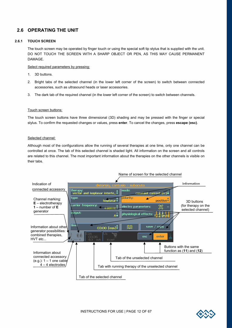
Selected channel:
Although most of the configurations allow the running of several therapies at one time, only one channel can be controlled at once. The tab of this selected channel is shaded light. All information on the screen and all controls are related to this channel. The most important information about the therapies on the other channels is visible on their tabs.
Name of screen for the selected channel
Information
3D buttons (for therapy on the selected channel)
Buttons with the same function as (11) and (12)
Tab of the unselected channel
Tab with running therapy of the unselected channel
Tab of the selected channel
Indication of connected accessory
Channel marking: E – electrotherapy 1 – number of E generator
Information about other generator possibilities: combined therapies, HVT etc...
Information about connected accessory: (e.g.): 1 – 1 one cable 4 – 4 electrodes
INSTRUCTIONS FOR USE | PAGE 13 OF 67
2.6.2 NUMERICAL KEYBOARD
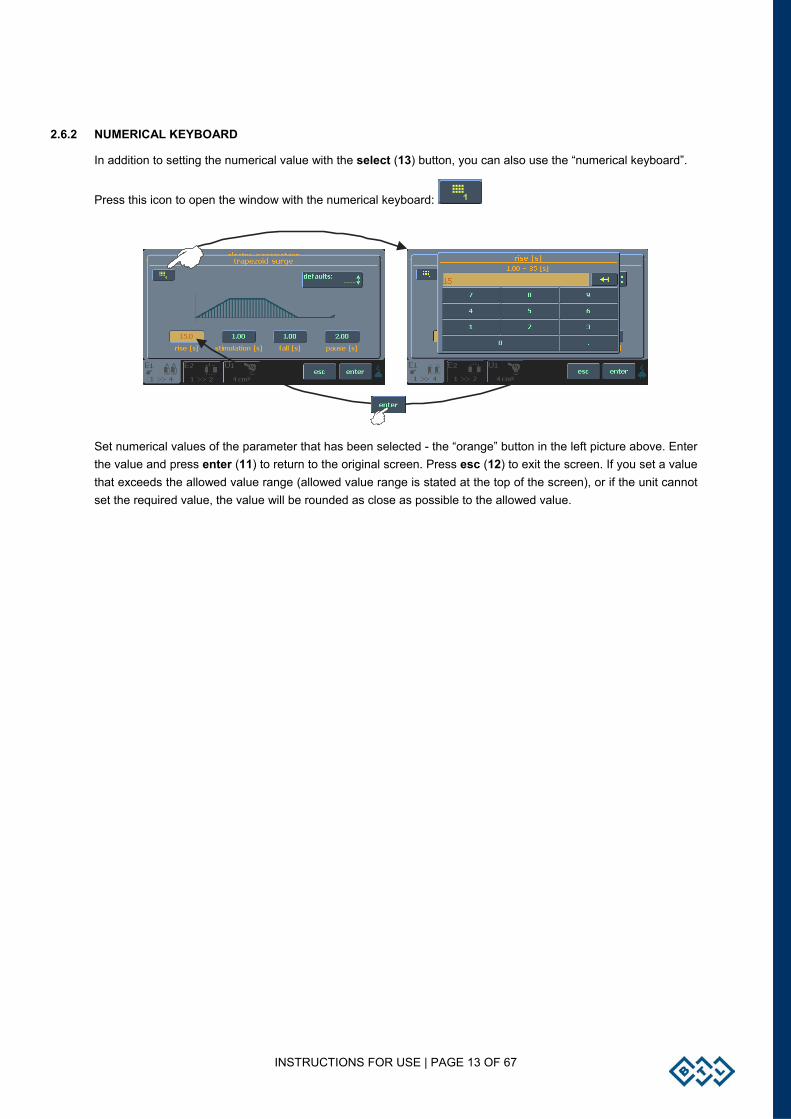
In addition to setting the numerical value with the select (13) button, you can also use the “numerical keyboard”.
Press this icon to open the window with the numerical keyboard:
Set numerical values of the parameter that has been selected - the “orange” button in the left picture above. Enter the value and press enter (11) to return to the original screen. Press esc (12) to exit the screen. If you set a value that exceeds the allowed value range (allowed value range is stated at the top of the screen), or if the unit cannot set the required value, the value will be rounded as close as possible to the allowed value.
INSTRUCTIONS FOR USE | PAGE 14 OF 67
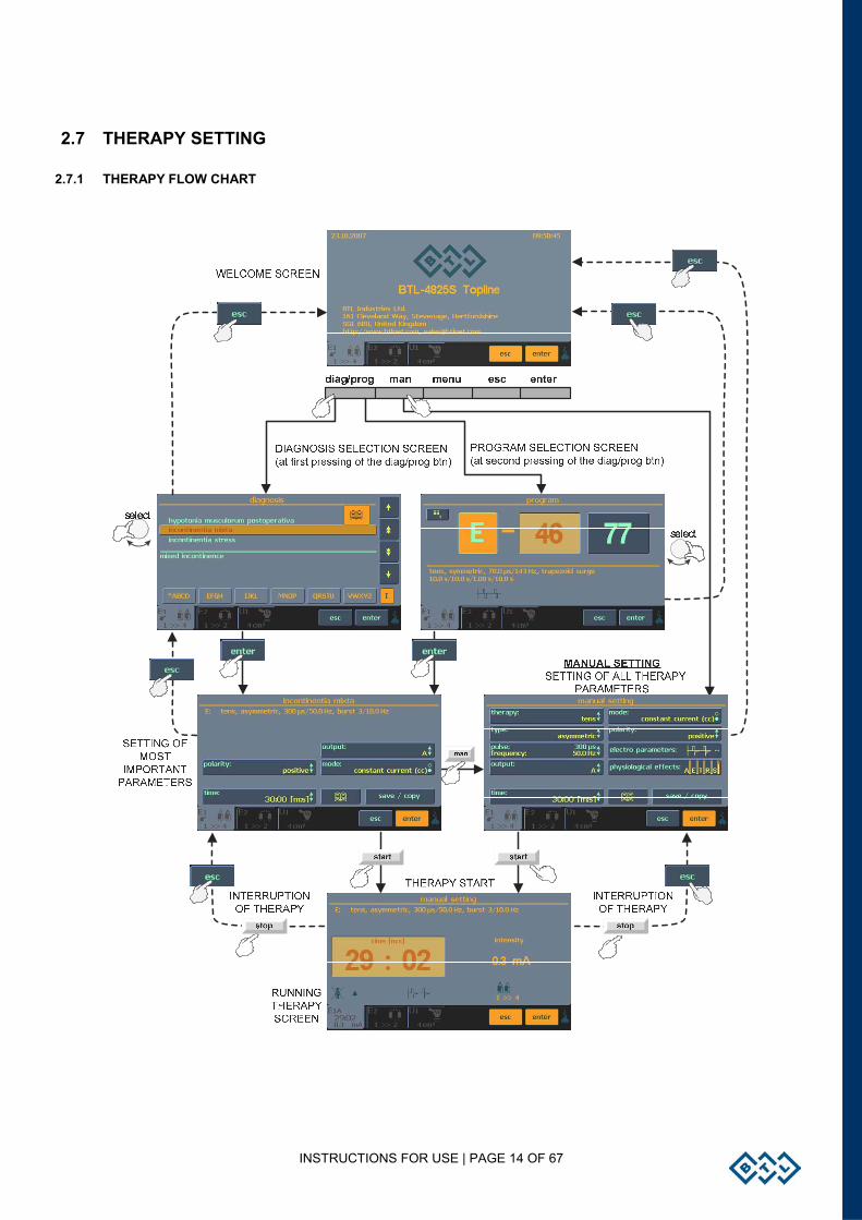
2.7 THERAPY SETTING
2.7.1 THERAPY FLOW CHART
INSTRUCTIONS FOR USE | PAGE 15 OF 67
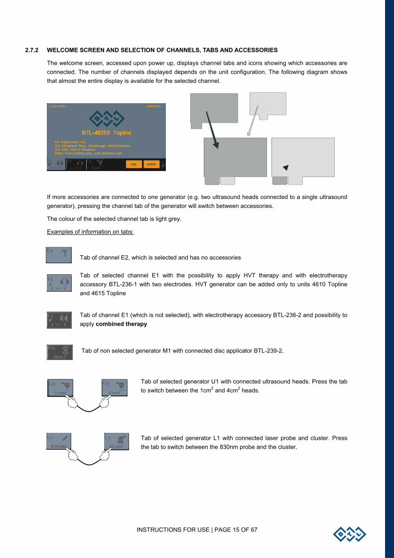
2.7.2 WELCOME SCREEN AND SELECTION OF CHANNELS, TABS AND ACCESSORIES
The welcome screen, accessed upon power up, displays channel tabs and icons showing which accessories are connected. The number of channels displayed depends on the unit configuration. The following diagram shows that almost the entire display is available for the selected channel.
If more accessories are connected to one generator (e.g. two ultrasound heads connected to a single ultrasound generator), pressing the channel tab of the generator will switch between accessories.
The colour of the selected channel tab is light grey.
Examples of information on tabs:
Tab of channel E2, which is selected and has no accessories Tab of selected channel E1 with the possibility to apply HVT therapy and with electrotherapy accessory BTL-236-1 with two electrodes. HVT generator can be added only to units 4610 Topline and 4615 Topline
Tab of channel E1 (which is not selected), with electrotherapy accessory BTL-236-2 and possibility to apply combined therapy Tab of non selected generator M1 with connected disc applicator BTL-239-2.
Tab of selected generator U1 with connected ultrasound heads. Press the tab to switch between the 1cm2 and 4cm2 heads.
Tab of selected generator L1 with connected laser probe and cluster. Press the tab to switch between the 830nm probe and the cluster.
INSTRUCTIONS FOR USE | PAGE 16 OF 67
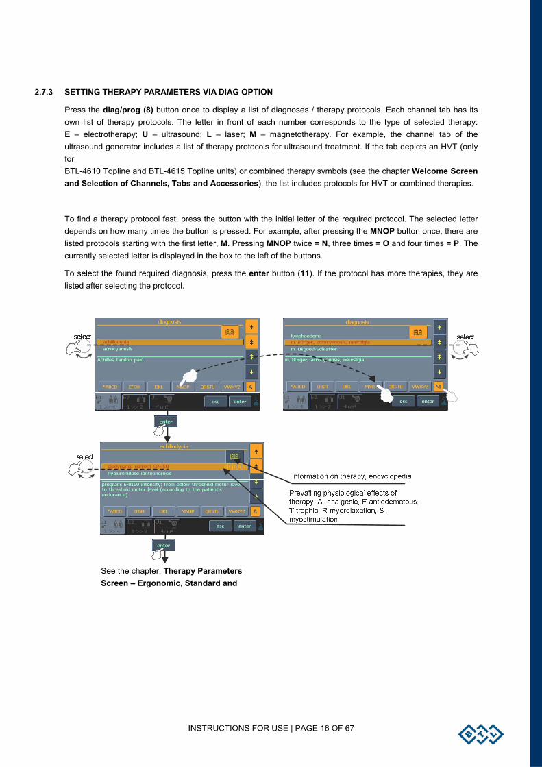
2.7.3 SETTING THERAPY PARAMETERS VIA DIAG OPTION
Press the diag/prog (8) button once to display a list of diagnoses / therapy protocols. Each channel tab has its own list of therapy protocols. The letter in front of each number corresponds to the type of selected therapy: E – electrotherapy; U – ultrasound; L – laser; M – magnetotherapy. For example, the channel tab of the ultrasound generator includes a list of therapy protocols for ultrasound treatment. If the tab depicts an HVT (only for BTL-4610 Topline and BTL-4615 Topline units) or combined therapy symbols (see the chapter Welcome Screen and Selection of Channels, Tabs and Accessories), the list includes protocols for HVT or combined therapies.
To find a therapy protocol fast, press the button with the initial letter of the required protocol. The selected letter depends on how many times the button is pressed. For example, after pressing the MNOP button once, there are listed protocols starting with the first letter, M. Pressing MNOP twice = N, three times = O and four times = P. The currently selected letter is displayed in the box to the left of the buttons.
To select the found required diagnosis, press the enter button (11). If the protocol has more therapies, they are listed after selecting the protocol.
See the chapter: Therapy Parameters Screen – Ergonomic, Standard and
INSTRUCTIONS FOR USE | PAGE 17 OF 67
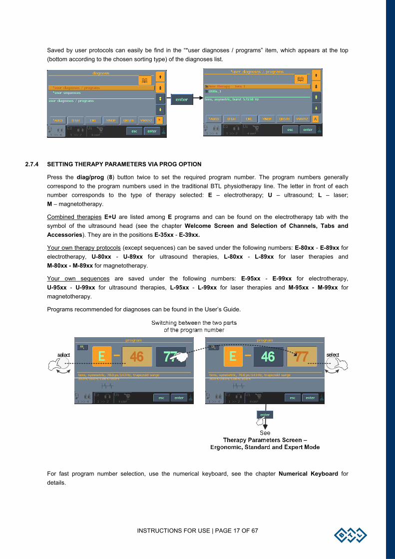
Saved by user protocols can easily be find in the “*user diagnoses / programs” item, which appears at the top (bottom according to the chosen sorting type) of the diagnoses list.
2.7.4 SETTING THERAPY PARAMETERS VIA PROG OPTION
Press the diag/prog (8) button twice to set the required program number. The program numbers generally correspond to the program numbers used in the traditional BTL physiotherapy line. The letter in front of each number corresponds to the type of therapy selected: E – electrotherapy; U – ultrasound; L – laser; M – magnetotherapy.
Combined therapies E+U are listed among E programs and can be found on the electrotherapy tab with the symbol of the ultrasound head (see the chapter Welcome Screen and Selection of Channels, Tabs and Accessories). They are in the positions E-35xx - E-39xx.
Your own therapy protocols (except sequences) can be saved under the following numbers: E-80xx - E-89xx for electrotherapy, U-80xx - U-89xx for ultrasound therapies, L-80xx - L-89xx for laser therapies and M-80xx - M-89xx for magnetotherapy.
Your own sequences are saved under the following numbers: E-95xx - E-99xx for electrotherapy, U-95xx - U-99xx for ultrasound therapies, L-95xx - L-99xx for laser therapies and M-95xx - M-99xx for magnetotherapy.
Programs recommended for diagnoses can be found in the User’s Guide.
For fast program number selection, use the numerical keyboard, see the chapter Numerical Keyboard for details.
INSTRUCTIONS FOR USE | PAGE 18 OF 67
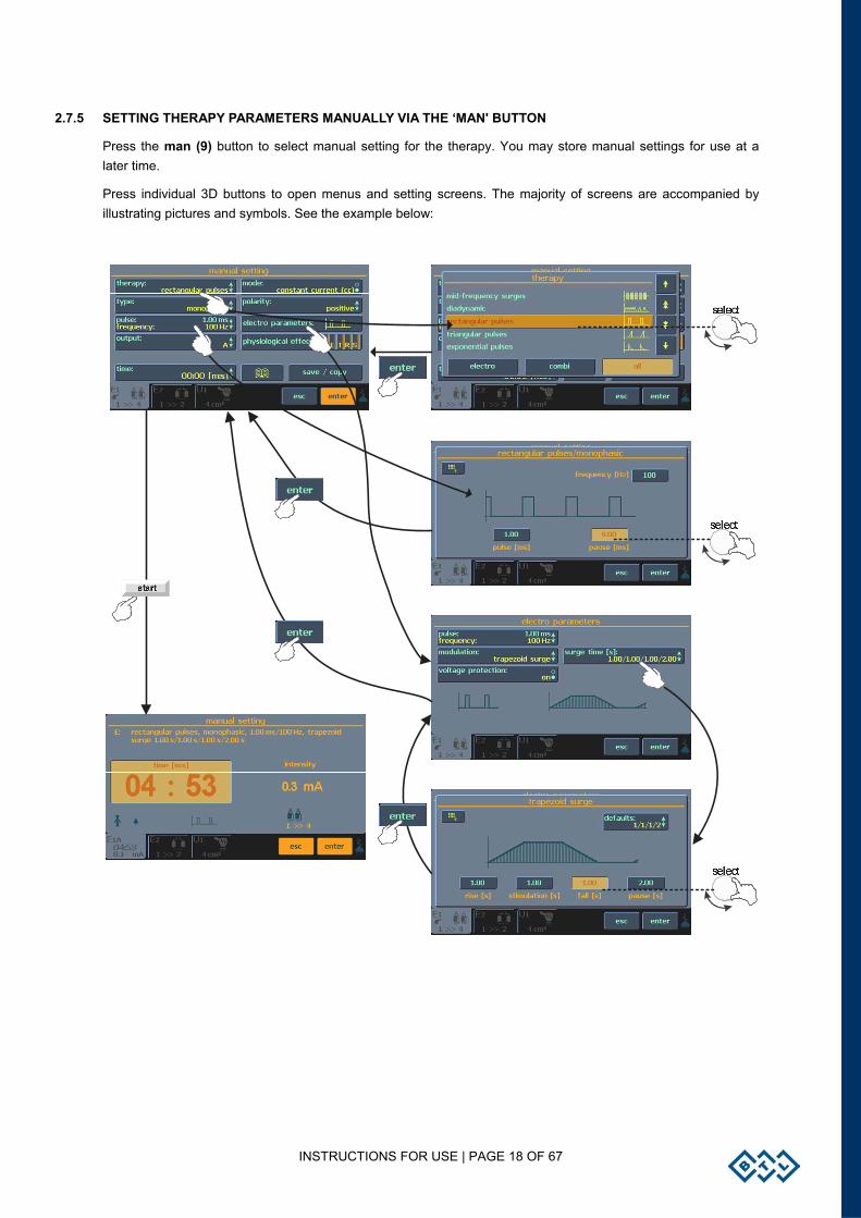
2.7.5 SETTING THERAPY PARAMETERS MANUALLY VIA THE ‘MAN' BUTTON
Press the man (9) button to select manual setting for the therapy. You may store manual settings for use at a later time.
Press individual 3D buttons to open menus and setting screens. The majority of screens are accompanied by illustrating pictures and symbols. See the example below:
INSTRUCTIONS FOR USE | PAGE 19 OF 67
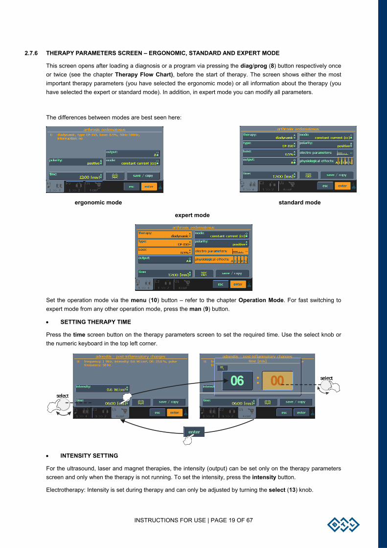
2.7.6 THERAPY PARAMETERS SCREEN – ERGONOMIC, STANDARD AND EXPERT MODE
This screen opens after loading a diagnosis or a program via pressing the diag/prog (8) button respectively once or twice (see the chapter Therapy Flow Chart), before the start of therapy. The screen shows either the most important therapy parameters (you have selected the ergonomic mode) or all information about the therapy (you have selected the expert or standard mode). In addition, in expert mode you can modify all parameters.
The differences between modes are best seen here:
ergonomic mode standard mode
expert mode
Set the operation mode via the menu (10) button – refer to the chapter Operation Mode. For fast switching to expert mode from any other operation mode, press the man (9) button.
• SETTING THERAPY TIME
Press the time screen button on the therapy parameters screen to set the required time. Use the select knob or the numeric keyboard in the top left corner.
• INTENSITY SETTING
For the ultrasound, laser and magnet therapies, the intensity (output) can be set only on the therapy parameters screen and only when the therapy is not running. To set the intensity, press the intensity button.
Electrotherapy: Intensity is set during therapy and can only be adjusted by turning the select (13) knob.
INSTRUCTIONS FOR USE | PAGE 20 OF 67
START / STOP
2.8 COURSE OF THERAPY
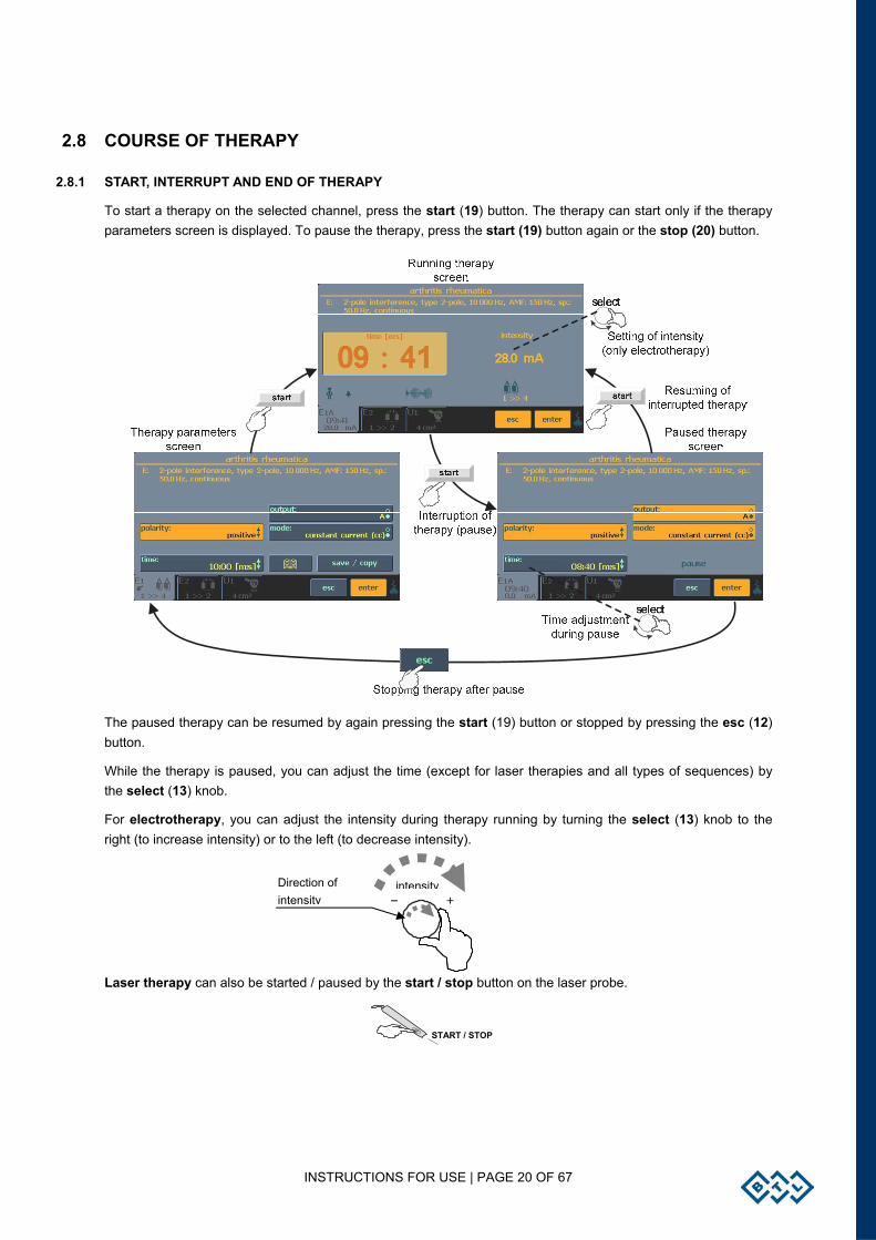
2.8.1 START, INTERRUPT AND END OF THERAPY
To start a therapy on the selected channel, press the start (19) button. The therapy can start only if the therapy parameters screen is displayed. To pause the therapy, press the start (19) button again or the stop (20) button.
The paused therapy can be resumed by again pressing the start (19) button or stopped by pressing the esc (12) button.
While the therapy is paused, you can adjust the time (except for laser therapies and all types of sequences) by the select (13) knob.
For electrotherapy, you can adjust the intensity during therapy running by turning the select (13) knob to the right (to increase intensity) or to the left (to decrease intensity).
Laser therapy can also be started / paused by the start / stop button on the laser probe.
intensityDirection of intensity
INSTRUCTIONS FOR USE | PAGE 21 OF 67
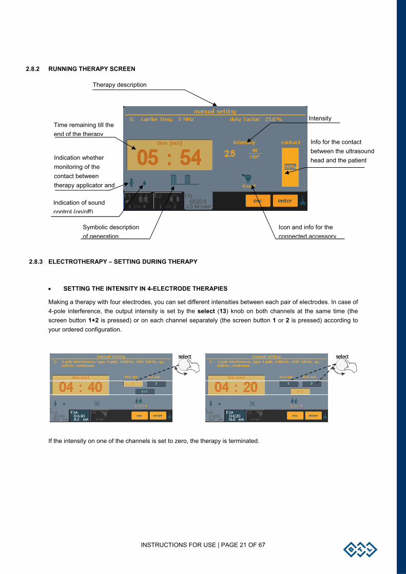
2.8.2 RUNNING THERAPY SCREEN
2.8.3 ELECTROTHERAPY – SETTING DURING THERAPY
• SETTING THE INTENSITY IN 4-ELECTRODE THERAPIES
Making a therapy with four electrodes, you can set different intensities between each pair of electrodes. In case of 4-pole interference, the output intensity is set by the select (13) knob on both channels at the same time (the screen button 1+2 is pressed) or on each channel separately (the screen button 1 or 2 is pressed) according to your ordered configuration.
If the intensity on one of the channels is set to zero, the therapy is terminated.
Therapy description
Indication whether monitoring of the contact between therapy applicator and
Intensity
Indication of sound control (on/off)
Time remaining till the end of the therapy
Symbolic description of generation
Icon and info for the connected accessory
Info for the contact between the ultrasound head and the patient
INSTRUCTIONS FOR USE | PAGE 22 OF 67
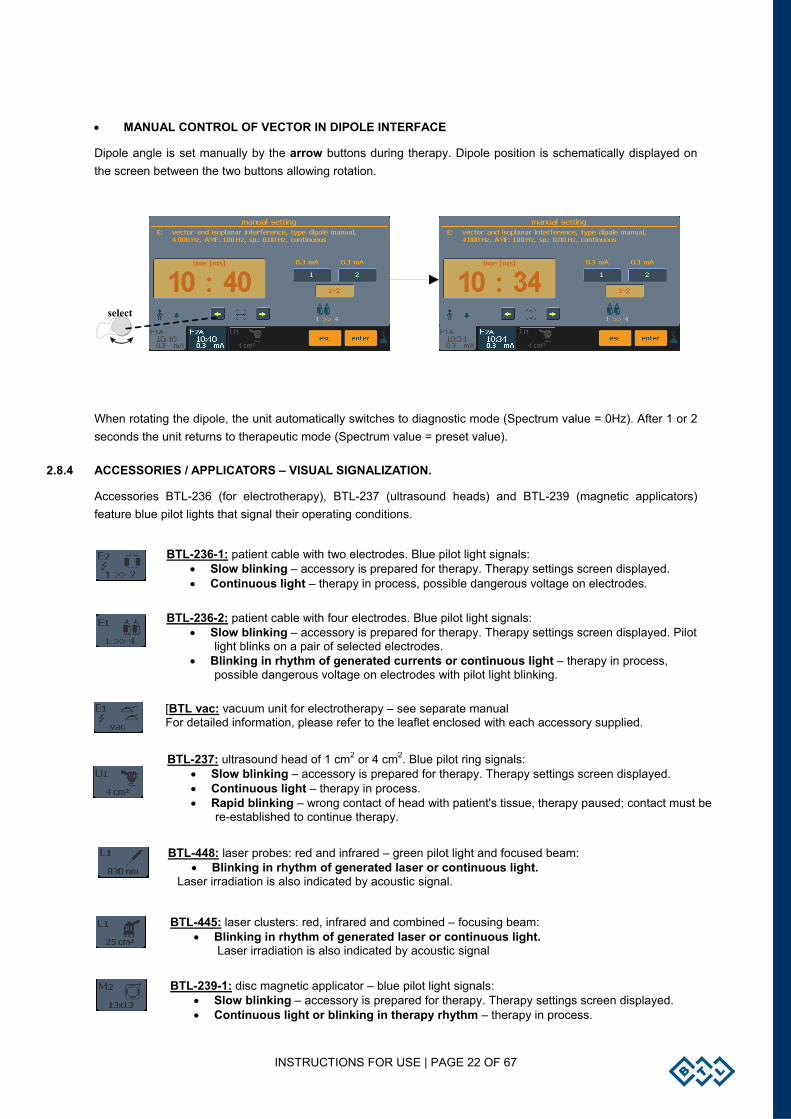
• MANUAL CONTROL OF VECTOR IN DIPOLE INTERFACE
Dipole angle is set manually by the arrow buttons during therapy. Dipole position is schematically displayed on the screen between the two buttons allowing rotation.
When rotating the dipole, the unit automatically switches to diagnostic mode (Spectrum value = 0Hz). After 1 or 2 seconds the unit returns to therapeutic mode (Spectrum value = preset value).
2.8.4 ACCESSORIES / APPLICATORS – VISUAL SIGNALIZATION.
Accessories BTL-236 (for electrotherapy), BTL-237 (ultrasound heads) and BTL-239 (magnetic applicators) feature blue pilot lights that signal their operating conditions.
select
BTL-236-1: patient cable with two electrodes. Blue pilot light signals: • Slow blinking – accessory is prepared for therapy. Therapy settings screen displayed. • Continuous light – therapy in process, possible dangerous voltage on electrodes.
BTL-236-2: patient cable with four electrodes. Blue pilot light signals: • Slow blinking – accessory is prepared for therapy. Therapy settings screen displayed. Pilot
light blinks on a pair of selected electrodes. • Blinking in rhythm of generated currents or continuous light – therapy in process,
possible dangerous voltage on electrodes with pilot light blinking.
[BTL vac: vacuum unit for electrotherapy – see separate manualFor detailed information, please refer to the leaflet enclosed with each accessory supplied.
BTL-237: ultrasound head of 1 cm2 or 4 cm2. Blue pilot ring signals: • Slow blinking – accessory is prepared for therapy. Therapy settings screen displayed. • Continuous light – therapy in process. • Rapid blinking – wrong contact of head with patient's tissue, therapy paused; contact must be
re-established to continue therapy.
BTL-448: laser probes: red and infrared – green pilot light and focused beam: • Blinking in rhythm of generated laser or continuous light.
Laser irradiation is also indicated by acoustic signal.
BTL-445: laser clusters: red, infrared and combined – focusing beam: • Blinking in rhythm of generated laser or continuous light.
Laser irradiation is also indicated by acoustic signal
BTL-239-1: disc magnetic applicator – blue pilot light signals: • Slow blinking – accessory is prepared for therapy. Therapy settings screen displayed. • Continuous light or blinking in therapy rhythm – therapy in process.
INSTRUCTIONS FOR USE | PAGE 23 OF 67
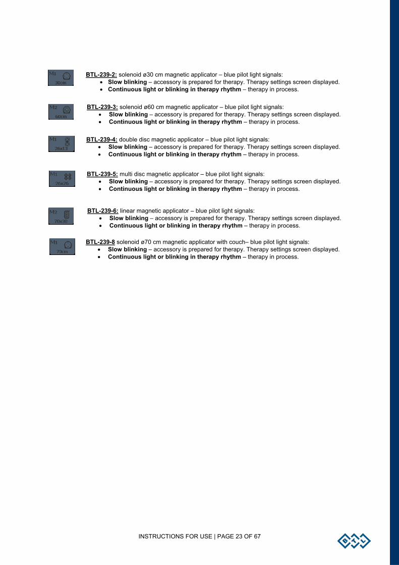
BTL-239-4: double disc magnetic applicator – blue pilot light signals: • Slow blinking – accessory is prepared for therapy. Therapy settings screen displayed. • Continuous light or blinking in therapy rhythm – therapy in process.
BTL-239-2: solenoid ø30 cm magnetic applicator – blue pilot light signals: • Slow blinking – accessory is prepared for therapy. Therapy settings screen displayed. • Continuous light or blinking in therapy rhythm – therapy in process.
BTL-239-3: solenoid ø60 cm magnetic applicator – blue pilot light signals: • Slow blinking – accessory is prepared for therapy. Therapy settings screen displayed. • Continuous light or blinking in therapy rhythm – therapy in process.
BTL-239-5: multi disc magnetic applicator – blue pilot light signals: • Slow blinking – accessory is prepared for therapy. Therapy settings screen displayed.• Continuous light or blinking in therapy rhythm – therapy in process.
BTL-239-6: linear magnetic applicator – blue pilot light signals: • Slow blinking – accessory is prepared for therapy. Therapy settings screen displayed. • Continuous light or blinking in therapy rhythm – therapy in process.
BTL-239-8 solenoid ø70 cm magnetic applicator with couch– blue pilot light signals: • Slow blinking – accessory is prepared for therapy. Therapy settings screen displayed. • Continuous light or blinking in therapy rhythm – therapy in process.
INSTRUCTIONS FOR USE | PAGE 24 OF 67
2.8.5 INDICATION OF OPERATION – ENERGY ON OPERATION
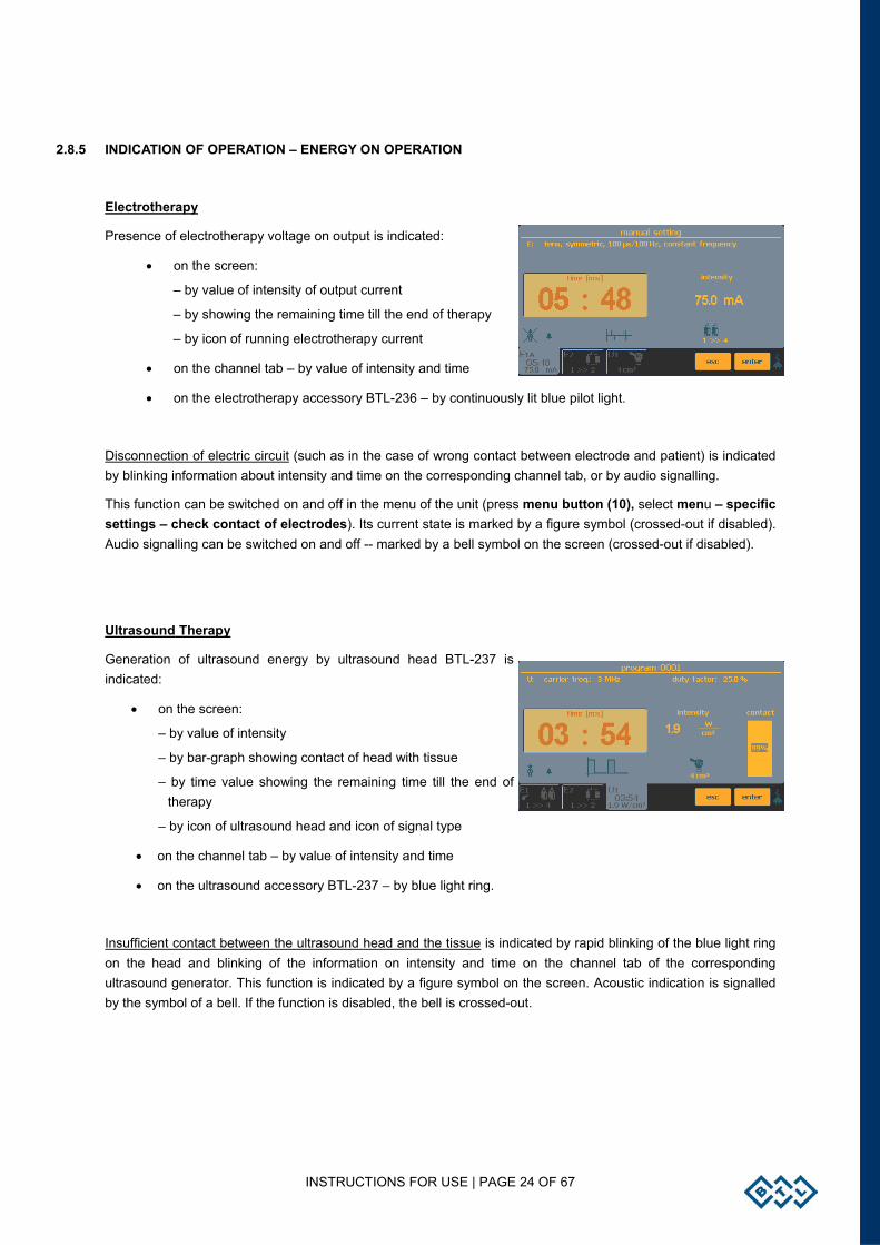
Electrotherapy
Presence of electrotherapy voltage on output is indicated:
• on the screen:
– by value of intensity of output current
– by showing the remaining time till the end of therapy
– by icon of running electrotherapy current
• on the channel tab – by value of intensity and time
• on the electrotherapy accessory BTL-236 – by continuously lit blue pilot light.
Disconnection of electric circuit (such as in the case of wrong contact between electrode and patient) is indicated by blinking information about intensity and time on the corresponding channel tab, or by audio signalling.
This function can be switched on and off in the menu of the unit (press menu button (10), select menu – specific settings – check contact of electrodes). Its current state is marked by a figure symbol (crossed-out if disabled). Audio signalling can be switched on and off -- marked by a bell symbol on the screen (crossed-out if disabled).
Ultrasound Therapy
Generation of ultrasound energy by ultrasound head BTL-237 is indicated:
• on the screen:
– by value of intensity
– by bar-graph showing contact of head with tissue
– by time value showing the remaining time till the end of therapy
– by icon of ultrasound head and icon of signal type
• on the channel tab – by value of intensity and time
• on the ultrasound accessory BTL-237 – by blue light ring.
Insufficient contact between the ultrasound head and the tissue is indicated by rapid blinking of the blue light ring on the head and blinking of the information on intensity and time on the channel tab of the corresponding ultrasound generator. This function is indicated by a figure symbol on the screen. Acoustic indication is signalled by the symbol of a bell. If the function is disabled, the bell is crossed-out.
INSTRUCTIONS FOR USE | PAGE 25 OF 67
Laser Therapy
Laser irradiation by BTL-448 laser probe is indicated:
• on the screen:
– by intensity value
– by icon of laser probe and signal
– by time value showing the remaining time till the end of therapy
• on the channel tab – by value of intensity and time
• by acoustic signal. Signalling can be enabled or disabled from the menu (press menu button (10), select menu – specific settings – sound in running therapy)
• by green pilot light on laser probe
• by green or red beam.
Laser irradiation by BTL-445 laser cluster is indicated:
• on the screen:
– by intensity value
– by icon of laser cluster and signal
– by time value showing the remaining time till the end of therapy
• on the channel tab – by value of intensity and time
• by acoustic signal. Signalling can be enabled or disabled from the menu (press menu button (10), select menu – specific settings – sound in running therapy)
• by blue focusing beam.
Magnetotherapy
Presence of magnetotherapy field on output is indicated:
• on the screen:
– by value of intensity of output magnetic field
– by counting down the remaining time till the end of therapy
– by icon of running magnetic field
• on the channel tab – by value of intensity and remaining time
• on the magnetic applicator BTL-239 – by blue pilot light.
INSTRUCTIONS FOR USE | PAGE 26 OF 67
2.9 THERAPY PARAMETERS
Therapy parameters are variable. Only the parameters that characterize the therapy and that can be set in manual mode are displayed - by pressing the man (9) button. For a detailed description of parameters for individual therapies, refer to the User’s Guide.
2.10 ENCYCLOPAEDIA
The encyclopaedia provides information about individual therapies, examples of electrode and magnet applicator placement and application areas for ultrasound and laser. Each unit is supplied with a hard copy of the encyclopaedia. Its electronic format is included in the unit, and is available from most screens and menus.
Note: Treatment protocols and related information are only a guide and are not intended as a replacement for good clinical judgment and experience!
Press this icon to open the encyclopaedia
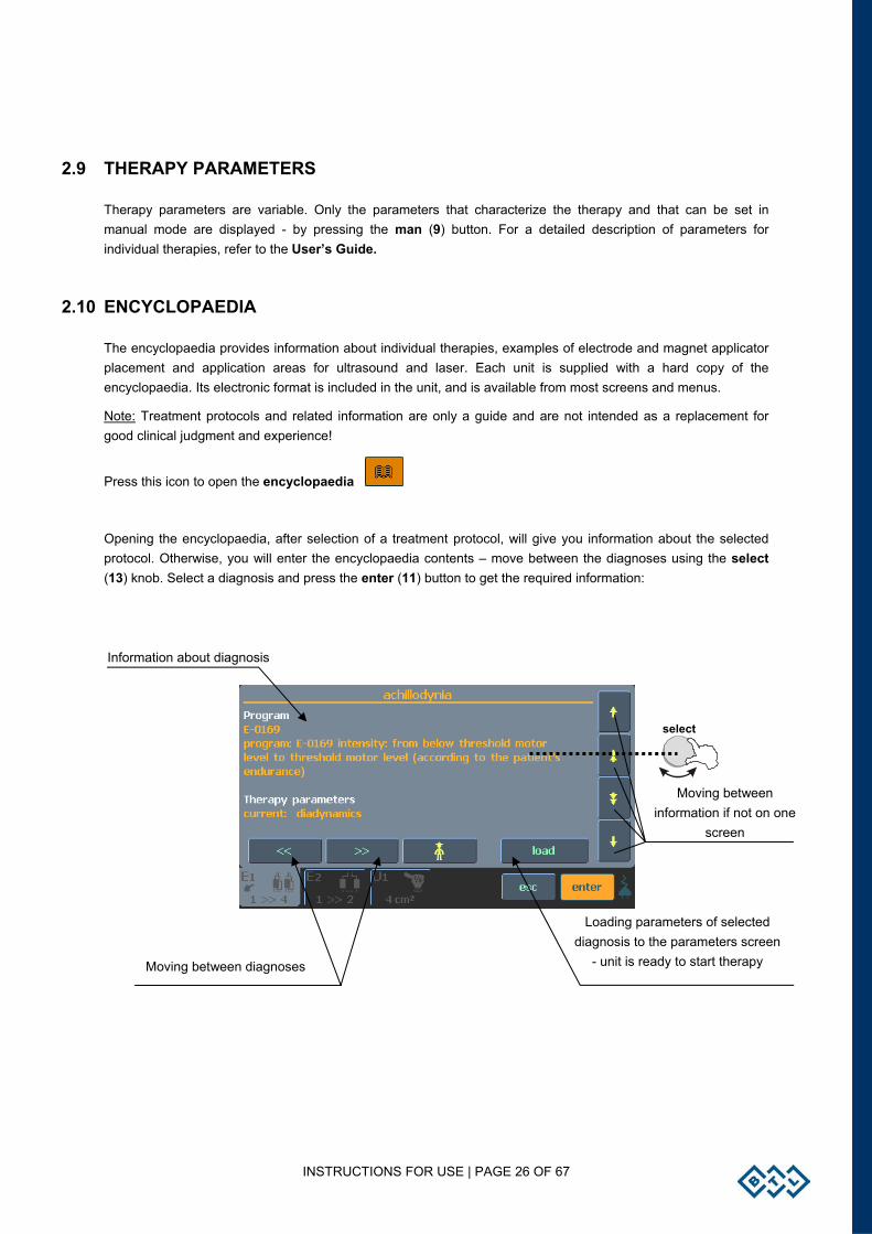
Opening the encyclopaedia, after selection of a treatment protocol, will give you information about the selected protocol. Otherwise, you will enter the encyclopaedia contents – move between the diagnoses using the select (13) knob. Select a diagnosis and press the enter (11) button to get the required information:
Loading parameters of selected diagnosis to the parameters screen
- unit is ready to start therapy
Information about diagnosis
Moving between diagnoses
Moving between information if not on one
screen
select
INSTRUCTIONS FOR USE | PAGE 27 OF 67
2.11 THERAPY SAVING
Pressing the save/copy button allows you to make several choices. Simply complete the form by entering the required data field as shown on the screens below.
2.11.1 SAVE THERAPY
You can save your therapy after setting therapy parameters from the therapy parameters screen – see the chapter Therapy Parameters Screen – Ergonomic, Standard and Expert Mode. The following information is saved with each therapy:
Electrotherapy: • All parameters of currents (pulse length, pause length, modulation, etc.) • Therapy time • Polarity • Output mode (current / voltage)*
Ultrasound therapy: • All therapy parameters (for example, ultrasound frequency, duty factor - DF, pulse frequency,
etc.) • Therapy time • Intensity
Combined therapies electro + ultrasound: • All electrotherapy parameters (pulse length, pause length, modulation, etc.) • All ultrasound therapy parameters (ultrasound frequency, duty factor - DF, pulse frequency,
etc.) • Therapy time • Polarity of electrotherapy output • Electrotherapy output mode (current / voltage) • Intensity of ultrasound*
Laser therapy: • All therapy parameters (frequency, course of signal, etc.) • Irradiated area • Dosage
Magnetotherapy: • All magnetotherapy parameters (pulse, pause, modulation, random frequency) • Pulse shapes • Therapy time • Intensity of magnetic field
* output intensity can be entered in a comment (e.g. at threshold motor level)
When saving a therapy, enter: • Name of diagnosis (therapy) – to be displayed in the list of user diagnoses – after pressing the diag/prog (8)
button once and selecting user diagnoses/programs • Number of program – to be displayed in the list of programs - after pressing the diag/prog (8) button twice • Description, additional information – to be displayed in both lists.
INSTRUCTIONS FOR USE | PAGE 28 OF 67
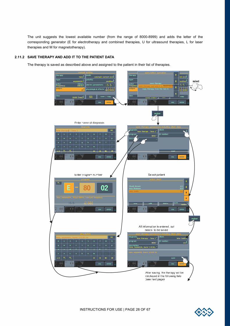
The unit suggests the lowest available number (from the range of 8000-8999) and adds the letter of the corresponding generator (E for electrotherapy and combined therapies, U for ultrasound therapies, L for laser therapies and M for magnetotherapy).
2.11.2 SAVE THERAPY AND ADD IT TO THE PATIENT DATA
The therapy is saved as described above and assigned to the patient in their list of therapies.
INSTRUCTIONS FOR USE | PAGE 29 OF 67
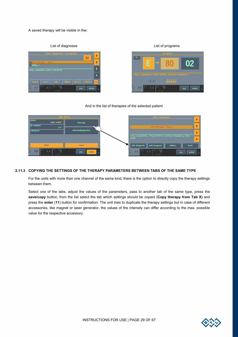
A saved therapy will be visible in the:
List of diagnoses List of programs
And in the list of therapies of the selected patient
2.11.3 COPYING THE SETTINGS OF THE THERAPY PARAMETERS BETWEEN TABS OF THE SAME TYPE
For the units with more than one channel of the same kind, there is the option to directly copy the therapy settings between them.
Select one of the tabs, adjust the values of the parameters, pass to another tab of the same type, press the save/copy button, from the list select the tab which settings should be copied (Copy therapy from Tab X) and press the enter (11) button for confirmation. The unit tries to duplicate the therapy settings but in case of different accessories, like magnet or laser generator, the values of the intensity can differ according to the max. possible value for the respective accessory.
INSTRUCTIONS FOR USE | PAGE 30 OF 67
2.12 INTERCONNECTION OF UNITS
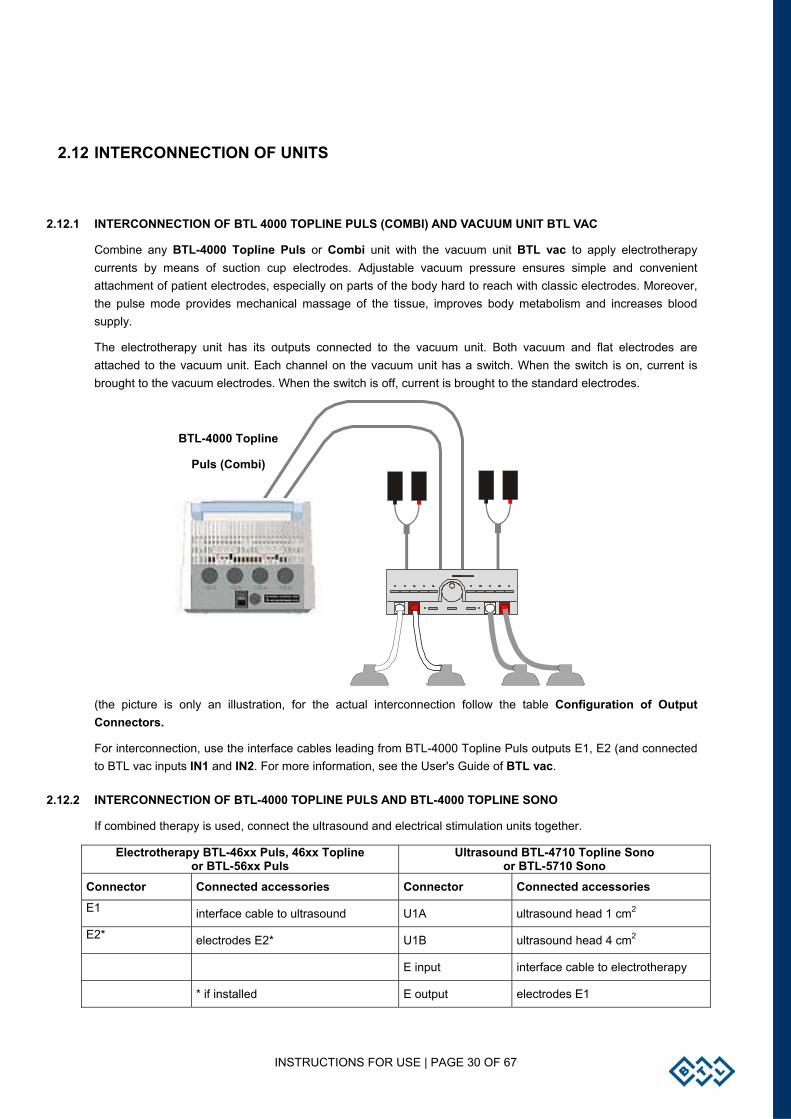
2.12.1 INTERCONNECTION OF BTL 4000 TOPLINE PULS (COMBI) AND VACUUM UNIT BTL VAC
Combine any BTL-4000 Topline Puls or Combi unit with the vacuum unit BTL vac to apply electrotherapy currents by means of suction cup electrodes. Adjustable vacuum pressure ensures simple and convenient attachment of patient electrodes, especially on parts of the body hard to reach with classic electrodes. Moreover, the pulse mode provides mechanical massage of the tissue, improves body metabolism and increases blood supply.
The electrotherapy unit has its outputs connected to the vacuum unit. Both vacuum and flat electrodes are attached to the vacuum unit. Each channel on the vacuum unit has a switch. When the switch is on, current is brought to the vacuum electrodes. When the switch is off, current is brought to the standard electrodes.
(the picture is only an illustration, for the actual interconnection follow the table Configuration of Output Connectors.
For interconnection, use the interface cables leading from BTL-4000 Topline Puls outputs E1, E2 (and connected to BTL vac inputs IN1 and IN2. For more information, see the User's Guide of BTL vac.
2.12.2 INTERCONNECTION OF BTL-4000 TOPLINE PULS AND BTL-4000 TOPLINE SONO
If combined therapy is used, connect the ultrasound and electrical stimulation units together.
Electrotherapy BTL-46xx Puls, 46xx Topline or BTL-56xx Puls
Ultrasound BTL-4710 Topline Sono or BTL-5710 Sono
Connector Connected accessories Connector Connected accessories
E1 interface cable to ultrasound U1A ultrasound head 1 cm2
E2* electrodes E2* U1B ultrasound head 4 cm2
E input interface cable to electrotherapy
* if installed E output electrodes E1
BTL-4000 Topline
Puls (Combi)
INSTRUCTIONS FOR USE | PAGE 31 OF 67
Setting of polarity between the ultrasound head and the electrode
After interconnection with the electrotherapy device, the ultrasound head becomes the anode (+). The other pole is the cathode (-) which is the electrode with the black banana plug. If the ultrasound head is required to be the cathode (-) during combined therapy, select ‘negative polarity’ in the therapy parameters screen of the electrotherapy unit.
ATTENTION
In the case of accessories „1>>2“connected to the electrotherapy device, the ultrasound head becomes the anode (+). The cathode (-) is connected thru the black banana plug with minus sign “-„ on it.
In the case of accessories „1>>4“” (optional) connected to the electrotherapy device, the ultrasound head becomes the anode (+). The cathode (-) is connected thru red banana plug with minus sign “+„ on it, independent of selected output A or B.
If you want to apply only electrotherapy with such interconnected devices, it is no problem. Uncheck the option "with electro" on the BTL-4000 Topline Sono device, and the electrotherapy electrodes are automatically connected to the electrotherapy output. Connectors E-input and E-output are interconnected inside the ultrasound device even if the BTL-4000 Topline Sono device is off.
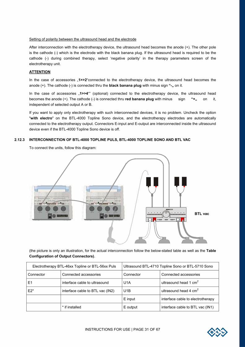
2.12.3 INTERCONNECTION OF BTL-4000 TOPLINE PULS, BTL-4000 TOPLINE SONO AND BTL VAC
To connect the units, follow this diagram:
(the picture is only an illustration, for the actual interconnection follow the below-stated table as well as the Table Configuration of Output Connectors).
Electrotherapy BTL-46xx Topline or BTL-56xx Puls Ultrasound BTL-4710 Topline Sono or BTL-5710 Sono
Connector Connected accessories Connector Connected accessories
E1 interface cable to ultrasound U1A ultrasound head 1 cm2
E2* interface cable to BTL vac (IN2) U1B ultrasound head 4 cm2
E input interface cable to electrotherapy
* if installed E output interface cable to BTL vac (IN1)
BTL vac
INSTRUCTIONS FOR USE | PAGE 32 OF 67
2.12.4 SETUP AND OPERATION OF COMBINED THERAPY IN INDIVIDUAL DEVICES
After checking for correct interconnection of the electrotherapy and ultrasound units, select a diagnosis or program that utilizes combined therapy. Select these separately on the electrotherapy and on the ultrasound units. Set the electrotherapy unit to CV mode. Then attach the respective electrode to the patient to close the electric circuit ultrasound head-patient-electrode (see the above diagrams). It is now possible to run the ultrasound by the start button. Position the ultrasound head in contact with tissue and notice that the timer commences counting down. Slowly increase the intensity on the electrotherapy by turning the select knob to the right in the "+" direction. Combined therapy is now running. If the contact between the ultrasound head and the treated tissue during the therapy was not continuous, the times shown on both devices can differ, because timer countdown on the ultrasound device does not run when the contact is interrupted.
2.12.5 STOPPING COMBINED THERAPY IN INDIVIDUAL DEVICES
Delivery of combined therapy ends after expiration of the set time on both units' timer devices. To stop or interrupt therapy before the set time expires, it is necessary first to interrupt the therapy on both units by pressing the stop buttons.
MENU BUTTON | PAGE 33 OF 67
3 MENU BUTTON
Press the menu (10) button, and two options appear, menu and user. Enter the menu option and scroll through the following options:
• accessories
• encyclopaedia – see chapter Encyclopaedia
• unit settings
• special settings
3.1 ACCESSORIES
The available options are:
• installation of accessories
• information about connected accessories
• information about the number of patients and connection of connectors on the rear panel of the device
3.1.1 INSTALLATION OF ACCESSORIES
Each connected accessory has a memory that includes identification data of this accessory. According to these data, the unit recognizes which accessory is connected, if it is compatible or not, if the unit can work with the connected accessory or not. The memory also contains the serial number of the accessory. This memory contains a lot of information and reading it takes from 30 seconds to 2 minutes. The installation of accessories serves for faster functioning of the unit. After the installation, only the serial number of the accessory is read from the accessory memory and the other information is read from the unit’s memory.
During the installation process, follow the instructions on the screen. In particular:
• switch off all therapies
• do not have connected other accessories than the one that is being installed. Make sure the installed accessory is connected directly, not via interface cable and vacuum or BTL-4000 Topline Sono devices.
This will help decrease electromagnetic interference, which could cause improper reading of memory data.
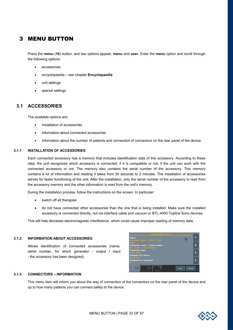
3.1.2 INFORMATION ABOUT ACCESSORIES
Allows identification of connected accessories (name, serial number, for which generator - output / input - the accessory has been designed).
3.1.3 CONNECTORS – INFORMATION
This menu item will inform you about the way of connection of the connectors on the rear panel of the device and up to how many patients you can connect safely to the device.
MENU BUTTON | PAGE 34 OF 67
3.2 UNIT SETTINGS
Provide a list of settings of parameters and user preferences: • Password setting • Sound setting • Screen saver and auto switch-off • Colour settings • Display options - setting contrast of LCD screen, back light and the small displays (which show the time and intensity of the running therapy ) • Date and time setting • Language setting • Operation mode • Touch panel calibration • User options • Style of operation • Setting of HW key • Unit Information • Unlock code • Service functions
3.2.1 PASSWORD SETTING
Changes the password required to operate the unit after power-up. The units as standard come with this function disabled.
If the unit includes a laser generator - BTL-4000 Topline Laser, BTL-48xx Topline L, BTL-4800 Topline xL, you cannot disable the password code (in compliance with the applicable standards). In this case, the four-digit code is factory-set to 0000.
Note:
If you happen to forget the password, you can always use the universal one: "00000000"
3.2.2 SOUND SETTING
Sets audio signalling of buttons and provides warnings of various operational conditions (start of therapy, stop or pause of therapy). All audio tones can be switched off or modified as required.
Units with laser generator - BTL-4000 Topline Laser, BTL-48xx Topline L, BTL-4800 Topline xL, cannot have the audio tone of the running therapy switched off (in compliance with the applicable standards).
Volume can be set in the User options menu (see chapter User Options).
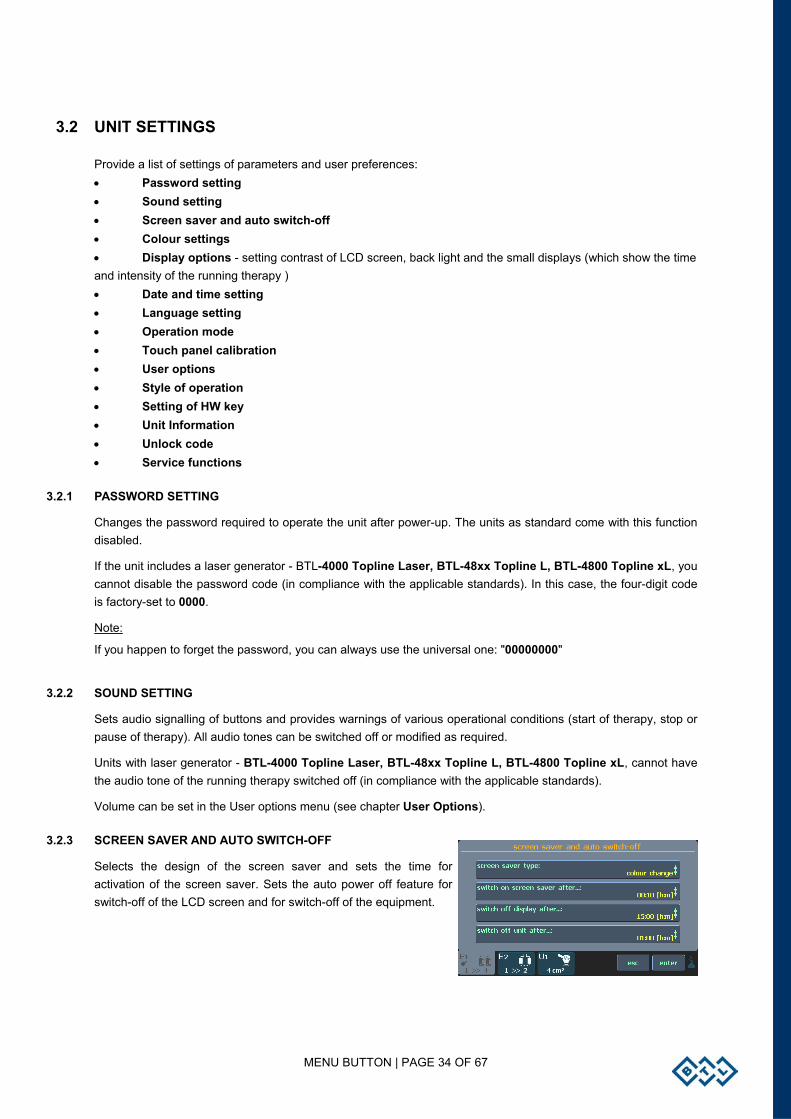
3.2.3 SCREEN SAVER AND AUTO SWITCH-OFF
Selects the design of the screen saver and sets the time for activation of the screen saver. Sets the auto power off feature for switch-off of the LCD screen and for switch-off of the equipment.
MENU BUTTON | PAGE 35 OF 67
3.2.4 SETTING OF COLOURS
The user can set the colours of all elements displayed on the screen: select one of the available preset colour schemes or, if not satisfied with any of them, create and save custom colour schemes. In the custom colour scheme, the user successively selects individual elements.
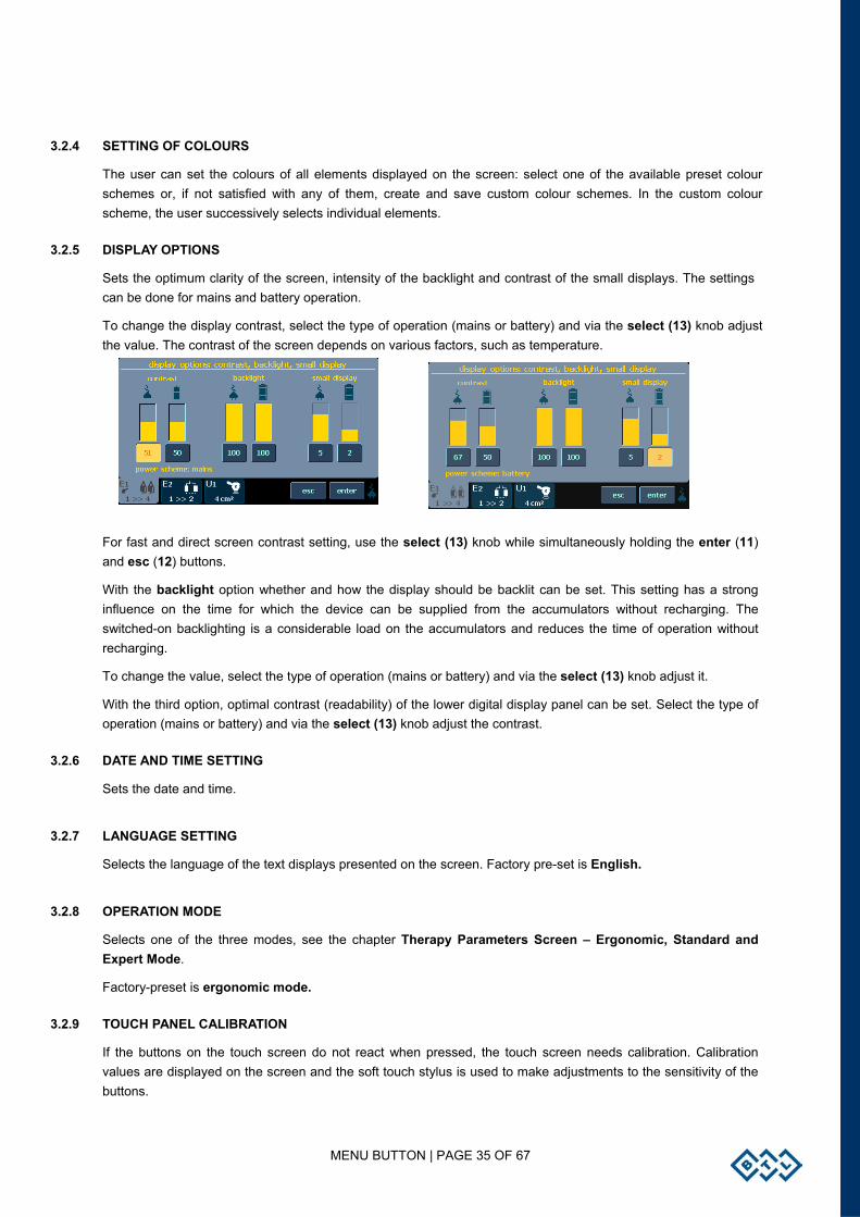
3.2.5 DISPLAY OPTIONS
Sets the optimum clarity of the screen, intensity of the backlight and contrast of the small displays. The settings can be done for mains and battery operation.
To change the display contrast, select the type of operation (mains or battery) and via the select (13) knob adjust the value. The contrast of the screen depends on various factors, such as temperature.
For fast and direct screen contrast setting, use the select (13) knob while simultaneously holding the enter (11) and esc (12) buttons.
With the backlight option whether and how the display should be backlit can be set. This setting has a strong influence on the time for which the device can be supplied from the accumulators without recharging. The switched-on backlighting is a considerable load on the accumulators and reduces the time of operation without recharging.
To change the value, select the type of operation (mains or battery) and via the select (13) knob adjust it.
With the third option, optimal contrast (readability) of the lower digital display panel can be set. Select the type of operation (mains or battery) and via the select (13) knob adjust the contrast.
3.2.6 DATE AND TIME SETTING
Sets the date and time.
3.2.7 LANGUAGE SETTING
Selects the language of the text displays presented on the screen. Factory pre-set is English.
3.2.8 OPERATION MODE
Selects one of the three modes, see the chapter Therapy Parameters Screen – Ergonomic, Standard and Expert Mode.
Factory-preset is ergonomic mode.
3.2.9 TOUCH PANEL CALIBRATION
If the buttons on the touch screen do not react when pressed, the touch screen needs calibration. Calibration values are displayed on the screen and the soft touch stylus is used to make adjustments to the sensitivity of the buttons.
MENU BUTTON | PAGE 36 OF 67
Press ‘ESC’ to stop calibration. To verify touch screen adjustments, use the "TOUCH PANEL FUNCTION TEST".
3.2.10 USER OPTIONS
It is possible to set:
• direction of cursor movement when using the select (13) control
• listing of therapies and some other menu options (in ascending or descending alphabetical order)
• location of the tab bar (up / down)
• speaker volume
3.2.11 STYLE OF OPERATION
• NEW STYLE OF OPERATION
Keep this option set to YES
• END OF THERAPY – SETTING ZERO INTENSITY AND TIME VALUES
After the end of therapy, you can have displayed either zero values of intensity and time or the intensity and time values of the last performed therapy.
• ZERO INTENSITY FOR SEQUENCE
This option controls whether a sequence can be interrupted by reducing its intensity. If set to yes, the sequence can be interrupted by decreasing the intensity to 0mA/V. When the option is set to no, and the intensity of a running sequence is reduced, it decreases minimally to 0.1mA/V and the therapy continues.
• REPEAT SOUND FOR END
Sets whether the sound for the end of therapy shall be repeated or not.
3.2.12 SETTING OF HW KEY
Via this option the type of unit can be changed by inserting a special 64-digit code.
3.2.13 UNIT INFORMATION
Displays info about the unit (serial number, firmware version, etc.). It also contains information till when the device will work – so called "device validity". If the functioning of the device is temporary, this item contains information until which date the device will be fully functional.
3.2.13 UNLOCK CODE
If the functioning of the device is temporary, in this item the code which can prolong the functionality of the unit or will remove the time restriction can be inserted.
3.2.14 SERVICE FUNCTIONS
• REPAIR OF FILES
Checks the file system in the unit and repairs possible errors - deletes empty files, etc. Recommended for use in case of lack of memory, if the unit refuses to save data, or if you think that some data have been lost.
• FILE SYSTEM FORMATTING
Clears all data and programs created by the user. You may select this function if the “repair of files” function did not help.
MENU BUTTON | PAGE 37 OF 67
• DELETE ACCESSORIES
Deletes all installed accessories. Use only in case of improper installation – corrupted accessory image on the channel tab, connected accessories are not detected (the “?” symbol is displayed), etc.
• DEFAULT SETTING WITHOUT LOSING USER DATA
All factory settings are restored. User data, such as patients, therapies, etc. are preserved.
• GENERS INFO
Shows information about the generators in the unit - their type, ID, FW version, position (master or slave) and temperature.
• INFORMATION ON FREE SPACE FOR USER DATA
The bottom part of the screen displays the current free space in the memory that can be used for user data. User data are, for example, patients, saved user diagnoses, I/t curves, etc.
The user can use the memory marked "E:"; the memory marked "S:" and “L:” are intended for internal use.
3.3 SPECIAL SETTINGS
Variable for each generator. See your User’s Guide for details.
USER SETTINGS OPTION | PAGE 38 OF 67
4 USER SETTINGS OPTION
Press menu, select the user settings option - opens a screen allowing access to special features of the unit, as well as to data saved by the user. The following items can be selected:
• clients • user sequences • user diagnoses / programs • recent therapies • motor point detection* • rheobasis – chronaxie* • accommodation coefficient* • I/t curve* * Available only with electrical stimulator equipped with electrodiagnostics (optional).
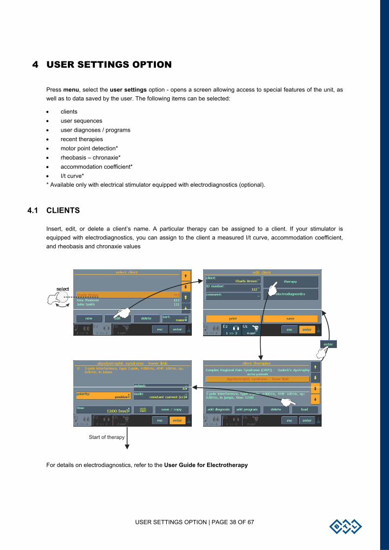
4.1 CLIENTS
Insert, edit, or delete a client’s name. A particular therapy can be assigned to a client. If your stimulator is equipped with electrodiagnostics, you can assign to the client a measured I/t curve, accommodation coefficient, and rheobasis and chronaxie values
Start of therapy
For details on electrodiagnostics, refer to the User Guide for Electrotherapy
USER SETTINGS OPTION | PAGE 39 OF 67
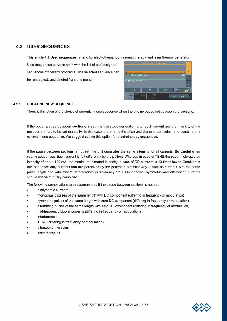
4.2 USER SEQUENCES
This article 4.2 User sequences is valid for electrotherapy, ultrasound therapy and laser therapy generator.
User sequences serve to work with the list of self-designed
sequences of therapy programs. The selected sequence can
be run, edited, and deleted from this menu.
4.2.1 CREATING NEW SEQUENCE
There is limitation of the choice of currents in one sequence when there is no pause set between the sections:
If the option pause between sections is set, the unit stops generation after each current and the intensity of the next current has to be set manually. In this case, there is no limitation and the user can select and combine any current in one sequence. We suggest setting this option for electrotherapy sequences.
If the pause between sections is not set, the unit generates the same intensity for all currents. Be careful when setting sequences. Each current is felt differently by the patient. Whereas in case of TENS the patient tolerates an intensity of about 100 mA, the maximum tolerated intensity in case of DD currents is 10 times lower. Combine in one sequence only currents that are perceived by the patient in a similar way – such as currents with the same pulse length and with maximum difference in frequency 1:10. Monophasic, symmetric and alternating currents should not be mutually combined.
The following combinations are recommended if the pause between sections is not set: • diadynamic currents • monophasic pulses of the same length with DC component (differing in frequency or modulation) • symmetric pulses of the same length with zero DC component (differing in frequency or modulation) • alternating pulses of the same length with zero DC component (differing in frequency or modulation) • mid-frequency bipolar currents (differing in frequency or modulation) • interferences • TENS (differing in frequency or modulation) • ultrasound therapies • laser therapies
USER SETTINGS OPTION | PAGE 40 OF 67
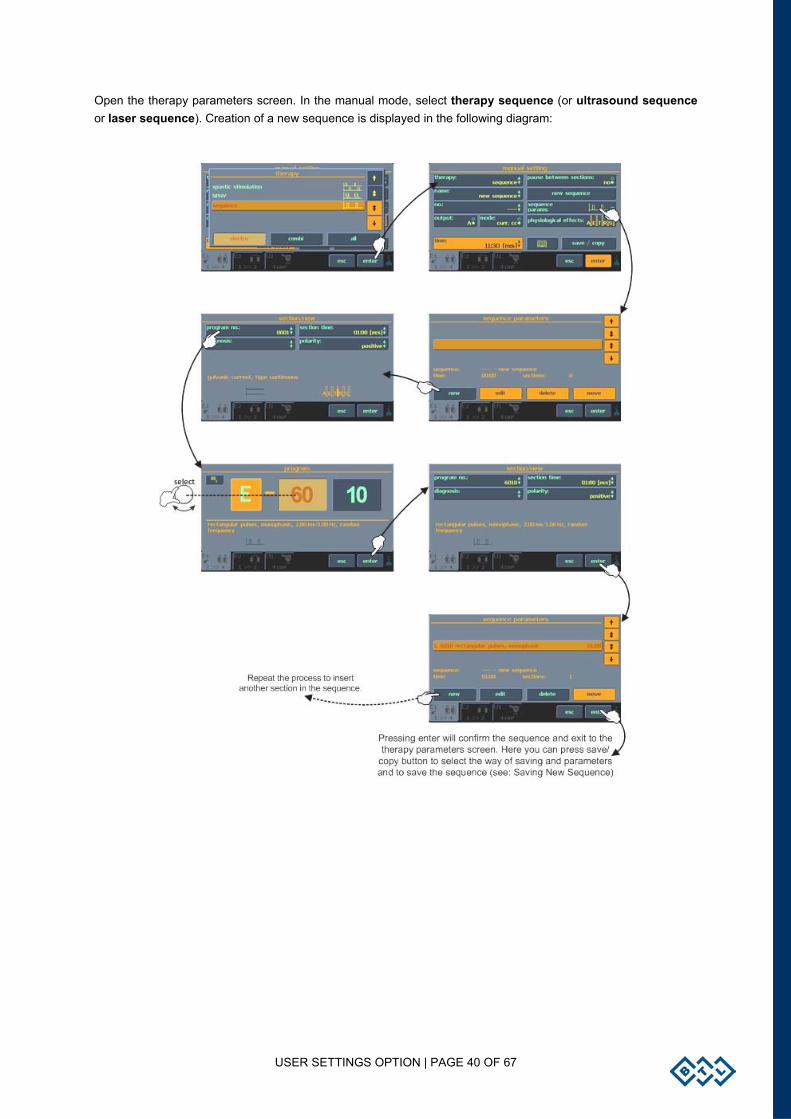
Open the therapy parameters screen. In the manual mode, select therapy sequence (or ultrasound sequence or laser sequence). Creation of a new sequence is displayed in the following diagram:
USER SETTINGS OPTION | PAGE 41 OF 67
4.2.2 PARAMETERS OF SECTIONS IN SEQUENCE
A sequence consists of a few currents / programs that are called sections. Parameters of sections must be set when creating a sequence.
Each program includes basic current parameters such as frequency, pulse length, modulation, etc. For more information, please refer to the chapter Save Therapy. Set all data in the manual setting screen and save them as a user-designed program (diagnosis). Insert the program/diagnoses in the sequence. Set the length of time of the section when inserting the program/diagnoses in the sequence (except laser, where the time of the section depends on the currently connected laser probe). Obviously, the factory-preset programs can also be inserted in the sequences. In the section only the polarity can be set (for electrotherapy sequence). The other parameters must be specified and saved in the inserted program.
Example: you want to create a sequence of diadynamic DF current (without base, positive polarity, CC mode, time of stimulation: 1 minute) and CP-ISO current (base 10%, reversal of polarity in the middle of the set time, CC mode, 10 minutes). Press man to select the manual mode, set diadynamic currents, DF type, without base, positive polarity, CC mode. Save this setting as (for example) program E-8001. Then set the parameters of the CP-ISO current: base 10%, positive, reversal, CC mode, and save it as (for example) program E-8002. Select therapy and press new sequence then press new, set the program number 8001, set the time of section 1:00, positive polarity, and press enter. Then add the second section in the same way – new, program number 8002, time of section 10:00, positive polarity with reversal, and press enter. Then press enter again to return to the manual settings screen, press save/copy and save the sequence (for example, as number 9501). The cv/cc mode is set globally for the whole sequence before starting it.
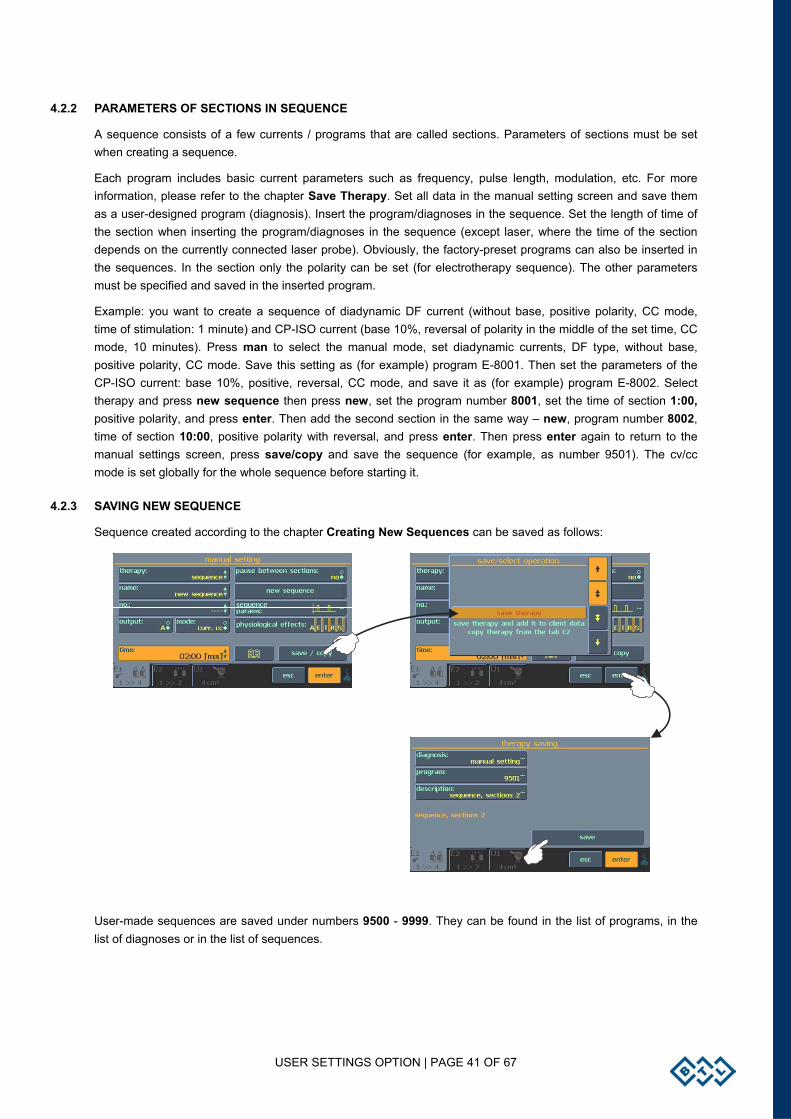
4.2.3 SAVING NEW SEQUENCE
Sequence created according to the chapter Creating New Sequences can be saved as follows:
User-made sequences are saved under numbers 9500 - 9999. They can be found in the list of programs, in the list of diagnoses or in the list of sequences.
USER SETTINGS OPTION | PAGE 42 OF 67
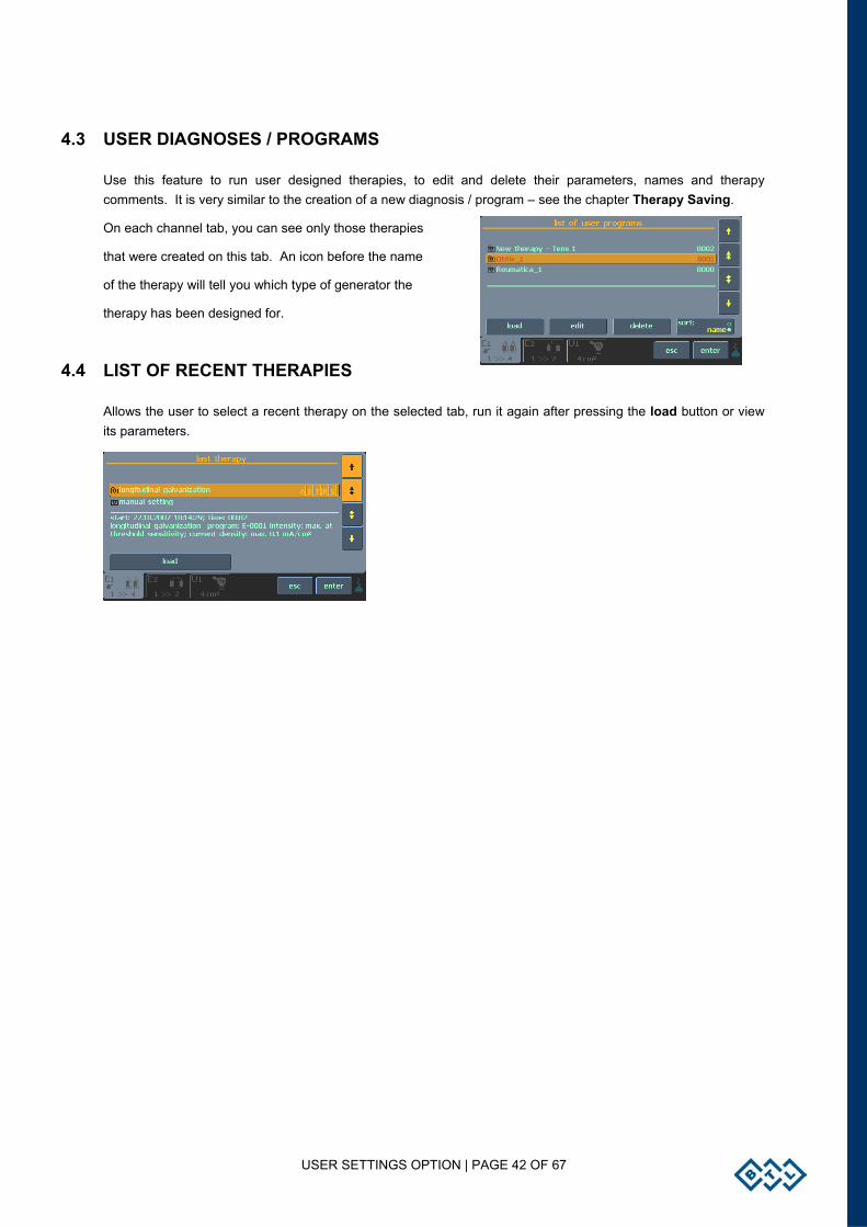
4.3 USER DIAGNOSES / PROGRAMS
Use this feature to run user designed therapies, to edit and delete their parameters, names and therapy comments. It is very similar to the creation of a new diagnosis / program – see the chapter Therapy Saving.
On each channel tab, you can see only those therapies
that were created on this tab. An icon before the name
of the therapy will tell you which type of generator the
therapy has been designed for.
4.4 LIST OF RECENT THERAPIES
Allows the user to select a recent therapy on the selected tab, run it again after pressing the load button or view its parameters.
ACCESSORIES | PAGE 43 OF 67
5 ACCESSORIES
The equipment is not designed for use in connection with other medical devices except those stated in this manual.
Following is a list of accessories that can be supplied with the units, both standard and optional. For detailed information on individual accessories, see the enclosed leaflet and/or the User's manual.
5.1 POWER SUPPLY ADAPTER 60W / ADAPTER 90W
The devices of the BTL-4000 Topline series can be connected to the mains exclusively via the supplied power supply Adapter 60W or Adapter 90W. Adapter 90W is more powerful and is used only for the connection of specific device configurations. Your device always includes the proper type of adapter.
It is forbidden to connect another adapter than mentioned to the device.
5.2 ACCUMULATOR
BTL-4000 Topline devices have a built-in accumulator. Its type is specified in the chapter Technical Parameters. Replacement of the accumulator is provided by the authorized service of BTL devices.
During operation, the accumulator is continuously being recharged from the mains. Its recharging and keeping charged is running even if the equipment is switched off and connected to the mains, and the mains switch (14) on the rear panel is in position I. At switching off, the device checks the status of the accumulators and if it finds them low, it switches to the charging mode; in the charging mode the display is dark and the main display shows the symbol of a recharging battery. After recharging of the accumulator, the device automatically switches off completely. Note that the charging process runs only if the device is plugged into the mains and the rocker mains switch (14) on the rear panel is in position I.
Determination of the accumulator status may take some time, therefore, the device may respond with a delay after switching off and then on again.
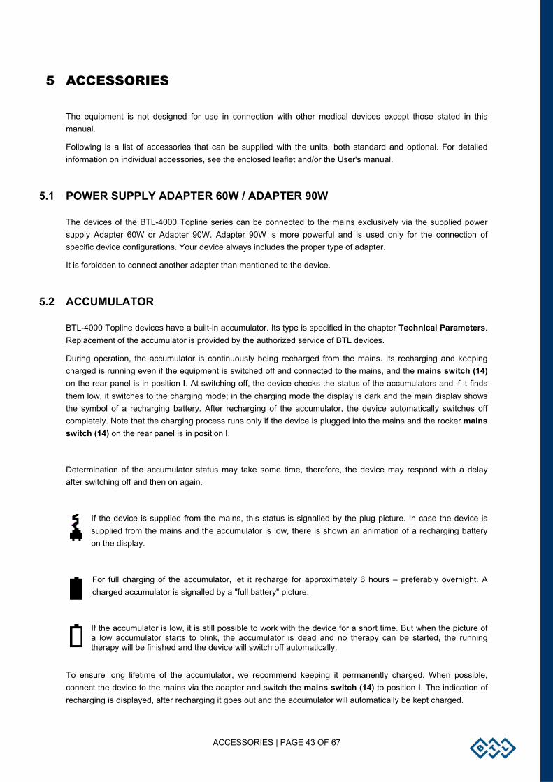
If the device is supplied from the mains, this status is signalled by the plug picture. In case the device is supplied from the mains and the accumulator is low, there is shown an animation of a recharging battery on the display.
For full charging of the accumulator, let it recharge for approximately 6 hours – preferably overnight. A charged accumulator is signalled by a "full battery" picture.
If the accumulator is low, it is still possible to work with the device for a short time. But when the picture of a low accumulator starts to blink, the accumulator is dead and no therapy can be started, the running therapy will be finished and the device will switch off automatically.
To ensure long lifetime of the accumulator, we recommend keeping it permanently charged. When possible, connect the device to the mains via the adapter and switch the mains switch (14) to position I. The indication of recharging is displayed, after recharging it goes out and the accumulator will automatically be kept charged.
ACCESSORIES | PAGE 44 OF 67
If the device is left unplugged from the mains for a longer time (even in the OFF status), the accumulators gradually spontaneously discharge. This effect is characteristic of the accumulators and cannot be removed; therefore, if the device has been off and unplugged for a longer time than approximately 2-3 months, we recommend recharging it, preferably for 48 hours without interruption.
For the same reason, we recommend charging the device continuously for at least 48 hours immediately after purchase, regardless of the accumulator status indication (you can work with the device normally, only do not unplug it from the adapter, the accumulator recharges even during standard operation of the device). Thus the accumulator becomes “formatted” and will keep working longer without recharging.
5.3 LITHIUM BATTERY
The device contains a lithium battery for backing up the date and time. The type of battery is stated in the chapter Technical Parameters. Replacement is provided by the authorized service of BTL devices.
5.4 ACCESSORIES COMMON FOR ALL UNITS
• External power supply Adapter 60W / Adapter 90W including the mains cable • Touch-pen • User’s manual • Markers for output cables • Cart
5.5 ACCESSORIES FOR ELECTROTHERAPY
• user’s guide for electrotherapy • patient cable BTL-236-1 • patient cable BTL-236-2 (optional) • flat rubber electrodes 7 x 5 cm2 • flat rubber electrodes 12 x 8 cm2 • sponge covers 7 x 5 cm2 • sponge covers 12 x 8 cm2 • set of fixation belts • point electrode - ball point attachment – diameter 2 mm - ball point attachment – diameter 6 mm - HVT attachment (only for BTL-4610 Topline and BTL-4615 Topline) • self-adhesive electrodes • vaginal electrode • rectal electrode • interface cable between BTL-4000 Topline and BTL vac
ACCESSORIES | PAGE 45 OF 67
5.6 ACCESSORIES FOR ULTRASOUND THERAPY
• user's guide for ultrasound therapy • 1cm2 ultrasound head BTL-237-1-13 for 1 and 3MHz, ERA 0.7 cm2 • 4cm2 ultrasound head BTL-237-4-13 for 1 and 3MHz, ERA 3.24 cm2 • ultrasound gel 235ml, 5l, 10l • interface cable between BTL-46xx Topline Puls and BTL-47xx Topline Sono
5.7 ACCESSORIES FOR LASER THERAPY
• user's guide for laser therapy • laser probes - red BTL-448 • laser probes – infrared BTL-448 • laser clusters - red BTL-445 • laser clusters - infrared BTL-445 • laser clusters - combined (red and infrared) BTL-445 • holder for laser probe and laser cluster • holder for optical attachment • optical attachments for laser probes • warning labels • safety goggles OPTE BS 2, L3, 630 – 1350nm
5.8 ACCESSORIES FOR MAGNETOTHERAPY
• user’s guide for magnetotherapy • disc applicator - BTL-239-1 • solenoid small applicator - BTL-239-2 • solenoid big applicator - BTL-239-3 • double disc applicator - BTL-239-4 • multi disc applicator - BTL-239-5 • linear applicator - BTL-239-6 • solenoid applicator ø70cm with couch- BTL-239-8 • interface cable for connection of old type of applicators from BTL-09
• fixation belts

MAINTENANCE AND SAFETY INSTRUCTIONS | PAGE 46 OF 67
6 MAINTENANCE AND SAFETY INSTRUCTIONS
The service inspection including measuring of all parameters of the device and possible recalibration must be performed at intervals shorter than 30 months. The inspection and recalibration is performed by the authorized BTL service department on the basis of the user's order. If the inspection is not done within the stated term, the manufacturer does not guarantee the technical parameters or safe operation of the product.
Safe operation of any item of medical equipment requires close attention to detail. Please check the following on a regular basis:
Power cord and plug: Check for frays and kinks. Ensure that the insulation is not damaged in any way.
Ultrasound head surface: Gel should always be thoroughly cleaned from the surface of the head. Always maintain this surface in as clean a condition as possible. Do not use any abrasive products for cleaning this surface as they could damage this delicate accessory.
Wires, cables and electrodes: Check for frays, cuts or tears in the insulation. Always route electrical cords and cables away from user or patient foot traffic areas where they could increase the chance of a tripping-related accident.
Check the unit before each use to determine that all controls function normally.
Calibration of heads and probes / clusters must be done by authorized personnel.
Cleaning
To keep the device clean, do not store or use it in a dusty environment and do not spill any liquid on the surface. To clean, turn the equipment off and unplug the power supply. Clean the unit with a damp cloth. Do not use abrasive materials. Do not use agents containing alcohol, ammonia, benzine, or thinners. Clean the accessories that come into contact with the patient after each treatment. Use appropriate agents. No part of the equipment needs to be aseptic or sterilized.
Laser probes/clusters: Keep the lens clean. After each application, wipe the head of the probe with a cotton cloth (divergent probes). Unscrew the head, wipe the lens and blow compressed air through the head (convergent probes). In laser clusters, wipe the laser aperture with a cotton cloth so as to keep the protective glass clean.
Laser optical attachments: Can be sterilized for 20 minutes at a temperature of 180°C.
Fuse replacement
A protective fuse is located inside the BTL-4000 Topline device. The type of fuse is specified in the chapter Technical Parameters. The user should not replace the fuse; for replacement of the fuse, always contact the authorized service of BTL devices.
Transport and Storage
We recommend keeping the original packaging of this equipment to ensure its maximum protection during transportation. Unplug the power supply adapter and the accessories cables. The equipment must be stored or transported as defined in the chapter Technical Parameters.
MAINTENANCE AND SAFETY INSTRUCTIONS | PAGE 47 OF 67
6.1 SAFETY
ATTENTION!
The consumed current or voltage of the connectors marked with this label can exceed safety values.
The protection of the equipment is BF-type floating applied part (only if original accessories including power supply Adapter 60W / Adapter 90W are used).
The equipment does not use any medicaments which would be an integral part or would be applied by means of it.
ATTENTION!
This system has no user-serviceable parts or assemblies. Do not remove the instrument covers under any circumstances. Call your distributor for advice about any malfunction.
The device is equipped with a protection system that prevents connection of accessories other than those supplied from the manufacturer.
General safety precautions:
• Before first switch-on of the equipment, carefully read the User's Manual.
• All staff who will use the equipment must be instructed in the way of operation, maintenance and checking of the equipment, and the safety principles.
• The electrical cabling which the equipment will be connected to must be installed and tested according to the existing valid standards (IEC 364). If you are not sure that the mains are completely OK, get them inspected by an inspection engineer.
• Check whether the parameters of the mains correspond to the requirements of the equipment according to the chapter Technical Parameters. It must not be used in an environment which implies the danger of explosion or penetration of water into the equipment. It must not be used in connection with flammable anaesthetics or oxidizing gasses (O2, N2O, etc.).
• Do not place the equipment in direct sunshine or strong electromagnetic fields so as to prevent undesirable mutual influence. In case this undesirable influence occurs, place the equipment further from the source of interference or contact the authorized service of BTL devices.
• Inspect the equipment thoroughly before each use (loose cables, broken insulation of cables, functions of displays and controls, etc.); in case of any inconsistency, stop using the equipment and contact the authorized BTL service department. If the equipment's behaviour differs from the function described in this Manual, stop using the equipment and contact the BTL service department.
• If the equipment shows any defect or if you have doubts about its correct functioning, terminate therapy immediately. If you do not determine the source of uncertainty after thorough study of the Manual, contact the BTL service department. If the equipment is not used in accord with this Manual or is used even if it shows functional differences from this Manual, the user is responsible for the damage caused by the equipment.
• Do not dismantle the equipment in any case; removal of the protective covers implies the danger of electrical injury. Replacement of the lithium battery, fuses or accumulators may only be done by the authorized BTL service department.
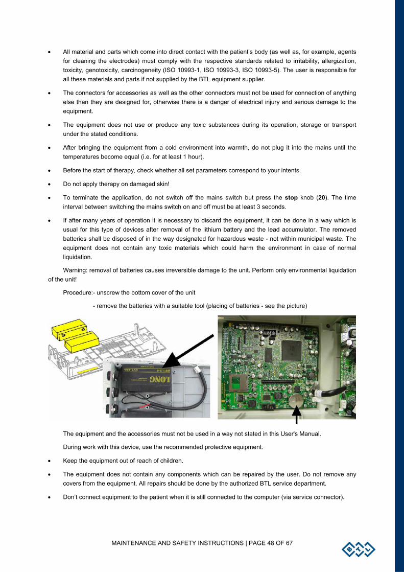
MAINTENANCE AND SAFETY INSTRUCTIONS | PAGE 48 OF 67
• All material and parts which come into direct contact with the patient's body (as well as, for example, agents for cleaning the electrodes) must comply with the respective standards related to irritability, allergization, toxicity, genotoxicity, carcinogeneity (ISO 10993-1, ISO 10993-3, ISO 10993-5). The user is responsible for all these materials and parts if not supplied by the BTL equipment supplier.
• The connectors for accessories as well as the other connectors must not be used for connection of anything else than they are designed for, otherwise there is a danger of electrical injury and serious damage to the equipment.
• The equipment does not use or produce any toxic substances during its operation, storage or transport under the stated conditions.
• After bringing the equipment from a cold environment into warmth, do not plug it into the mains until the temperatures become equal (i.e. for at least 1 hour).
• Before the start of therapy, check whether all set parameters correspond to your intents.
• Do not apply therapy on damaged skin!
• To terminate the application, do not switch off the mains switch but press the stop knob (20). The time interval between switching the mains switch on and off must be at least 3 seconds.
• If after many years of operation it is necessary to discard the equipment, it can be done in a way which is usual for this type of devices after removal of the lithium battery and the lead accumulator. The removed batteries shall be disposed of in the way designated for hazardous waste - not within municipal waste. The equipment does not contain any toxic materials which could harm the environment in case of normal liquidation.
Warning: removal of batteries causes irreversible damage to the unit. Perform only environmental liquidation of the unit!
Procedure:- unscrew the bottom cover of the unit
- remove the batteries with a suitable tool (placing of batteries - see the picture)
The equipment and the accessories must not be used in a way not stated in this User's Manual.
During work with this device, use the recommended protective equipment.
• Keep the equipment out of reach of children.
• The equipment does not contain any components which can be repaired by the user. Do not remove any covers from the equipment. All repairs should be done by the authorized BTL service department.
• Don’t connect equipment to the patient when it is still connected to the computer (via service connector).

MAINTENANCE AND SAFETY INSTRUCTIONS | PAGE 49 OF 67
Safety precautions for electrotherapy:
• When applying DC currents (the polarity button is enabled), it is necessary to pay attention to the set intensity and time of application of currents. Wrong values can cause burning of the patient's skin.
• The maximum secure effective value of current density on the electrodes is 2 mA/cm2 (according to IEC 601-2-10). BTL-4000 Topline Series can exceed this value (according to the place of used electrodes type). In such case it is necessary to pay greater attention to the application of currents! Wrong values can cause burning of the patient's skin.
• Application of electrodes near the thorax may increase the risk of cardiac fibrillation.
• For contraindications, see the chapter Contraindications. Use of electrotherapy in cases of contraindication must be approved by a specialist.
• Simultaneous connection of the patient to a high-frequency surgical device may cause burning in the place of the electrodes and possible damage to the electrotherapy device.
• Simultaneous connection of the patient to an ECG monitor or an ECG alarm system may cause temporary malfunctioning of the ECG systems or unreliability of the values measured by the ECG systems.
• Operation of the equipment close to (within 1 m of) a short-wave or micro-wave therapeutic device may cause instability of the equipment's output.
• All supplied electrodes can be used at the maximum intensity of currents and voltage that can be set on the device.
Safety precautions for ultrasound:
• Protect the heads consistently from shocks and frost. Do not unnecessarily bend the mains cable.
• During therapy, hold the head so that you do not touch its metallic parts.
• An impact on the metal part of the head as well as an intense impact on the head's case may negatively change the parameters of the therapeutic head.
• For contraindications, see chapter the Contraindications. Use of ultrasound therapy in cases of contraindication must be approved by a specialist.
• For therapy, use only the BTL ultrasound gel; the head is not tested for other gels or oils and their use could damage the head. If you still want to use other gels, we recommend them to be only water-based gels. Never use paraffin-based gels.
MAINTENANCE AND SAFETY INSTRUCTIONS | PAGE 50 OF 67
Safety precautions for laser:
• Mark the laser workplace with the respective warning notices and connect the door switch.
• Equip the laser workplace with an operating code which must be approved by a competent health officer.
• When using a laser probe with an output of 200 mW or more (300 mW, 400 mW) and if the laser power is set higher than 150 mW, the duration of therapy must not exceed 15 min.
• Attention – use of any other than the stated control and setting elements and processes may cause dangerous exposure to radiation.
• The equipment works with laser beam of the 3B class. When working with the beam, follow all the instructions stated in this Manual and in the laser therapy User's Guide. Prevent the laser beam from hitting the eyes, thyroid and other endocrine glands, the head, etc. (see the User's Guide). Both the therapist and the patient must wear the supplied protective goggles during therapy. Incorrect handling of the equipment (not in accord with this Manual) may cause dangerous radiation and even damage to the eyes! In such a case, the user is responsible for all damage.
• During radiation, do not disconnect the probe from the equipment and do not switch the equipment off.
• Protect the laser probe consistently from impacts!!!! The probe is not waterproof!
• Protect yourself and your surroundings from being directly hit by the laser beam.
• For contraindications, see the chapter Contraindications. Use of laser therapy in cases of contraindication must be approved by a specialist.
Safety precautions for magnet:
• Never use damaged applicators. Electric shock to personal or patient may occur.
• Attending personnel should keep away from the patient applicator side when the applicator is in use. The relevant channel should be switched off during necessary manipulation.
• Stop the therapy at once in case of any failure.
• Check all parameters before you start the therapy.
• Place the instrument on an even hard board to assure proper cooling.
• Watches, electronic devices and magnetic recording carriers can be damaged when closely exposed to applicators and cables.
• Do not connect anything else to the connectors – there is a danger of injury by electric shock and / or serious damage to the instrument.
• The instrument must not be used in the presence of pregnant women!

MAINTENANCE AND SAFETY INSTRUCTIONS | PAGE 51 OF 67
6.2 CONTRAINDICATIONS
The list of contraindications the cases when the manufacturer does not recommend applying the selected therapy. If a specialised medical workplace decides to apply the therapy in spite of it, they bear all the responsibility for this action.
6.2.1 CONTRAINDICATIONS FOR ELECTROTHERAPY
• Active tuberculosis
• Allergy to solutions used for dampening electrode cover sponges
• Applications in the area of the heart and eyes
• Groundless stimulation - "placebo effect"
• Cardiovascular diseases
• Electronic implants (i.e. Cochlear implants, neural implants, pacemaker, defibrillator, chip implants...)
• Metal implants
• Malignancies in the current path
• Skin defects and skin inflammations
• Bleeding conditions
• Menstruation
• Tumour diseases
• Sensitivity disorders (relative KI) in the area of electrode placement
• Psychopathological syndromes and organic psychosyndromes
• Multiple sclerosis
• Pregnancy
• Inflammations of veins and lymphatic paths
MAINTENANCE AND SAFETY INSTRUCTIONS | PAGE 52 OF 67
6.2.2 CONTRAINDICATIONS FOR ULTRASOUND
• Active tuberculosis
• Allergies to used ultrasound gels
• Applications on peripheral nerves (located on the bone, close to skin surface)
• Applications on glands with inner secretion
• Applications on areas around the eyes, brain, spinal cord
• Blood diseases
• Children - epiphyses of growing bones
• Gonads
• Pregnancy
• Pacemaker
• Cardiovascular diseases
• Cochlear implants
• Metal implants
• Skin defects and skin inflammations
• Bleeding conditions
• Menstruation
• Tumour diseases
• Blood circulation deficiency
• St. p. Laminectomii
6.2.3 CONTRAINDICATIONS FOR LASER THERAPY
• Applications in the area of the eyes – possibility of direct eye irradiation and retina damage
• Menstruation
• Tumour diseases
• Irradiation of malignancies and potentially precancerous growths
• Irradiation of patients with cochlear implants
• Irradiation of glands with inner secretion
• Patients with febrile conditions
• Pulse modes (both red and infrared beam) are not used on patients with anamnesis of epilepsy
• Pregnancy
MAINTENANCE AND SAFETY INSTRUCTIONS | PAGE 53 OF 67
•
6.2.4 CONTRAINDICATIONS FOR MAGNETOTHERAPY
• Bleeding conditions, hypothalamus and hypophysis disorders
• Electronic implants (i.e. Cochlear implants, neural implants, pacemaker, defibrillator, chip implants...)
• Hyperthyroidism, hyperfunction of adrenals, myastenia gravis
• Malignancies
• Menstruation
• Metal implants
• Onychomycosis
• Paroxysm neurologic diseases
• Pregnancy
• Psychoses
• Serious mycosis, active tuberculosis, acute virosis
• Special attention must be paid to patients with hypotonia or otherwise with hypertension
• Tumour diseases
• Children – growth discs of bones (epiphysis)
6.3 USEFUL ADDRESSES
The product is manufactured in accordance with the EU Medical Devices Directive by:
BTL Industries Ltd.
161 Cleveland Way
Stevenage
Hertfordshire, SG1 6BU United Kingdom
E-mail: [email protected]
http://www.btlnet.com
For service, please contact the service department at [email protected].
6.4 WARRANTY
The Manufacturer of this product guarantees the product is free of defects in workmanship and material for the period and conditions defined in the BTL General Service Conditions.
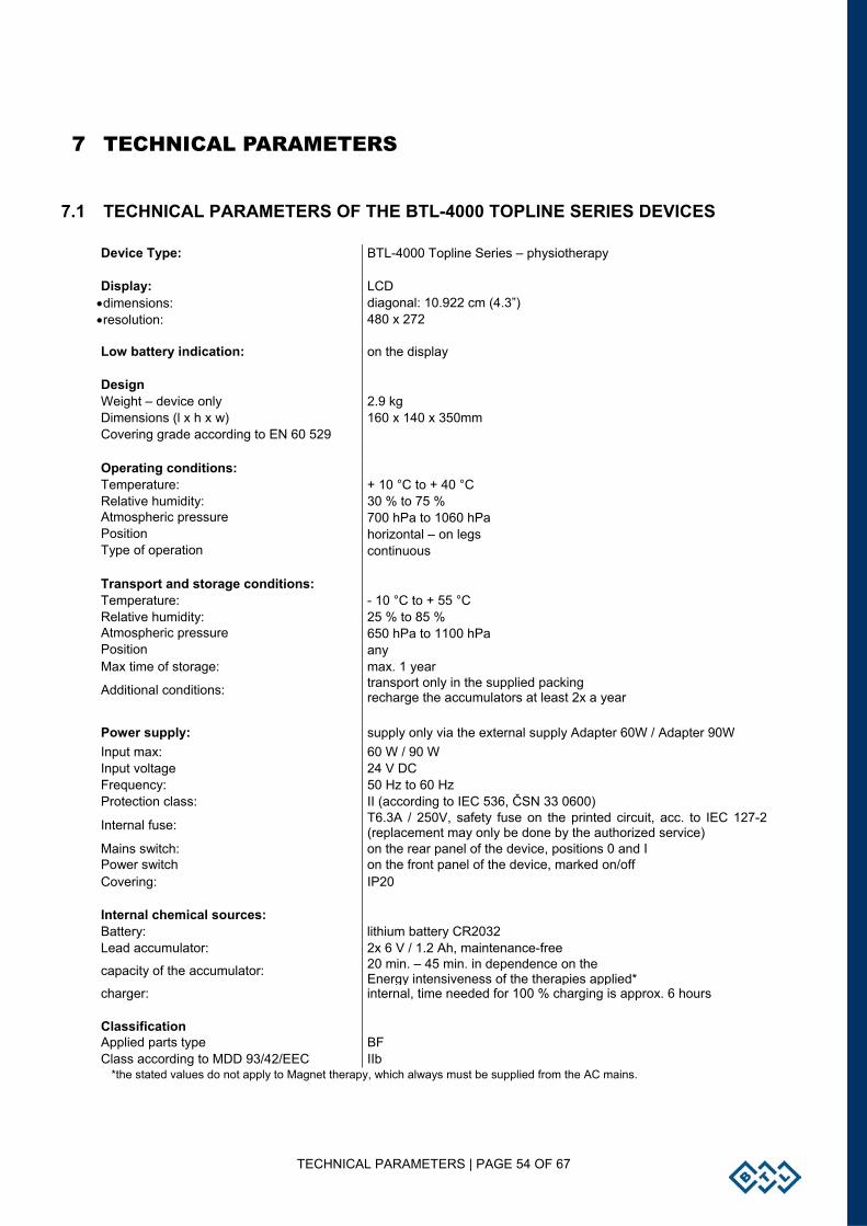
TECHNICAL PARAMETERS | PAGE 54 OF 67
7 TECHNICAL PARAMETERS
7.1 TECHNICAL PARAMETERS OF THE BTL-4000 TOPLINE SERIES DEVICES
Device Type: BTL-4000 Topline Series – physiotherapy Display: LCD
•dimensions: diagonal: 10.922 cm (4.3”) •resolution: 480 x 272 Low battery indication: on the display Design Weight – device only 2.9 kg Dimensions (l x h x w) 160 x 140 x 350mm Covering grade according to EN 60 529 Operating conditions: Temperature: + 10 °C to + 40 °C Relative humidity: 30 % to 75 % Atmospheric pressure 700 hPa to 1060 hPa Position horizontal – on legs Type of operation continuous Transport and storage conditions: Temperature: - 10 °C to + 55 °C Relative humidity: 25 % to 85 % Atmospheric pressure 650 hPa to 1100 hPa Position any Max time of storage: max. 1 year
Additional conditions: transport only in the supplied packing recharge the accumulators at least 2x a year
Power supply: supply only via the external supply Adapter 60W / Adapter 90W Input max: 60 W / 90 W Input voltage 24 V DC Frequency: 50 Hz to 60 Hz Protection class: II (according to IEC 536, ČSN 33 0600)
Internal fuse: T6.3A / 250V, safety fuse on the printed circuit, acc. to IEC 127-2 (replacement may only be done by the authorized service)
Mains switch: on the rear panel of the device, positions 0 and I Power switch on the front panel of the device, marked on/off Covering: IP20 Internal chemical sources: Battery: lithium battery CR2032 Lead accumulator: 2x 6 V / 1.2 Ah, maintenance-free
capacity of the accumulator: 20 min. – 45 min. in dependence on the Energy intensiveness of the therapies applied*
charger: internal, time needed for 100 % charging is approx. 6 hours Classification Applied parts type BF Class according to MDD 93/42/EEC IIb
*the stated values do not apply to Magnet therapy, which always must be supplied from the AC mains.
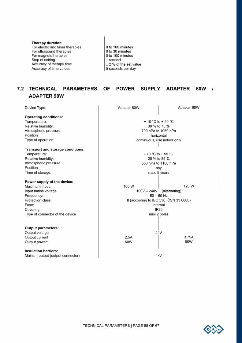
TECHNICAL PARAMETERS | PAGE 55 OF 67
Therapy duration For electro and laser therapies 0 to 100 minutes For ultrasound therapies 0 to 30 minutes For magnetotherapies 0 to 100 minutes Step of setting 1 second Accuracy of therapy time ± 2 % of the set value Accuracy of time values 5 seconds per day
7.2 TECHNICAL PARAMETERS OF POWER SUPPLY ADAPTER 60W / ADAPTER 90W
Device Type: Adapter 60W Adapter 90W Operating conditions: Temperature: + 10 °C to + 40 °C Relative humidity: 30 % to 75 % Atmospheric pressure 700 hPa to 1060 hPa Position horizontal Type of operation continuous, use indoor only Transport and storage conditions: Temperature: - 10 °C to + 55 °C Relative humidity: 25 % to 85 % Atmospheric pressure 650 hPa to 1100 hPa Position any Time of storage: max. 5 years Power supply of the device: Maximum input: 100 W 120 W Input mains voltage 100V – 240V ~ (alternating) Frequency: 50 – 60 Hz Protection class: II (according to IEC 536, ČSN 33 0600) Fuse: internal Covering: IP20 Type of connector of the device mini 2 poles Output parameters: Output voltage 24V Output current 2.5A 3.75A Output power: 60W 90W Insulation barriers: Mains – output (output connector) 4kV
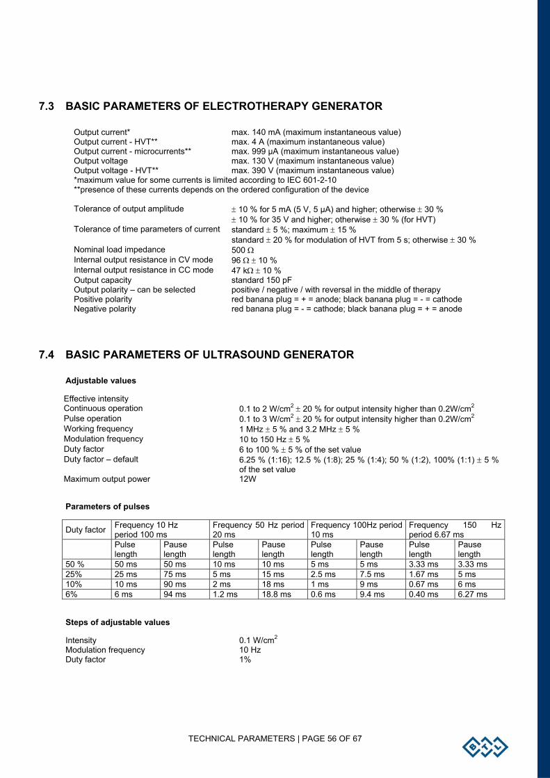
TECHNICAL PARAMETERS | PAGE 56 OF 67
7.3 BASIC PARAMETERS OF ELECTROTHERAPY GENERATOR
Output current* max. 140 mA (maximum instantaneous value) Output current - HVT** max. 4 A (maximum instantaneous value) Output current - microcurrents** max. 999 µA (maximum instantaneous value) Output voltage max. 130 V (maximum instantaneous value) Output voltage - HVT** max. 390 V (maximum instantaneous value) *maximum value for some currents is limited according to IEC 601-2-10 **presence of these currents depends on the ordered configuration of the device Tolerance of output amplitude ± 10 % for 5 mA (5 V, 5 µA) and higher; otherwise ± 30 % ± 10 % for 35 V and higher; otherwise ± 30 % (for HVT) Tolerance of time parameters of current standard ± 5 %; maximum ± 15 % standard ± 20 % for modulation of HVT from 5 s; otherwise ± 30 % Nominal load impedance 500 Ω Internal output resistance in CV mode 96 Ω ± 10 % Internal output resistance in CC mode 47 kΩ ± 10 % Output capacity standard 150 pF Output polarity – can be selected positive / negative / with reversal in the middle of therapy Positive polarity red banana plug = + = anode; black banana plug = - = cathode Negative polarity red banana plug = - = cathode; black banana plug = + = anode
7.4 BASIC PARAMETERS OF ULTRASOUND GENERATOR
Adjustable values
Effective intensity Continuous operation 0.1 to 2 W/cm2 ± 20 % for output intensity higher than 0.2W/cm2 Pulse operation 0.1 to 3 W/cm2 ± 20 % for output intensity higher than 0.2W/cm2 Working frequency 1 MHz ± 5 % and 3.2 MHz ± 5 % Modulation frequency 10 to 150 Hz ± 5 % Duty factor 6 to 100 % ± 5 % of the set value Duty factor – default 6.25 % (1:16); 12.5 % (1:8); 25 % (1:4); 50 % (1:2), 100% (1:1) ± 5 %
of the set value Maximum output power 12W
Parameters of pulses
Duty factor Frequency 10 Hz period 100 ms
Frequency 50 Hz period 20 ms
Frequency 100Hz period 10 ms
Frequency 150 Hz period 6.67 ms
Pulse length
Pause length
Pulse length
Pause length
Pulse length
Pause length
Pulse length
Pause length
50 % 50 ms 50 ms 10 ms 10 ms 5 ms 5 ms 3.33 ms 3.33 ms 25% 25 ms 75 ms 5 ms 15 ms 2.5 ms 7.5 ms 1.67 ms 5 ms 10% 10 ms 90 ms 2 ms 18 ms 1 ms 9 ms 0.67 ms 6 ms 6% 6 ms 94 ms 1.2 ms 18.8 ms 0.6 ms 9.4 ms 0.40 ms 6.27 ms
Steps of adjustable values
Intensity 0.1 W/cm2 Modulation frequency 10 Hz Duty factor 1%
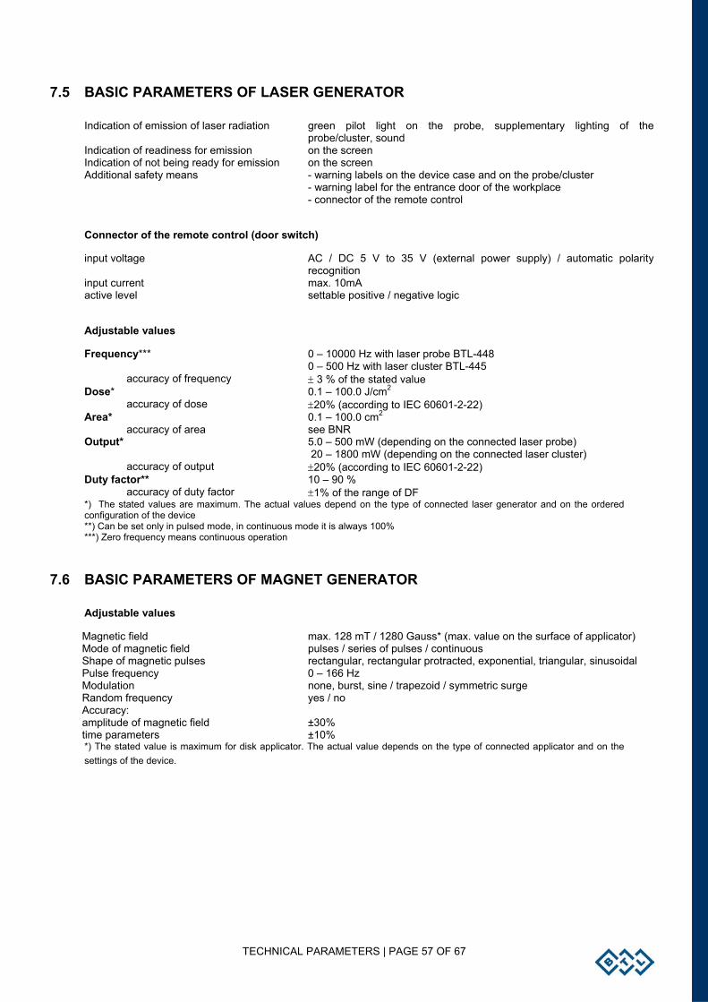
TECHNICAL PARAMETERS | PAGE 57 OF 67
7.5 BASIC PARAMETERS OF LASER GENERATOR
Indication of emission of laser radiation green pilot light on the probe, supplementary lighting of the probe/cluster, sound
Indication of readiness for emission on the screen Indication of not being ready for emission on the screen Additional safety means - warning labels on the device case and on the probe/cluster - warning label for the entrance door of the workplace - connector of the remote control
Connector of the remote control (door switch)
input voltage AC / DC 5 V to 35 V (external power supply) / automatic polarity recognition
input current max. 10mA active level settable positive / negative logic
Adjustable values
Frequency*** 0 – 10000 Hz with laser probe BTL-448 0 – 500 Hz with laser cluster BTL-445
accuracy of frequency ± 3 % of the stated value Dose* 0.1 – 100.0 J/cm2
accuracy of dose ±20% (according to IEC 60601-2-22) Area* 0.1 – 100.0 cm2
accuracy of area see BNR Output* 5.0 – 500 mW (depending on the connected laser probe)
20 – 1800 mW (depending on the connected laser cluster) accuracy of output ±20% (according to IEC 60601-2-22)
Duty factor** 10 – 90 % accuracy of duty factor ±1% of the range of DF
*) The stated values are maximum. The actual values depend on the type of connected laser generator and on the ordered configuration of the device **) Can be set only in pulsed mode, in continuous mode it is always 100% ***) Zero frequency means continuous operation
7.6 BASIC PARAMETERS OF MAGNET GENERATOR
Adjustable values
Magnetic field max. 128 mT / 1280 Gauss* (max. value on the surface of applicator) Mode of magnetic field pulses / series of pulses / continuous Shape of magnetic pulses rectangular, rectangular protracted, exponential, triangular, sinusoidal Pulse frequency 0 – 166 Hz Modulation none, burst, sine / trapezoid / symmetric surge Random frequency yes / no Accuracy: amplitude of magnetic field ±30% time parameters ±10% *) The stated value is maximum for disk applicator. The actual value depends on the type of connected applicator and on the settings of the device.
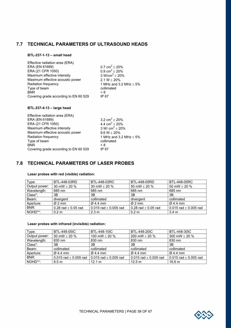
TECHNICAL PARAMETERS | PAGE 58 OF 67
7.7 TECHNICAL PARAMETERS OF ULTRASOUND HEADS
BTL-237-1-13 – small head
Effective radiation area (ERA) ERA (EN 61689) 0.7 cm2 ± 20% ERA (21 CFR 1050) 0.9 cm2 ± 20% Maximum effective intensity 3 W/cm2 ± 20% Maximum effective acoustic power 2.1 W ± 20% Radiation frequency 1 MHz and 3.2 MHz ± 5% Type of beam collimated BNR < 8 Covering grade according to EN 60 529 IP 67
BTL-237-4-13 – large head
Effective radiation area (ERA) ERA (EN 61689) 3.2 cm2 ± 20% ERA (21 CFR 1050) 4.4 cm2 ± 20% Maximum effective intensity 3 W/ cm2 ± 20% Maximum effective acoustic power 9.6 W ± 20% Radiation frequency 1 MHz and 3.2 MHz ± 5% Type of beam collimated BNR < 8 Covering grade according to EN 60 529 IP 67
7.8 TECHNICAL PARAMETERS OF LASER PROBES
Laser probes with red (visible) radiation:
Type: BTL-448-03RD BTL-448-03RC BTL-448-05RD BTL-448-05RC Output power: 30 mW ± 20 % 30 mW ± 20 % 50 mW ± 20 % 50 mW ± 20 % Wavelength: 685 nm 685 nm 685 nm 685 nm Class*: 3B 3B 3B 3B Beam: divergent collimated divergent collimated Aperture: Ø 2 mm Ø 4.4 mm Ø 2 mm Ø 4.4 mm BNR: 0.28 rad ± 0.05 rad 0.015 rad ± 0.005 rad 0.28 rad ± 0.05 rad 0.015 rad ± 0.005 rad NOHD**: 0.2 m 2.3 m 0.2 m 3.4 m
Laser probes with infrared (invisible) radiation:
Type: BTL-448-05IC BTL-448-10IC BTL-448-20IC BTL-448-30IC Output power: 50 mW ± 20 % 100 mW ± 20 % 200 mW ± 20 % 300 mW ± 20 % Wavelength: 830 nm 830 nm 830 nm 830 nm Class*: 3B 3B 3B 3B Beam: collimated collimated collimated collimated Aperture: Ø 4.4 mm Ø 4.4 mm Ø 4.4 mm Ø 4.4 mm BNR: 0.015 rad ± 0.005 rad 0.015 rad ± 0.005 rad 0.015 rad ± 0.005 rad 0.015 rad ± 0.005 rad NOHD**: 8.5 m 12.1 m 12.5 m 16.6 m
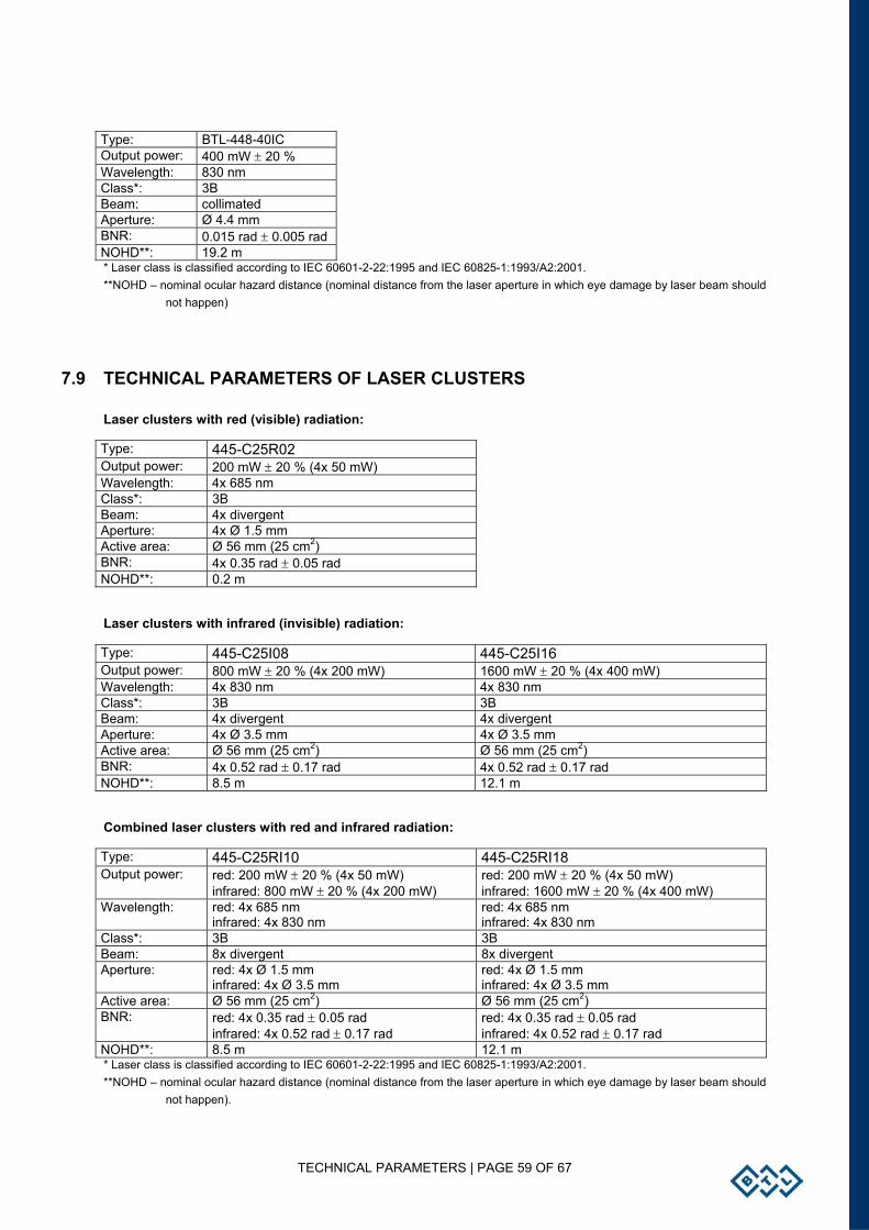
TECHNICAL PARAMETERS | PAGE 59 OF 67
Type: BTL-448-40IC Output power: 400 mW ± 20 % Wavelength: 830 nm Class*: 3B Beam: collimated Aperture: Ø 4.4 mm BNR: 0.015 rad ± 0.005 rad NOHD**: 19.2 m * Laser class is classified according to IEC 60601-2-22:1995 and IEC 60825-1:1993/A2:2001. **NOHD – nominal ocular hazard distance (nominal distance from the laser aperture in which eye damage by laser beam should
not happen)
7.9 TECHNICAL PARAMETERS OF LASER CLUSTERS
Laser clusters with red (visible) radiation:
Type: 445-C25R02 Output power: 200 mW ± 20 % (4x 50 mW) Wavelength: 4x 685 nm Class*: 3B Beam: 4x divergent Aperture: 4x Ø 1.5 mm Active area: Ø 56 mm (25 cm2) BNR: 4x 0.35 rad ± 0.05 rad NOHD**: 0.2 m
Laser clusters with infrared (invisible) radiation:
Type: 445-C25I08 445-C25I16 Output power: 800 mW ± 20 % (4x 200 mW) 1600 mW ± 20 % (4x 400 mW) Wavelength: 4x 830 nm 4x 830 nm Class*: 3B 3B Beam: 4x divergent 4x divergent Aperture: 4x Ø 3.5 mm 4x Ø 3.5 mm Active area: Ø 56 mm (25 cm2) Ø 56 mm (25 cm2) BNR: 4x 0.52 rad ± 0.17 rad 4x 0.52 rad ± 0.17 rad NOHD**: 8.5 m 12.1 m
Combined laser clusters with red and infrared radiation:
Type: 445-C25RI10 445-C25RI18 Output power: red: 200 mW ± 20 % (4x 50 mW)
infrared: 800 mW ± 20 % (4x 200 mW) red: 200 mW ± 20 % (4x 50 mW) infrared: 1600 mW ± 20 % (4x 400 mW)
Wavelength: red: 4x 685 nm infrared: 4x 830 nm
red: 4x 685 nm infrared: 4x 830 nm
Class*: 3B 3B Beam: 8x divergent 8x divergent Aperture: red: 4x Ø 1.5 mm
infrared: 4x Ø 3.5 mm red: 4x Ø 1.5 mm infrared: 4x Ø 3.5 mm
Active area: Ø 56 mm (25 cm2) Ø 56 mm (25 cm2) BNR: red: 4x 0.35 rad ± 0.05 rad
infrared: 4x 0.52 rad ± 0.17 rad red: 4x 0.35 rad ± 0.05 rad infrared: 4x 0.52 rad ± 0.17 rad
NOHD**: 8.5 m 12.1 m * Laser class is classified according to IEC 60601-2-22:1995 and IEC 60825-1:1993/A2:2001. **NOHD – nominal ocular hazard distance (nominal distance from the laser aperture in which eye damage by laser beam should
not happen).
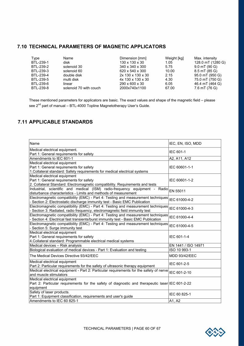
TECHNICAL PARAMETERS | PAGE 60 OF 67
7.10 TECHNICAL PARAMETERS OF MAGNETIC APPLICATORS
Type Name Dimension [mm] Weight [kg] Max. intensity BTL-239-1 disk 130 x 130 x 30 1.05 128.0 mT (1280 G) BTL-239-2 solenoid 30 340 x 340 x 300 5.75 9.0 mT (90 G) BTL-239-3 solenoid 60 620 x 540 x 300 10.00 8.5 mT (85 G) BTL-239-4 double disk 2x 130 x 130 x 30 2.15 95.0 mT (950 G) BTL-239-5 multi disk 4x 130 x 130 x 30 4.30 75.0 mT (750 G) BTL-239-6 linear 290 x 600 x 30 6.05 46.4 mT (464 G) BTL-239-8 solenoid 70 with couch 2000x740x1100 67.00 7.6 mT (76 G)
These mentioned parameters for applicators are basic. The exact values and shape of the magnetic field – please see 2nd part of manual – BTL-4000 Topline Magnetotherapy User’s Guide.
7.11 APPLICABLE STANDARDS
Name IEC, EN, ISO, MDD
Medical electrical equipment. Part 1: General requirements for safety IEC 601-1
Amendments to IEC 601-1 A2, A11, A12 Medical electrical equipment Part 1: General requirements for safety 1.Collateral standard: Safety requirements for medical electrical systems
IEC 60601-1-1
Medical electrical equipment Part 1: General requirements for safety 2. Collateral Standard: Electromagnetic compatibility. Requirements and tests
IEC 60601-1-2
Industrial, scientific and medical (ISM) radio-frequency equipment - Radio disturbance characteristics - Limits and methods of measurement EN 55011
Electromagnetic compatibility (EMC) - Part 4: Testing and measurement techniques - Section 2: Electrostatic discharge immunity test - Basic EMC Publication IEC 61000-4-2
Electromagnetic compatibility (EMC) - Part 4: Testing and measurement techniques - Section 3: Radiated, radio frequency, electromagnetic field immunity test IEC 61000-4-3
Electromagnetic compatibility (EMC) - Part 4: Testing and measurement techniques - Section 4: Electrical fast transients/burst immunity test - Basic EMC Publication IEC 61000-4-4
Electromagnetic compatibility (EMC) - Part 4: Testing and measurement techniques - Section 5: Surge immunity test IEC 61000-4-5
Medical electrical equipment Part 1: General requirements for safety 4.Collateral standard: Programmable electrical medical systems
IEC 601-1-4
Medical devices – Risk analysis EN 1441 / ISO 14971 Biological evaluation of medical devices - Part 1: Evaluation and testing ISO 10 993-1 The Medical Devices Directive 93/42/EEC MDD 93/42/EEC Medical electrical equipment Part 2: Particular requirements for the safety of ultrasonic therapy equipment IEC 601-2-5
Medical electrical equipment - Part 2: Particular requirements for the safety of nerve and muscle stimulators IEC 601-2-10
Medical electrical equipment Part 2: Particular requirements for the safety of diagnostic and therapeutic laser equipment
IEC 601-2-22
Safety of laser products. Part 1: Equipment classification, requirements and user's guide IEC 60 825-1
Amendments to IEC 60 825-1 A1, A2
TECHNICAL PARAMETERS | PAGE 61 OF 67
7.12 INTERCONNECTION OF DEVICES
BTL-4000 Topline Puls can be interconnected with: BTL vac, BTL-4000 Topline Sono, BTL-12, BTL-07p, BTL-4000 Sono, BTL-5000 Sono
BTL-4000 Topline Combi can be interconnected with: BTL vac, BTL-12
BTL-4000 Topline Sono can be interconnected with: BTL-4000 Topline Puls, BTL-4000 Puls, BTL-5000 Sono
Other combinations are not allowed.
7.13 MANUFACTURER
This product is manufactured in accordance with the EU Medical Devices Directive by:
BTL Industries Ltd. 161 Cleveland Way Stevenage Hertfordshire SG1 6BU United Kingdom E-mail: [email protected] http://www.btlnet.com
For service, please contact the service department at [email protected].
© All rights reserved. No part of this manual may be reproduced, saved in a research centre or transferred by any means incl. electronic, mechanical, photographic or other records without previous approval from BTL Industries Limited
BTL Industries Limited operates a policy of continuous development. Therefore, it reserves the right to make changes and improvements to the Product described in this manual without prior notice.
The contents of this document are provided "as is". Except as required by the applicable law, no warranties of any kind, either expressed or implied, are made in relation to the accuracy, reliability or contents of this document. BTL Industries Limited reserves the right to revise this document or withdraw it at any time without prior notice.
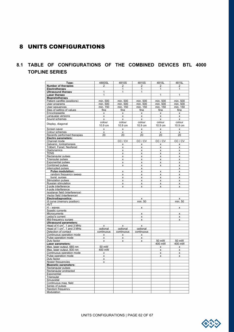
UNITS CONFIGURATIONS | PAGE 62 OF 67
8 UNITS CONFIGURATIONS
8.1 TABLE OF CONFIGURATIONS OF THE COMBINED DEVICES BTL 4000 TOPLINE SERIES
Type: 4800SL 4810S 4815S 4810L 4815L Number of therapies 2 2 2 2 2 Electrotherapy 1 1 1 1 Ultrasound therapy 1 1 1 Laser therapy 1 1 1 Magnetotherapy Patient cardfile (positions) min. 500 min. 500 min. 500 min. 500 min. 500 User programs min. 500 min. 500 min. 500 min. 500 min. 500 User sequences min. 150 min. 150 min. 150 min. 150 min. 150 Step of setting of values fine fine fine fine fine Encyclopaedia x x x x x Language versions x x x x x Sound schemes x x x x x
Display, diagonal colour 10.9 cm
colour 10.9 cm
colour 10.9 cm
colour 10.9 cm
colour 10.9 cm
Screen saver x x x x x Colour schemes x x x x x Recently performed therapies 20 20 20 20 20 Electro parameters: Channel mode CC / CV CC / CV CC / CV CC / CV Galvanic, Iontophoresis x x x x Träbert, Farad, Neofarad x x x x Diadynamics x x x x TENS x x x x Rectangular pulses x x x x Triangular pulses x x x x Exponential pulses x x x x Combined pulses x x x x Interrupted pulses x x Pulse modulation: x x x x random frequency sweep x x x x burst, surges x x x x Stimulation pulses x x x x Russian stimulation x x x x 2-pole interference x x x x 4-pole interference Isoplanar field (interference) Vector field (interference) Electrodiagnostics: x x I/t curve (memory position) min. 50 min. 50 HVT H – waves x x Spastic currents Microcurrents x x Leduc's current x x Mid-frequency surges x x Ultrasound parameters: Head of 4 cm2, 1 and 3 MHz x x x Head of 1 cm2, 1 and 3 MHz optional optional optional Detection of contact continuous continuous continuous Continuous operation mode x x x Pulse operation mode x x x Duty factor x x x 50 mW 50 mW Laser parameters: 400 mW 400 mW Max. laser output, 685 nm 50 mW x x Max. laser output, 830 nm 400 mW x x Continuous operation mode x x x Pulse operation mode x x x Duty factor x Nogier frequencies x Magnetic parameters: Rectangular pulses Rectangular protracted Exponential Triangular Sinusoidal Continuous mag. field Series of pulses Random frequency Modulation
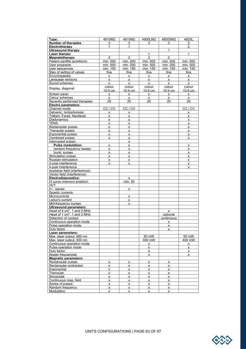
UNITS CONFIGURATIONS | PAGE 63 OF 67
Type: 4810M2 4815M2 4800LM2 4800SM2 4820L Number of therapies 3 3 3 3 3 Electrotherapy 1 1 2 Ultrasound therapy 1 Laser therapy 1 1 Magnetotherapy 2 2 2 2 Patient cardfile (positions) min. 500 min. 500 min. 500 min. 500 min. 500 User programs min. 500 min. 500 min. 500 min. 500 min. 500 User sequences min. 150 min. 150 min. 150 min. 150 min. 150 Step of setting of values fine fine fine fine fine Encyclopaedia x x x x x Language versions x x x x x Sound schemes x x x x x Display, diagonal colour
10.9 cmcolour
10.9 cmcolour
10.9 cmcolour
10.9 cm colour
10.9 cm Screen saver x x x x x Colour schemes x x x x x Recently performed therapies 20 20 20 20 20 Electro parameters: Channel mode CC / CV CC / CV CC / CV Galvanic, Iontophoresis x x x Träbert, Farad, Neofarad x x x Diadynamics x x x TENS x x x Rectangular pulses x x x Triangular pulses x x x Exponential pulses x x x Combined pulses x x x Interrupted pulses x Pulse modulation: x x x random frequency sweep x x x burst, surges x x x Stimulation pulses x x x Russian stimulation x x x 2-pole interference x x x 4-pole interference x Isoplanar field (interference) Vector field (interference) Electrodiagnostics: x I/t curve (memory position) min. 50 HVT H – waves x Spastic currents Microcurrents x Leduc's current x Mid-frequency surges x Ultrasound parameters: Head of 4 cm2, 1 and 3 MHz x Head of 1 cm2, 1 and 3 MHz optional Detection of contact continuous Continuous operation mode x Pulse operation mode x Duty factor x Laser parameters: Max. laser output, 685 nm 50 mW 50 mW Max. laser output, 830 nm 400 mW 400 mW Continuous operation mode x x Pulse operation mode x x Duty factor x x Nogier frequencies x x Magnetic parameters: Rectangular pulses x x x x Rectangular protracted x x x x Exponential x x x x Triangular x x x x Sinusoidal x x x x Continuous mag. field x x x x Series of pulses x x x x Random frequency x x x x Modulation x x x x
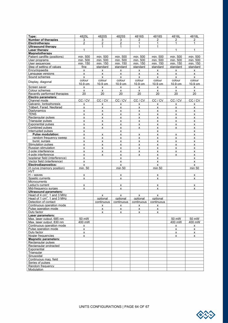
UNITS CONFIGURATIONS | PAGE 64 OF 67
Type: 4825L 4820S 4825S 4816S 4818S 4816L 4818LNumber of therapies 3 3 3 2 2 2 2Electrotherapy 2 2 2 1 1 1 1Ultrasound therapy 1 1 1 1 Laser therapy 1 1 1Magnetotherapy Patient cardfile (positions) min. 500 min. 500 min. 500 min. 500 min. 500 min. 500 min. 500User programs min. 500 min. 500 min. 500 min. 500 min. 500 min. 500 min. 500User sequences min. 150 min. 150 min. 150 min. 150 min. 150 min. 150 min. 150Step of setting of values fine standard standard standard standard standard standardEncyclopaedia x x x x x x xLanguage versions x x x x x x xSound schemes x x x x x x xDisplay, diagonal colour
10.9 cm colour
10.9 cmcolour
10.9 cmcolour
10.9 cmcolour
10.9 cm colour
10.9 cm colour
10.9 cmScreen saver x x x x x x xColour schemes x x x x x x xRecently performed therapies 20 20 20 20 20 20 20Electro parameters: Channel mode CC / CV CC / CV CC / CV CC / CV CC / CV CC / CV CC / CVGalvanic, Iontophoresis x x x x x x xTräbert, Farad, Neofarad x x x x x x xDiadynamics x x x x x x xTENS x x x x x x xRectangular pulses x x x x x x xTriangular pulses x x x x x x xExponential pulses x x x x x x xCombined pulses x x x x x x xInterrupted pulses x x x x Pulse modulation: x x x x x x x random frequency sweep x x x x x x x burst, surges x x x x x x xStimulation pulses x x x x x x xRussian stimulation x x x x x x x2-pole interference x x x x x x x4-pole interference x x x x x x xIsoplanar field (interference) x x x xVector field (interference) x x x xElectrodiagnostics: x x x xI/t curve (memory position) min. 50 min 50 min 50 min 50HVT H – waves x x x xSpastic currents x x x xMicrocurrents Leduc's current x x x xMid-frequency surges x x x xUltrasound parameters: Head of 4 cm2, 1 and 3 MHz x x x x Head of 1 cm2, 1 and 3 MHz optional optional optional optional Detection of contact continuous continuous continuous continuous Continuous operation mode x x x x Pulse operation mode x x x x Duty factor x x x x Laser parameters: Max. laser output, 685 nm 50 mW 50 mW 50 mWMax. laser output, 830 nm 400 mW 400 mW 400 mWContinuous operation mode x x xPulse operation mode x x xDuty factor x x xNogier frequencies x x xMagnetic parameters: Rectangular pulses Rectangular protracted Exponential Triangular Sinusoidal Continuous mag. field Series of pulses Random frequency Modulation
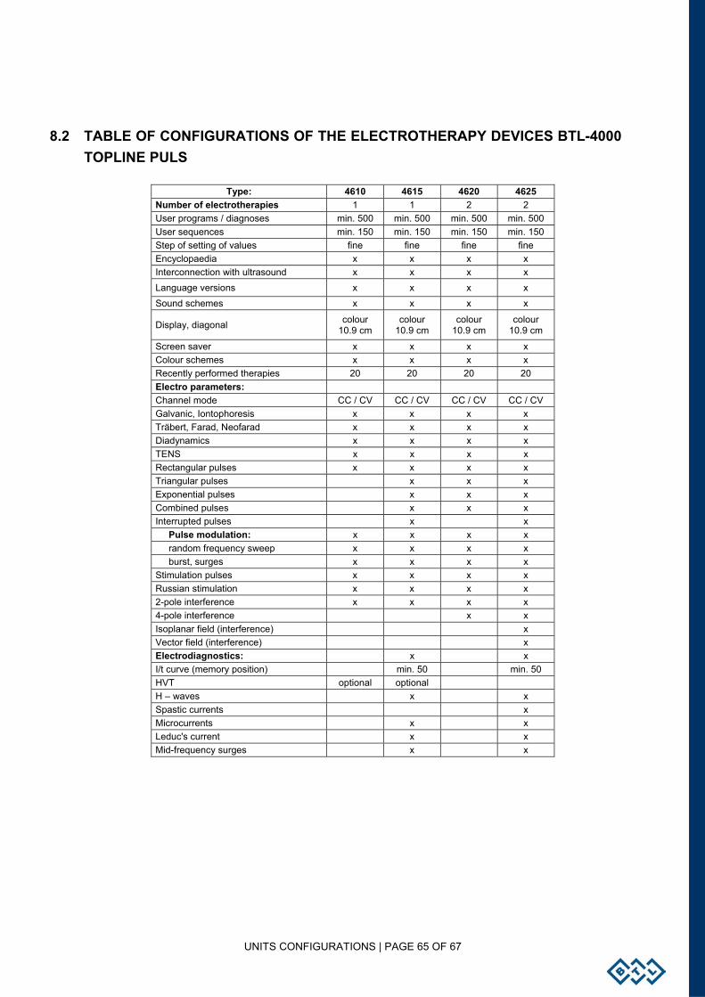
UNITS CONFIGURATIONS | PAGE 65 OF 67
8.2 TABLE OF CONFIGURATIONS OF THE ELECTROTHERAPY DEVICES BTL-4000 TOPLINE PULS
Type: 4610 4615 4620 4625 Number of electrotherapies 1 1 2 2 User programs / diagnoses min. 500 min. 500 min. 500 min. 500 User sequences min. 150 min. 150 min. 150 min. 150 Step of setting of values fine fine fine fine Encyclopaedia x x x x Interconnection with ultrasound x x x x Language versions x x x x Sound schemes x x x x
Display, diagonal colour 10.9 cm
colour 10.9 cm
colour 10.9 cm
colour 10.9 cm
Screen saver x x x x Colour schemes x x x x Recently performed therapies 20 20 20 20 Electro parameters: Channel mode CC / CV CC / CV CC / CV CC / CV Galvanic, Iontophoresis x x x x Träbert, Farad, Neofarad x x x x Diadynamics x x x x TENS x x x x Rectangular pulses x x x x Triangular pulses x x x Exponential pulses x x x Combined pulses x x x Interrupted pulses x x Pulse modulation: x x x x random frequency sweep x x x x burst, surges x x x x Stimulation pulses x x x x Russian stimulation x x x x 2-pole interference x x x x 4-pole interference x x Isoplanar field (interference) x Vector field (interference) x Electrodiagnostics: x x I/t curve (memory position) min. 50 min. 50 HVT optional optional H – waves x x Spastic currents x Microcurrents x x Leduc's current x x Mid-frequency surges x x
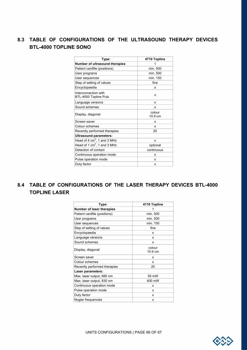
UNITS CONFIGURATIONS | PAGE 66 OF 67
8.3 TABLE OF CONFIGURATIONS OF THE ULTRASOUND THERAPY DEVICES BTL-4000 TOPLINE SONO
Type: 4710 Topline Number of ultrasound therapies 1 Patient cardfile (positions) min. 500 User programs min. 500 User sequences min. 150 Step of setting of values fine Encyclopaedia x
Interconnection with BTL-4000 Topline Puls x
Language versions x Sound schemes x
Display, diagonal colour 10.9 cm
Screen saver x Colour schemes x Recently performed therapies 20 Ultrasound parameters: Head of 4 cm2, 1 and 3 MHz x Head of 1 cm2, 1 and 3 MHz optional Detection of contact continuous Continuous operation mode x Pulse operation mode x Duty factor x
8.4 TABLE OF CONFIGURATIONS OF THE LASER THERAPY DEVICES BTL-4000 TOPLINE LASER
Type: 4110 Topline Number of laser therapies 1 Patient cardfile (positions) min. 500 User programs min. 500 User sequences min. 150 Step of setting of values fine Encyclopaedia x Language versions x Sound schemes x
Display, diagonal colour 10.9 cm
Screen saver x Colour schemes x Recently performed therapies 20 Laser parameters: Max. laser output, 685 nm 50 mW Max. laser output, 830 nm 400 mW Continuous operation mode x Pulse operation mode x Duty factor x Nogier frequencies x
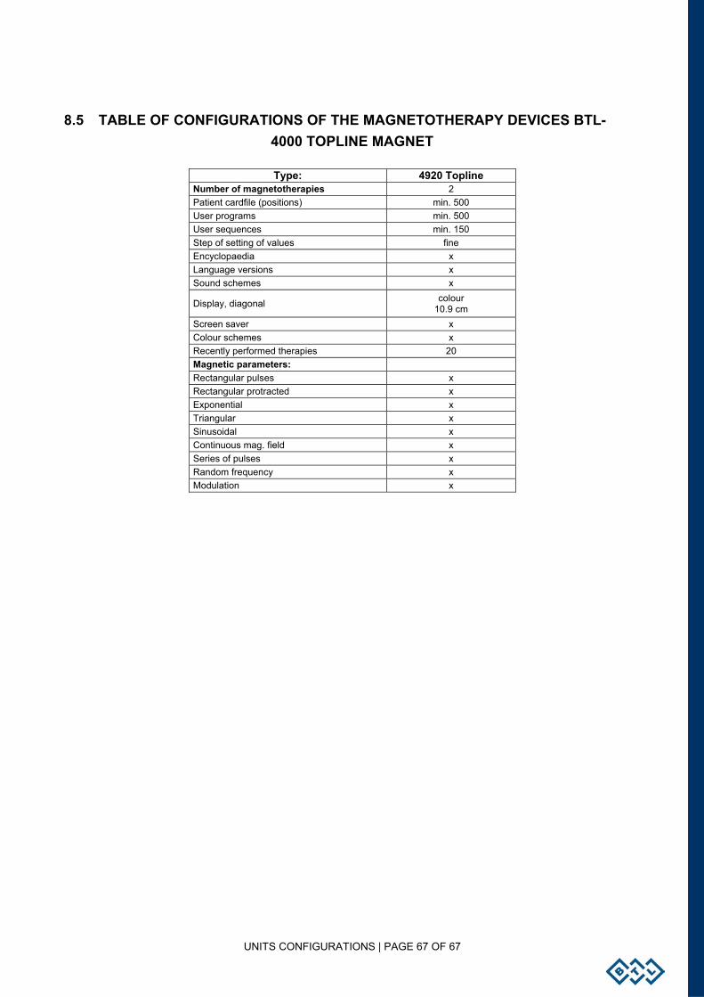
UNITS CONFIGURATIONS | PAGE 67 OF 67
8.5 TABLE OF CONFIGURATIONS OF THE MAGNETOTHERAPY DEVICES BTL-4000 TOPLINE MAGNET
Type: 4920 Topline Number of magnetotherapies 2 Patient cardfile (positions) min. 500 User programs min. 500 User sequences min. 150 Step of setting of values fine Encyclopaedia x Language versions x Sound schemes x
Display, diagonal colour 10.9 cm
Screen saver x Colour schemes x Recently performed therapies 20 Magnetic parameters: Rectangular pulses x Rectangular protracted x Exponential x Triangular x Sinusoidal x Continuous mag. field x Series of pulses x Random frequency x Modulation x