Embed Size (px)
Citation preview
GENERAL CHARACTERISTICS OF THE DEVICE | PAGE 1 OF 38
BTL-6000 SWT TOPLINE USER’S MANUAL
v100AS08/01/2010EN
PAGE 2 OF 38
BEFORE YOU START
Dear Customer,
Thank you for purchasing BTL technology. All of us at BTL wish
you every success with your system. We pride ourselves on being
as responsive as possible to our customers’ needs. Your
suggestions and comments are always welcome since we believe
an ongoing relationship with our customers is critically important to
our future product line.
While we would like you to start using your new equipment right
away, we encourage a thorough reading of this manual in order to
fully understand the operational features of the system.
Please visit our corporate website at http://www.btlnet.com for the
latest information on BTL products and services.
Again, thank you for being a BTL customer.
BTL Industries, Ltd.

PAGE 3 OF 38
CONTENTS
1 GENERAL CHARACTERISTICS OF THE DEVICE.............. .................................................................................................5
1.1 BTL–6000 SWT Topline System Series..............................................................................................................................5 1.2 Shockwave and Its Character.............................................................................................................................................6 1.3 Shockwave Generation.......................................................................................................................................................6
1.3.1 Ballistic Principle of Shockwave Generation .....................................................................................................................6
1.4 Biological Effects of Shockwave Treatment ........................................................................................................................7 1.5 Advantages of Shockwave Treatment ................................................................................................................................7 1.6 Possible side Effects of Shockwave Treatment...................................................................................................................7 1.7 Indications for Shockwave Treatment .................................................................................................................................8 1.8 Contra-indications for Shockwave Treatment......................................................................................................................8
2 INSTRUCTIONS FOR OPERATION......................................................................................................................................9
2.1 The Front Panel of the BTL-6000 SWT Topline ..................................................................................................................9 2.2 Applicator for BTL-6000 SWT Topline ................................................................................................................................9 2.3 The Rear Panel of the BTL-6000 SWT Topline.................................................................................................................10 2.4 Assembly and Set-Up.......................................................................................................................................................11 2.5 Basic Displays and Operating of the Device .....................................................................................................................12
2.5.1 Initial Screen and Types of Tabs ....................................................................................................................................12 2.5.2 Touch Screen.................................................................................................................................................................12 2.5.3 Numeric Keypad ............................................................................................................................................................13
2.6 Setting of Therapy ............................................................................................................................................................13
2.6.1 Setting Therapy Parameters Via the ‘diag’ Button ..........................................................................................................13 2.6.2 Setting Therapy Parameters Via the 'prog' Button ..........................................................................................................13 2.6.3 Setting Therapy Parameters Manually (User Setup) Via the ‘man' Button ......................................................................14 2.6.4 Setting the Number of Shocks........................................................................................................................................14 2.6.5 Setting Therapy Intensity................................................................................................................................................15 2.6.6 Therapy Parameters Screen – Ergonomic, Standard and Expert Mode..........................................................................16
2.7 Course of Therapy............................................................................................................................................................16
2.7.1 Start, Interruption and End of Therapy............................................................................................................................16 2.7.2 Running Therapy Screen ...............................................................................................................................................17 2.7.3 End of Therapy / Generation of Shocks..........................................................................................................................17
2.8 Application of Shockwaves ...............................................................................................................................................17 2.9 Saving Therapy ................................................................................................................................................................19 2.10 User Settings: The ‘user’ Button .......................................................................................................................................19
2.10.1 Clients............................................................................................................................................................................20 2.10.2 User Diagnoses/Programs .............................................................................................................................................20 2.10.3 Recent Therapies...........................................................................................................................................................20
2.11 Unit Settings: The ‘menu’ Button ......................................................................................................................................20
2.11.1 Accessories....................................................................................................................................................................20
2.11.1.1 Installation ..............................................................................................................................................................20 2.11.1.2 Information..............................................................................................................................................................21 2.11.2 Encyclopaedia................................................................................................................................................................21 2.11.3 Unit Settings...................................................................................................................................................................22
2.11.3.1 Password Setting....................................................................................................................................................22 2.11.3.2 Sound Setting .........................................................................................................................................................22 2.11.3.3 Screen Saver and Auto Switch-Off..........................................................................................................................22 2.11.3.4 Colour Setting.........................................................................................................................................................22 2.11.3.5 Setting of Display Contrast......................................................................................................................................23 2.11.3.6 Date and Time Setting ............................................................................................................................................23 2.11.3.7 Language Setting....................................................................................................................................................23
PAGE 4 OF 38
2.11.3.8 Operation Mode......................................................................................................................................................23 2.11.3.9 Touch Panel Calibration..........................................................................................................................................23 2.11.3.10 User Options...........................................................................................................................................................23 2.11.3.11 Setting of HW Key ..................................................................................................................................................23 2.11.3.12 Unit Information ......................................................................................................................................................23 2.11.3.13 Unlock Code ...........................................................................................................................................................23 2.11.3.14 Service Functions ...................................................................................................................................................24 2.11.4 Specific Settings ............................................................................................................................................................24
2.11.4.1 Applicator Button Mode...........................................................................................................................................24 2.11.4.2 Applicator Kit Replacement Wizard .........................................................................................................................24 3 LIST OF STANDARD AND OPTIONAL ACCESSORIES.......... ..........................................................................................25
4 MAINTENANCE AND SAFETY INSTRUCTIONS................ ................................................................................................26
4.1.1 Shock Transmitter Replacement Procedure ...................................................................................................................27 4.1.2 Procedure of Worn-out Tube and Projectile Replacement ..............................................................................................28
4.2 General Safety Precautions..............................................................................................................................................31 4.3 Used Symbols ..................................................................................................................................................................32 4.4 Warranty...........................................................................................................................................................................32
5 TECHNICAL PARAMETERS ............................... ...............................................................................................................33
5.1 EMC Information ..............................................................................................................................................................35 5.2 Applicable Standards........................................................................................................................................................37 5.3 Manufacturer ....................................................................................................................................................................38
GENERAL CHARACTERISTICS OF THE DEVICE | PAGE 5 OF 38
1 GENERAL CHARACTERISTICS OF THE DEVICE
The BTL-6000 SWT Topline is a state-of-the-art device allowing the application of therapy using non-invasive shockwaves.
Shockwaves are one of the most effective ways to treat pain associated with the musculoskeletal system. Musculoskeletal pain
is currently the second-leading cause of absences in the workplace.
The device is equipped with a color touch screen on the main unit which considerably simplifies its use. The touch screen is
equipped with a stylus (touch-pen) for easy operation of the device. The horizontally orientation of the device allows the
information on the screen to be seen clearly from different servicing positions. Additionally, the brightness of the screen can be
set to match the lighting in the room of the office or the health-care center. The on-screen information will guide the user step-
by-step through the entire therapy process. The therapeutic parameters are easily set using the touch screen buttons and
knobs/keys on the device.
Therapy is easily and efficiently started by simply selecting a diagnosis from an alphabetized list of treatment protocols or by
selecting a therapy program. The treatment parameters can be manually set by the simple use of the touch screen buttons.
Throughout the course of a therapy session, the device will keep the user informed about the therapeutic method in use, the
type of treatment, the total number of shocks to be applied, the number of shocks applied and remaining, the frequency being
used, the intensity and other necessary data.
A time-saving feature of the BTL-6000 SWT Topline is the predefined programs stored in the memory of the main unit. Based on
detailed research and practical use of the device, the well-organized predefined programs will provide recommendations for the
treatment of various conditions.
The BTL-6000 SWT Topline allows the entering of client names and other relevant information into the internal memory of the
device and to link their data with the predefined programs or with the user’s own. When a client has a return visit, simply call up
their name and begin the pre-set therapy.
We also carry a specially-designed cart for the BTL-6000 SWT Topline which is sold separately. The design allows convenient
movement and use of the device. Four stable castors ensure smooth and easy movement of the device in the office or the
health-care center.
For the latest information on BTL products and services, please visit our corporate website at http://www.btlnet.com.
1.1 BTL–6000 SWT TOPLINE SYSTEM SERIES
The device consists of two parts: the main unit and the applicator
Main Unit: BTL-6000 SWT Topline which contains the main microcomputer and software for controlling the entire system,in
also includes the user encyclopaedia and the therapy guide.
Applicator – ergonomical applicator simplifies the „course of" the therapy, following the instructions of the main unit.
The BTL-6000 SWT Topline is a state-of-the-art device allowing the application of therapy using non-invasive shockwaves.
Shockwaves are one of the most effective ways to treat pain associated with the musculoskeletal system. Musculoskeletal pain
is currently the second-leading cause of absences in the workplace.
The device consists of two parts:
• Main Unit – contains the main microcomputer and software for controlling the entire system
• Applicator – this ergonomically designed applicator will simplify the course of therapy
GENERAL CHARACTERISTICS OF THE DEVICE | PAGE 6 OF 38
1.2 SHOCKWAVE AND ITS CHARACTER
A shockwave is defined as a wave with a rapid increase of pressure within a very short time and then having a gradual decrease
of pressure with a small negative pressure phase.
Shockwaves are aimed at the affected areas that are the source of chronic pain. The influence of the shockwaves causes to the
dissolution of calcium deposits and leads to better vascularization. The after-effect is relief from the pain.
Outside of the client's body (extra-corporeally), a pressure pulse of high amplitude is generated and its energy is concentrated
on the target area. The pressure pulse travels through a liquid medium gel into the client’s body and penetrates soft tissue
without major energy loss.
The pressure course of the shockwave in real-time in expressively different from the pressure course of the harmonic sound
wave. Shockwaves can be compared to ultrasonic waves which are particularly characterized by a pressure jump change, a
higher amplitude and non-periodicity.
In the shockwave, the positive amplitude is generally much larger than the negative amplitude. The frequency rate of the
shockwaves is usually low (in Hz units) and the eventual cavitation (the disturbance of material consistency and the
development of cavities) will relax. Consequently, there is no threat of energy absorption in the cavitations as is the case with
continuous ultrasound.
A substantial part of the shockwave energy penetrates into the liquid (of the organism) with a great positive pressure pulse. Its
diffusion is only limited by the actual tissue absorption and eventual reflections on acoustic non-homogeneities.
A shockwave is defined as a pressure pulse with these characteristics:
• High positive pressure amplitude: 10 to 1000 MPa = 100 to 1000 Bar (100x atmospheric pressure)
• Low negative pressure amplitude: 1 to 10 MPa
• Short time duration: 1 µs to 20 µs
• Rapid pressure increase: < 100 ns
• Broad frequency spectrum: 1 Hz to 1 MHz
For therapeutic applications, these values are lower, especially the maximum pressure amplitude. The maximum pressure
amplitude is about 15 MPa, the pulse length is 10 to 20 µs, and the frequency of the applied shockwave is 1 to 15Hz. The
treatment is generally carried out without local anaesthesia and lasts about 15 to 30 minutes. During the first week after
treatment, the client should avoid all physical activities that could excessively strain the treated area.
1.3 SHOCKWAVE GENERATION
Several types of generators have been developed for shockwave therapy, each producing shockwaves with varied
characteristics. Each type of generation method induces shockwaves with different time progressions and spatial arrangements.
The BTL-6000 SWT Topline uses the ballistic principle of shockwave generation.
1.3.1 BALLISTIC PRINCIPLE OF SHOCKWAVE GENERATION
A pressure wave is formed via a projectile by using accelerated compressed air. The compressed air is generated by an
electronically-controlled ballistic-pressure compressor. Using elastic impact, the kinetic energy of the projectile is transferred into
the probe of the applicator and then into the client's body. Consequently, during the treatment, the end of the applicator must be
in direct -contact with the skin and subcutaneous tissue.
GENERAL CHARACTERISTICS OF THE DEVICE | PAGE 7 OF 38
1.4 BIOLOGICAL EFFECTS OF SHOCKWAVE TREATMENT
The effects of the shockwaves mainly occur at sites where there is a change in impedance, such as the bone-soft tissue
interface.
There is an improvement in the regeneration and repair of tissues in the following areas and the achievement of the following
effects:
• Cellular: Increase in cell membrane transmittance by improving ionic channels activity, stimulation of cell division,
stimulation of cellular cytokines production.
• Reproduction of vessels in the area of tendons and muscles: Improvement of blood circulation and MTB, increase in
concentration of growth factor beta 1, chemotactic and mitogenic effect on osteoblasts.
• Effect on nitrogen oxide system: Bone healing and re-modelling.
• Improvement of micro-circulation and metabolism
• Dissolution of calcified fibroblasts
• Supports the production of collagen
• Reduction in tissue tension
• Analgesic effect:
o Destruction of afferent nerves and nerve receptors.
o CNS stimulants, sensed as pain, are also inflammation transmitter substances.
o Regression of pain caused by local ischemia.
o Gate control theory of pain.
1.5 ADVANTAGES OF SHOCKWAVE TREATMENT
• By the targeted application of the shockwaves, stress to the surrounding tissues is quite insignificant.
• The body is not burdened by pharmaceuticals, except the short-term effect of local anaesthesia, if used.
• The possibility of preventing the necessity of surgical intervention and its relevant hazards.
• Thanks to ambulatory treatment, work absences are reduced to a minimum. Additionally, training routine absences for
sport athletes is likewise reduced.
• For some indications, such as Tennis Elbow, there is really no other effective treatment.
1.6 POSSIBLE SIDE EFFECTS OF SHOCKWAVE TREATMENT
• Erythema or swelling can temporarily occur in the treated area.
• Loss of bodily sensation or itching can temporarily occur in the treated area
• Hematoma
• Petechiae
• Skin damage after previous corticoid therapy
• Shockwave application can cause undesirable heart activity
GENERAL CHARACTERISTICS OF THE DEVICE | PAGE 8 OF 38
1.7 INDICATIONS FOR SHOCKWAVE TREATMENT
• Plantar Fasciitis
• Achillodynia/Achillobursitis
• Inflammations and calcification of shoulder joint tendons.
• Pain in the groin area.
• Epicondylitis (Tennis and Golf Elbow)
• Apex Patellae Syndrome and Tibial Stress Syndrome.
• Pain in the hip area and/or the iliotibial tract.
• Jumper's Knee (Patellar Tendinitis)
• Pain in the hamstring insertions.
• Pain on the palmar side of the wrist.
• Exostoses of small hand joints from Grade 1 Arthrosis.
• Acupuncture
• Pain trigger-points or painful points in muscles.
1.8 CONTRA-INDICATIONS FOR SHOCKWAVE TREATMENT
• Application to certain tissues: The eyes and the surrounding area, the myocardium, the spinal cord, the gonads, the kidneys and the liver
• Blood disorders, coagulation problems or the use of anticoagulants
• Blood thinning medications (Warfarinization)
• Polypus in the area of treatment
• Pregnancy
• Thrombosis
• Tumor diseases
• Polyneuropathy
• Acute inflammation
• Growing cartilage in children
• Therapy using corticoids
• Inapplicable on areas of the body and organs with possible gas content
• Inapplicable on areas in proximity to large nerve bundles, blood vessels, the spinal cord and the head
INSTRUCTIONS FOR OPERATION | PAGE 9 OF 38
2 INSTRUCTIONS FOR OPERATION
2.1 THE FRONT PANEL OF THE BTL-6000 SWT TOPLINE
1
1010101010101010210101010101010105
7
10101010101010103
10101010101010104
6
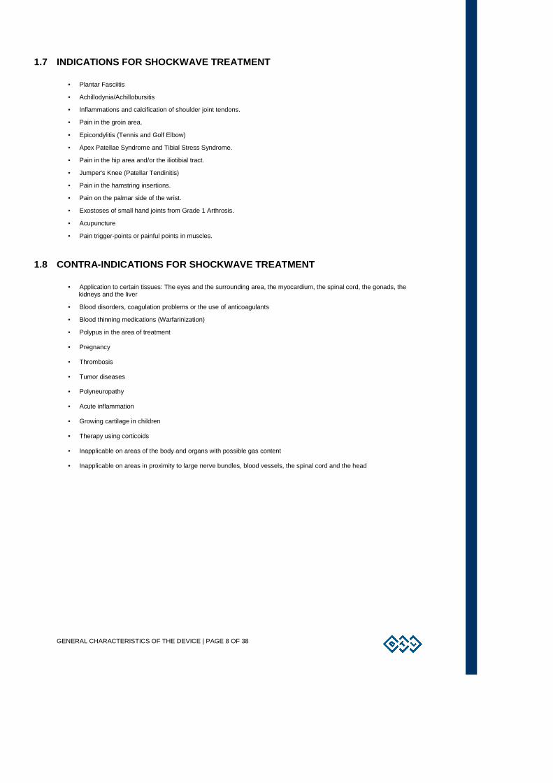
1. touch screen 2. select knob (to select individual parameters) 3. enter key 4. esc key 5. start / stop key (to start and stop therapy) 6. ON/OFF switch (back lit, in blue, when the control unit is ‘’on’’ ) 7. USB port in the space of the device’s grip for use only in compliance with IEC 60950-1 The USB port serves only for service purposes such as upload of firmware; it is not designed for therapy use!
2.2 APPLICATOR FOR BTL-6000 SWT TOPLINE
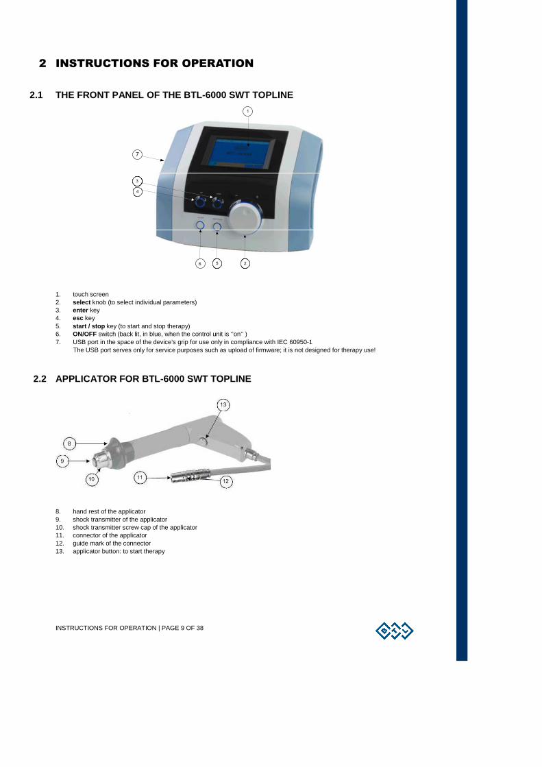
8. hand rest of the applicator 9. shock transmitter of the applicator 10. shock transmitter screw cap of the applicator 11. connector of the applicator 12. guide mark of the connector 13. applicator button: to start therapy
INSTRUCTIONS FOR OPERATION | PAGE 10 OF 38
2.3 THE REAR PANEL OF THE BTL-6000 SWT TOPLINE
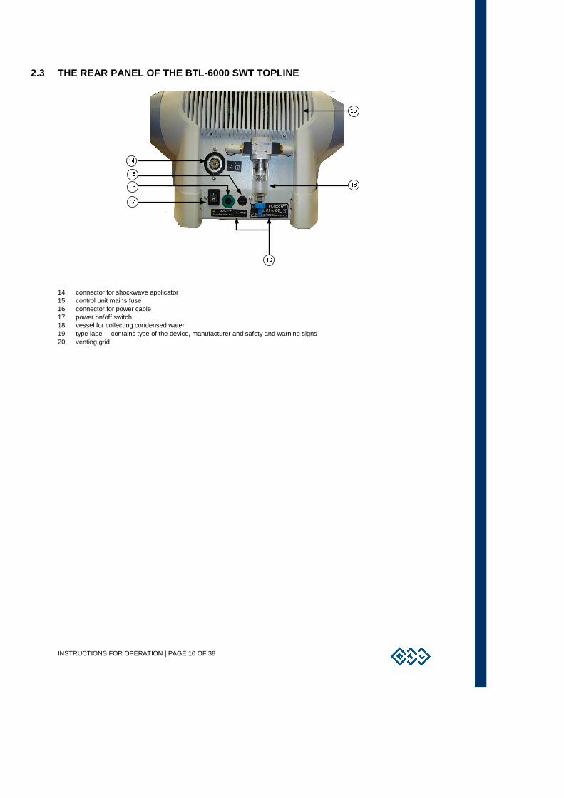
14. connector for shockwave applicator 15. control unit mains fuse 16. connector for power cable 17. power on/off switch 18. vessel for collecting condensed water 19. type label – contains type of the device, manufacturer and safety and warning signs 20. venting grid
INSTRUCTIONS FOR OPERATION | PAGE 11 OF 38
2.4 ASSEMBLY AND SET-UP Inspect the box for damage and report any damage to the transport carrier and the distributor. Do not proceed with assembly
and set-up if the box is damaged. Keep the original box and packaging to ensure safe future transport of the device.
When bringing the device from a cold environment into a warm one, do not plug it into the power source until the device has had
to equilibrate to room temperature (Minimum 2 hours).
Unpack the device and place it on a stable horizontal surface which is suitable for its weight. Always position the device out of
direct sunlight. During operation, the control unit gets warm, so it must not be positioned near direct heat sources. The device is
self-cooled by forced air circulation. The cooling vents are located on the rear panel and on the bottom. Do not cover or block
these vents. Allow a minimum of 4 inches (10cm) clearance behind the rear panel. Do not place the device on a soft surface
(such as a towel) which may obstruct air flow to the bottom cooling vents. Do not put any heat-producing devices or any objects
containing water or other liquids on the device. Do not put any heat-producing devices or objects containing water or other liquid
on the device. Do not place the device close to appliances producing strong electromagnetic, electric or magnetic field
(diathermy, X-rays, etc.), otherwise it could be undesirably influenced.
In the event of any questions, please contact an authorized service of BTL devices.
Procedure:
1. First connect the device in mains by means of the supplied power supply adapter, which you will connect to the connector
on the rear panel of the device and to a 100 V or 240 V mains socket. The device detects the voltage automatically.
Plug the device directly into the mains socket. Do not use any multi-connection extension cables or two-socket adaptors.
2. Connect the applicator to the connector on the rear panel as follows:
Turn the applicator so that the red dot on its end is in straight line with the red dot on the output connector and only then
plug the connector in.
When disconnecting the connector take the indented part of the applicator connector’s end in your fingers and pull slowly
towards you to disconnect the connector carefully.
CAUTION! DO NOT TURN THE ENTIRE CONNECTED CONNECTOR BY FORCE, OTHERWISE THERE IS A RISK OF
DAMAGE TO THE DEVICE!
The device detects the accessory, specifies its type and displays it on the screen in the appropriate tab. If you connect an
improper accessory by mistake, the display shows a message with a help where to connect the given accessory.
3. Then switch on the power on/off switch on the rear panel of the device.
4. Press the on/off switch located on the front panel of the device.
Note:
After switching the device on, the device will run a self-diagnostic of its internal circuits and its functions for about 10 to 15
seconds. If any fault is detected, the screen will display a warning message. If necessary; the control unit will lock itself into a
“secure” mode. If this situation occurs, please contact your authorized BTL distributor.
INSTRUCTIONS FOR OPERATION | PAGE 12 OF 38
2.5 BASIC DISPLAYS AND OPERATING OF THE DEVICE
2.5.1 INITIAL SCREEN AND TYPES OF TABS
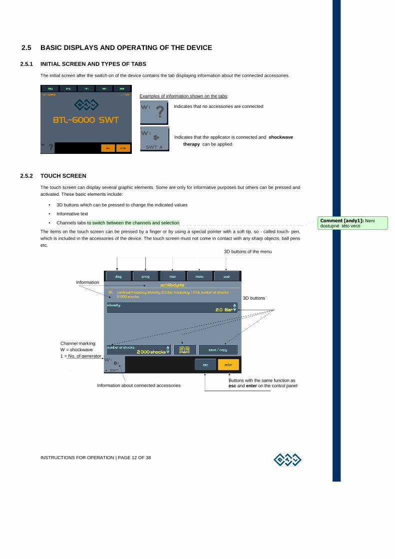
The initial screen after the switch-on of the device contains the tab displaying information about the connected accessories.
Examples of information shown on the tabs:
Indicates that no accessories are connected
Indicates that the applicator is connected and shockwave
therapy can be applied.
2.5.2 TOUCH SCREEN
The touch screen can display several graphic elements. Some are only for informative purposes but others can be pressed and
activated. These basic elements include:
• 3D buttons which can be pressed to change the indicated values
• Informative text
• Channels tabs to switch between the channels and selection
The items on the touch screen can be pressed by a finger or by using a special pointer with a soft tip, so - called touch- pen,
which is included in the accessories of the device. The touch screen must not come in contact with any sharp objects, ball pens
etc.
Information
3D buttons of the menu
Buttons with the same function as esc and enter on the control panel
3D buttons
Channel marking: W = shockwave 1 = No. of generator
Information about connected accessories
Comment [andy1]: Neni dostupné této verzi
INSTRUCTIONS FOR OPERATION | PAGE 13 OF 38
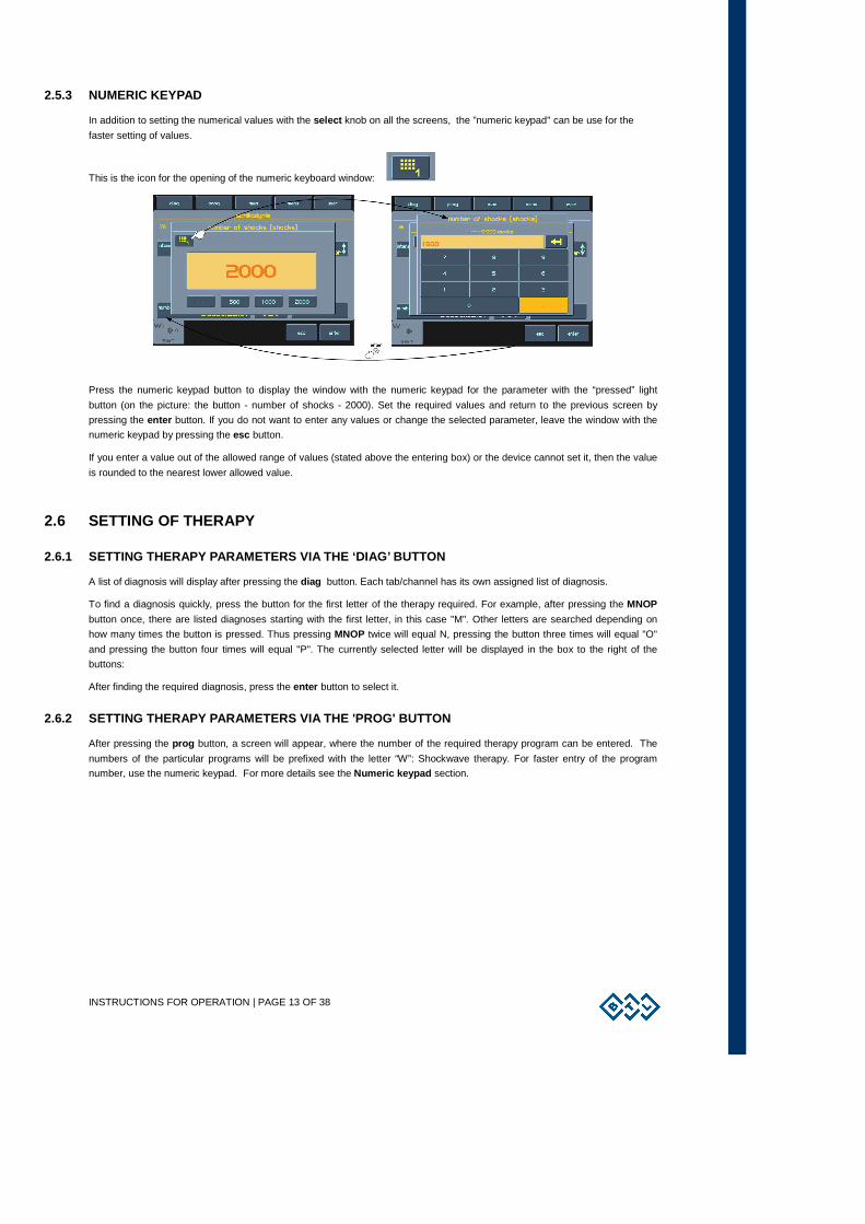
2.5.3 NUMERIC KEYPAD
In addition to setting the numerical values with the select knob on all the screens, the ”numeric keypad" can be use for the
faster setting of values.
This is the icon for the opening of the numeric keyboard window:
Press the numeric keypad button to display the window with the numeric keypad for the parameter with the “pressed” light
button (on the picture: the button - number of shocks - 2000). Set the required values and return to the previous screen by
pressing the enter button. If you do not want to enter any values or change the selected parameter, leave the window with the
numeric keypad by pressing the esc button.
If you enter a value out of the allowed range of values (stated above the entering box) or the device cannot set it, then the value
is rounded to the nearest lower allowed value.
2.6 SETTING OF THERAPY
2.6.1 SETTING THERAPY PARAMETERS VIA THE ‘DIAG’ BUT TON
A list of diagnosis will display after pressing the diag button. Each tab/channel has its own assigned list of diagnosis.
To find a diagnosis quickly, press the button for the first letter of the therapy required. For example, after pressing the MNOP
button once, there are listed diagnoses starting with the first letter, in this case "M". Other letters are searched depending on
how many times the button is pressed. Thus pressing MNOP twice will equal N, pressing the button three times will equal "O"
and pressing the button four times will equal "P". The currently selected letter will be displayed in the box to the right of the
buttons:
After finding the required diagnosis, press the enter button to select it.
2.6.2 SETTING THERAPY PARAMETERS VIA THE 'PROG' BUT TON
After pressing the prog button, a screen will appear, where the number of the required therapy program can be entered. The
numbers of the particular programs will be prefixed with the letter “W”: Shockwave therapy. For faster entry of the program
number, use the numeric keypad. For more details see the Numeric keypad section.
INSTRUCTIONS FOR OPERATION | PAGE 14 OF 38
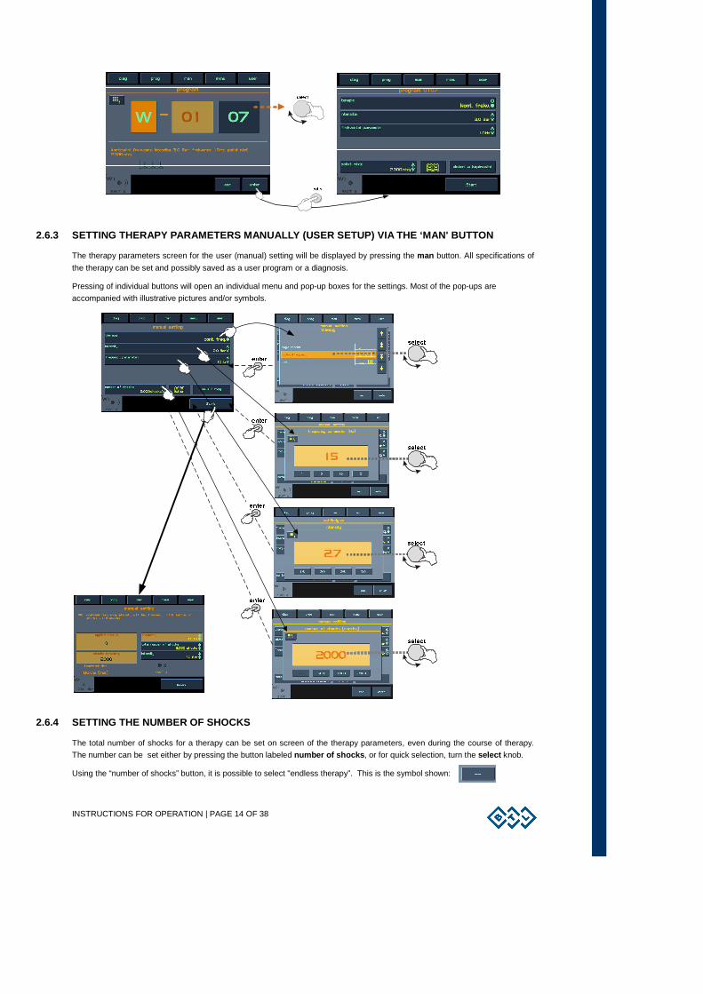
2.6.3 SETTING THERAPY PARAMETERS MANUALLY (USER SET UP) VIA THE ‘MAN' BUTTON
The therapy parameters screen for the user (manual) setting will be displayed by pressing the man button. All specifications of
the therapy can be set and possibly saved as a user program or a diagnosis.
Pressing of individual buttons will open an individual menu and pop-up boxes for the settings. Most of the pop-ups are
accompanied with illustrative pictures and/or symbols.
2.6.4 SETTING THE NUMBER OF SHOCKS
The total number of shocks for a therapy can be set on screen of the therapy parameters, even during the course of therapy.
The number can be set either by pressing the button labeled number of shocks , or for quick selection, turn the select knob.
Using the “number of shocks” button, it is possible to select "endless therapy”. This is the symbol shown:
INSTRUCTIONS FOR OPERATION | PAGE 15 OF 38
The endless therapy option allows for an infinite number of shocks, that can be applied from the start of the therapy.
The end of therapy is not limited to the number of shocks.
2.6.5 SETTING THERAPY INTENSITY
The intensity (power) of the shockwave therapy can be set on the therapy parameters screen, even during the course of
therapy. After pressing the intensity button it is possible to set the intensity either by means of the numeric keypad, present
values written on the buttons or by the select knob. During therapy, the intensity value can only be changed by means of the
select knob.
INSTRUCTIONS FOR OPERATION | PAGE 16 OF 38
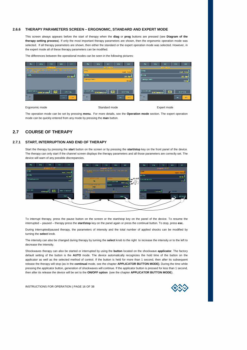
2.6.6 THERAPY PARAMETERS SCREEN – ERGONOMIC, STANDA RD AND EXPERT MODE
This screen always appears before the start of therapy when the diag or prog buttons are pressed (see Diagram of the therapy setting process ). If only the most important therapy parameters are shown, then the ergonomic operation mode was
selected. If all therapy parameters are shown, then either the standard or the expert operation mode was selected. However, in
the expert mode all of these therapy parameters can be modified.
The differences between the operational modes can be seen in the following pictures:
+
Ergonomic mode Standard mode Expert mode
The operation mode can be set by pressing menu. For more details, see the Operation mode section. The expert operation
mode can be quickly entered from any mode by pressing the man button.
2.7 COURSE OF THERAPY
2.7.1 START, INTERRUPTION AND END OF THERAPY
Start the therapy by pressing the start button on the screen or by pressing the start/stop key on the front panel of the device.
The therapy can only start if the channel screen displays the therapy parameters and all those parameters are correctly set. The
device will warn of any possible discrepancies.
To interrupt therapy, press the pause button on the screen or the start/stop key on the panel of the device. To resume the
interrupted – paused – therapy press the start/stop key on the panel again or press the continual button. To stop, press esc.
During interrupted/paused therapy, the parameters of intensity and the total number of applied shocks can be modified by
turning the select knob.
The intensity can also be changed during therapy by turning the select knob to the right to increase the intensity or to the left to
decrease the intensity.
Shockwaves therapy can also be started or interrupted by using the button located on the shockwave applicator . The factory
default setting of the button is the AUTO mode. The device automatically recognizes the hold time of the button on the
applicator as well as the selected method of control. If the button is held for more than 1 second, then after its subsequent
release the therapy will stop (as in the continual mode, see the chapter APPLICATOR BUTTON MODE) . During the time while
pressing the applicator button, generation of shockwaves will continue. If the applicator button is pressed for less than 1 second,
then after its release the device will be set to the ON/OFF option (see the chapter APPLICATOR BUTTON MODE ).
INSTRUCTIONS FOR OPERATION | PAGE 17 OF 38
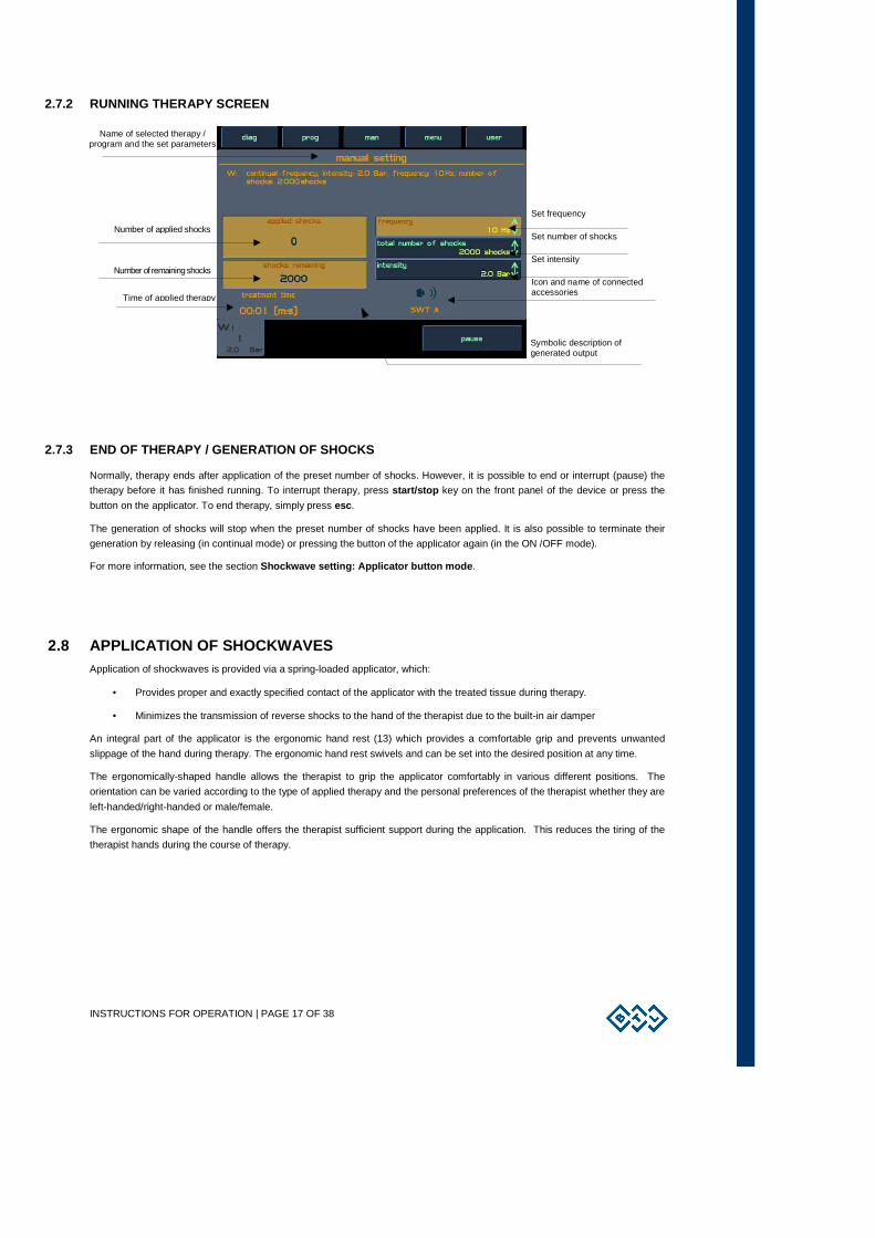
2.7.2 RUNNING THERAPY SCREEN
2.7.3 END OF THERAPY / GENERATION OF SHOCKS
Normally, therapy ends after application of the preset number of shocks. However, it is possible to end or interrupt (pause) the
therapy before it has finished running. To interrupt therapy, press start/stop key on the front panel of the device or press the
button on the applicator. To end therapy, simply press esc .
The generation of shocks will stop when the preset number of shocks have been applied. It is also possible to terminate their
generation by releasing (in continual mode) or pressing the button of the applicator again (in the ON /OFF mode).
For more information, see the section Shockwave setting: Applicator button mode .
2.8 APPLICATION OF SHOCKWAVES Application of shockwaves is provided via a spring-loaded applicator, which:
• Provides proper and exactly specified contact of the applicator with the treated tissue during therapy.
• Minimizes the transmission of reverse shocks to the hand of the therapist due to the built-in air damper
An integral part of the applicator is the ergonomic hand rest (13) which provides a comfortable grip and prevents unwanted
slippage of the hand during therapy. The ergonomic hand rest swivels and can be set into the desired position at any time.
The ergonomically-shaped handle allows the therapist to grip the applicator comfortably in various different positions. The
orientation can be varied according to the type of applied therapy and the personal preferences of the therapist whether they are
left-handed/right-handed or male/female.
The ergonomic shape of the handle offers the therapist sufficient support during the application. This reduces the tiring of the
therapist hands during the course of therapy.
Name of selected therapy / program and the set parameters
Set intensity
Number of applied shocks Set number of shocks
Set frequency
Number of remaining shocks
Time of applied therapy
Icon and name of connected accessories
Symbolic description of generated output
INSTRUCTIONS FOR OPERATION | PAGE 18 OF 38
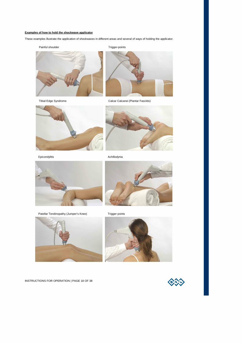
Examples of how to hold the shockwave applicator
These examples illustrate the application of shockwaves in different areas and several of ways of holding the applicator.
Painful shoulder Trigger-points
Tibial Edge Syndrome Calcar Calcanei (Plantar Fasciitis)
Patellar Tendinopathy (Jumper’s Knee)
Achillodynia
Trigger points
Epicondylitis

INSTRUCTIONS FOR OPERATION | PAGE 19 OF 38
2.9 SAVING THERAPY
A particular operation can selected after pressing the “save” button. Depending on which operation is selected,
a chart with the appropriate data will be shown. An example of the procedure is displayed on the following screens.
It is always possible to save the therapy after setting its parameters, for example from the screen of therapy parameters – see
the chapter Therapy parameters screen . The following information is saved for each shockwave therapy program:
• Frequency
• Number of shocks
• Intensity
To save a therapy, enter:
• The name of the diagnosis (therapy): This will be displayed in list of diagnosis under the diag button.
• The program number: This will be displayed among the programs under the prog button.
• The description and/or additional information: This will be displayed in both lists below the line.
After entering this data, it is possible to assign a unique name to that particular therapy program. The name of the therapy
program will consist of the letter “W” (for shockWave therapy) and a number from 8000 to 8999. The device will automatically
offer the lowest available number in this range or it can be chosen by the user. For example, the resulting program number
could be: “W-8001”
You will find the saved therapy in the list of diagnoses under the name of the user diagnose or in the list of programs under the
number assigned by you (or automatically). If you choose to save therapy with adding it to the client data, the therapy will
display also after selecting the client in the list of his/her assigned therapies.
2.10 USER SETTINGS: THE ‘USER’ BUTTON By pressing the user button, the menu with options regarding the data saved by the user will be displayed. Additionally, certain
“special" functions of the shockwave generator will be displayed as well:
• Clients
• User diagnoses / programs
• Recent therapies
INSTRUCTIONS FOR OPERATION | PAGE 20 OF 38
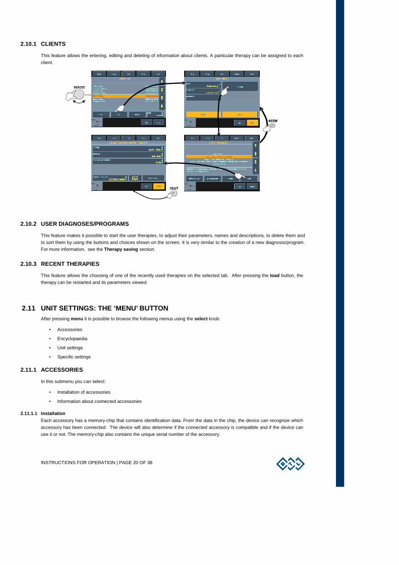
2.10.1 CLIENTS
This feature allows the entering, editing and deleting of information about clients. A particular therapy can be assigned to each
client.
2.10.2 USER DIAGNOSES/PROGRAMS
This feature makes it possible to start the user therapies, to adjust their parameters, names and descriptions, to delete them and
to sort them by using the buttons and choices shown on the screen. It is very similar to the creation of a new diagnosis/program.
For more information, see the Therapy saving section.
2.10.3 RECENT THERAPIES
This feature allows the choosing of one of the recently used therapies on the selected tab. After pressing the load button, the
therapy can be restarted and its parameters viewed.
2.11 UNIT SETTINGS: THE ‘MENU’ BUTTON After pressing menu it is possible to browse the following menus using the select knob:
• Accessories
• Encyclopaedia
• Unit settings
• Specific settings
2.11.1 ACCESSORIES
In this submenu you can select:
• Installation of accessories
• Information about connected accessories
2.11.1.1 Installation
Each accessory has a memory-chip that contains identification data. From the data in the chip, the device can recognize which
accessory has been connected. The device will also determine if the connected accessory is compatible and if the device can
use it or not. The memory-chip also contains the unique serial number of the accessory.
INSTRUCTIONS FOR OPERATION | PAGE 21 OF 38
The memory-chip contains a lot of information and reading it takes from 30 seconds to 2 minutes. The “installation of
accessories” function serves for faster functioning of the unit. After the installation, under normal operation of the device only the
serial number of the accessory is read from the accessory’s memory and the other information is read from the device’s
memory. During the installation process, follow the instructions on the screen. In particular:
• all therapies must be completed/stopped during installation
• only one accessory may be connected to the unit at a time.
These guidelines are necessary for decreasing electromagnetic interference that could cause improper reading of the memory
data.
2.11.1.2 Information
Displays the information about connected accessories such as the name of the accessory, its serial number, the number of
alreadyapplied shocks etc.
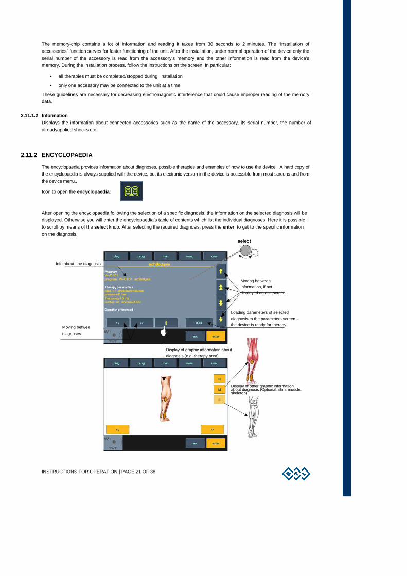
2.11.2 ENCYCLOPAEDIA
The encyclopaedia provides information about diagnoses, possible therapies and examples of how to use the device. A hard copy of
the encyclopaedia is always supplied with the device, but its electronic version in the device is accessible from most screens and from
the device menu..
Icon to open the encyclopaedia :
After opening the encyclopaedia following the selection of a specific diagnosis, the information on the selected diagnosis will be
displayed. Otherwise you will enter the encyclopaedia’s table of contents which list the individual diagnoses. Here it is possible
to scroll by means of the select knob. After selecting the required diagnosis, press the enter to get to the specific information
on the diagnosis.
Info about the diagnosis
Moving between
information, if not
displayed on one screen
Loading parameters of selected
diagnosis to the parameters screen –
the device is ready for therapy Moving betwee
diagnoses
Display of graphic information about
diagnosis (e.g. therapy area)
Display of other graphic information about diagnosis (Optional: skin, muscle, skeleton)
INSTRUCTIONS FOR OPERATION | PAGE 22 OF 38
2.11.3 UNIT SETTINGS
This submenu offers the options of setting and displaying these parameters:
• Password setting
• Sound setting
• Screen saver and auto switch-off
• Colour setting
• Setting of display contrast
• Date and time setting
• Language setting
• Operation mode
• Touch panel calibration
• User options
• Setting of HW key
• Unit information
• Unlocking code
• Service functions
2.11.3.1 Password Setting
Allows the setting or changing of the device’s password which is required by the device after the switch-on. Without entering the
password, further work with the device is impossible. The device standardly comes with this function disabled.
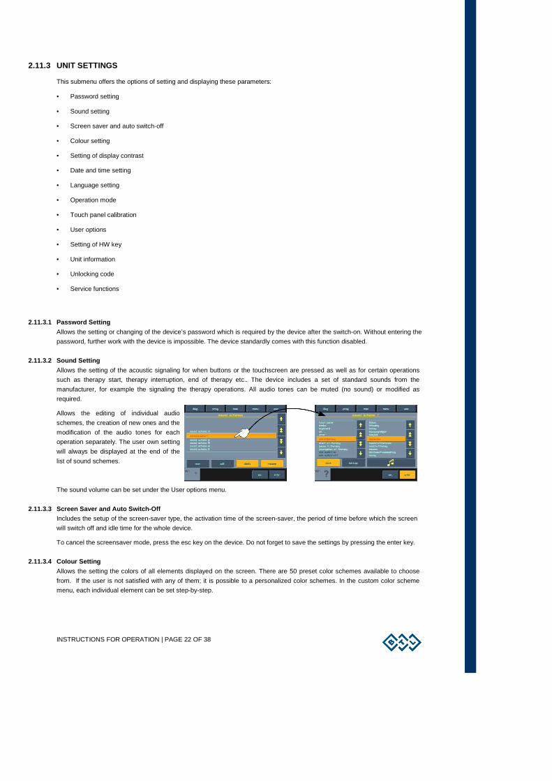
2.11.3.2 Sound Setting
Allows the setting of the acoustic signaling for when buttons or the touchscreen are pressed as well as for certain operations
such as therapy start, therapy interruption, end of therapy etc.. The device includes a set of standard sounds from the
manufacturer, for example the signaling the therapy operations. All audio tones can be muted (no sound) or modified as
required.
Allows the editing of individual audio
schemes, the creation of new ones and the
modification of the audio tones for each
operation separately. The user own setting
will always be displayed at the end of the
list of sound schemes.
The sound volume can be set under the User options menu.
2.11.3.3 Screen Saver and Auto Switch-Off
Includes the setup of the screen-saver type, the activation time of the screen-saver, the period of time before which the screen
will switch off and idle time for the whole device.
To cancel the screensaver mode, press the esc key on the device. Do not forget to save the settings by pressing the enter key.
2.11.3.4 Colour Setting
Allows the setting the colors of all elements displayed on the screen. There are 50 preset color schemes available to choose
from. If the user is not satisfied with any of them; it is possible to a personalized color schemes. In the custom color scheme
menu, each individual element can be set step-by-step.
INSTRUCTIONS FOR OPERATION | PAGE 23 OF 38
2.11.3.5 Setting of Display Contrast
Allows the setting of the optimum contrast (readability) of the display by turning the select knob.
Since the contrast of the screen depends on various factors, such as the temperature of the room, there is a faster and direct
way of setting the screen contrast. To quickly change the contrast, turn the “select” knob while simultaneously holding the enter
and esc keys.
2.11.3.6 Date and Time Setting
Allows the setting of the date and time for the device.
2.11.3.7 Language Setting
Allows the setting of the preferred language of the texts displayed on the device’s screen. The factory default is English.
2.11.3.8 Operation Mode
Allows the selection of one of the three therapuetic modes. See the Therapy Parameters Screen: Ergonomic, Standard and
Expert Modes section. The factory default is the ergonomic mode.
The differences between the operation modes consist of the possibilities of modification of therapy settings on the screen, which
always appears before starting therapy by using of the "diag" or "prog" button. The expert mode of operation can be entered
anytime by pressing the "man" button.
Ergonomic mode: The user will only see the most important therapy parameters and can change accessories and therapy
time.
Standard mode : The user will see all information about the therapy and can change accessories and therapy time.
Expert mode : The user will see and can change all therapy parameters.
The differences between the modes can be best seen on the therapy settings screen, which will always appears before starting
of therapy.
2.11.3.9 Touch Panel Calibration
If the buttons on the touch screen do not react when pressed, the touch screen needs calibration. The process of calibration is
shown on the screen. During calibration, use the touch-pen (stylus) and follow the on-screen instructions. Calibration, if not
successful, can be interrupted at any time by pressing the esc button.
To verify the touch screen adjustments, use the "touch panel function test" function.
2.11.3.10 User Options
This submenu allows the setting and displaying of the following parameters:
• direction of movement of menu (standard / reverse)
• sorting of diagnoses (in ascending order / in descending order)
• tabs position (top / bottom)
• sound volume
2.11.3.11 Setting of HW Key
The device can be remotely reconfigured. If it is later decided to purchase the upgrade, the manufacturer (distributor) will send
the 64-digit code (the so-called “HW key”) that when entered will reconfigure its hardware according to that key. For the actual
HW configuration see the next entry, Unit information.
2.11.3.12 Unit Information
Shows specific information about the device; the serial number, the device type, the firmware version, etc. It also contains the
information of when the device will operate – so called "device validity". If the operation of the device is time limited, this item
indicates until which date the device stays fully functional.
2.11.3.13 Unlock Code
If the operation of the device is time limited, then in this item you can enter the so-called "unlocking code" for cancellation of the
operational time limitation of the device.
INSTRUCTIONS FOR OPERATION | PAGE 24 OF 38
2.11.3.14 Service Functions
• repair of files
Checks the file storage system of the device, the system of saved information. It will repair possible errors, delete empty files,
etc. We recommend using this feature in the event of a lack of memory space, if the device rejects saving any data, or if you are
in doubt that some data may have been lost.
• file system formatting
Should be use only if the repair of damaged files feature did not help. Unfortunately, when this feature is used the entire memory
is re-formatted and all the user-data and the user setup of the device will be lost.
• delete accessories
Deletes all the previously installed accessory data. It is to be used when accessories were incorrectly installed (with bad
“scattered" picture shown on the tab), when the connected accessories cannot be detected (with a permanently displayed
question mark on the tab), or when there are other accessory related problems.
• default setting without loss of user data
Restores all functions of the device to the factory default settings. However, all user–data related to clients, programmed
therapies, etc. will stay saved.
2.11.4 SPECIFIC SETTINGS
2.11.4.1 Applicator Button Mode
This allows the selection of one of the three different types of modes for the applicator.The choices are:
• AUTO mode
• Continual mode
• ON/OFF mode
In AUTO mode, the device automatically recognizes the hold time of the button on the applicator and the selected way of
control it. If the button is pressed for more than 1 second, then after its subsequent release therapy will stop. This will be the
same in the continual mode (See below). During the time it takes to press the button , the generation of shockwaves will be in
progress.
If the button of the applicator is pressed for less than 1 second, then after its release the device will be set to the ON/OFF mode
option (see below).
In continual mode, the generation of the preset shockwaves is accomplished by only one press of the button on the
shockwave applicator. To end the generation of shockwaves, it is necessary to press the button on the applicator.
In ON/OFF mode, it is necessary to hold the button of the applicator pressed throughout the duration of the application of
shockwaves. Releasing the button stops the generation of shockwaves.
2.11.4.2 Applicator Kit Replacement Wizard
If, after a certain amount of time, the applicator stops generating shockwaves correctly, it is possible to change wom-out
applicator parts. Follow the instructions detailed in the Procedure of worn-out tube and roller replacement . Install this
replaced kit according to the displayed instructions.
Procedure for the applicator replacement kit:
1. Connect the applicator to the device.
2. Start the applicator kit replacement guide program..
3. Disconnect the original applicator from the device and complete the replacement of worn-out part following the step-by-step
instructions shown in the guide
4. After completion of the replacement re-connect the applicator back to the device.
5. Complete the steps shown in the guide.
6. The replaced kit has been successfully installed.
LIST OF STANDARD AND OPTIONAL ACCESSORIES | PAGE 25 OF 38
3 LIST OF STANDARD AND OPTIONAL ACCESSORIES
The device is not designed for use with other accessories or other medical equipment other than those stated in this manual.
The first list is of all standard accessories that are supplied with the device. The second list is of the optional accessories
available from BTL.
For more detailed information on individual accessories, see the enclosed leaflet.
Standard accessories:
• 1x shockwave applicator with multi-focus shock transmitter Ø 15mm
• 1x replaceable multi-focus shock transmitter Ø 9mm
• 1x replaceable focusing shock transmitter Ø 15mm
• 1x exchangeable kit (includes a spare set of O-rings)
• 1x applicator holder
• 1x gel 1000 ml
• 1x power cord
• 1x spare fuse T6.3A,L,250V
• 1x User’s Manual on CD
Optional accessories:
• transport case for the BTL-6000 SWT Topline
• additional shockwave applicator with focusing shock transmitter
• gel 300 ml
MAINTENANCE AND SAFETY INSTRUCTIONS | PAGE 26 OF 38
4 MAINTENANCE AND SAFETY INSTRUCTIONS
A service inspection including the measuring of all parameters of the device and relevant recalibration must be performed at
intervals shorter than 30 months. The inspection and recalibration must be performed by an authorized BTL service department.
If the inspection is not done at 30-month intervals, the manufacturer does not guarantee the technical parameters or safe
operation of the product.
To keep the device clean, do not store or use it in extremely dusty environment for a long time. Do not immerse it in any liquid.
Before each use, checks that the device and its accessories (especially cables) are not mechanically or otherwise damaged. Do
not use the device if it is damaged!
Exterior cleaning of the device:
Use a soft cloth slightly moistened with water or with a 2% detergent solution to clean the exterior of the BTL-6000 SWT Topline
device and its parts. Never use cleaning agents containing alcohol, ammonia, benzine, thinners, etc. Never use abrasive
cleaning materials which will scratch the device's surfaces. No parts of the device require sterilization. Care should be given to
prevent water or other liquids from getting inside the device.
Cleaning and maintenance of accessories which come into contact with the patient:
Clean and disinfect after each client using approved cleaning agents. For example, Sekusept, Bacilol, and Incidur Spray can be
used. For the cables of accessories, use Incidur Spray and the alike. DO NOT USE SOLVENTS!!!
The exterior surface of the shock transmitter can be washed with warm water with its cap on. However, to completely remove
all of the contact gel from the shock transmitter, it will be necessary to unscrew the shock transmitter and clean it.
Fuse replacement:
The fuse is placed in the round black boxes on the rear panel. During replacement, check the correctness of the fuse being
inserted. This action should only be done by a person acquainted with this procedure!
Before replacement, make sure that the main power switch of the device is in the “0” position and the adapter is unplugged from
the unit. Turn the segment of the fuse box to the left using a flathead screwdriver or coin in the slot to remove the fuse. Insert a
new fuse and turn it to the right.
Do not use fuses other than those stated above the fuse box!
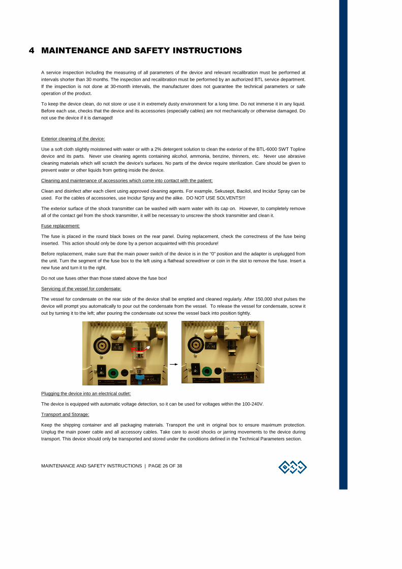
Servicing of the vessel for condensate:
The vessel for condensate on the rear side of the device shall be emptied and cleaned regularly. After 150,000 shot pulses the
device will prompt you automatically to pour out the condensate from the vessel. To release the vessel for condensate, screw it
out by turning it to the left; after pouring the condensate out screw the vessel back into position tightly.
Plugging the device into an electrical outlet:
The device is equipped with automatic voltage detection, so it can be used for voltages within the 100-240V.
Transport and Storage:
Keep the shipping container and all packaging materials. Transport the unit in original box to ensure maximum protection.
Unplug the main power cable and all accessory cables. Take care to avoid shocks or jarring movements to the device during
transport. This device should only be transported and stored under the conditions defined in the Technical Parameters section.
MAINTENANCE AND SAFETY INSTRUCTIONS | PAGE 27 OF 38
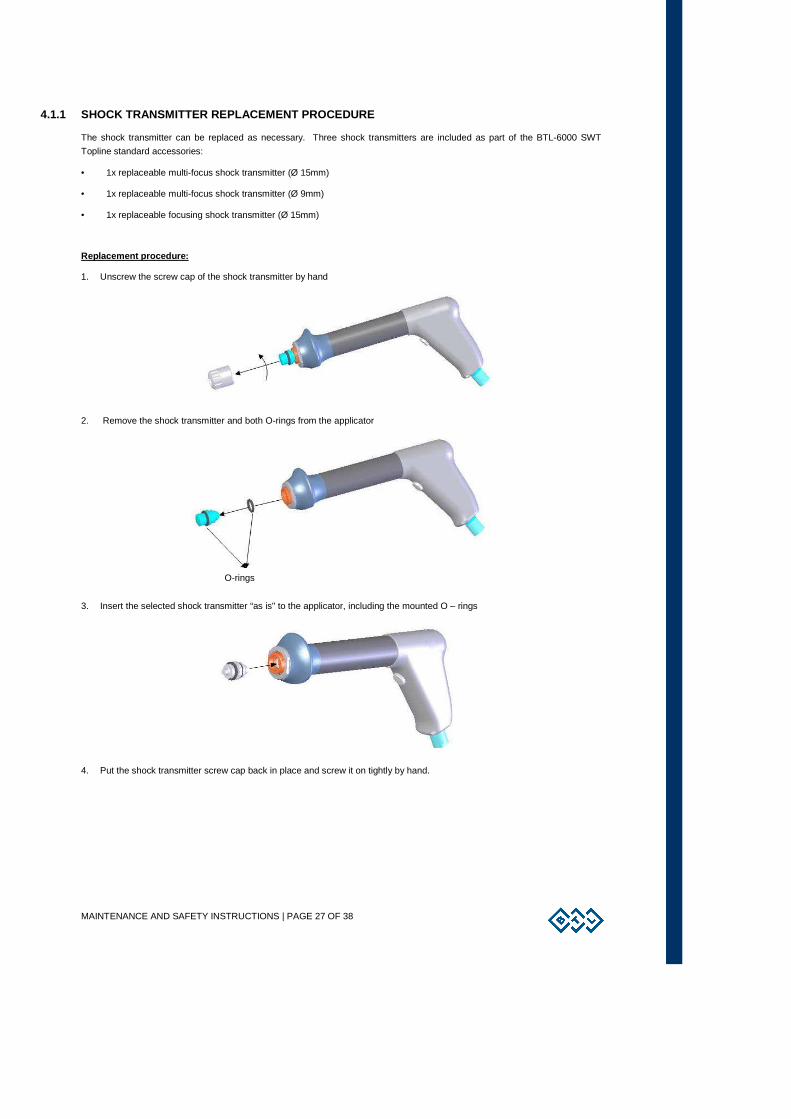
4.1.1 SHOCK TRANSMITTER REPLACEMENT PROCEDURE
The shock transmitter can be replaced as necessary. Three shock transmitters are included as part of the BTL-6000 SWT
Topline standard accessories:
• 1x replaceable multi-focus shock transmitter (Ø 15mm)
• 1x replaceable multi-focus shock transmitter (Ø 9mm)
• 1x replaceable focusing shock transmitter (Ø 15mm)
Replacement procedure:
1. Unscrew the screw cap of the shock transmitter by hand
2. Remove the shock transmitter and both O-rings from the applicator
3. Insert the selected shock transmitter “as is" to the applicator, including the mounted O – rings
4. Put the shock transmitter screw cap back in place and screw it on tightly by hand.
O-rings
MAINTENANCE AND SAFETY INSTRUCTIONS | PAGE 28 OF 38
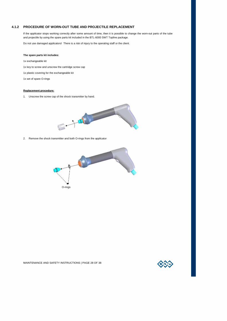
4.1.2 PROCEDURE OF WORN-OUT TUBE AND PROJECTILE REP LACEMENT
If the applicator stops working correctly after some amount of time, then it is possible to change the worn-out parts of the tube
and projectile by using the spare parts kit included in the BTL-6000 SWT Topline package.
Do not use damaged applicators! There is a risk of injury to the operating staff or the client.
The spare parts kit includes:
1x exchangeable kit
1x key to screw and unscrew the cartridge screw cap
1x plastic covering for the exchangeable kit
1x set of spare O-rings
Replacement procedure:
1. Unscrew the screw cap of the shock transmitter by hand.
2. Remove the shock transmitter and both O-rings from the applicator
O-rings
MAINTENANCE AND SAFETY INSTRUCTIONS | PAGE 29 OF 38
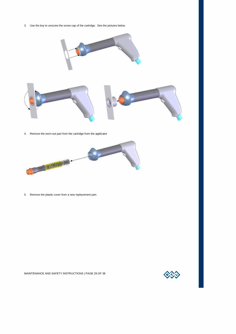
3. Use the key to unscrew the screw cap of the cartridge. See the pictures below.
4. Remove the worn-out part from the cartridge from the applicator
5. Remove the plastic cover from a new replacement part.
MAINTENANCE AND SAFETY INSTRUCTIONS | PAGE 30 OF 38
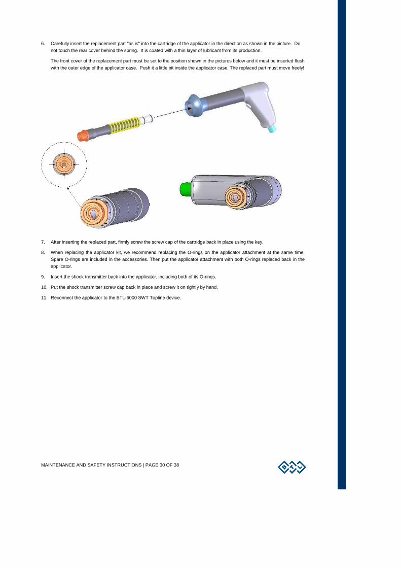
6. Carefully insert the replacement part "as is" into the cartridge of the applicator in the direction as shown in the picture. Do
not touch the rear cover behind the spring. It is coated with a thin layer of lubricant from its production.
The front cover of the replacement part must be set to the position shown in the pictures below and it must be inserted flush
with the outer edge of the applicator case. Push it a little bit inside the applicator case. The replaced part must move freely!
7. After inserting the replaced part, firmly screw the screw cap of the cartridge back in place using the key.
8. When replacing the applicator kit, we recommend replacing the O-rings on the applicator attachment at the same time.
Spare O-rings are included in the accessories. Then put the applicator attachment with both O-rings replaced back in the
applicator.
9. Insert the shock transmitter back into the applicator, including both of its O-rings.
10. Put the shock transmitter screw cap back in place and screw it on tightly by hand.
11. Reconnect the applicator to the BTL-6000 SWT Topline device.
MAINTENANCE AND SAFETY INSTRUCTIONS | PAGE 31 OF 38
4.2 GENERAL SAFETY PRECAUTIONS
• Before turning on the device for the first time, read this manual carefully.
• The device may only be used under the supervision of the physician prescribed the treatment.
• All personnel must be properly trained before using the device. This training should include the servicing technique,
maintenance, verification of proper functioning and safety precautions associated with using the device.
• Shockwave therapy requires direct bodily contact, t herefore do not use it on damaged skin!
• Do not apply shockwave therapy: To areas of the bo dy with gas-containing organs, close to large nerve bundles or blood vessels, on the spinal cord or on the head !
• We do not recommend applying shockwave to the body parts under local anaesthesia.
• The device does not use any drugs, creams, gels or other substances which are an integral part or which are applied by
its use.
• The device is equipped with a protection system that prevents the connection of accessories other than those supplied by
the manufacturer. Consequently it will not operate with equipment from other manufacturers.
• Only the power supply adapter approved and supplied by the manufacturer, complying with the specifications listed in
Chapter Technical Parameters , may be connected to the device.
• The product complies with Class A emissions according to CISPR11, IEC 60601-1-2.
• Portable and mobile high-frequency communication devices (such as mobile phones) may affect the function of the device.
• The electrical cables which are to be connected to the device must be installed and tested according to the existing valid
standards (IEC 364). If it is not known whether cables are safe and/or correct, then they should be checked and/or
upgrade by an inspection engineer.
• Check whether the parameters of the main power supply correspond to the requirements of the device according to
Technical Parameters section
• The device requires the environmental conditions that are stated in the Technical Parameters section. It must not be used
in an environment where there is a danger of explosion or of water penetrating the device. The device cannot be in
connection with flammable anaesthetics or oxidizing gasses (O2, N2O, etc.).
• Do not place the device in direct sunlight or near strong electromagnetic fields to prevent mutual functionality influence. If
this happens, move the device further away from the source of interference or contact an authorized BTL service
department.
• Inspect the device thoroughly before each use. Look for loose cables, cracked cable insulation, cracks in the shockwave
applicator’s housing and functional behavioural differences in the display or the operating elements. If any anomalies or
inconsistencies are found, stop using the device and contact an authorized BTL service department. If the behaviour of
the device shows any divergences from the functionality procedures described in this user’s manual, stop using the device
and contact an authorized BTL service department.
• If the device shows any defects or if there are any doubts concerning its correct and safe functioning, terminate therapy
immediately. If the source of the concern can be determine after a thorough study of the user's manual, then contact an
authorized BTL service department immediately. If the device is not used in accordance with this manual or if it is used
when the device exhibits functional differences from those stated in this manual, then BTL is not responsible for any
damage to or caused by the device.
• Do not try to open, remove protective covers, or dismantle the device for any reason. There is a danger of electrical shock
and/or serious injury. Even the replacement of the lithium battery and the air micro-filter must be done an authorized BTL
service department only!
• All material and parts which come into direct contact with the client's body (such as cleaning agents, the applicators,
electrodes) must respectively comply with the standards related to irritants, allergens, toxins, geotaxis and carcinogens
(ISO 10993-1, ISO 10993-3, ISO 10993 5). The user is responsible for all these materials and parts if they were not
supplied by an authorized BTL equipment supplier.

MAINTENANCE AND SAFETY INSTRUCTIONS | PAGE 32 OF 38
• The connectors for accessories, as well as the other connectors, must not be used for connecting anything else other than
what they are designed for. There is a danger of electrical shock and/or serious damage to the device.
• The device does not use or emit any toxic substances during its operation, storage or transport under the stated
conditions.
• Before the start of therapy make sure that all set parameters comply with your requirements.
• To terminate operation, do not use the main power switch! Instead, press the "start/stop".
• The time interval between turning off the main power switch and turning it back on must be at least 3 seconds.
• Place the device so that it is possible to disconnect the connector of the power supply adapter quickly and easily from the
device, or the male plug of the power supply adapter from the mains. To disconnect from the mains, unplug the male plug
of the power supply adapter from the mains socket outlet
• If it is necessary to discard the device, the lithium battery must be removed. The removed battery must be disposed
according to local hazardous waste disposal requirements. Do not place the device in municipal waste containers. The
device itself does not contain any toxic materials which could harm the environment when disposed of ecologically
• The device and its accessories must be used in compliance with this manual.
• The device must be placed out of the reach of children.
• The device does not contain any components, except for the fuse and parts containing in the shockwave transmitter
replacement kit, which can be repaired or replaced by the user. Do not remove the cover from the control unit. All repairs
must be done by an authorized BTL service department.
• Do not disconnect an applicator during therapy.
4.3 USED SYMBOLS
Warning, the values of energy, electric current or voltage may exceed the safe values of energy, current or voltage.
The applied part is of BF type. Only accessories connected thus marked connectors may be applied on the client.
Protection class II device
4.4 WARRANTY
This product is warranted from the actual delivery date against defects in material and workmanship. The warranty period is
twenty four (24) months. Product accessories are warranted for a period of six (6) months, except for applicators that are
warranted for twenty four (24) months. The above stated warranty is valid provided such defects are not due to ordinary wear
and tear or improper use or handling by the purchaser or its sub-purchaser. Improper handling or use inter allia include any use
of the product not in accordance with the manual; improper cleaning; any damage caused due to improper installation, and
servicing of the product by unqualified personnel.
In case of any error or defect in the product, the exclusive remedy for the purchaser, and the entire liability of the company in
contract, tort or otherwise, is limited to the correction of such error or defect by repairing or replacement, at the sole discretion of
the company. The warranty set forth above is made in lieu of all other warranties, express or implied, including but not limited to
all implied warranties of merchantility or fitness for a particular purpose. BTL's sole obligations under this warranty are as set
forth herein. In no event shall BTL be liable for any lost revenue or profits, direct, indirect, special, incidental or consequential
damages of any kind.
TECHNICAL PARAMETERS | PAGE 33 OF 38
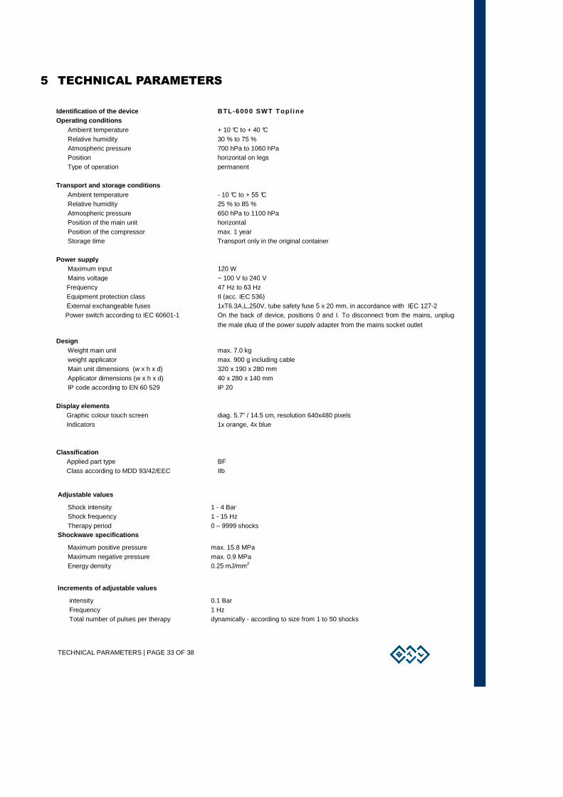
5 TECHNICAL PARAMETERS
Identification of the device BTL -6000 SWT Top l i ne Operating conditions
Ambient temperature + 10 °C to + 40 °C Relative humidity 30 % to 75 % Atmospheric pressure 700 hPa to 1060 hPa Position horizontal on legs Type of operation permanent
Transport and storage conditions
Ambient temperature - 10 °C to + 55 °C Relative humidity 25 % to 85 % Atmospheric pressure 650 hPa to 1100 hPa Position of the main unit horizontal Position of the compressor max. 1 year Storage time Transport only in the original container
Power supply
Maximum input 120 W Mains voltage ~ 100 V to 240 V Frequency 47 Hz to 63 Hz Equipment protection class II (acc. IEC 536) External exchangeable fuses 1xT6.3A,L,250V, tube safety fuse 5 x 20 mm, in accordance with IEC 127-2
Power switch according to IEC 60601-1 On the back of device, positions 0 and I. To disconnect from the mains, unplug
the male plug of the power supply adapter from the mains socket outlet Design
Weight main unit max. 7.0 kg weight applicator max. 900 g including cable Main unit dimensions (w x h x d) 320 x 190 x 280 mm Applicator dimensions (w x h x d) 40 x 280 x 140 mm IP code according to EN 60 529 IP 20
Display elements
Graphic colour touch screen diag. 5.7" / 14.5 cm, resolution 640x480 pixels Indicators 1x orange, 4x blue
Classification Applied part type BF Class according to MDD 93/42/EEC IIb
Adjustable values
Shock intensity 1 - 4 Bar Shock frequency 1 - 15 Hz Therapy period 0 – 9999 shocks
Shockwave specifications
Maximum positive pressure max. 15.8 MPa Maximum negative pressure max. 0.9 MPa Energy density 0.25 mJ/mm2
Increments of adjustable values
intensity 0.1 Bar Frequency 1 Hz Total number of pulses per therapy dynamically - according to size from 1 to 50 shocks

TECHNICAL PARAMETERS | PAGE 34 OF 38
Technical parameters of the Switching Power Supply Adapter BTL-4000 SWT 150W Design
Weight – device only 780 g approx.
Dimensions (w x h x d) 142 x 76 x 43,7 mm
Covering grade according to EN 60 529 IP20
Class according to IEC 60601-1 II
Class according to MDD 93/42 EEC Ilb
Type of operation permanent
Operating conditions
Ambient temperature 10 °C to + 40 °C
Relative humidity 30 % to 75 %
Atmospheric pressure 700 hPa to 1060 hPa
Position Horizontal – on legs
Transport and storage conditions
Ambient temperature - 10 °C to + 55 °C
Relative humidity 25 % to 85 %
Atmospheric pressure 650 hPa to 1100 hPa
Position any
Storage time 1 year
TECHNICAL PARAMETERS | PAGE 35 OF 38
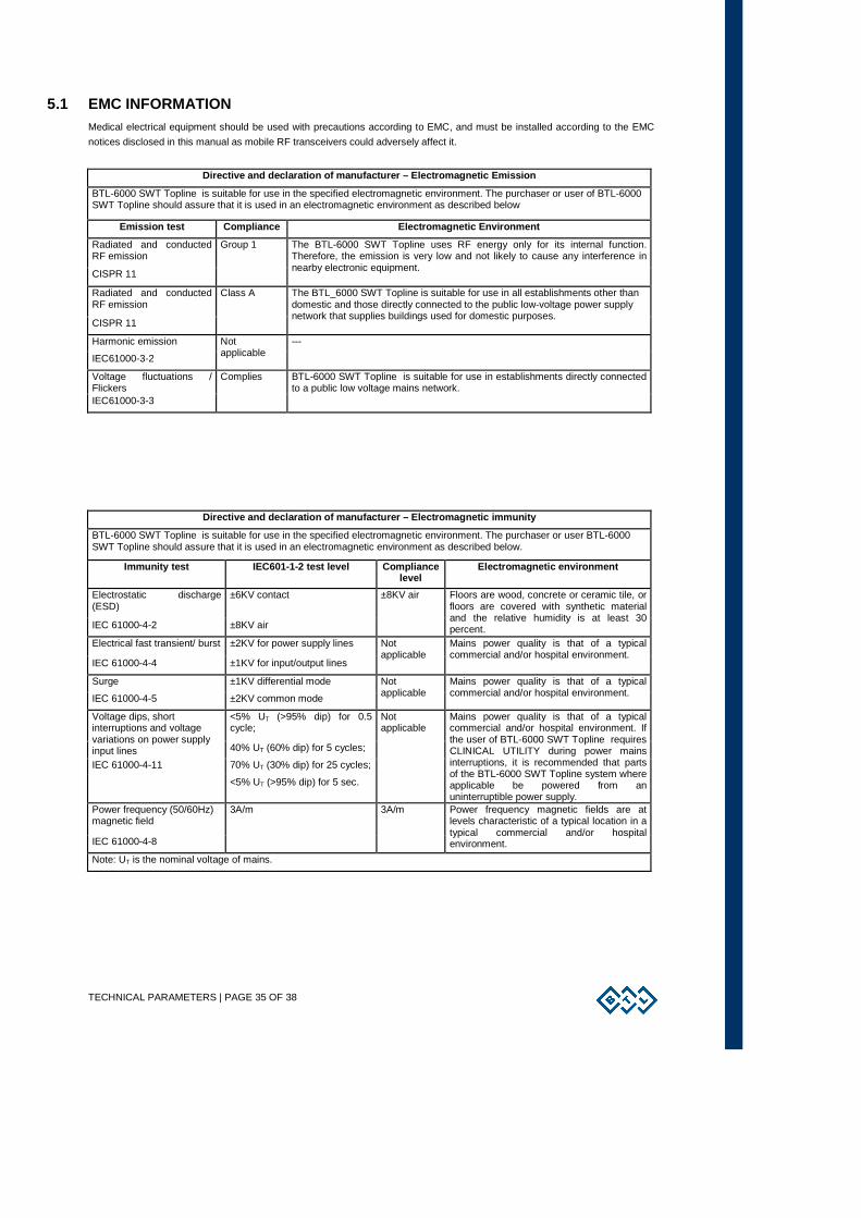
5.1 EMC INFORMATION Medical electrical equipment should be used with precautions according to EMC, and must be installed according to the EMC
notices disclosed in this manual as mobile RF transceivers could adversely affect it.
Directive and declaration of manufacturer – Electro magnetic Emission
BTL-6000 SWT Topline is suitable for use in the specified electromagnetic environment. The purchaser or user of BTL-6000 SWT Topline should assure that it is used in an electromagnetic environment as described below
Emission test Compliance Electromagnetic Environmen t
Radiated and conducted RF emission
CISPR 11
Group 1 The BTL-6000 SWT Topline uses RF energy only for its internal function. Therefore, the emission is very low and not likely to cause any interference in nearby electronic equipment.
Radiated and conducted RF emission
CISPR 11
Class A The BTL_6000 SWT Topline is suitable for use in all establishments other than domestic and those directly connected to the public low-voltage power supply network that supplies buildings used for domestic purposes.
Harmonic emission
IEC61000-3-2
Not applicable
---
Voltage fluctuations / Flickers IEC61000-3-3
Complies BTL-6000 SWT Topline is suitable for use in establishments directly connected to a public low voltage mains network.
Directive and declaration of manufacturer – Electro magnetic immunity
BTL-6000 SWT Topline is suitable for use in the specified electromagnetic environment. The purchaser or user BTL-6000 SWT Topline should assure that it is used in an electromagnetic environment as described below.
Immunity test IEC601-1-2 test level Compliance level
Electromagnetic environment
Electrostatic discharge (ESD)
±6KV contact
IEC 61000-4-2 ±8KV air
±8KV air Floors are wood, concrete or ceramic tile, or floors are covered with synthetic material and the relative humidity is at least 30 percent.
Electrical fast transient/ burst ±2KV for power supply lines
IEC 61000-4-4 ±1KV for input/output lines
Not applicable
Mains power quality is that of a typical commercial and/or hospital environment.
Surge ±1KV differential mode
IEC 61000-4-5 ±2KV common mode
Not applicable
Mains power quality is that of a typical commercial and/or hospital environment.
<5% UT (>95% dip) for 0.5 cycle;
Voltage dips, short interruptions and voltage variations on power supply input lines 40% UT (60% dip) for 5 cycles;
IEC 61000-4-11 70% UT (30% dip) for 25 cycles;
<5% UT (>95% dip) for 5 sec.
Not applicable
Mains power quality is that of a typical commercial and/or hospital environment. If the user of BTL-6000 SWT Topline requires CLINICAL UTILITY during power mains interruptions, it is recommended that parts of the BTL-6000 SWT Topline system where applicable be powered from an uninterruptible power supply.
Power frequency (50/60Hz) magnetic field
IEC 61000-4-8
3A/m 3A/m Power frequency magnetic fields are at levels characteristic of a typical location in a typical commercial and/or hospital environment.
Note: UT is the nominal voltage of mains.

TECHNICAL PARAMETERS | PAGE 36 OF 38
Directive and declaration of manufacturer – Electro magnetic immunity
BTL-6000 SWT Topline is suitable for use in the specified electromagnetic environment. The purchaser or user of BTL-6000 SWT Topline should assure that it is used in an electromagnetic environment as described below.
Immunity test IEC601-1-2 test level
Compliance level
Electromagnetic environment
Conducted RF 3Veff Portable and mobile RF communications equipment are used no closer to any part of BTL-6000 SWT Topline, including cables, than the Recommended Separation Distance calculated the formula written below.
IEC 6100-4-6 150KHz - 80MHz Recommended Separation distance:
Not applicable
d=[3,5/V1]√P
Radiated RF 3V/m d=[3,5/3V/m]√P; IEC 61000-4-3 80MHz – 2,5GHz (80MHz – 800MHz) d=[7/3V/m]√P; (800MHz – 2,5GHz) where:
3V/m
P is the highest radiated power disclosed by the manufacturer of transmitter [W]; d is the recommended separation distance [m].
1. note: in case of frequency 80MHz or 800 MHz, the formula for the higher range is applicable.
2. note: These are guidelines. Actual conditions may vary.
Recommended separation distance
BTL-6000 SWT Topline is intended to be used in electromagnetic environment with controlled RF disturbances. The purchaser or user of BTL-6000 SWT Topline may help to reduce electromagnetic disturbances by defining the separation distance between the transportable or mobile RF telecommunication equipment (transmitters) and BTL-6000 SWT Topline, depending on the highest output power of the telecommunication equipment.
Separation distance in function of the frequency of the transmitter [m]
150KHz – 80MHz 80MHz – 800MHz 800MHz – 2,5GHz The highest output power of the transmitter [W] d=[3,5/V 1]√P d=[3,5/E 1]√P d=[7/E 1]√P
0,01 Not applicable 0,12 0,23
0,1 Not applicable 0,38 0,73
1 Not applicable 1,2 2,3
10 Not applicable 3,8 7,3
100 Not applicable 12 23
If this table does not contain the highest output power of the transmitter, the d separation distance [m] can be calculated by the formula, depending on the frequency of the transmitter, where P is the rated highest output power of the transmitter [W].
1. note: in case of frequency 80MHz or 800 MHz, the formula for the higher range is applicable.
2. note: These are guidelines. Actual conditions may vary.
TECHNICAL PARAMETERS | PAGE 37 OF 38
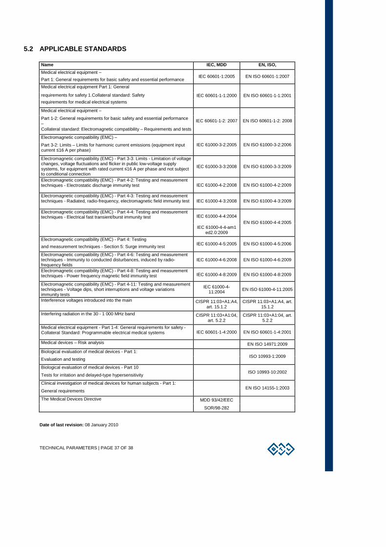
5.2 APPLICABLE STANDARDS
Name IEC, MDD EN, ISO,
Medical electrical equipment –
Part 1: General requirements for basic safety and essential performance IEC 60601-1:2005 EN ISO 60601-1:2007
Medical electrical equipment Part 1: General
requirements for safety 1.Collateral standard: Safety
requirements for medical electrical systems IEC 60601-1-1:2000 EN ISO 60601-1-1:2001
Medical electrical equipment –
Part 1-2: General requirements for basic safety and essential performance – Collateral standard: Electromagnetic compatibility – Requirements and tests
IEC 60601-1-2: 2007 EN ISO 60601-1-2: 2008
Electromagnetic compatibility (EMC) –
Part 3-2: Limits – Limits for harmonic current emissions (equipment input current ≤16 A per phase)
IEC 61000-3-2:2005 EN ISO 61000-3-2:2006
Electromagnetic compatibility (EMC) - Part 3-3: Limits - Limitation of voltage changes, voltage fluctuations and flicker in public low-voltage supply systems, for equipment with rated current ≤16 A per phase and not subject to conditional connection
IEC 61000-3-3:2008 EN ISO 61000-3-3:2009
Electromagnetic compatibility (EMC) - Part 4-2: Testing and measurement techniques - Electrostatic discharge immunity test IEC 61000-4-2:2008 EN ISO 61000-4-2:2009
Electromagnetic compatibility (EMC) - Part 4-3: Testing and measurement techniques - Radiated, radio-frequency, electromagnetic field immunity test IEC 61000-4-3:2008 EN ISO 61000-4-3:2009
IEC 61000-4-4:2004 Electromagnetic compatibility (EMC) - Part 4-4: Testing and measurement techniques - Electrical fast transient/burst immunity test
IEC 61000-4-4-am1 ed2.0:2009
EN ISO 61000-4-4:2005
Electromagnetic compatibility (EMC) - Part 4: Testing
and measurement techniques - Section 5: Surge immunity test IEC 61000-4-5:2005 EN ISO 61000-4-5:2006
Electromagnetic compatibility (EMC) - Part 4-6: Testing and measurement techniques - Immunity to conducted disturbances, induced by radio-frequency fields
IEC 61000-4-6:2008 EN ISO 61000-4-6:2009
Electromagnetic compatibility (EMC) - Part 4-8: Testing and measurement techniques - Power frequency magnetic field immunity test IEC 61000-4-8:2009 EN ISO 61000-4-8:2009
Electromagnetic compatibility (EMC) - Part 4-11: Testing and measurement techniques - Voltage dips, short interruptions and voltage variations immunity tests
IEC 61000-4-11:2004 EN ISO 61000-4-11:2005
Interference voltages introduced into the main CISPR 11:03+A1:A4, art. 15.1.2
CISPR 11:03+A1:A4, art. 15.1.2
Interfering radiation in the 30 - 1 000 MHz band CISPR 11:03+A1:04, art. 5.2.2
CISPR 11:03+A1:04, art. 5.2.2
Medical electrical equipment - Part 1-4: General requirements for safety - Collateral Standard: Programmable electrical medical systems IEC 60601-1-4:2000 EN ISO 60601-1-4:2001
Medical devices – Risk analysis EN ISO 14971:2009
Biological evaluation of medical devices - Part 1:
Evaluation and testing ISO 10993-1:2009
Biological evaluation of medical devices - Part 10
Tests for irritation and delayed-type hypersensitivity ISO 10993-10:2002
Clinical investigation of medical devices for human subjects - Part 1:
General requirements EN ISO 14155-1:2003
MDD 93/42/EEC The Medical Devices Directive
SOR/98-282
Date of last revision: 08 January 2010
TECHNICAL PARAMETERS | PAGE 38 OF 38
5.3 MANUFACTURER
This product is manufactured in accordance with the EU Medical Devices Directive by:
BTL Industries Ltd.
161 Cleveland Way
Stevenage
Hertfordshire
SG1 6BU
United Kingdom
E-mail: [email protected]
http://www.btlnet.com
For service, please contact our service department at [email protected].
© All rights reserved. No part of this manual may be reproduced, saved or transferred by any means including electronic,
mechanical, and photographic without the prior written approval from BTL Industries Limited.
BTL Industries Limited operates on a policy of continuous development. Therefore, we reserve the right to make changes and/or
improvements to the product described in this manual without any prior notice.
Except as required by applicable law, no warranties of any kind, either expressed or implied, are made for the accuracy,
reliability or contents of this document. BTL Industries Limited reserves the right to revise or withdraw this document at any time
without prior notice.