Embed Size (px)
Citation preview
Lambert, L. A., Cooper, J. E., & Nangia, R. K. (2016). BucklingAlleviation for Joined-Wing Aircraft. Journal of Aircraft, 53(3), 811-821.https://doi.org/10.2514/1.C033426
Peer reviewed versionLicense (if available):CC BY-NCLink to published version (if available):10.2514/1.C033426
Link to publication record in Explore Bristol ResearchPDF-document
This is the author accepted manuscript (AAM). The final published version (version of record) is available onlinevia AIAA at http://arc.aiaa.org/doi/10.2514/1.C033426. Please refer to any applicable terms of use of thepublisher.
University of Bristol - Explore Bristol ResearchGeneral rights
This document is made available in accordance with publisher policies. Please cite only thepublished version using the reference above. Full terms of use are available:http://www.bristol.ac.uk/red/research-policy/pure/user-guides/ebr-terms/
Buckling Alleviation for Joined-Wing Aircraft
Luke A. Lambert,∗ Jonathan E. Cooper† and Raj K. Nangia‡
University of Bristol, BS8 1TR, United Kingdom
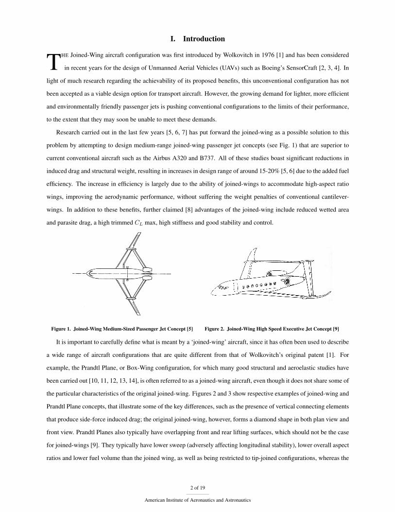
A novel mechanism is described that increases the critical buckling load of the rear wing of joined-
wing aircraft, in an effort to reduce structural weight. The benefits of the joined-wing configuration
are briefly discussed, along with its current limitations. The behaviour of the modified structure
under lift is investigated by conducting a number of linear structural analyses for varying geometric
arrangements. It is shown that the mechanism, called the Buckling Alleviation Component (BAC), is
effective in reducing structural weight for a significant proportion of aircraft geometries, even though
there is a trade-off between rear wing buckling load and front wing root bending moment. A more
detailed structural model is used to investigate the effect of geometric structural nonlinearities. The
nonlinear analysis shows that the BAC delays the onset of nonlinear behaviour and that the critical
buckling loads of the conventional configuration are drastically overestimated by the linear analysis,
which means that BAC performs much more effectively than the initial linear analysis suggests.
Nomenclature
CL Lift coefficient
Hj Height of join location
Ht Height of tail
LBAC Length of BAC
Mr Root bending moment of front wing
M ′r Normalised wing root bending moment,
MrJW /MrCW
Pc Critical buckling load of rear wing
V Volume of structural material
X Horizontal distance between wing roots
(Excluding BAC length)
hj Non-dimensional join height, Hj/Ht
ht Non-dimensional tail height, Ht/X
j Non-dimensional spanwise join location, srw/s
lBAC Non-dimensional BAC length, LBAC/s
s Semi-span
Symbols
α Sweep angle of front wing
β Sweep angle of rear wing
ÆR Aspect Ratio
Subscripts
fw Front wing
rw Rear wing
CW Conventional Wing Configuration
IN Inboard section
JW Joined-Wing Configuration∗Research Associate, Department of Aerospace Engineering. [email protected]†RAEng Airbus Sir George White Chair of Aerospace Engineering, Department of Aerospace Engineering, AFAIAA.‡Honorary Research Fellow, Department of Aerospace Engineering.
1 of 19
American Institute of Aeronautics and Astronautics
I. Introduction
THE Joined-Wing aircraft configuration was first introduced by Wolkovitch in 1976 [1] and has been considered
in recent years for the design of Unmanned Aerial Vehicles (UAVs) such as Boeing’s SensorCraft [2, 3, 4]. In
light of much research regarding the achievability of its proposed benefits, this unconventional configuration has not
been accepted as a viable design option for transport aircraft. However, the growing demand for lighter, more efficient
and environmentally friendly passenger jets is pushing conventional configurations to the limits of their performance,
to the extent that they may soon be unable to meet these demands.
Research carried out in the last few years [5, 6, 7] has put forward the joined-wing as a possible solution to this
problem by attempting to design medium-range joined-wing passenger jet concepts (see Fig. 1) that are superior to
current conventional aircraft such as the Airbus A320 and B737. All of these studies boast significant reductions in
induced drag and structural weight, resulting in increases in design range of around 15-20% [5, 6] due to the added fuel
efficiency. The increase in efficiency is largely due to the ability of joined-wings to accommodate high-aspect ratio
wings, improving the aerodynamic performance, without suffering the weight penalties of conventional cantilever-
wings. In addition to these benefits, further claimed [8] advantages of the joined-wing include reduced wetted area
and parasite drag, a high trimmed CL max, high stiffness and good stability and control.
Figure 1. Joined-Wing Medium-Sized Passenger Jet Concept [5] Figure 2. Joined-Wing High Speed Executive Jet Concept [9]
It is important to carefully define what is meant by a ‘joined-wing’ aircraft, since it has often been used to describe
a wide range of aircraft configurations that are quite different from that of Wolkovitch’s original patent [1]. For
example, the Prandtl Plane, or Box-Wing configuration, for which many good structural and aeroelastic studies have
been carried out [10, 11, 12, 13, 14], is often referred to as a joined-wing aircraft, even though it does not share some of
the particular characteristics of the original joined-wing. Figures 2 and 3 show respective examples of joined-wing and
Prandtl Plane concepts, that illustrate some of the key differences, such as the presence of vertical connecting elements
that produce side-force induced drag; the original joined-wing, however, forms a diamond shape in both plan view and
front view. Prandtl Planes also typically have overlapping front and rear lifting surfaces, which should not be the case
for joined-wings [9]. They typically have lower sweep (adversely affecting longitudinal stability), lower overall aspect
ratios and lower fuel volume than the joined wing, as well as being restricted to tip-joined configurations, whereas the
2 of 19
American Institute of Aeronautics and Astronautics
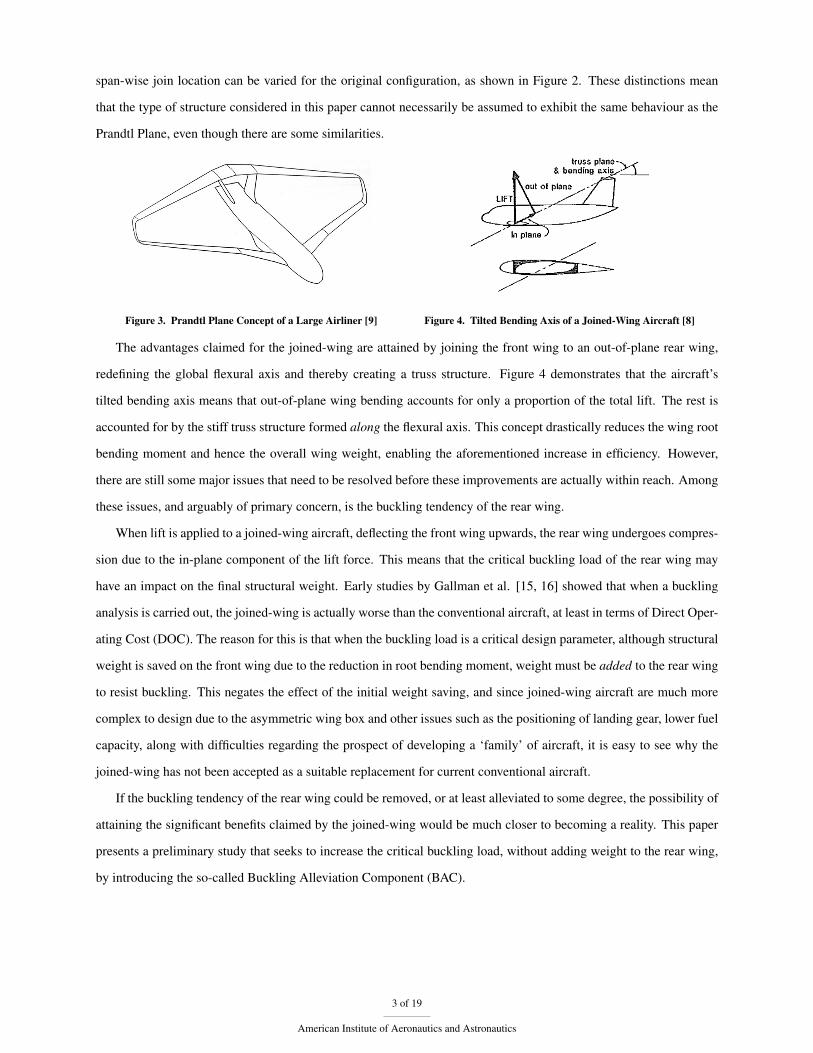
span-wise join location can be varied for the original configuration, as shown in Figure 2. These distinctions mean
that the type of structure considered in this paper cannot necessarily be assumed to exhibit the same behaviour as the
Prandtl Plane, even though there are some similarities.
Figure 3. Prandtl Plane Concept of a Large Airliner [9] Figure 4. Tilted Bending Axis of a Joined-Wing Aircraft [8]
The advantages claimed for the joined-wing are attained by joining the front wing to an out-of-plane rear wing,
redefining the global flexural axis and thereby creating a truss structure. Figure 4 demonstrates that the aircraft’s
tilted bending axis means that out-of-plane wing bending accounts for only a proportion of the total lift. The rest is
accounted for by the stiff truss structure formed along the flexural axis. This concept drastically reduces the wing root
bending moment and hence the overall wing weight, enabling the aforementioned increase in efficiency. However,
there are still some major issues that need to be resolved before these improvements are actually within reach. Among
these issues, and arguably of primary concern, is the buckling tendency of the rear wing.
When lift is applied to a joined-wing aircraft, deflecting the front wing upwards, the rear wing undergoes compres-
sion due to the in-plane component of the lift force. This means that the critical buckling load of the rear wing may
have an impact on the final structural weight. Early studies by Gallman et al. [15, 16] showed that when a buckling
analysis is carried out, the joined-wing is actually worse than the conventional aircraft, at least in terms of Direct Oper-
ating Cost (DOC). The reason for this is that when the buckling load is a critical design parameter, although structural
weight is saved on the front wing due to the reduction in root bending moment, weight must be added to the rear wing
to resist buckling. This negates the effect of the initial weight saving, and since joined-wing aircraft are much more
complex to design due to the asymmetric wing box and other issues such as the positioning of landing gear, lower fuel
capacity, along with difficulties regarding the prospect of developing a ‘family’ of aircraft, it is easy to see why the
joined-wing has not been accepted as a suitable replacement for current conventional aircraft.
If the buckling tendency of the rear wing could be removed, or at least alleviated to some degree, the possibility of
attaining the significant benefits claimed by the joined-wing would be much closer to becoming a reality. This paper
presents a preliminary study that seeks to increase the critical buckling load, without adding weight to the rear wing,
by introducing the so-called Buckling Alleviation Component (BAC).
3 of 19
American Institute of Aeronautics and Astronautics
II. The Buckling Alleviation Component
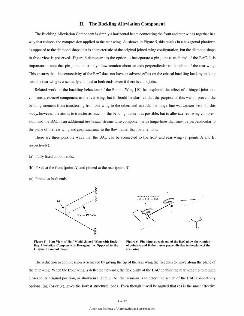
The Buckling Alleviation Component is simply a horizontal beam connecting the front and rear wings together in a
way that reduces the compression applied to the rear wing. As shown in Figure 5, this results in a hexagonal planform
as opposed to the diamond shape that is characteristic of the original joined-wing configuration, but the diamond shape
in front view is preserved. Figure 6 demonstrates the option to incorporate a pin joint at each end of the BAC. It is
important to note that pin joints must only allow rotation about an axis perpendicular to the plane of the rear wing.
This ensures that the connectivity of the BAC does not have an adverse effect on the critical buckling load, by making
sure the rear wing is essentially clamped at both ends, even if there is a pin joint.
Related work on the buckling behaviour of the Prandtl Wing [10] has explored the effect of a hinged joint that
connects a vertical component to the rear wing, but it should be clarified that the purpose of this was to prevent the
bending moment from transferring from one wing to the other, and as such, the hinge-line was stream-wise. In this
study, however, the aim is to transfer as much of the bending moment as possible, but to alleviate rear wing compres-
sion, and the BAC is an additional horizontal stream-wise component with hinge-lines that must be perpendicular to
the plane of the rear wing and perpendicular to the flow, rather than parallel to it.
There are three possible ways that the BAC can be connected to the front and rear wing (at points A and B,
respectively):
(a) Fully fixed at both ends,
(b) Fixed at the front (point A) and pinned at the rear (point B),
(c) Pinned at both ends.
Figure 5. Plan View of Half-Model Joined-Wing with Buck-ling Alleviation Component is Hexagonal as Opposed to theOriginal Diamond Shape
Figure 6. Pin joints at each end of the BAC allow the rotationof points A and B about axes perpendicular to the plane of therear wing
The reduction in compression is achieved by giving the tip of the rear wing the freedom to move along the plane of
the rear wing. When the front wing is deflected upwards, the flexibility of the BAC enables the rear wing tip to remain
closer to its original position, as shown in Figure 7. All that remains is to determine which of the BAC connectivity
options, (a), (b) or (c), gives the lowest structural loads. Even though it will be argued that (b) is the most effective
4 of 19
American Institute of Aeronautics and Astronautics
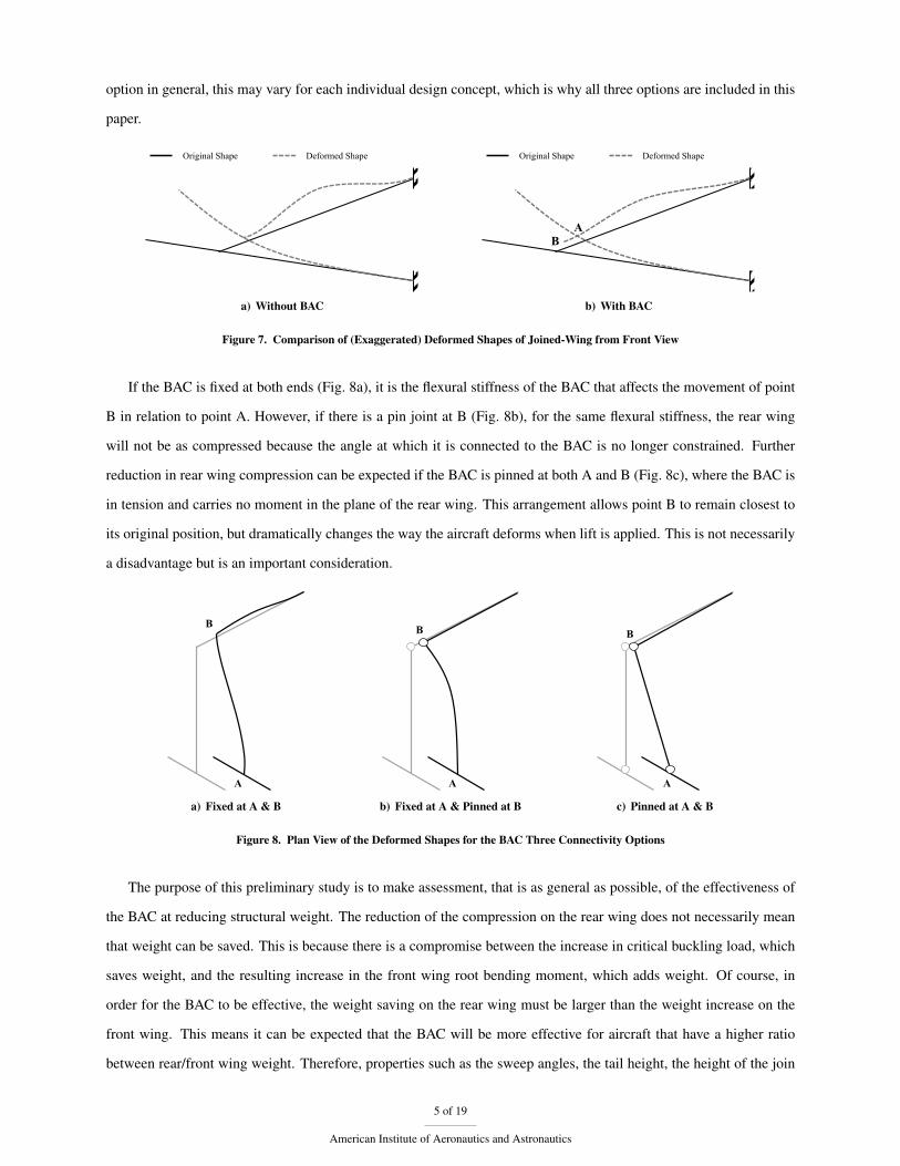
option in general, this may vary for each individual design concept, which is why all three options are included in this
paper.
Original Shape Deformed Shape
a) Without BAC
Original Shape Deformed Shape
B A
b) With BAC
Figure 7. Comparison of (Exaggerated) Deformed Shapes of Joined-Wing from Front View
If the BAC is fixed at both ends (Fig. 8a), it is the flexural stiffness of the BAC that affects the movement of point
B in relation to point A. However, if there is a pin joint at B (Fig. 8b), for the same flexural stiffness, the rear wing
will not be as compressed because the angle at which it is connected to the BAC is no longer constrained. Further
reduction in rear wing compression can be expected if the BAC is pinned at both A and B (Fig. 8c), where the BAC is
in tension and carries no moment in the plane of the rear wing. This arrangement allows point B to remain closest to
its original position, but dramatically changes the way the aircraft deforms when lift is applied. This is not necessarily
a disadvantage but is an important consideration.
A
B
a) Fixed at A & B
A
B
b) Fixed at A & Pinned at B
A
B
c) Pinned at A & B
Figure 8. Plan View of the Deformed Shapes for the BAC Three Connectivity Options
The purpose of this preliminary study is to make assessment, that is as general as possible, of the effectiveness of
the BAC at reducing structural weight. The reduction of the compression on the rear wing does not necessarily mean
that weight can be saved. This is because there is a compromise between the increase in critical buckling load, which
saves weight, and the resulting increase in the front wing root bending moment, which adds weight. Of course, in
order for the BAC to be effective, the weight saving on the rear wing must be larger than the weight increase on the
front wing. This means it can be expected that the BAC will be more effective for aircraft that have a higher ratio
between rear/front wing weight. Therefore, properties such as the sweep angles, the tail height, the height of the join
5 of 19
American Institute of Aeronautics and Astronautics

location (point A) and the length of the BAC itself, should have an impact on the effectiveness of the BAC. The model
used in this study to determine the nature of this impact is outlined in the following section.
It is important to note that, although this paper defines the effectiveness of the BAC purely in terms of structural
weight saving, it may offer other advantages such as improved stability and control due to the increased pitching
moment. Also, the BAC theoretically allows the aircraft to be ‘stretched’ to some some degree without the need to
completely redesign the wings, which is the main difficulty when it comes to developing a ‘family’ of aircraft. An
assessment of these additional advantages is beyond the scope of this paper, but may be the subject of future research.
III. A General Joined-Wing Beam Model
A. Finite Element Model
In order to determine the aircraft geometries for which the BAC is most effective (if at all), a large number of structural
analyses were carried out on a simple beam model, which is shown in Figure 9. The beam cross-sections are constant
along the wingspan but different for each wing. The rear wing typically has a higher aspect ratio than the front wing
because it generates only a small proportion of the total lift. In this case it was assumed that 15% of the total lift is
taken by the rear wing.
LBAC
s
α
β
a) Plan View
srw
Ht
Hj
b) Front View
Figure 9. Finite Element Model of the Joined-Wing with BAC
Even though the model does not contain any aerodynamic elements, the dimensions of the beam cross-section for
each wing are defined as proportions of the chord. Since the length of each wing is determined by the properties shown
in Figure 9, it is the aspect ratio of an individual wing that determines the dimensions of its wing box. All of the other
geometric parameters apart from the semi-span and the sweep angles are non-dimensionalised, enabling the model,
and therefore the findings, to be as general as possible.
6 of 19
American Institute of Aeronautics and Astronautics
B. Structural Analysis
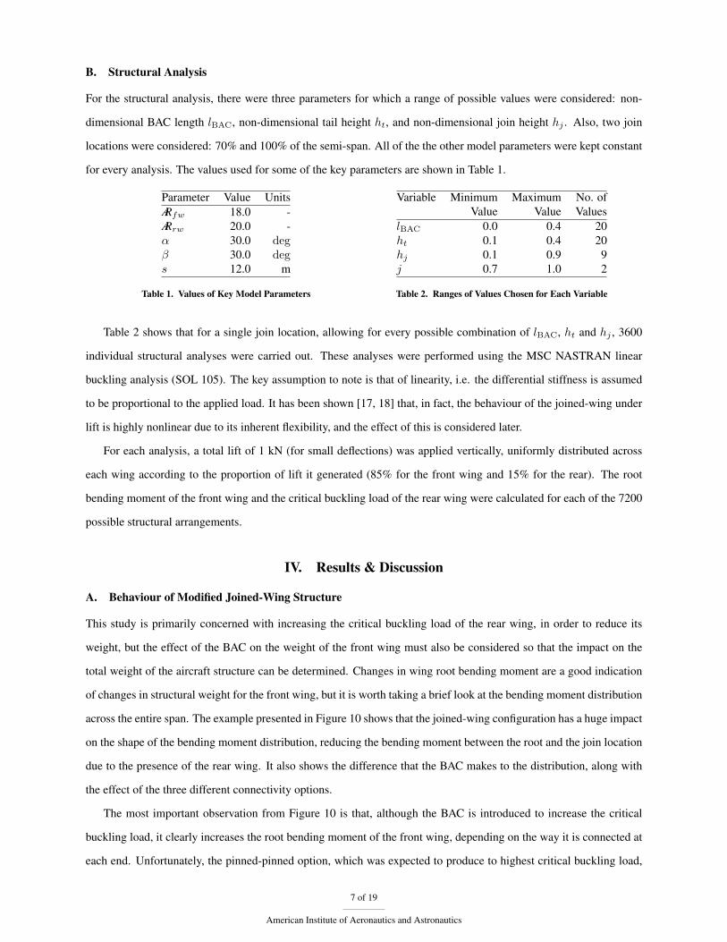
For the structural analysis, there were three parameters for which a range of possible values were considered: non-
dimensional BAC length lBAC, non-dimensional tail height ht, and non-dimensional join height hj . Also, two join
locations were considered: 70% and 100% of the semi-span. All of the the other model parameters were kept constant
for every analysis. The values used for some of the key parameters are shown in Table 1.
Parameter Value UnitsÆRfw 18.0 -ÆRrw 20.0 -α 30.0 degβ 30.0 degs 12.0 m
Table 1. Values of Key Model Parameters
Variable Minimum Maximum No. ofValue Value Values
lBAC 0.0 0.4 20ht 0.1 0.4 20hj 0.1 0.9 9j 0.7 1.0 2
Table 2. Ranges of Values Chosen for Each Variable
Table 2 shows that for a single join location, allowing for every possible combination of lBAC, ht and hj , 3600
individual structural analyses were carried out. These analyses were performed using the MSC NASTRAN linear
buckling analysis (SOL 105). The key assumption to note is that of linearity, i.e. the differential stiffness is assumed
to be proportional to the applied load. It has been shown [17, 18] that, in fact, the behaviour of the joined-wing under
lift is highly nonlinear due to its inherent flexibility, and the effect of this is considered later.
For each analysis, a total lift of 1 kN (for small deflections) was applied vertically, uniformly distributed across
each wing according to the proportion of lift it generated (85% for the front wing and 15% for the rear). The root
bending moment of the front wing and the critical buckling load of the rear wing were calculated for each of the 7200
possible structural arrangements.
IV. Results & Discussion
A. Behaviour of Modified Joined-Wing Structure
This study is primarily concerned with increasing the critical buckling load of the rear wing, in order to reduce its
weight, but the effect of the BAC on the weight of the front wing must also be considered so that the impact on the
total weight of the aircraft structure can be determined. Changes in wing root bending moment are a good indication
of changes in structural weight for the front wing, but it is worth taking a brief look at the bending moment distribution
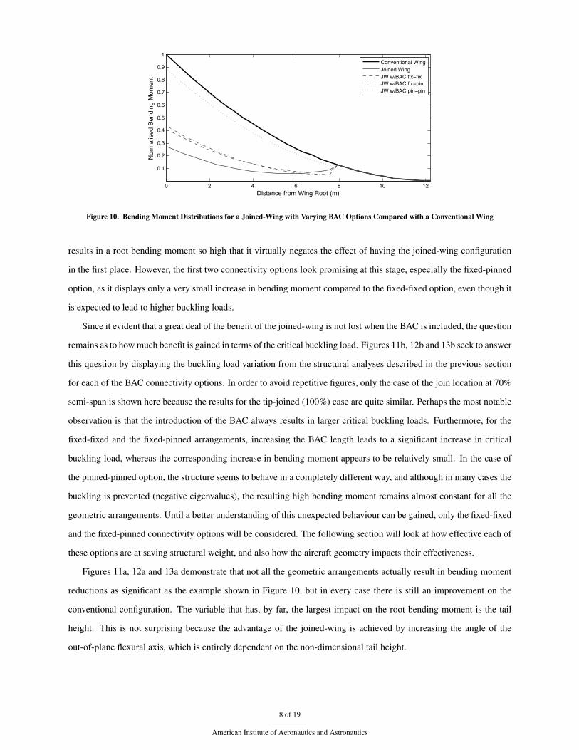
across the entire span. The example presented in Figure 10 shows that the joined-wing configuration has a huge impact
on the shape of the bending moment distribution, reducing the bending moment between the root and the join location
due to the presence of the rear wing. It also shows the difference that the BAC makes to the distribution, along with
the effect of the three different connectivity options.
The most important observation from Figure 10 is that, although the BAC is introduced to increase the critical
buckling load, it clearly increases the root bending moment of the front wing, depending on the way it is connected at
each end. Unfortunately, the pinned-pinned option, which was expected to produce to highest critical buckling load,
7 of 19
American Institute of Aeronautics and Astronautics
0 2 4 6 8 10 12
0.1
0.2
0.3
0.4
0.5
0.6
0.7
0.8
0.9
1
Distance from Wing Root (m)
Nor
mal
ised
Ben
ding
Mom
ent
Conventional WingJoined WingJW w/BAC fix−fixJW w/BAC fix−pinJW w/BAC pin−pin
Figure 10. Bending Moment Distributions for a Joined-Wing with Varying BAC Options Compared with a Conventional Wing
results in a root bending moment so high that it virtually negates the effect of having the joined-wing configuration
in the first place. However, the first two connectivity options look promising at this stage, especially the fixed-pinned
option, as it displays only a very small increase in bending moment compared to the fixed-fixed option, even though it
is expected to lead to higher buckling loads.
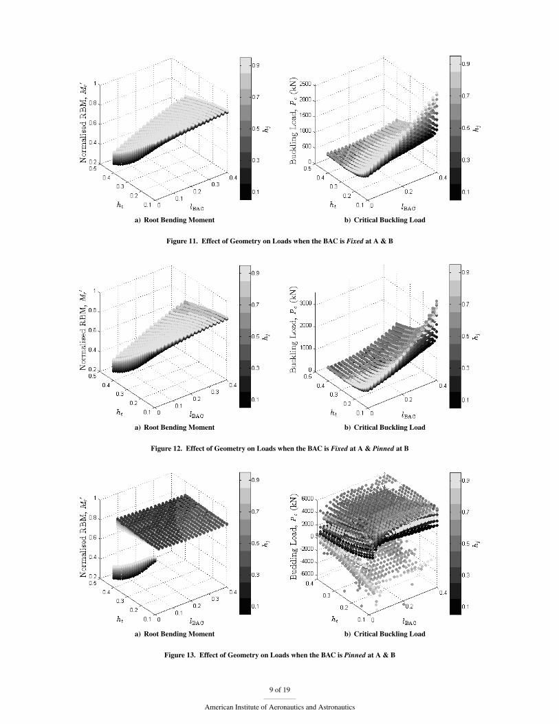
Since it evident that a great deal of the benefit of the joined-wing is not lost when the BAC is included, the question
remains as to how much benefit is gained in terms of the critical buckling load. Figures 11b, 12b and 13b seek to answer
this question by displaying the buckling load variation from the structural analyses described in the previous section
for each of the BAC connectivity options. In order to avoid repetitive figures, only the case of the join location at 70%
semi-span is shown here because the results for the tip-joined (100%) case are quite similar. Perhaps the most notable
observation is that the introduction of the BAC always results in larger critical buckling loads. Furthermore, for the
fixed-fixed and the fixed-pinned arrangements, increasing the BAC length leads to a significant increase in critical
buckling load, whereas the corresponding increase in bending moment appears to be relatively small. In the case of
the pinned-pinned option, the structure seems to behave in a completely different way, and although in many cases the
buckling is prevented (negative eigenvalues), the resulting high bending moment remains almost constant for all the
geometric arrangements. Until a better understanding of this unexpected behaviour can be gained, only the fixed-fixed
and the fixed-pinned connectivity options will be considered. The following section will look at how effective each of
these options are at saving structural weight, and also how the aircraft geometry impacts their effectiveness.
Figures 11a, 12a and 13a demonstrate that not all the geometric arrangements actually result in bending moment
reductions as significant as the example shown in Figure 10, but in every case there is still an improvement on the
conventional configuration. The variable that has, by far, the largest impact on the root bending moment is the tail
height. This is not surprising because the advantage of the joined-wing is achieved by increasing the angle of the
out-of-plane flexural axis, which is entirely dependent on the non-dimensional tail height.
8 of 19
American Institute of Aeronautics and Astronautics
a) Root Bending Moment b) Critical Buckling Load
Figure 11. Effect of Geometry on Loads when the BAC is Fixed at A & B
a) Root Bending Moment b) Critical Buckling Load
Figure 12. Effect of Geometry on Loads when the BAC is Fixed at A & Pinned at B
a) Root Bending Moment b) Critical Buckling Load
Figure 13. Effect of Geometry on Loads when the BAC is Pinned at A & B
9 of 19
American Institute of Aeronautics and Astronautics
B. Effectiveness of Buckling Alleviation Component
Since the root bending moment and the buckling load both have a linear impact on the weight of their respective wing,
in order to save weight, the ratio between the percentage increase in critical buckling load ∆Pc and the percentage
increase in root bending moment ∆Mr, must be greater than the ratio between the weight of the inboard section of
the front winga and the weight of the rear wing. Given that the material properties are the same for both wings, the
condition that must be satisfied in order for the BAC to be effective can be written as
∆Pc
∆Mr>Vfw IN
Vrw(1)
Also, since the wing box geometry is defined as a proportion of the chord, which is determined by the aspect ratio
for a given span, it is not necessary to calculate Vfw IN/Vrw for every single case. A very good approximation is given
by
VrwVfw IN
= j2cosα
cosβ
ÆR2fw
ÆR2rw
(2)
Combining (1) with (2), it follows that the BAC can be considered effective for the geometries that satisfy
∆Pc
∆Mr>
cosβÆR2rw
j2 cosαÆR2fw
(3)
It is essential to be clear at this point that in order to obtain meaningful results using Equation 3, we are only
interested in the changes in bending moment and buckling load that are a direct result of an increase in BAC length.
This is because it is only BAC effectiveness that is being investigated. In other words, the effects of changes in Ht and
Hj on ∆Pc and ∆Mr must be removed so that the results do not misrepresent the capability of the BAC.
In order to achieve this, the loads were normalised separately for every combination of ht and hj such that, for the
ith BAC length, the jth tail height and the kth join height
∆Pci,j,k =
{Pci,j,k
Pc(lBAC=0),j,k
− 1
}× 100% (4)
∆Mri,j,k =
{Mri,j,k
Mr(lBAC=0),j,k
− 1
}× 100% (5)
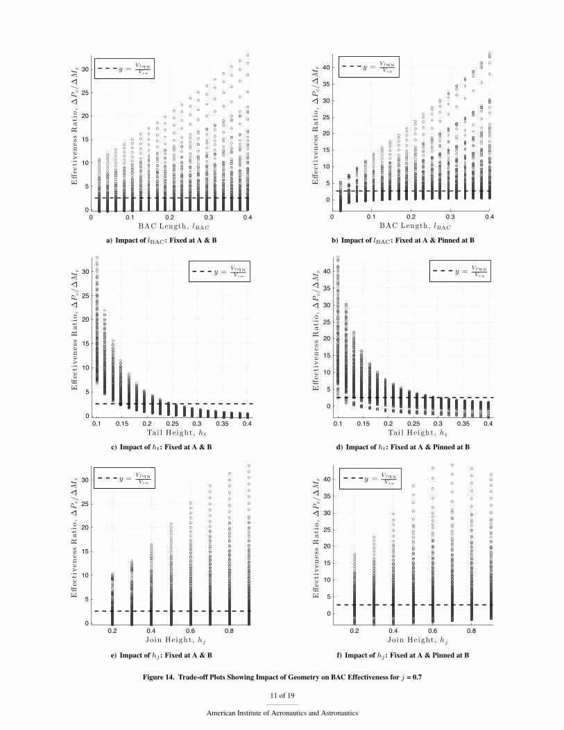
Although the impact of ht and hj on the loads has been removed, their impact on the effectiveness of the BAC can
now be shown by plotting these variables against the effectiveness ratios for each case and comparing their values to
the line y = Vfw IN/Vrw . These ‘trade-off’ plots are displayed for each join location in Figures 14 and 15, respectively.
aFigure 10 demonstrates that the weight of the outboard section will be unaffected by an increase in root bending moment because it actsindependently as a cantilever.
10 of 19
American Institute of Aeronautics and Astronautics
0 0.1 0.2 0.3 0.40
5
10
15
20
25
30
BAC Length, lBAC
Eff
ecti
ven
ess
Rati
o,
∆P
c/∆
Mr
y =V fwIN
Vrw
a) Impact of lBAC: Fixed at A & B
0 0.1 0.2 0.3 0.4
0
5
10
15
20
25
30
35
40
BAC Length, lBAC
Eff
ecti
ven
ess
Rati
o,
∆P
c/∆
Mr
y =V fwIN
Vrw
b) Impact of lBAC: Fixed at A & Pinned at B
0.1 0.15 0.2 0.25 0.3 0.35 0.40
5
10
15
20
25
30
Tai l Height, ht
Eff
ecti
ven
ess
Rati
o,
∆P
c/∆
Mr
y =V fwIN
Vrw
c) Impact of ht: Fixed at A & B
0.1 0.15 0.2 0.25 0.3 0.35 0.4
0
5
10
15
20
25
30
35
40
Tai l Height, ht
Eff
ecti
ven
ess
Rati
o,
∆P
c/∆
Mr
y =V fwIN
Vrw
d) Impact of ht: Fixed at A & Pinned at B
0.2 0.4 0.6 0.80
5
10
15
20
25
30
Join Height, hj
Eff
ecti
ven
ess
Rati
o,
∆P
c/∆
Mr
y =V fwIN
Vrw
e) Impact of hj : Fixed at A & B
0.2 0.4 0.6 0.8
0
5
10
15
20
25
30
35
40
Join Height, hj
Eff
ecti
ven
ess
Rati
o,
∆P
c/∆
Mr
y =V fwIN
Vrw
f) Impact of hj : Fixed at A & Pinned at B
Figure 14. Trade-off Plots Showing Impact of Geometry on BAC Effectiveness for j = 0.7
11 of 19
American Institute of Aeronautics and Astronautics
0 0.1 0.2 0.3 0.4−20
−15
−10
−5
0
5
BAC Length, lBAC
Eff
ecti
ven
ess
Rati
o,
∆P
c/∆
Mr
y =V fwIN
Vrw
a) Impact of lBAC: Fixed at A & B
0 0.1 0.2 0.3 0.4−20
−15
−10
−5
0
5
10
BAC Length, lBAC
Eff
ecti
ven
ess
Rati
o,
∆P
c/∆
Mr
y =V fwIN
Vrw
b) Impact of lBAC: Fixed at A & Pinned at B
0.1 0.15 0.2 0.25 0.3 0.35 0.4−20
−15
−10
−5
0
5
Tai l Height, ht
Eff
ecti
ven
ess
Rati
o,
∆P
c/∆
Mr
y =V fwIN
Vrw
c) Impact of ht: Fixed at A & B
0.1 0.15 0.2 0.25 0.3 0.35 0.4−20
−15
−10
−5
0
5
10
Tai l Height, ht
Eff
ecti
ven
ess
Rati
o,
∆P
c/∆
Mr
y =V fwIN
Vrw
d) Impact of ht: Fixed at A & Pinned at B
0.2 0.4 0.6 0.8−20
−15
−10
−5
0
5
Join Height, hj
Eff
ecti
ven
ess
Rati
o,
∆P
c/∆
Mr
y =V fwIN
Vrw
e) Impact of hj : Fixed at A & B
0.2 0.4 0.6 0.8−20
−15
−10
−5
0
5
10
Join Height, hj
Eff
ecti
ven
ess
Rati
o,
∆P
c/∆
Mr
y =V fwIN
Vrw
f) Impact of hj : Fixed at A & Pinned at B
Figure 15. Trade-off Plots Showing Impact of Geometry on BAC Effectiveness for j = 1.0
12 of 19
American Institute of Aeronautics and Astronautics
It is immediately clear from Figures 14e and 14f that the height of the join has very little impact on BAC effective-
ness, which is also true for the case where j = 1.0 (Fig. 15). However, the height of the tail is extremely influential,
which can be seen in Figures 14c and 14d along with Figures 15c and 15d. In each of these figures, the number of
cases that are above the y = Vfw IN/Vrw line increases as the tail height is reduced. This means that the effectiveness
of the BAC, i.e. the weight saving, is lower for larger tail heights and therefore increases as the angle of the aircraft’s
tilted bending (Fig. 4) axis gets closer to the horizontal.
Evidently, the BAC is not effective for all geometric arrangements. Only the that are above the y = Vfw IN/Vrw
line represent combinations of tail and join heights for which the BAC provides an actual weight saving. This means
that there are some tail heights for which the BAC is effective, but only if it has sufficient length. For example, when
lBAC ≈ 0.1, only the tail heights of around 0.18 and below give effectiveness ratios higher than y = Vfw IN/Vrw . But
when lBAC ≈ 0.3, weight is saved for all of the tail heights up to around 0.25.
Furthermore, by comparing the different BAC connectivity options in the same way, it can clearly be argued that
when the BAC is fixed at A and pinned at B it consistently allows larger weight savings than when it is fixed at both
ends. For example, the effectiveness ratios in Figure 14b are somewhat higher than those in figure 14a for a given BAC
length. This is the reason that Figure 14d exhibits a wider range of tail heights with effectiveness ratios that exceed
Vfw IN/Vrw than in Figure 14c.
Finally, a comparison of Figures 14 and 15 shows that when the join location is closer to the front wing tip, the
BAC is more likely to be effective because the rear wing has a larger structural volume in relation to that of the front
wing. This is consistent with equation 1. However, this increase in effectiveness is not as straightforward as one might
expect because, with the tip-joined configuration, the critical buckling load is actually reduced at first for the higher tail
heights and shorter BACs. This means that the increase in effectiveness from the reduced volume ratio, Vfw IN/Vrw ,
is partially counteracted by the change in behaviour that occurs when the join location moves further outboard. So
although there a more cases where the BAC is effective for the tip-joined configuration, i.e. j = 1.0, when j = 0.7 there
are much larger weight savings to be had for a given BAC length when the BAC is effective.
C. Limitations of this Analysis
Evidently, this research is at a very early stage and there are many other factors that need to be considered before
the BAC is definitively shown to be a viable solution to the joined-wing buckling problem. Firstly, recent literature
[19, 20, 21] highlights the need to consider potential aeroelastic instabilities that may arise when using the joined-wing
configuration. For example, Weisshaar and Lee [22] showed that, depending on the position of the centre of gravity,
the joined-wing has the potential for body-freedom flutter involving interaction between the elastic modes and the
aircraft pitch mode. So far the effect of the BAC on the aeroelastic performance has not been taken into account.
Furthermore, Fairchild [23] stressed the importance of building a physical joined-wing structural model to check
the validity of linear analysis, thus, it is intended that future research in this area consists of building a physical model
13 of 19
American Institute of Aeronautics and Astronautics

for structural analysis that includes the BAC, but a wind tunnel model might also prove to be beneficial.
Most importantly however, there has been a great deal of emphasis [18, 19] on the need to account for the inherent
geometric nonlinearity of the joined-wing in any structural analysis if reliable results are to be obtained. This is much
more time consuming, however, and would have been impractical for the large number of cases that were considered
in this study. Nonetheless, in order to explore the validity of the findings outlined in this section, a nonlinear structural
analysis was carried out on a single case, the results of which are presented in the following section.
V. The Effect of Geometric Nonlinearity
A nonlinear structural analysis was carried out using MSC NASTRAN (SOL 106) so that the effect of geometric
nonlinearity on the performance of the BAC could be investigated, along with the validity of the linear buckling
analysis. In order to obtain realistic results, a more complex structure was required than the simple beam model shown
in the previous section. Instead of a ‘stick model,’ a 3D representation of each the wing box was created using 2D
plate elements, but the BAC itself was still modelled as a 1D beam. The finite element models without and with the
BAC are shown in Figures 16 and 17, respectively. The length of the BAC in this case was 0.15s and the following
non-dimensional geometric parameters were used for both the BAC and non-BAC cases: ht = 0.3, hj = 0.5 and
j = 0.7. As well as a more realistic structure, the lift distribution was taken to be triangular instead of uniform.
a) Isometric View with Loading b) Plan View c) Front View with Loading
Figure 16. Model of Joined-Wing Without BAC Using 2D Plate Elements
a) Isometric View with Loading b) Plan View c) Front View with Loading
Figure 17. Model of Joined-Wing With BAC Using 2D Plate Elements
Both linear and nonlinear structural analyses were conducted on each model so that the effect of the geometric
14 of 19
American Institute of Aeronautics and Astronautics
nonlinearity on the buckling load could be observed. In order to demonstrate the global behaviour of the structure under
load, the (exaggerated) deformed shapes of the aircraft half-models with and without the BAC are shown in Figure 18.
Aeroelastic studies on Joined-Wing SensorCraft [24, 25] showed that the buckling instability can be described as a
‘flattening’ of the entire aircraft, rather than simply a compression of the rear wing, and that it is therefore necessary
to model the entire aircraft to capture this behaviour. Nevertheless, only a half model has been used for this analysis,
assuming a rigid fuselage, which is not too unrealistic when considering commercial passenger aircraft in contrast to
the SensorCraft, which is a rather flexible UAV.
The results of the nonlinear structural analyses are also shown in Figures 19 - 22 in the form of vertical deflections
at certain points on the aircraft as the load is gradually increased.
a) Deformed Structure Without BAC b) Deformed Structure With BAC
Figure 18. Effect of BAC on the Structural Deformation (Exaggerated)
It is clear from Figure 19 that the linear buckling analysis of the conventional joined-wing configuration does not
adequately model the structural behaviour because buckling does not occur in the nonlinear analysis. It has been
shown [11] that this is likely to occur with higher sweep models such as the one used in this study, and that it may be
appropriate to define a pseudo-buckling load corresponding to the point of inflexion where the stiffening behaviour no
longer occurs, which would be around 4000kN from Figure 19. When nonlinear buckling did occur in Ref. [11], it
revealed the linear buckling load to be an overestimate in most cases. This would be consistent with a pseudo-buckling
load of around 4000kN, compared to a linear buckling load of around 5000kN in this case.
On the other hand, the linear analysis of the more realistic structure with the BAC did not detect the global buckling
mode either and the critical buckling load was only affected by the localised buckling of individual panels on the front
wing, even when stiffeners were added to the model. Nonlinear buckling may still occur of course, but would require a
much greater load than for the conventional joined-wing configuration. It is also evident that the inclusion of the BAC
significantly delays the onset of nonlinear behaviour in the joined-wing aircraft, even though it produces larger overall
deflections. This means that, although a linear analysis is clearly not sufficient for this type of structure, it models the
behaviour much more closely when the BAC is introduced.
15 of 19
American Institute of Aeronautics and Astronautics
Although they are difficult to quantify at this stage, the benefits of the Buckling Alleviation Component could
be much greater than estimated in the previous section because the increase in critical buckling load may have been
overestimated by the linear model. Furthermore, it is believed that tailoring the structural properties of the BAC
itself, which to this point have been kept constant, could have an even greater impact on the structural weight of the
joined-wing aircraft configuration than has been demonstrated in this paper.
1000 2000 3000 4000 5000 6000 70000
0.5
1
1.5
Pc Conv.
Applied Load (kN)
VerticalDeflection
(m)
Linear Analysis without BACNonlinear Analysis without BACLinear Analysis with BACNonlinear Analysis with BAC
Figure 19. Behaviour of Rear Wing Midpoint Under Lift
1000 2000 3000 4000 5000 6000 70000
0.5
1
1.5
2
2.5
Pc Conv.
Applied Load (kN)
VerticalDefl
ection
(m)
Linear Analysis without BACNonlinear Analysis without BACLinear Analysis with BACNonlinear Analysis with BAC
Figure 20. Behaviour of Rear Wing Tip Under Lift
1000 2000 3000 4000 5000 6000 70000
0.2
0.4
0.6
0.8
1
1.2
1.4
Pc Conv.
Applied Load (kN)
VerticalDeflection
(m)
Linear Analysis without BACNonlinear Analysis without BACLinear Analysis with BACNonlinear Analysis with BAC
Figure 21. Behaviour of Front Wing Midpoint Under Lift
1000 2000 3000 4000 5000 6000 70000
0.5
1
1.5
2
2.5
3
Pc Conv.
Applied Load (kN)
VerticalDefl
ection
(m)
Linear Analysis without BACNonlinear Analysis without BACLinear Analysis with BACNonlinear Analysis with BAC
Figure 22. Behaviour of Front Wing Tip Under Lift
VI. Conclusions
A preliminary study into the effectiveness of the Buckling Alleviation Component was carried out, where the BAC
effectiveness was defined as its ability to achieve a structural weight saving on a joined-wing aircraft. It was shown
16 of 19
American Institute of Aeronautics and Astronautics
that the BAC is effective for a significant number of geometric arrangements and that the tail height of the aircraft
has the largest impact on the amount of weight that can be saved, the shortest tail heights allowing the largest weight
savings. It is clear that the most favourable BAC orientation is fixed at the front and pinned at the rear due to the
reduction in rear wing compression as well as the relative stability of the structure.
The self-weight of the BAC was ignored in this study, mainly for the purpose of simplification, but also because
the size and shape that its cross-section will take is not yet known. Flexibility in the plane of the rear wing is crucial,
but it is expected that it will need to be much stiffer in the plane perpendicular to this in order to prevent a detrimental
effect on aeroelastic stability. It is hoped that future work will consist of a structural weight optimisation that includes
BAC weight.
Some initial studies considering geometric structural nonlinearities have been made and these have shown that the
conventional joined wing structure is more prone to nonlinear behaviour compared to when the BAC is employed.
Furthermore, the weight savings that the BAC provides could be even greater when structural nonlinearity is consid-
ered, because the linear analysis is known to overestimate the critical buckling load for the conventional configuration,
although this was not definitively proven to be the case in this study.
This research shows that, although the Buckling Alleviation Component is at a very early stage in development, the
resulting behaviour is promising and will help make the joined-wing aircraft configuration a more viable replacement
candidate for when the current configuration reaches the limit of its capability.
Acknowledgments
The research leading to these results has received funding from the European Community’s Seventh Framework
Programme (FP7 / 2007-2013) under a grant agreement number 285395. NOVEMOR (Novel Air Vehicle Configura-
tions From Fluttering Wings to Morphing Flight) is a collaborative research project aimed at developing, implementing
and assessing a range of numerical simulation technologies to accelerate future aircraft design. Advances in morphing
technologies will lead to more efficient and greener aerostructures. The partners in NOVEMOR are: Instituto Superior
Tcnico (Universidade de Lisboa), Politecnico di Milano, University of Bristol, KTH, DLR, CSIR and Embraer.
Further support was received from the Royal Academy of Engineering.
References
[1] Wolkovitch, J., “Joined Wing Aircraft, U.S. Patent 3,942,747,” 1976.
[2] Rasmussen, C. C., Canfield, R. A., and Blair, M., “Joined-Wing Sensor-Craft Configuration Design,” Journal of Aircraft,
Vol. 43, No. 5, Sept. 2006, pp. 1470–1478.
[3] Kimler III, F. A. and Canfield, R. A., “Structural Design of Wing Twist for Pitch Control of Joined Wing SensorCraft,” 11th
AIAA/ISSMO Multidisciplinary Analysis and Optimization Conference, 6-8 Sep, No. September, Portsmouth, VA, 2006.
17 of 19
American Institute of Aeronautics and Astronautics

[4] Richards, J., Ricciardi, A., Suleman, A., and Canfield, R. A., “Design and Evaluation of Aeroelastically Tuned Joined-
Wing SensorCraft Flight Test Article,” 54th AIAA/ASME/ASCE/AHS/ASC Structures, Structural Dynamics, and Materials
Conference, Boston, Massachusetts, 2013.
[5] Nangia, R. K., Palmer, M. E., Hyde, L., and Cooper, J. E., “Aerodynamic - Efficient Configurations & Structural Design Chal-
lenges Arising - Joined Wings & Oblique Wings,” RAeS/CEAS European Air & Space Conference, 26-29 Oct, Manchester,
2009.
[6] Cuerno-Rejado, C., Alonso-Albir, L., and Gehse, P., “Conceptual Design of a Medium-Sized Joined-Wing Aircraft,” Proceed-
ings of the Institution of Mechanical Engineers, Part G: Journal of Aerospace Engineering, Vol. 224, Jan. 2010, pp. 681–695.
[7] Djojodihardjo, H. and Foong, K. E., “Conceptual Design and Aerodynamic Study of Joined-Wing Business Jet Aircraft,”
Journal of Mechanics and Automation, Vol. 3, 2013, pp. 263–278.
[8] Wolkovitch, J., “Joined Wing Aircraft: An Overview,” Journal of Aircraft, Vol. 23, No. 3, 1986, pp. 161–178.
[9] Torenbeek, E., Advanced Aircraft Design: Conceptual Design, Analysis and Optimization of Subsonic Civil Airplanes, Wiley,
2013.
[10] Cavallaro, R., Demasi, L., and Passariello, A., “Ninlinear Analysis of Prandtlplane Joined Wings: Effects of Anisotropy,”
AIAA Journal, Vol. 52, No. 5, 2014, pp. 964–980.
[11] Demasi, L., Cavallaro, R., and Razon, A., “Postcritical Analysis of Prandtlplane Joined Wing Configurations,” AIAA Journal,
Vol. 51, No. 1, 2013, pp. 161–177.
[12] Dal Canto, D., Frediani, A., Ghiringhelli, G., and Terraneo, M., “The Lifting System of a PrandtlPlane, Part 1: Design and
Analysis of a Light Alloy Structural Solution,” Variational Analysis and Aerospace Engineering: Mathematical Challenges
for Aerospace Design, edited by G. Buttazzo and A. Frediani, Vol. 66 of Springer Optimization and Its Applications, Springer
US, 2012, pp. 211–234.
[13] Divoux, N. and Frediani, A., “The Lifting System of a PrandtlPlane, Part 2: Preliminary Study on Flutter Characteristics,”
Variational Analysis and Aerospace Engineering: Mathematical Challenges for Aerospace Design, edited by G. Buttazzo and
A. Frediani, Vol. 66 of Springer Optimization and Its Applications, Springer US, 2012, pp. 211–234.
[14] Frediani, A., Quattrone, F., and Contini, F., “The Lifting System of a PrandtlPlane, Part 3: Structures Made in Composites,”
Variational Analysis and Aerospace Engineering: Mathematical Challenges for Aerospace Design, edited by G. Buttazzo and
A. Frediani, Vol. 66 of Springer Optimization and Its Applications, Springer US, 2012, pp. 211–234.
[15] Gallman, J. W., Kroo, I. M., and Smith, S. C., “Design Synthesis and Optimization of Joined-Wing Transports,”
AIAA/AHS/ASEE Aircraft Design, Systems and Operations Conference, 17-19 Sep, Dayton, OH, 1990.
[16] Gallman, J. W., Smith, S. C., and Kroo, I. M., “Optimization of joined-wing aircraft,” Journal of Aircraft, Vol. 30, No. 6, Nov.
1993, pp. 897–905.
[17] Blair, M. and Canfield, R. A., “A Joined-Wing Structural Weight Modeling Study,” 43rd AIAA/ASME/ASCE/AHS/ASC Struc-
tures, Structural Dynamics, and Materials Conference, 22-25 April, No. April, Denver, CO, 2002.
[18] Blair, M., Canfield, R. A., and Roberts Jr., R. W., “Joined-Wing Aeroelastic Design with Geometric Nonlinearity,” Journal of
Aircraft, Vol. 42, No. 4, July 2005, pp. 832–848.
18 of 19
American Institute of Aeronautics and Astronautics
[19] Patil, M., “Nonlinear Aeroelastic Analysis of Joined-Wing Aircraft,” 44th AIAA/ASME/ASCE/AHS/ASC Structures, Structural
Dynamics, and Materials Conference, 7-10 April, No. April, Norfolk, VA, 2003.
[20] Demasi, L. and Livne, E., “Exploratory Studies of Joined Wing Aeroelasticity,” 46th AIAA/ASME/ASCE/AHS/ASC Structures,
Structural Dynamics, and Materials Conference, 18-21 April, No. April, Austin, TX, 2005.
[21] Sotoudeh, Z. and Hodges, D., “Nonlinear Aeroelastic Analysis of Joined-Wing Aircraft with Fully Intrinsic Equations,” 50th
AIAA/ASME/ASCE/AHS/ASC Structures, Structural Dynamics, and Materials Conference, 4-7 May, No. May, American
Institute of Aeronautics and Astronautics, Palm Springs, CA, May 2009.
[22] Weisshaar, T. and Lee, D., “Aeroelastic Tailoring of Joined-Wing Configurations,” 43rd AIAA/ASME/ASCE/AHS/ASC Struc-
tures, Structural Dynamics, and Materials Conference, 22-25 April, No. April, Denver, CO, 2002.
[23] Fairchild, M. P., “Structural Weight Comparison of a Joined Wing and a Conventional Wing,” 19th AIAA Aerospace Sciences
Meeting 12-15 Jan, St. Louis, MO, 1981.
[24] Reichenbach, E. Y., “Aeroservoelastic Design and Test Validation of the Joined-Wing SensorCraft,” 26th AIAA Applied Aero-
dynamics Conference, Honolulu, Hawaii, 2008.
[25] Alyanak, E. J. and Brooks, G. P., “Aero-elastic Analysis of Sensor Craft Configurations using AVUS and Nastran,” 48th AIAA
Aerospace Sciences Meeting Including the New Horizons Forum and Aerospace Exposition, Orlando, Florida, 2010.
19 of 19
American Institute of Aeronautics and Astronautics