Embed Size (px)
Citation preview

Build Your Own Clone Analog Chorus Kit Instructions
Warranty: BYOC, Inc. guarantees that your kit will be complete and that all parts and components will arrive as described, functioning and free of defect. Soldering, clipping, cutting, stripping, or using any of the components in any way voids this guarantee. BYOC, Inc. guarantees that the instructions for your kit will be free of any majors errors that would cause you to permanently damage any components in your kit, but does not guarantee that the instructions will be free of typos or minor errors. BYOC, Inc. does not warranty the completed pedal as a whole functioning unit, nor do we warranty any of the individual parts once they have been used. If you have a component that is used, but feel it was defective prior to you using it, we reserve the right to determine whether or not the component was faulty upon arrival. Please direct all warranty issues to: [email protected] This would include any missing parts issues. Return: BYOC, Inc. accepts returns and exchanges on all products for any reason, as long as they are unused. We do not accept partial kit returns. Returns and exchanges are for the full purchase price less the cost of shipping and/or any promotional pricing. Return shipping is the customer’s responsibility. This responsibility not only includes the cost of shipping, but accountability of deliver as well. Please contact [email protected] to receive a return authorization before mailing.
Tech Support: BYOC, Inc. makes no promises or guarantees that you will successfully complete your kit in a satisfactory manor. Nor does BYOC, Inc. promise or guarantee that you will receive any technical support. Purchasing a product from BYOC, Inc. does not entitle you to any amount of technical support. BYOC, Inc. does not promise or guarantee that any technical support you may receive will be able to resolve any or all issues you may be experiencing. That being said, we will do our best to help you as much as we can. Our philosophy at BYOC is that we will help you only as much as you are willing to help yourself. We have a wonderful and friendly DIY discussion forum with an entire section devoted to the technical support and modifications of BYOC kits. www.byocelectronics.com/board When posting a tech support thread on the BYOC forum, please post it in the correct lounge, and please title your thread appropriately. If everyone titles their threads “HELP!” then it makes it impossible for the people who are helping you to keep track of your progress. A very brief description of your specific problem will do. It will also make it easier to see if someone else is having or has had the same problem as you. The question you are about to ask may already be answered. Here is a list of things that you should include in the body of your tech support thread: 1. A detailed explanation of what the problem is. (more than, “It doesn’t work, help”) 2. Pic of the topside of your PCB. 3. Pic of the underside of your PCB. 4. Pic that clearly shows your footswitch/jack wiring and the wires going to the PCB 5. A pic that clearly shows your wiring going from the PCB to the pots and any other switches(only if your kit has non-PC mounted pots and switches) 6. Is bypass working? 7. Does the LED come on? 8. If you answered yes to 6 and 7, what does the pedal do when it is in the "on" position? 9. Battery or adapter (if battery, is it good? If adapter, what type?) Also, please only post photos that are in focus.
Copyrights: All material in this document is copyrighted 2014 by BYOC, Inc.

Analog Chorus Kit Instruction Index
Parts Checklist……………………….................…....page 6 Populating the Circuit Board…….................…...…..page 8 Main PCB Assembly..................................................page 18 Wiring……………………………….........................page 20 Installing the IC/Finishing up………………….......page 28 Operation Overview...................................................page 29 Schematic....................................................................page 30
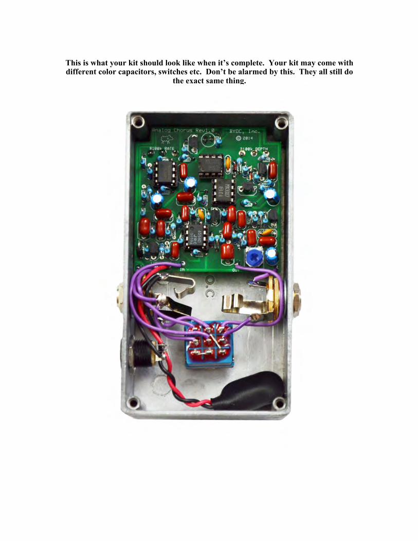
This is what your kit should look like when it’s complete. Your kit may come with different color capacitors, switches etc. Don’t be alarmed by this. They all still do
the exact same thing.

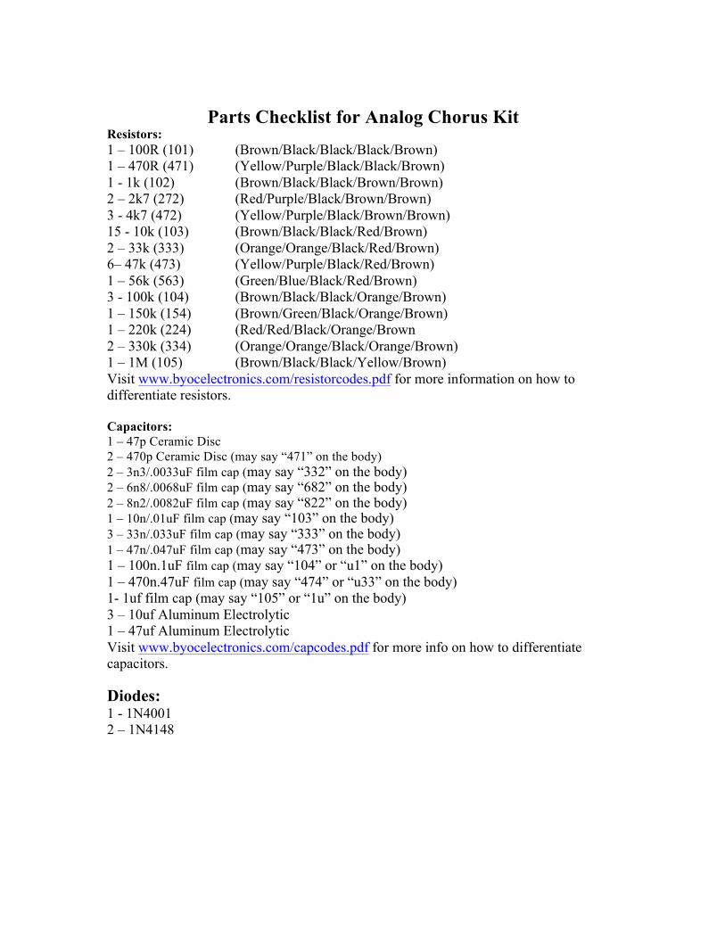
Parts Checklist for Analog Chorus Kit
Resistors: 1 – 100R (101) (Brown/Black/Black/Black/Brown) 1 – 470R (471) (Yellow/Purple/Black/Black/Brown) 1 - 1k (102) (Brown/Black/Black/Brown/Brown) 2 – 2k7 (272) (Red/Purple/Black/Brown/Brown) 3 - 4k7 (472) (Yellow/Purple/Black/Brown/Brown) 15 - 10k (103) (Brown/Black/Black/Red/Brown) 2 – 33k (333) (Orange/Orange/Black/Red/Brown) 6– 47k (473) (Yellow/Purple/Black/Red/Brown) 1 – 56k (563) (Green/Blue/Black/Red/Brown) 3 - 100k (104) (Brown/Black/Black/Orange/Brown) 1 – 150k (154) (Brown/Green/Black/Orange/Brown) 1 – 220k (224) (Red/Red/Black/Orange/Brown 2 – 330k (334) (Orange/Orange/Black/Orange/Brown) 1 – 1M (105) (Brown/Black/Black/Yellow/Brown) Visit www.byocelectronics.com/resistorcodes.pdf for more information on how to differentiate resistors. Capacitors: 1 – 47p Ceramic Disc 2 – 470p Ceramic Disc (may say “471” on the body) 2 – 3n3/.0033uF film cap (may say “332” on the body) 2 – 6n8/.0068uF film cap (may say “682” on the body) 2 – 8n2/.0082uF film cap (may say “822” on the body) 1 – 10n/.01uF film cap (may say “103” on the body) 3 – 33n/.033uF film cap (may say “333” on the body) 1 – 47n/.047uF film cap (may say “473” on the body) 1 – 100n.1uF film cap (may say “104” or “u1” on the body) 1 – 470n.47uF film cap (may say “474” or “u33” on the body) 1- 1uf film cap (may say “105” or “1u” on the body) 3 – 10uf Aluminum Electrolytic 1 – 47uf Aluminum Electrolytic Visit www.byocelectronics.com/capcodes.pdf for more info on how to differentiate capacitors. Diodes: 1 - 1N4001 2 – 1N4148
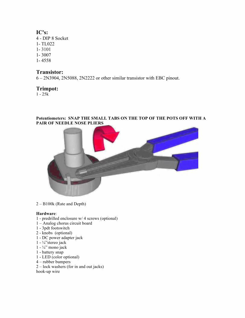
IC's: 4 - DIP 8 Socket 1- TL022 1- 3101 1- 3007 1- 4558 Transistor: 6 – 2N3904, 2N5088, 2N2222 or other similar transistor with EBC pinout. Trimpot: 1 - 25k Potentiometers: SNAP THE SMALL TABS ON THE TOP OF THE POTS OFF WITH A PAIR OF NEEDLE NOSE PLIERS
2 – B100k (Rate and Depth) Hardware: 1 - predrilled enclosure w/ 4 screws (optional) 1 – Analog chorus circuit board 1 - 3pdt footswitch 2 - knobs (optional) 1 - DC power adapter jack 1 - ¼”stereo jack 1 - ¼” mono jack 1 - battery snap 1 - LED (color optional) 4 – rubber bumpers 2 – lock washers (for in and out jacks) hook-up wire
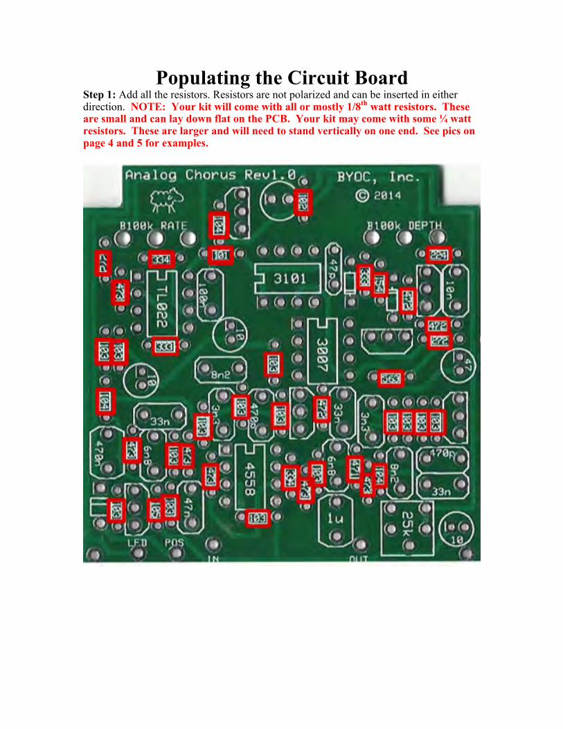
Populating the Circuit Board Step 1: Add all the resistors. Resistors are not polarized and can be inserted in either direction. NOTE: Your kit will come with all or mostly 1/8th watt resistors. These are small and can lay down flat on the PCB. Your kit may come with some ¼ watt resistors. These are larger and will need to stand vertically on one end. See pics on page 4 and 5 for examples.
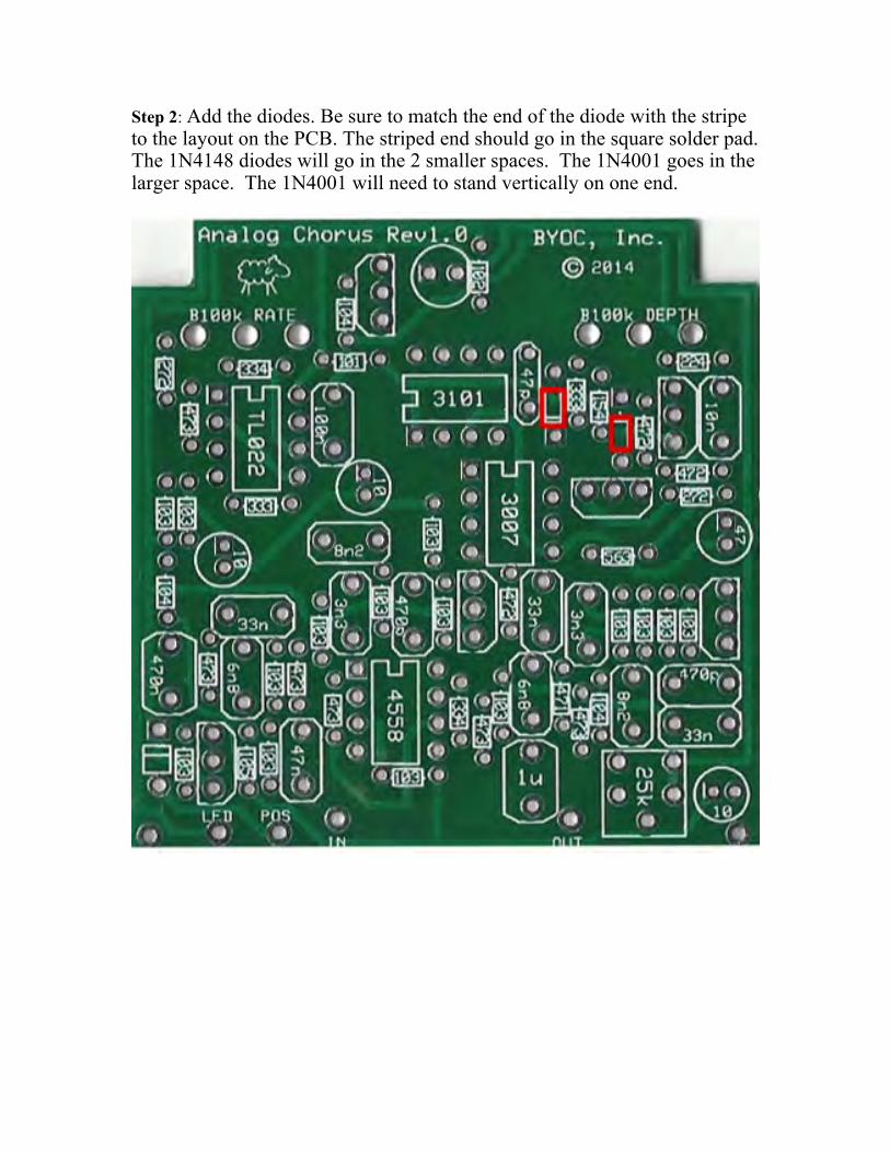
Step 2: Add the diodes. Be sure to match the end of the diode with the stripe to the layout on the PCB. The striped end should go in the square solder pad. The 1N4148 diodes will go in the 2 smaller spaces. The 1N4001 goes in the larger space. The 1N4001 will need to stand vertically on one end.
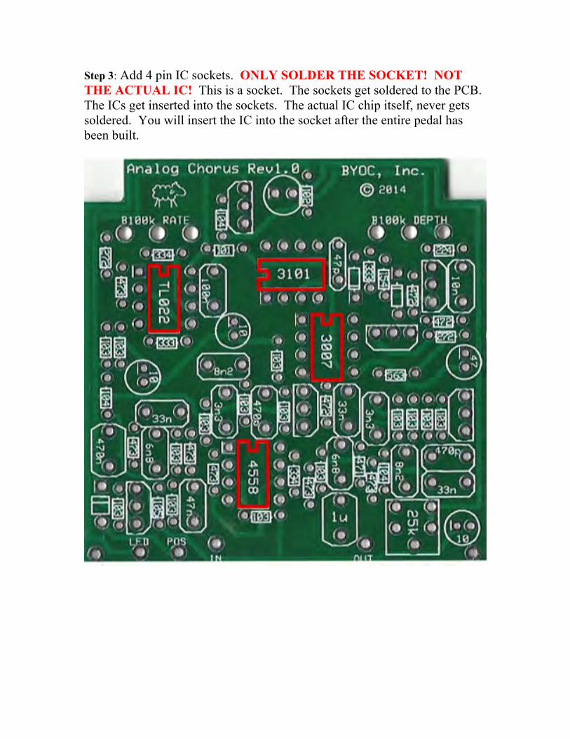
Step 3: Add 4 pin IC sockets. ONLY SOLDER THE SOCKET! NOT THE ACTUAL IC! This is a socket. The sockets get soldered to the PCB. The ICs get inserted into the sockets. The actual IC chip itself, never gets soldered. You will insert the IC into the socket after the entire pedal has been built.

Step 4: Add the transistors. Orient them so that the flat side matches up with the flat side on the PCB layout.

Step 5: The 1N4001 goes in the larger space. The 1N4001 will need to stand vertically on one end.

Step 6: Add the 25k Trim pot. Note that there are 5 holes on the PCB, but only 3 leads on the actual trimpot. Please do not let this confuse you. This is so that the PCB can accommodate a variety of trimpots. There should only be one way to fit the trimpot into the PCB. You do not need to bend the leads to make it fit (unless the leads were bent in shipping). You will need to adjust the trimpot when you are finished building the pedal. It controls the circuit’s bias voltage. You start by setting the trimpot at the middle of its rotation or “noon”. This will get you started and should definitely produce a chorus sound when you plug in for the first time. You fine tune the trimpot by strumming or plucking as hard as you can and dialing the trim pot till you get the least amount of distortion. If you have a guitar with hotter pickups, you should use it for this step.
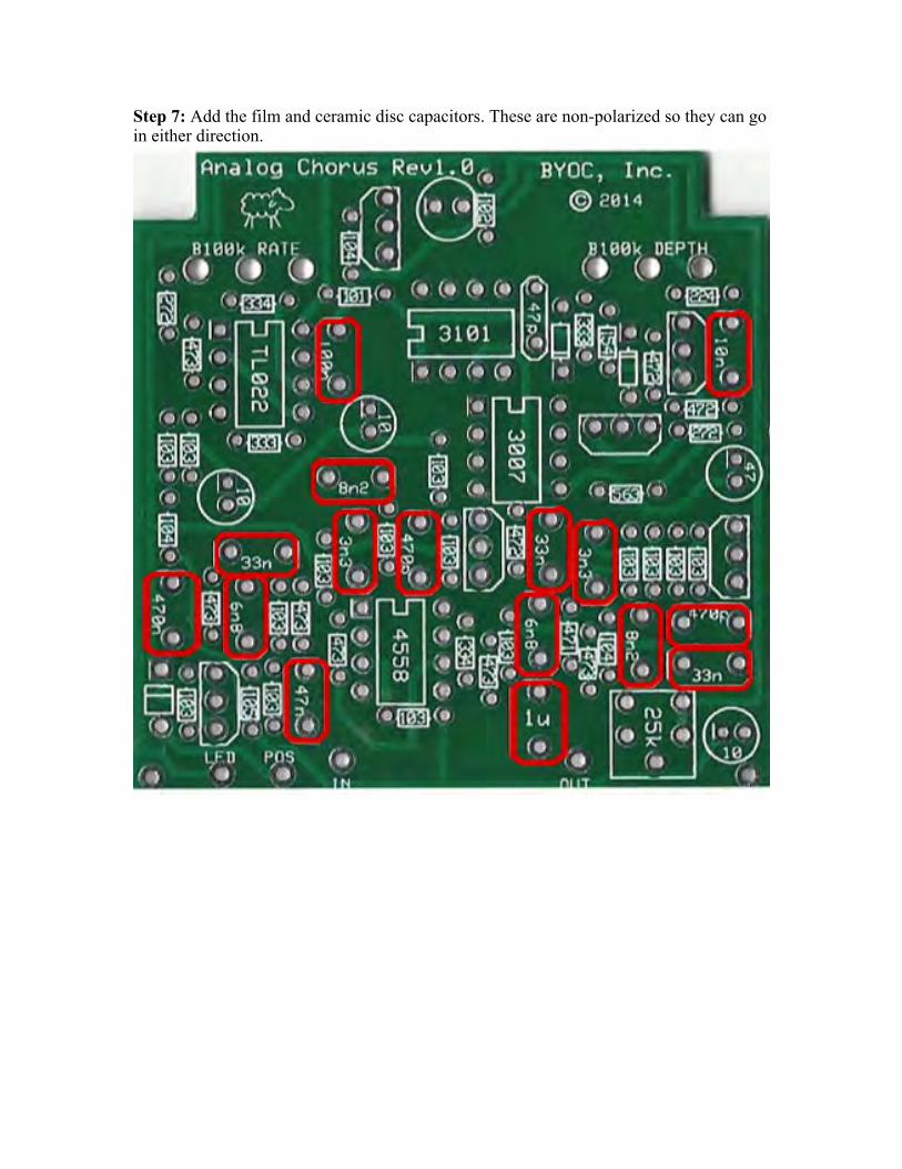
Step 7: Add the film and ceramic disc capacitors. These are non-polarized so they can go in either direction.

Step 8: Add the aluminum electrolytic capacitors. These ARE polarized, meaning there is a positive and negative end. The positive side will have a longer lead and goes in the square solder pad. The negative side will have a shorter lead and a stripe running along the body of the cap, and goes in the round solder pad.

At this point your board should look like this:
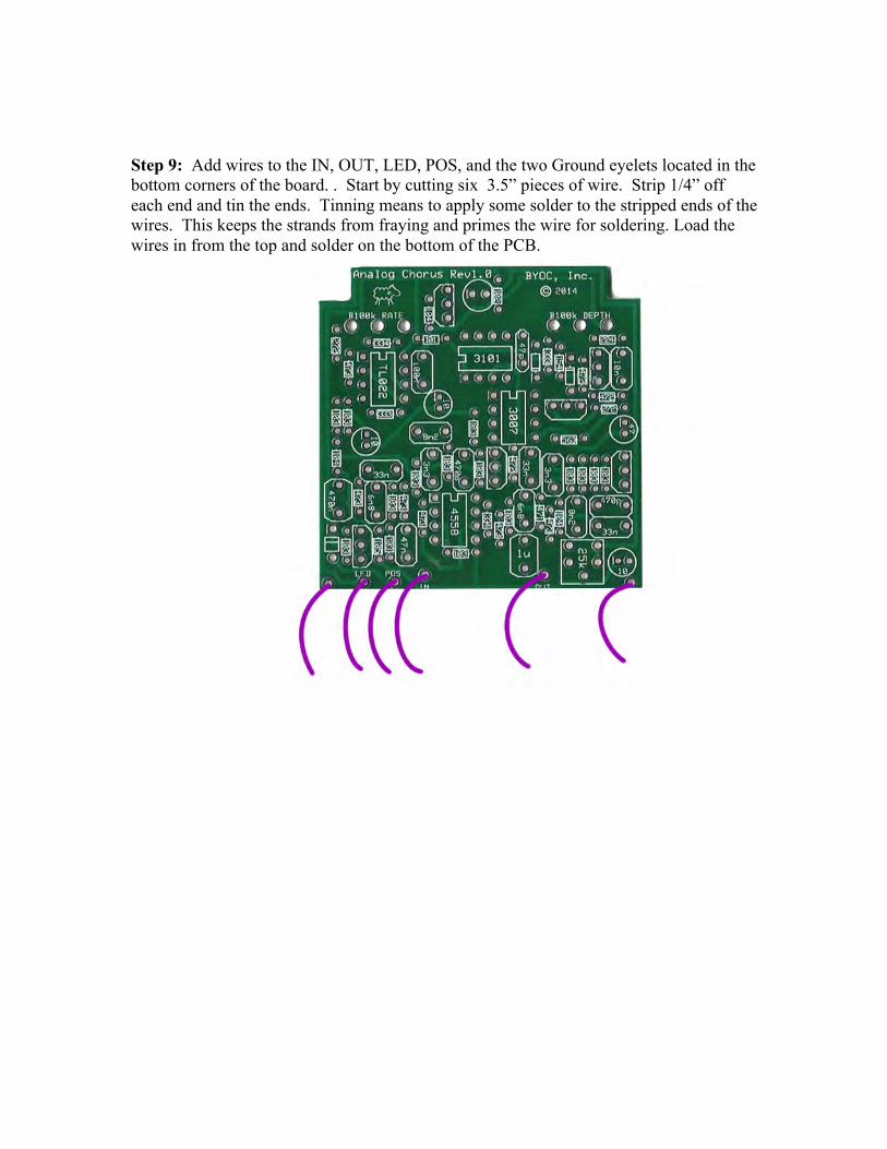
Step 9: Add wires to the IN, OUT, LED, POS, and the two Ground eyelets located in the bottom corners of the board. . Start by cutting six 3.5” pieces of wire. Strip 1/4” off each end and tin the ends. Tinning means to apply some solder to the stripped ends of the wires. This keeps the strands from fraying and primes the wire for soldering. Load the wires in from the top and solder on the bottom of the PCB.
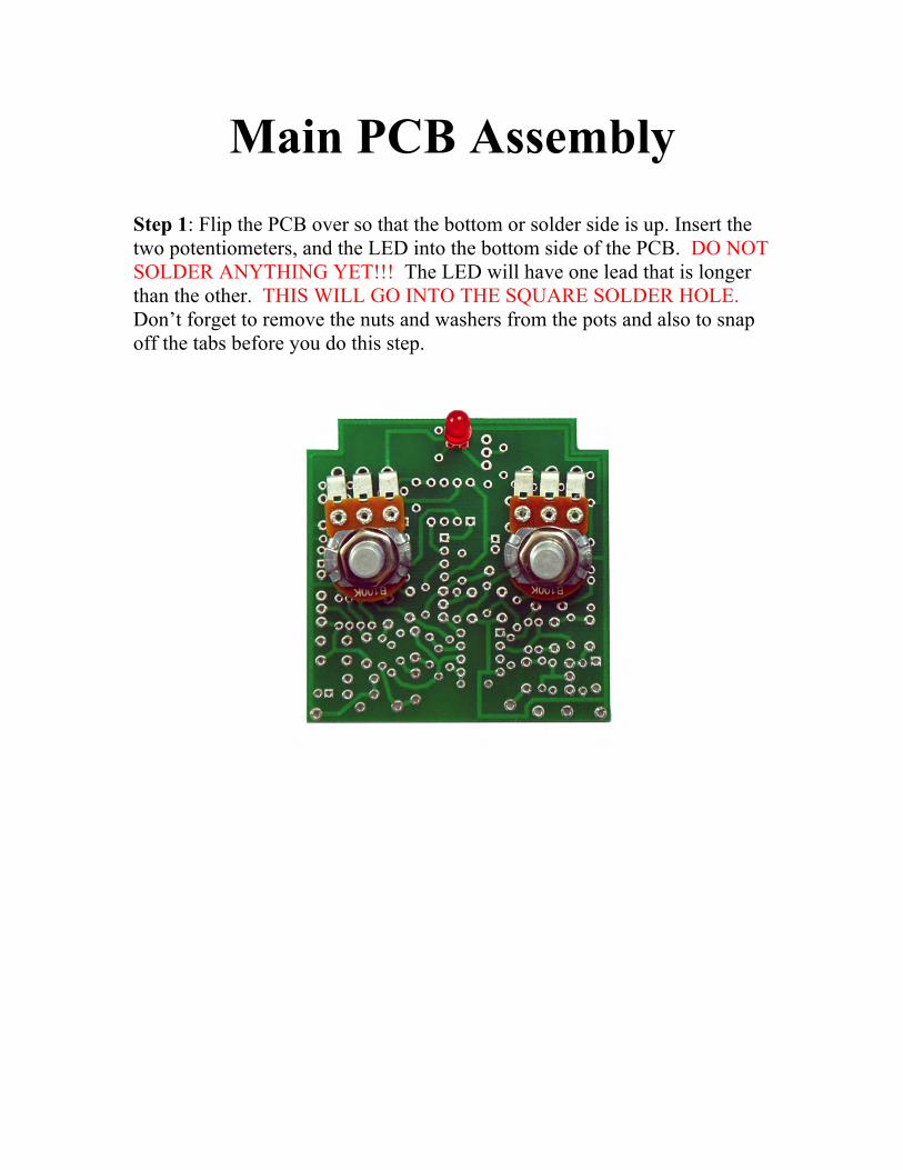
Main PCB Assembly
Step 1: Flip the PCB over so that the bottom or solder side is up. Insert the two potentiometers, and the LED into the bottom side of the PCB. DO NOT SOLDER ANYTHING YET!!! The LED will have one lead that is longer than the other. THIS WILL GO INTO THE SQUARE SOLDER HOLE. Don’t forget to remove the nuts and washers from the pots and also to snap off the tabs before you do this step.
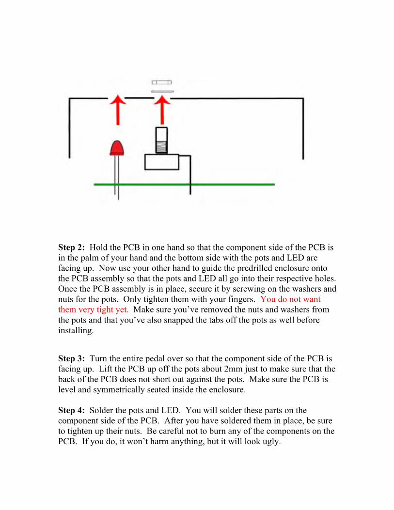
Step 2: Hold the PCB in one hand so that the component side of the PCB is in the palm of your hand and the bottom side with the pots and LED are facing up. Now use your other hand to guide the predrilled enclosure onto the PCB assembly so that the pots and LED all go into their respective holes. Once the PCB assembly is in place, secure it by screwing on the washers and nuts for the pots. Only tighten them with your fingers. You do not want them very tight yet. Make sure you’ve removed the nuts and washers from the pots and that you’ve also snapped the tabs off the pots as well before installing. Step 3: Turn the entire pedal over so that the component side of the PCB is facing up. Lift the PCB up off the pots about 2mm just to make sure that the back of the PCB does not short out against the pots. Make sure the PCB is level and symmetrically seated inside the enclosure. Step 4: Solder the pots and LED. You will solder these parts on the component side of the PCB. After you have soldered them in place, be sure to tighten up their nuts. Be careful not to burn any of the components on the PCB. If you do, it won’t harm anything, but it will look ugly.

Wiring
Step 1: Mount the DC adapter jack to the enclosure. Your kit may come
with either an external thread or internal thread. Don’t get confused by this. They still function exactly the same. You just thread the external nut on the
outside and the internal nut on the inside.

Stereo (Input) Jack Mono (Output) Jack
Step 2: Install the 1/4” jacks to the enclosure. The stereo IN jack mounts
on the same side as the DC adapter jack.

Step 3: Wire the “power section” of the pedal according to the diagram below. You should already have a wire connected to the POS eyelet of the PCB. Connect the other end of this wire to the sleeve terminal of the DC adapter jack. Connect the red battery wire to the battery terminal of the DC adapter jack. Connect one end of a 3” piece of wire (strip and tin both ends first) to the tip of the DC adapter jack.
Lastly, you’ll want to insert the stripped and tinned ends of both the black battery snap wire and the other end of the wire you just connected to the tip of the DC adapter jack into the RING of the IN jack. It will be much easier if you solder these wires to the RING together at the same time. That’s why we saved it for last in this step.
SUGGESTION: The battery snap wire will be longer than you need. You might want to trim it so it’s not so long. It comes pre-stripped and tinned, so you’ll need to redo that part. Also, if you want it to look pretty by twisting the battery snap wires, you’ll need to make the red wire shorter than the black wire. This isn’t difficult, but will require you to use your best judgment in approximating how much shorter to make the red wire. You want is so that when you pull on the untwisted battery snap wire, both the red and black wires are equally taut.
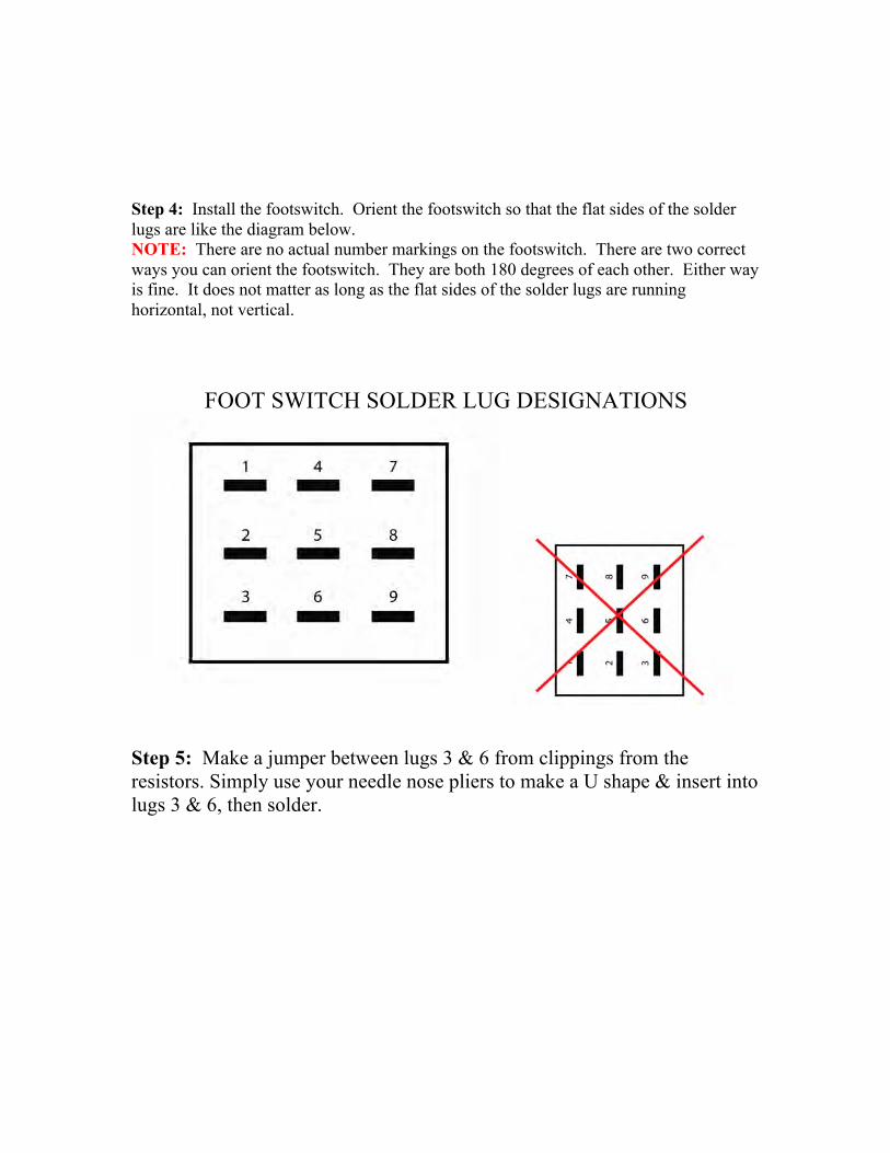
Step 4: Install the footswitch. Orient the footswitch so that the flat sides of the solder lugs are like the diagram below. NOTE: There are no actual number markings on the footswitch. There are two correct ways you can orient the footswitch. They are both 180 degrees of each other. Either way is fine. It does not matter as long as the flat sides of the solder lugs are running horizontal, not vertical.
FOOT SWITCH SOLDER LUG DESIGNATIONS
Step 5: Make a jumper between lugs 3 & 6 from clippings from the resistors. Simply use your needle nose pliers to make a U shape & insert into lugs 3 & 6, then solder.

Step 6: Connect a 4” wire to LUG 4 that also jumpers to LUG9. Strip about 1” off one end. Make sure there is enough insulated wire to make the connection to the TIP of the IN jack. Carefully tin the stripped end. You may want to twist the wire strands together tightly before tinning. Thread the stripped end through LUGs 4 and 9. This can be a little tricky. If this part is too frustrating for you, you can just run a separate wire to connect LUGs 4 and 9. Just be sure to solder the two wires at LUG 4 at the same time so you only need to make one solder joint.
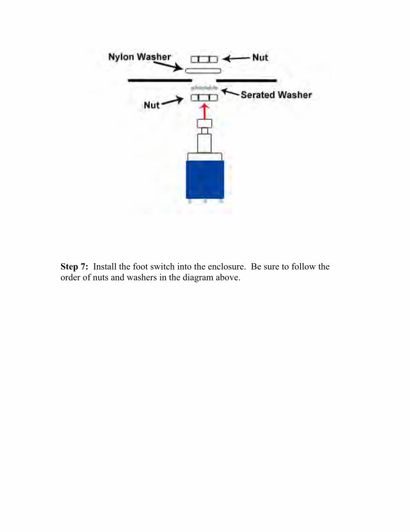
Step 7: Install the foot switch into the enclosure. Be sure to follow the order of nuts and washers in the diagram above.
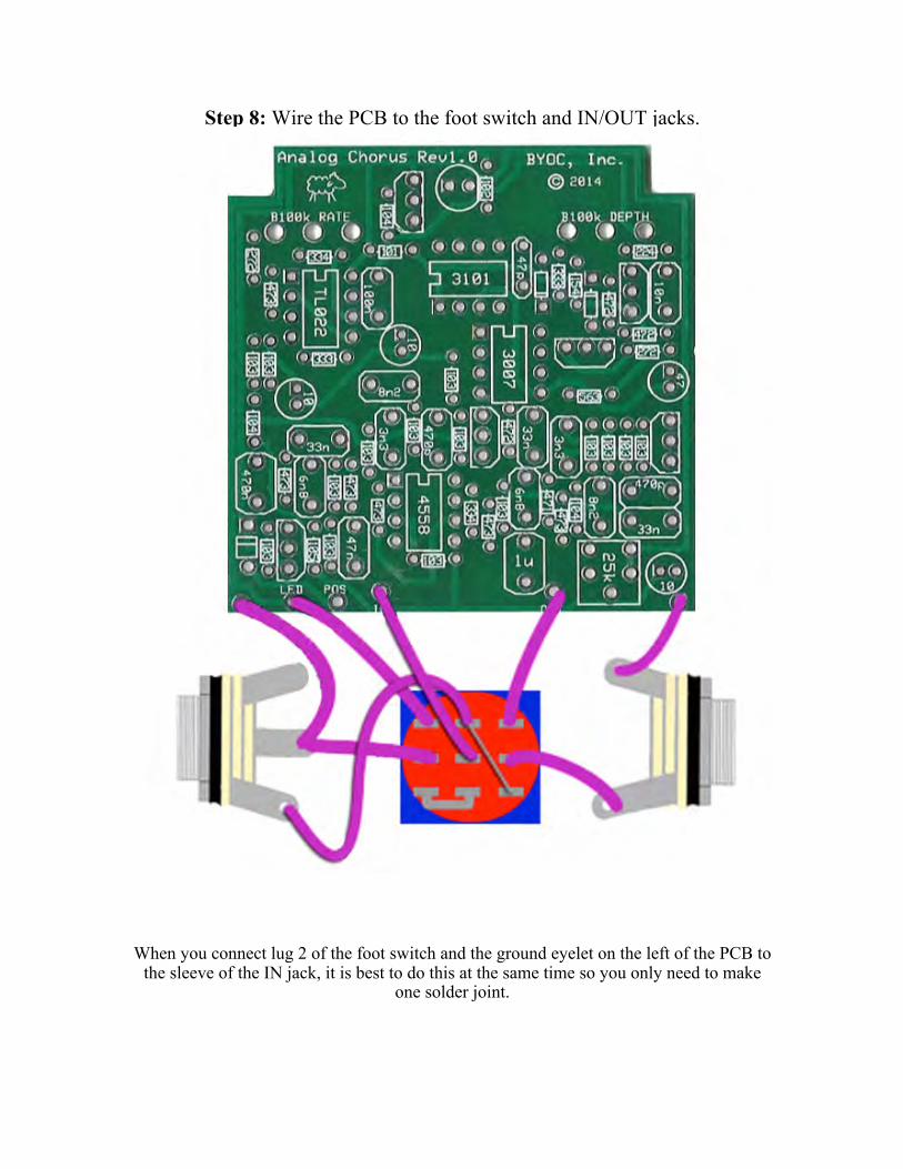
Step 8: Wire the PCB to the foot switch and IN/OUT jacks.
When you connect lug 2 of the foot switch and the ground eyelet on the left of the PCB to the sleeve of the IN jack, it is best to do this at the same time so you only need to make
one solder joint.


Installing IC/Finish up
Don't forget to adjust the trimpot, add the knobs, put the cover on the enclosure, and apply the bumpers to the cover.

Operating Overview
Depth: Controls the intensity of the chorus effect. Rate: Controls the speed of the chorus effect. Power supply: 9V battery or 2.1mm negative tip. 9V ONLY!!!! Current Draw: 12.5mA Input Impedance: 1M ohms Output Impedance: 100k ohms

For hi-res schematic visit http://www.byocelctronics.com/analogchorusschematic.pdf

Please visit
http://byocelectronics.com/board for any technical support
copyright 2014 BYOC, Inc.


![[chorus] Amen Amen Amen [end Chorus]](https://img.pdfslide.net/doc/110x75/56815dc0550346895dcbead0/chorus-amen-amen-amen-end-chorus.jpg)