Embed Size (px)
Citation preview

Building a Replica Prop
Dr. Horrible’s Stun Ray Rifle
By: Jeff Clark & Jessica Lynn Find me on Tumblr, The RPF & cosplay.com: JessicaChicGeek

Dr. Horrible’s Stun Ray Rifle Replica Prop Build
Page 1 of 44
Figure 1 – Dr. Horrible’s Stun Ray Rifle replica from the Replica Prop Forum.
Figure 2 – Firefly Sonic Rifle from the Firefly Props site
History and background of the Stun Ray rifle and predecessor props:
At the beginning of this project research was conducted to discover prior efforts to build a prop duplicate of the Dr. Horrible Stun Ray Rifle. This work also included efforts to find historic information on the design and operation of the Stun Ray Rifle. It’s disappointing that the best source of information on the original Stun Ray Rifle prop are the videos on the Sing-Along Wiki. This severely limits resolution and clarity needed to build a faithful replica. The most useful results of this effort are presented here. A post from the Replica Prop Forum provides detailed step by step descriptions and photos showing a build of the Dr. Horrible's Stun Ray Rifle. This post provided many great ideas and references.
Photos of the Firefly Sonic Rifle on the Firefly Props site were extremely helpful because of their high resolution and for providing many oblique views that were critical for establishing feature depth.

Dr. Horrible’s Stun Ray Rifle Replica Prop Build
Page 2 of 44
Figure 4 – Dr. Horrible’s Stun Ray Rifle replica presented in this build documentation.
Prop build methods described in Volpin Props site post N7 Rifle, Mass Effect 3 Assault Rifle provide detailed step by step descriptions and photos. The Props and Replica Design by Harrison Krix site is the best example found for design concepts and replica prop build methods. The mature designs and excellent craftsmanship presented on the site were of immense help in developing the Dr. Horrible Stun Ray Rifle build presented in this document. The Dr. Horrible Stun Ray Rifle replica discussed here was constructed in the first quarter of 2014. A 8” Jet lathe and a home built CNC mill based on the Sieg X2 milling machine were used to make most of the details used in the construction.
Figure 3 – Mass Effect 3, N7 Assault Rifle post on VolpinProps site.

Dr. Horrible’s Stun Ray Rifle Replica Prop Build
Page 3 of 44
History and background of the Stun Ray rifle and predecessor props:
The earliest Stun Ray rifle predecessor prop originated in the film ‘The 6th Day’, released in October 2000, starring Arnold Schwarzenegger as Adam Gibson. The 6th Day guns, referred to as the Foosh rifle and pistol, were unique and extraordinary. The Foosh pistol and rifle are some of the most unusual screen weapons ever developed since the Logan's Run Sandman gun and Blade Runner Rick Deckard blaster. Derivations of the 6th Day guns, the Sonic Rifle in the TV Series ‘Firefly’ and the Stun Ray Rifle from ‘Dr. Horrible’s Sing-Along Blog’, were produced in the style of stunt copies. They were molded then cast and finished to present a good appearance but without focus on durability or function. Background of the 6th Day Foosh guns:
The 6th Day guns were created by the now defunct Applied Effects LLC. Applied Effects were also responsible for the guns in the 2004 film ‘Van Helsing’, props for 2002 film ‘Minority Report’ as well as the TV Series ‘Firefly’. Serenity, the original two-hour Firefly pilot episode aired December 20, 2002. The Sonic Rifle used in Firefly made its debut in the episode titled ‘Ariel’. The Foosh gun designs were developed using 3D CAD Design Software SolidWorks. The completed CAD files were used to create most of the patterns for the guns, which were generated on several different rapid prototyping machines. The prototype patterns, which were produced on a 3D wax printer, were then sent to a foundry and were used to create molds from which aluminum and bronze parts were cast for the final working guns. A lot of handwork went into every weapon. A good deal of effort was required to fit the gas system and electronics into each gun, as all of the parts fit very closely together on the exterior of the prop. Plastic parts on the prop were cast in black-tinted resin and flexible rubber so that they would not scratch. All of the metal parts were powder-coated before final assembly. The effects house was attempting to create a tough finish that would not be easily damaged during filming.
Figure 5 – The 6th Day Foosh Rifle. The SDCCD on the side of the rifle stands for Super Duper Charged Couple Device.
Dr. Horrible’s Stun Ray Rifle Replica Prop Build
Page 4 of 44
Operation of the 6th Day Foosh guns:
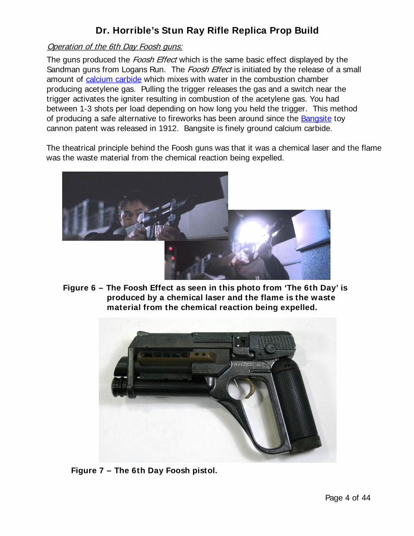
The guns produced the Foosh Effect which is the same basic effect displayed by the Sandman guns from Logans Run. The Foosh Effect is initiated by the release of a small amount of calcium carbide which mixes with water in the combustion chamber producing acetylene gas. Pulling the trigger releases the gas and a switch near the trigger activates the igniter resulting in combustion of the acetylene gas. You had between 1-3 shots per load depending on how long you held the trigger. This method of producing a safe alternative to fireworks has been around since the Bangsite toy cannon patent was released in 1912. Bangsite is finely ground calcium carbide. The theatrical principle behind the Foosh guns was that it was a chemical laser and the flame was the waste material from the chemical reaction being expelled.
Figure 6 – The Foosh Effect as seen in this photo from ‘The 6th Day’ is produced by a chemical laser and the flame is the waste material from the chemical reaction being expelled.
Figure 7 – The 6th Day Foosh pistol.

Dr. Horrible’s Stun Ray Rifle Replica Prop Build
Page 5 of 44
Figure 8 – The Firefly Sonic Rifle.
Background of the Firefly Sonic Rifle:
The Firefly Sonic Rifle was also created by Applied Effects LLC. Serenity, the original two-hour Firefly pilot episode aired December 20, 2002. The Sonic Rifle used in Firefly made its debut later in the episode titled ‘Ariel’. Operation of the Firefly Sonic Rifle:
The Sonic Rifle was a non-lethal weapon usually used by law enforcement, which emitted a highly-focused, low-pitched sound wave with enough force to drive a relatively large man to the ground. One benefit of the weapon aside from its lack of lethality was the reduced chance of property damage on the Core worlds, since the weapon seemed to have no adverse effects on non-living objects. Background of the Dr. Horrible Stun Ray gun:
The Dr. Horrible Stun Ray Rifle added a telescopic sight to the Firefly Sonic Rifle and was held upside-down. The Stun Ray Rifle was then transformed into the Death Ray Rifle by Dr. Horrible. Dr. Horrible created the Death Ray Rifle from a modified Stun Ray, in an event which marked the beginning of his descent into evil. The Death Ray, was a ray gun intended to kill people, using short red blasts. Dr. Horrible fired it several times successfully in the air to frighten his audience at the unveiling of a statue of Captain Hammer. It was forcibly taken from Dr. Horrible by Captain Hammer who turned it on him. In the process of taking the Death Ray it was damaged and when Captain Hammer tried to kill Dr. Horrible with it, it malfunctioned, exploding into pieces. Operation of the Dr. Horrible gun:
The Stun Ray Rifle was powered by Wonderflonium which is an unstable power source and is something you definitely do not want to drop! Wonderflonium, is available in a convenient suitcase size package.

Dr. Horrible’s Stun Ray Rifle Replica Prop Build
Page 6 of 44
Build Documentation of the Stun Ray Rifle Replica Prop:
The Stun Ray rifle replica was recently built by my granddaughter and I. Her passion for costume creation lead to an intense interest in Comic-Con and Cosplay. So in early 2014 she suggested that we build this replica prop with the hope that it might be ready for the Arizona Comic Con in June 2014. Process for production of the Stun Ray detail parts:
An 8” Jet lathe and a home built CNC milling machine based on the Sieg X2 were used to make most of the details used in the construction. Outlines for the details were generated from photos of the Firefly Sonic Rifle on the Firefly Props site by tracing the shape using Deneba Canvas. The Canvas outlines were saved in DXF format and then opened in AutoCAD and cleaned up to assure a precise fit of the mating details. When design of the detail parts was complete in AutoCAD the details were again saved in DXF format and then opened in CamBam in order to generate the G-code files required by the CNC milling machine. CamBam is a CAM, Computer Aided Manufacturing, program and outputs G-code as EIA compliant RS-274D files required by Mach3. Mach3 is the control software used by the CNC milling machine.
Figure 9 – Outlines for all the details are shown assembled on a 1 inch grid. The small circle within a circle features are holes that are used for alignment when stacking the details. Steel pins are inserted into the holes to keep everything in place during assembly.

Dr. Horrible’s Stun Ray Rifle Replica Prop Build
Page 7 of 44
Electronics used in the Stun Ray replica build:
The USB Battery Pack, SparkFun PRT-11359, control board was removed and used to provide a 5VDC step-up power supply that will source 700mA as well as a charger for the 3.7V LiPo Battery. The USB USB 2.0 Female Type A power output connector was removed from the board and replaced with soldered on wires. The 2000mAh battery was also replaced with a 3000mAh LiPo Battery, MH21251, from a Sony TF-DVD7050 DVD player.
Figure 10 – Power Control Board and Battery inside the SparkFun USB Battery Pack - PRT-11359
Figure 11 – Power Control Board removed from a SparkFun 2000mAh Lithium Ion Polymer USB Battery Pack - PRT-11359
Power Control Board On
5V Buss Power Out Connection
3.7V LiPo Battery Input Connection
Power Control Board Status LED’s
USB 2.0 Micro Female Type B Battery Charge Port
USB Power Output Connector Removed

Dr. Horrible’s Stun Ray Rifle Replica Prop Build
Page 8 of 44
Figure 13 – Power Control Board and a few of the NeoPixel RGB LED Displays used on the replica.
3.7V LiPo Battery Input
Power Control Board
6 and 4 Pixel NeoPixel RGB LED’s
3.7V LiPo Battery Buss
Figure 12 – USB Charge Port on the Power Control Board and control buttons for the 5V and 3.7V power busses. The power control board ON button and status LED’s were extended through the right side cover.
USB 2.0 Micro Female Type B Battery Charge Port
5V Buss On/Off
Power Control Board On
Power Control Board Status LED 3.7V LiPo Battery Disconnect

Dr. Horrible’s Stun Ray Rifle Replica Prop Build
Page 9 of 44
Figure 14 – OSEPP Pro Arduino processor board and associated connections. Documentation is not provided here since the subject is extensively covered on the internet.
FTDI serial breakout board connector
5V Buss Power from the
Power Control Board
Automatic loading circuit
Figure 15 – Breakout board cable connects OSEPP Pro Arduino processor board to FTDI serial to USB board.
FTDI serial board cable connector
3.7V Buss connector board
4 and 6 pixel NeoPixel RGB LED’s
The emblem is removed to access the FTDI serial
programming cable connector
The USB to serial board is external to the Pro version of the Arduino and is only required for software development. The Arduino Pro board is intended for permanent installation in applications where there will be no need for software development. The Arduino Pro has a six pin header which can be connected to a Future Technology Devices International (FTDI) FT232RL cable to provide USB power and communication to the board during application development.

Dr. Horrible’s Stun Ray Rifle Replica Prop Build
Page 10 of 44
Connects the 30N06L MOSFET to the 5V buss
30N06L MOSFET
Connects the 3 Luxeon Rebel High Power red LED's to the 30N06L MOSFET
Connects 30N06L MOSFET base to Arduino pin 7 Figure 16 – 30N6L MOSFET and associated power and control connections.
The 3 Luxeon Rebel High Power red LEDs (LXML-PD01-0040) in the barrel produce 75 Lumens of light each at 700mA. They are wired in parallel and draw 2100mA combined. This high current demand is why we drive the LEDs through a 30N06L MOSFET directly from the 5V supply, the MOSFET can handle up to 60 V at 30A. Arduino digital pins can only source about 40mA and the Arduino board 5V linear regulator can only provide about 500mA reliably. The MOSFET lead G, On/Off control, has a green wire terminated in a female plug that connects to Arduino pin 7. The 10KΩ resistor across the G and S leads is a safety feature that assures the MOSFET stays off until the Arduino pulls the pin up to 5V.
Figure 17 – Schematic of the 3 Luxeon Rebel High Power red LED's connected in series to an Arduino processor board through a 30N6L MOSFET.

Dr. Horrible’s Stun Ray Rifle Replica Prop Build
Page 11 of 44
Heat sink pad on bottom of LED’s is soldered to a Copper heat sink
Figure 18 – Luxeon Rebel High Power red LED's (LXML-PD01-0040) are located in the barrel, wired in parallel and soldered to a copper heat sink.
Luxeon Rebel High Power red LED's
Grooves in Copper Heat Sink for wire clearance Kapton polyimide Tape
½” Diameter Copper Heat Sink Heat sink pad on bottom of LED
Luxeon LED's installed and powered
Figure 19 – Luxeon LED's and Heat Sink assembly shown approximately where they are fitted when installed toward the front of the turned Aluminum barrel.

Dr. Horrible’s Stun Ray Rifle Replica Prop Build
Page 12 of 44
Figure 21 – One of the speakers about to be mounted into the mating hole in the gun body.
Figure 20 – The speakers are 8Ω 1Watt and are mounted in holes on both sides of the gun body. The speaker housings align with the outside diameter of the speakers. The housing ends are covered with 0.005 inch thick 304 SS sheet that has been perforated with 0.006 inch diameter holes located on 0.01 inch centers.

Dr. Horrible’s Stun Ray Rifle Replica Prop Build
Page 13 of 44
Figure 22 – An Adafruit WavShield was used to add sound to the prop. Wave (.wav) format sound files are stored on the SD card and are played by the Arduino control software enabling the prop to take on a real personality.
Figure 23 – The telescopic sight is fitted with a 5mW 650nm Red Laser diode crosshair, LHM1230. The crosshair Laser draws 13mA and is driven directly by the Arduino, it’s connected to digital pin 6.
The Laser diode crosshair, LHM1230, is installed in the front part of the telescopic sight

Dr. Horrible’s Stun Ray Rifle Replica Prop Build
Page 14 of 44
Figure 25 – This momentary contact switch is used to initiate a software based menu. The switch and a NeoPixel LED are
underneath the clear Acrylic button.
Figure 24 – The trigger and microswitch that it actuates, there’s a small coil spring inside the black plastic tube that returns the trigger when it’s released.

Dr. Horrible’s Stun Ray Rifle Replica Prop Build
Page 15 of 44
Figure 27 – On the left is a close-up of the WS2812 SMD and on the right is the integral WS2811 Controller.
A Short Course on the Intelligent RGB LEDs used on the Stun Ray gun:
40 Adafruit NeoPixel WS2812 RGB LEDs were used in the Stun Ray replica build. NeoPixel RGB LEDs are chainable; you connect the output pin of the first one to the input pin of the next one in the chain. They use only one Arduino pin to control all 40. Each WS2812 or pixel, is addressable because each pixel has a WS2811 Controller chip is inside. The WS2812 LED chips sometimes include the term “SMD 5050” because the dimensions of the Surface Mountable Device (SMD) are 5.0mm x 5.0mm. Pixels have 3 LED diodes in one housing along with a WS2811 Controller. Each pixel has a ~18 mA constant current drive so the color will be very consistent even if the voltage varies. The chain has a single serial data input line with a very timing-specific protocol. Since the protocol is very sensitive to timing, it requires a real-time microcontroller like the Arduino. An Adafruit NeoPixel library for the Arduino supports the RGB LEDs. The whole chain of pixels is powered with 5VDC and no external choke resistors are required on the power circuit.
WS2811 Controller Chip
Superbright Blue LED
Superbright Green LED
Superbright Red LED
Figure 26 – NeoPixels are WS2812 Surface Mount Devices (SMD) that contain three Superbright LED’s with an Integrated WS2811 Controller that drives the LED’s as an RGB device.
WS2812 SMD 5050 RGB LED

Dr. Horrible’s Stun Ray Rifle Replica Prop Build
Page 16 of 44
Figure 28 – A single WS2812 RGB LED on a small Adafruit PCB. A total of 28 of these NeoPixel PCB’s were used on the gun.
Figure 29 – Comparison of the WS2812 RGB LED and the recently released WS2812B version. Beware, the WS2812B pin 1 isn’t the corner with the step in it!
Power requirements for the 40 pixels must also be accommodated. Each pixel draws up to 60 milliamps at maximum brightness white (red + green + blue all on at the same time). In actual use though, it’s rare for all pixels to be turned on at the same time much less all of them turned on to white. When mixing colors and displaying animations, the current draw will be much less. A reasonable estimate is about 20 mA per pixel, that’s 40 pixels × 20 mA = 800 mA minimum. All 40 pixels are wired as a single strand; this allows us to select any pixel color and pattern we want at the maximum refresh rate that the system can provide. NeoPixels receive data from a fixed-frequency 800 KHz serial data stream and each pixel requires 30 microseconds to be refreshed. After the last pixel’s worth of data is issued, the data stream must stop for at least 50 microseconds for the new colors to “latch.” For a strip of 40 pixels, that’s (40 * 30) + 50, or 1,250 microseconds to update all the pixels. The maximum rep rate is therefore 1,000,000 / 1,250 = 800 updates per second. At this rate the changing colors and patterns are a blur; this is good however because it means we have plenty of time for the processor to do other things like checking to see if the trigger or the button were pressed. To optimize the effect of colors and pixel patterns for our animation effects we will introduce delay as appropriate. Since each pixel passes the remainder of the data to the next pixel in the strand, if a pixel fails then all the downstream pixels will appear to be dead.

Dr. Horrible’s Stun Ray Rifle Replica Prop Build
Page 17 of 44
4 pixels in each tube, positioned in slots, these point up
4 pixels in each tube, positioned in slots, these point down
4 pixel and 6 pixel
rings
12 pixel ring
Single pixel and hemisphere push button
Single pixel hemisphere
Figure 30 – Locations of the 40 NeoPixels used in the Stun Ray replica.
The 40 NeoPixels used in the Stun Ray replica are located in the areas of the gun as shown in Figure 30.
• There are 4 pixels in each of the four tubes, two tubes on each side of the gun toward the front for a total of16.
• There are 4 pixel and 6 pixel rings that were constructed from individual Adafruit NeoPixel’s on a small PCB.
• There are 12 pixels in the Adafruit NeoPixel ring, these pixels on a PCB and are arranged in a circle with an 1.5" outer diameter.
• There are 2 pixels, 1 pixel under each of two Acrylic hemispheres, 1 on each side of the gun stock. The hemisphere on the right side also actuates a switch and is used to initiate a software based menu.

Dr. Horrible’s Stun Ray Rifle Replica Prop Build
Page 18 of 44
Idle current is consumed when the NeoPixel LEDs are off, each WS2811 controller chip consumes approximately 0.9 mA of current in the idle state. For battery powered LEDs, this current can easily drain the battery. A MOSFET transistor or such as the 30N06L used to control power to the Luxeon High Power LEDs may be needed to disconnect power from the LEDs, if the battery remains connected when the LEDs are not in use.
Adafruit 12 pixel ring
4 and 6 pixel rings
Figure 31 – Single Adafruit NeoPixel WS2812 RGB LED on a small PCB were used to build the 4 and 6 pixel rings. The 12 pixel NeoPixel ring is a PCB assembly from Adafruit.
Figure 32 – The 4 and 6 pixel rings are shown installed in the left side cover assembly.

Dr. Horrible’s Stun Ray Rifle Replica Prop Build
Page 19 of 44
Acrylic hemisphere used to actuate the switch
Figure 34 – A momentary contact switch is used to initiate a software based menu. A NeoPixel is also under the clear
Acrylic lens that serves as a button.
Adafruit PCB with WS2812 SMD
Momentary contact switch
Figure 33 – The 12 pixel NeoPixel ring PCB assembly from Adafruit is mounted in the left side cover assembly under a diffuser disk and a clear lens.

Dr. Horrible’s Stun Ray Rifle Replica Prop Build
Page 20 of 44
/* // The following definitions apply to the 40 pixel // NeoPixel strand used on the Stun Ray gun. int smallCircle[] = 0, 1, 2, 3; int mediumCircle[] = 4, 5, 6, 7, 8, 9; int topLeft[] = 10, 11, 12, 13; int bottomLeft[] = 14, 15, 16, 17; int topRight[] = 18, 19, 20, 21; int bottomRight[] = 22, 23, 24, 25; int largeCircle[] = 26, 27, 28, 29, 30, 31, 32, 33, 34, 35, 36, 37; int buttons[] = 38, 39; */
Dr. Horrible’s Stun Ray Rifle Replica Prop Build
Page 21 of 44
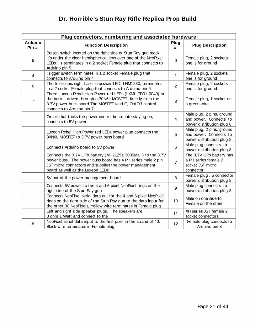
Plug connectors, numbering and associated hardware Arduino
Pin # Function Description Plug # Plug Description
5
Button switch located on the right side of Stun Ray gun stock, it’s under the clear hemispherical lens over one of the NeoPixel LEDs. It terminates in a 2 socket Female plug that connects to Arduino pin 5
0 Female plug, 2 sockets, one is for ground
4 Trigger switch terminates in a 2 socket Female plug that connects to Arduino pin 4 1 Female plug, 2 sockets,
one is for ground
6 The telescopic sight Laser crosshair LED, LHM1230, terminates in a 2 socket Female plug that connects to Arduino pin 6 2 Female plug, 2 sockets,
one is for ground
7
Three Luxeon Rebel High Power red LEDs (LXML-PD01-0040) in the barrel, driven through a 30N6L MOSFET directly from the 3.7V power buss board The MOSFET lead G, On/Off control connects to Arduino pin 7
3 Female plug, 1 socket on a green wire
Circuit that tricks the power control board into staying on, connects to 5V power 4
Male plug, 2 pins, ground and power. Connects to power distribution plug 8
Luxeon Rebel High Power red LEDs power plug connects the 30N6L MOSFET to 3.7V power buss board 5
Male plug, 2 pins, ground and power. Connects to power distribution plug 8
Connects Arduino board to 5V power 6 Male plug connects to power distribution plug 8
Connects the 3.7V LiPo battery (MH21251 3000MaH) to the 3.7V power buss. The power buss board has 4 PH series male 2 pin JST micro connectors and supplies the power management board as well as the Luxeon LEDs
7 The 3.7V LiPo battery has a PH series female 2 socket JST micro connector
5V out of the power management board 8 Female plug , 5 connector power distribution plug 8
Connects 5V power to the 4 and 6 pixel NeoPixel rings on the right side of the Stun Ray gun 9 Male plug connects to
power distribution plug 8
Connects NeoPixel serial data out for the 4 and 6 pixel NeoPixel rings on the right side of the Stun Ray gun to the data input for the other 30 NeoPixels, Yellow wire terminates in Female plug
10 Male on one side to Female on the other
Left and right side speaker plugs. The speakers are 8 ohm 1 Watt and connect to the 11 XH series JST female 2
socket connectors
8 NeoPixel serial data input to the first pixel in the strand of 40. Black wire terminates in Female plug. 12 Female plug connects to
Arduino pin 8

Dr. Horrible’s Stun Ray Rifle Replica Prop Build
Page 22 of 44
Firefly Sonic Rifle Emblem
Details traced from the Firefly Sonic Rifle photo
Figure 35 – The emblem pattern was then used to make a mold for casting the emblems that are used on both sides of the gun.
CamBam screen shot of the emblem details
Emblem details machined from high density fiberboard
Building the Hardw are for the Stun Ray replica build:
Building the Emblem:
The emblem which is located on both sides of the Firefly Sonic Rifle was traced from a photo using Deneba Canvas. The Canvas outlines were saved in DXF format and then opened in AutoCAD and cleaned up. The final AutoCAD details were again saved in DXF format and opened in CamBam to generate the G-code files required by the CNC milling machine control software, Mach3.

Dr. Horrible’s Stun Ray Rifle Replica Prop Build
Page 23 of 44
Angled sides on the emblem required that three pieces be machined and epoxied together to form the emblem pattern that was used to make the silicone rubber mold. The mold was used to cast polyester emblems that are located on the side covers on both sides of the gun. Gun Build in General:
All of the gun parts were made from MDF, Medium Density Fiberboard, of thicknesses that ranged from 0.060 inch to 0.750 inch. MDF is easy to find at lumber and hardware stores and it’s inexpensive. It’s easily machined without chipping and it retains very detailed features. MDF can be strengthened and moisture stabilized by soaking it in diluted polyurethane adhesive. Most polyurethane adhesives foam and expand as curing occurs, higher humidity will result in greater foaming. Foaming is a good thing most of the time because it fills in irregular and poorly fitting joints. Be cautious when construction includes interior details that can be rendered inoperative if the foaming glue gets inside. Elmers ELME9416 Polyurethane Glue was used in this project because of its predictable foaming behavior.
Foosh Pistol Emblem
Firefly Sonic Rifle Emblem
Casting of Replica Emblem
Silicone Mold of Replica Emblem
Replica Emblem Figure 36 – The emblems used on the Foosh Pistol and the Firefly Sonic Rifle are
the same as that on the Dr. Horrible Stun Ray rifle.

Dr. Horrible’s Stun Ray Rifle Replica Prop Build
Page 24 of 44
Building the Side Covers:
The side covers are mirror images except for the cylindrical features, a 2.0 inch diameter on the right cover and a 1.5 and 1.4 inch diameter on the left cover. These cylinders house NeoPixel RGB LED rings. ½ inch MDF is used on the lower half and ¾ inch thick MDF on the upper half on each side. A 1.50 inch through hole in the upper half of each cover provides a locator for the emblems. The upper and lower details are contoured prior to gluing the halves together.
Figure 37 – The side cover drawings are to scale shown on a of ¼ inch grid. The contoured and glued halves are blended using Squadron Products White Putty.

Dr. Horrible’s Stun Ray Rifle Replica Prop Build
Page 25 of 44
Figure 38 – Steps involved in making the side covers. Top - CNC machining the cylinders, Center – Gluing the cylinders, Bottom – Finished covers painted with Rust-Oleum 7220-830 Textured Black Enamel.

Dr. Horrible’s Stun Ray Rifle Replica Prop Build
Page 26 of 44
Building the Telescopic Sight:
The Firefly Sonic Rifle does not have a scope so the only choice for dimensions was to turn to the best available photo of Dr. Horrible’s Stun Ray rifle. The resolution and dimensional perspective in this video frame is as good as it gets. Other perspective views are either of poor resolution or blurred. The rifle scope was turned from a 2.75 inch diameter by 15 inch long piece of hardwood, a 0.40 inch diameter hole was bored through the center. A 5mW 650nm Red Laser diode crosshair is installed in the front part of the telescopic sight as shown in Figure 23. Figure 39 – The rifle scope drawing is to scale and shown on a 0.25 inch grid.

Dr. Horrible’s Stun Ray Rifle Replica Prop Build
Page 27 of 44
Figure 41 – The left and right side speaker housings, they are made from 0.75 inch thick MDF.
Building the Rifle Body Details:
Building the Slotted Barrel Cylinders and Speaker Housings:
There are 4 slotted cylindrical parts, 2 are on each side of the barrel at the front of the gun. Each slot is fitted with a single Adafruit NeoPixel WS2812 RGB LED on a small PCB, each cylinder gets 4 pixels, all 16 are then wired so that data is input in series. The slot that runs lengthwise inside the cylinder accommodates the LED PCBs as well as the wires for power and data.
Figure 40 – The 4 slotted cylindrical parts, 2 are on each side at the front of the gun, are fitted with LED’s. Each slot gets a single NeoPixel on a small Adafruit PCB.
The cylinders were machined from 0.75 inch thick MDF stock
Finished cylinders

Dr. Horrible’s Stun Ray Rifle Replica Prop Build
Page 28 of 44
Building the Stock Appliqués and Sideplates:
There are 4 appliqués and a three hole sideplate on each side of the stock, these are mirrored on the left and right side of the stock. Figure 43 – The Three Hole Sideplate drawing is to scale and shown on a ¼ inch
grid. The left and right side details are the same, two of these are required, they are made from ⅛ inch thick MDF.
Figure 42 – The stock appliqués drawing is to scale and shown on a 0.25 inch grid. The left and right side details are mirror images, only one set is shown, they are made from 0.060 inch thick MDF.

Dr. Horrible’s Stun Ray Rifle Replica Prop Build
Page 29 of 44
Figure 45 – The Forward Canister was turned on a lathe and was made from hard pine stock. The Forward Canister and the Barrel Socket are both embedded in the stock
Building the Turned Details that are Embedded in the Stock:
The Barrel Socket and Forward canister were turned on the lathe from hard pine. They are glued into the three sheets of ¼ inch thick MDF that are used to build the stock.
Figure 44 – The Barrel Socket was turned on a lathe and was made from hard pine stock. The center bore is a snug fit to the Aluminum barrel, approximately 0.710 inch diameter.
Dr. Horrible’s Stun Ray Rifle Replica Prop Build
Page 30 of 44
Building the Gun Body and Stock:
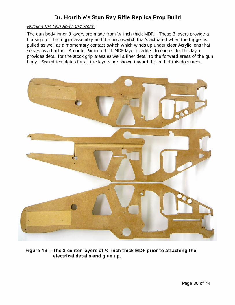
The gun body inner 3 layers are made from ¼ inch thick MDF. These 3 layers provide a housing for the trigger assembly and the microswitch that’s actuated when the trigger is pulled as well as a momentary contact switch which winds up under clear Acrylic lens that serves as a button. An outer ⅛ inch thick MDF layer is added to each side, this layer provides detail for the stock grip areas as well a finer detail to the forward areas of the gun body. Scaled templates for all the layers are shown toward the end of this document.
Figure 46 – The 3 center layers of ¼ inch thick MDF prior to attaching the electrical details and glue up.

Dr. Horrible’s Stun Ray Rifle Replica Prop Build
Page 31 of 44
Figure 47 – This view shows he trigger assembly and the microswitch that’s actuated when the trigger is pulled. The wire pair leading to the left connects to the momentary contact switch used to initiate a
software based menu. The yellow and blue wires going to the right connect to the Luxeon LED's in the barrel.
Figure 48 – A 3000mAh LiPo Battery, MH21251 from a Sony TF-DVD7050 DVD player, provides power to the gun. A NeoPixel LED and a momentary contact switch used to initiate a software based menu is shown to the lower right of the battery .

Dr. Horrible’s Stun Ray Rifle Replica Prop Build
Page 32 of 44
Figure 49 – Three stages of the gun body build. • The top view shows the 3 inner ¼ inch thick as well as the left and
right side ⅛ inch MDF outer layers following glue up. The left and right Butt pads, shown in Figure 50, were added after this stage.
• The center view shows the body assembly after blending using Squadron Products White Putty and painting with Rust-Oleum 2081-830 Grey Primer .
• The bottom view shows the body assembly after finish painting with Rust-Oleum 7220-830 Textured Black Enamel

Dr. Horrible’s Stun Ray Rifle Replica Prop Build
Page 33 of 44
Figure 50 – The Butt Pad drawing is to scale and shown on a ¼ inch grid. The left and right side details are mirror images, two of these are required, they are made from ¾ inch thick MDF.
Figure 51 – The Circuit Boards on both sides of the stock are for display only. They were chosen for their interesting appearance. After rough shaping with a hacksaw they were belt sanded until they fit into the recesses in the forward part of the stock.

Dr. Horrible’s Stun Ray Rifle Replica Prop Build
Page 34 of 44
Figure 52 – The Barrel was turned on a lathe and is made from Aluminum stock. The large center bore is sized for a snug fit with the Luxeon LED's and Heat Sink assembly shown in Figure 18. The outside diameter is a snug fit with the Barrel Socket shown in Figure 44, approximately 0.710 inch diameter.
Building the Barrel and Beam Concentrator Assembly:
This assembly consists of 6 details, the barrel, 2 disks, 4 disk support rods, 12 cup outer diameter rectangles and the cup.
Figure 53 – The beam concentrator disks were turned on a lathe and are made from Mahogany stock. The center bore is sized for a snug fit with the Barrel, approximately 0.710 inch diameter.

Dr. Horrible’s Stun Ray Rifle Replica Prop Build
Page 35 of 44
Figure 54 – The Beam Concentrator Cup was turned on a lathe, it’s made from Mahogany stock and 4½ inch diameter PVC pipe. The center bore is sized for a snug fit with the Barrel, approximately 0.710 inch diameter.
Figure 55 – The beam concentrator cup assembly consists of 3 details, 4 disk support rods, 12 cup outer diameter rectangles and the cup. This photo shows the 0.125 inch MDF stock being thinned down to 0.060 inch as part of the CNC machining operation of the rectangles.

Dr. Horrible’s Stun Ray Rifle Replica Prop Build
Page 36 of 44
Figure 56 – The Beam Concentrator Assembly after painting with grey RustOleum primer 2081 prior to application of the rectangles.
Figure 57 – The Beam Concentrator Assembly after application of the rectangles and finish paint with Rust-Oleum 7220-830 Textured Black Enamel.

Dr. Horrible’s Stun Ray Rifle Replica Prop Build
Page 37 of 44
Left and right side views of the completed replica prop.

Dr. Horrible’s Stun Ray Rifle Replica Prop Build
Page 38 of 44
Top and bottom side views of the completed replica prop.

Dr. Horrible’s Stun Ray Rifle Replica Prop Build
Page 39 of 44
Completed replica prop in it’s carrying case connected to the charging cable.

Dr. Horrible’s Stun Ray Rifle Replica Prop Build
Page 40 of 44

Dr. Horrible’s Stun Ray Rifle Replica Prop Build
Page 41 of 44

Dr. Horrible’s Stun Ray Rifle Replica Prop Build
Page 42 of 44

Dr. Horrible’s Stun Ray Rifle Replica Prop Build
Page 43 of 44


![Il CEO di Rhino Reg Clark con il Tour Manager John Spencer … · Replica Misura 4 [BIREP-4] Replica Misura 3 [BIREP-3] Replica Midi [BIREP-MIDI] Replica Mini [BIREP-MINI] Replica](https://img.pdfslide.net/doc/110x75/603b370a8bb50a7da63bf8e1/il-ceo-di-rhino-reg-clark-con-il-tour-manager-john-spencer-replica-misura-4-birep-4.jpg)