Embed Size (px)
Citation preview
- -
15th International Symposium on Interaction of the Effects of Munitions with Structures Germany, Potsdam, Sept 16 - 20, 2013
1
Building Damage due to Explosions in Urban Environment
Part 2 Manual and Practical Application of the Blast Damage Assessment Tool
Daniel Schuler
BBS Ingenieure AG, Gertrudstrasse 17, CH-8400 Winterthur, Switzerland [email protected]
ABSTRACT
The presented manual covers building damage due to air blasts in urban environment. It is based on the previously presented rule-of-thumb model [1]. The objective of the manual is to provide a practical tool to enable quick as-sessments of building damages caused by explosions. The manual is not provided as building design guideline for structural engineers. It rather addresses a widespread audience like emergency measures personnel, governmental organizations conducting risk assessments or planners arranging security measures e.g. perimeter protection devices. The manual will be published on behalf of the Board of Experts for Military Infrastructure Protection, Swiss Federal Department of Defence, Civil Protection and Sport.
STARTING SITUATION, OBJECTIVE AND SCOPE
Building damage assessment is a quite difficult process because experience in the topics of explosion mechanics and effects as well as in structural dynamics is needed. Furthermore, numerical simulations of blast effects and the struc-tural behavior of buildings can be very time consuming and the required sophisticated tools are not practicable for the mentioned user. The presented, on practice-focused manual was developed with the intention to find an appro-priate balance between physically correct predictions of blast effects and the feasibility of such information in the practical use. Experience is indicating that practical fundamentals, such as the FEMA Risk Management Series [2] are of great interest. Regarding the scope the blast damage assessment tool covers hazards due to explosions of improvised explosive devices (IED) with charge weights from 10 to 10'000 kg TNT. For urban environment with typical Swiss or Europe-an design and structures the manual provides a simple, fast usable and pragmatic application tool for assessing and estimating potential building damage. The effects of explosions are spreads of air blasts, fragments throw and also thermal effects from the fireball. All these effects can cause damage to persons and buildings. Debris of damaged buildings e.g. debris of fractured glaz-ing is mainly responsible for fatalities and injuries to persons (Figure 1). The presented tool deals with building damage due to blast effects. The Swiss Board of Experts for Military Infra-structure Protection who launched this manual, is planning further research and development of a second part of this manual, which will focus on damage to persons.
Fireball
Damage to personsDebris
Effects of explosions
Fragments
Building damage
Air blast
Figure 1. Effects of explosions
- -
15th International Symposium on Interaction of the Effects of Munitions with Structures Germany, Potsdam, Sept 16 - 20, 2013
2
AIR BLAST AND BLAST LOADING
Hemispherical blast propagation The detonation of explosives is a fast chemical reaction. Due to the energy release the explosion produces a transient air pressure wave called air blast. For a ground-level explosion, such as an explosion of an IED, the blast will propa-gate from the burst in the form of a hemispherical wave front [3]. The blast wave is characterized by a steep shock front, the peak overpressure p and the impulse i. The impulse is according to the blast energy and illustrated as the area under the overpressure time history. The peak overpressure decreases rapid (to the power of 3) with increasing range R. The decrease of the impulse is less distinctive. There is a physically given correlation of the four parame-ters, the charge W, the range R, the peak overpressure p and the impulse i. Figure 2 shows this correlation. Blast pa-rameters in this chart were calculated with the program ConWep according to the Technical Manual TM-855-1 [4]. P-I diagram The P-I diagram is a useful design tool that permits easy assessment of response to a specific blast load. The dia-gram, as shown in Figure 2, indicates the combinations of load or peak overpressure and impulse that will cause failure or a specific damage [5]. Combinations of pressure and impulse that fall to the right and above the iso-damage curve will cause damage. An impulsive loading implies that the blast duration is short in relation to the response time of the building structure. The load applies to the structure and removes before the structure responds and undergoes any significant defor-mation. In this case the maximum response of the structure is not affected by the loading history and damage in the impulsive loading region is therefore also not dependent on the peak overpressure of the blast. If on the opposite the blast duration is significantly longer than the response time of the structure hit, the loading is quasi-static. In this loading regime the load dissipates very little before the structure responds e.g. the maximum deformation or re-sistance is achieved. Than, the respond of the structure depends only upon the peak overpressure. Dynamic loadings between these two loading regimes are more complex, because the structural response is influenced by the profile of the load history.
Reflected impulse ir [kPa.ms]
Ref
lect
ed p
eak
over
pres
sure
pr
[kPa
]
100‘00010‘0001‘000100101
10
100
1‘000
10‘000
100‘000
100
200
500 1‘
000 2‘
000
50
20
5‘00
0
10
10‘00
0
10
20
100
200
500
50
Range R [m]
Charge
W [kg TNT]
Quasi-static loading
Impulsive loading smal
l IED
‘s
nucl
ear e
xplo
sion
s
Dynamic loading
Figure 2. P-I diagram with iso-damage curve and different loading regimes
- -
15th International Symposium on Interaction of the Effects of Munitions with Structures Germany, Potsdam, Sept 16 - 20, 2013
3
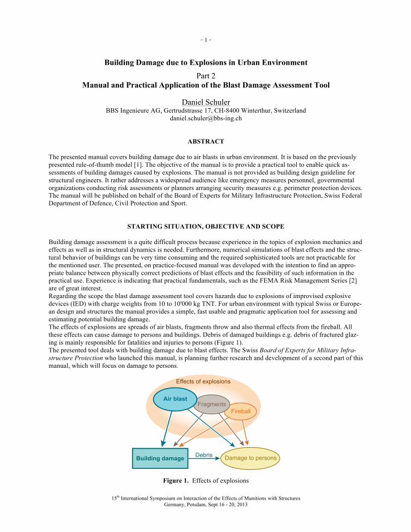
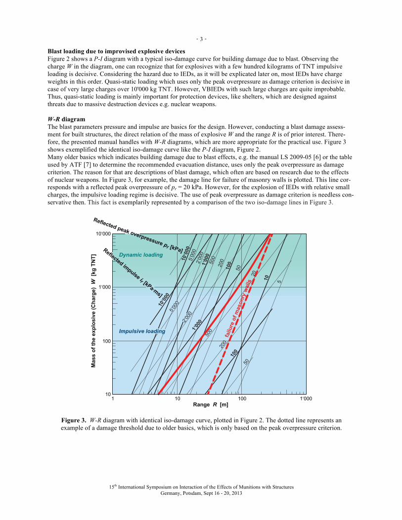
Blast loading due to improvised explosive devices Figure 2 shows a P-I diagram with a typical iso-damage curve for building damage due to blast. Observing the charge W in the diagram, one can recognize that for explosives with a few hundred kilograms of TNT impulsive loading is decisive. Considering the hazard due to IEDs, as it will be explicated later on, most IEDs have charge weights in this order. Quasi-static loading which uses only the peak overpressure as damage criterion is decisive in case of very large charges over 10'000 kg TNT. However, VBIEDs with such large charges are quite improbable. Thus, quasi-static loading is mainly important for protection devices, like shelters, which are designed against threats due to massive destruction devices e.g. nuclear weapons. W-R diagram The blast parameters pressure and impulse are basics for the design. However, conducting a blast damage assess-ment for built structures, the direct relation of the mass of explosive W and the range R is of prior interest. There-fore, the presented manual handles with W-R diagrams, which are more appropriate for the practical use. Figure 3 shows exemplified the identical iso-damage curve like the P-I diagram, Figure 2. Many older basics which indicates building damage due to blast effects, e.g. the manual LS 2009-05 [6] or the table used by ATF [7] to determine the recommended evacuation distance, uses only the peak overpressure as damage criterion. The reason for that are descriptions of blast damage, which often are based on research due to the effects of nuclear weapons. In Figure 3, for example, the damage line for failure of masonry walls is plotted. This line cor-responds with a reflected peak overpressure of pr = 20 kPa. However, for the explosion of IEDs with relative small charges, the impulsive loading regime is decisive. The use of peak overpressure as damage criterion is needless con-servative then. This fact is exemplarily represented by a comparison of the two iso-damage lines in Figure 3.
510
20
5010020
0500
1‘00
0
2‘00
0
5‘00
0
10‘0
00
50
5‘000
200
5001‘0
00
100
2‘000
10‘00
0
Reflected peak overpressure pr [kPa] Reflected impulse ir [kPa .ms]
1‘00010010110
100
1‘000
10‘000
Range R [m]
Mas
s of
the
expl
osiv
e (C
harg
e) W
[kg
TN
T] Dynamic loading
Impulsive loading
failu
re o
f mas
onry
wal
ls
Figure 3. W-R diagram with identical iso-damage curve, plotted in Figure 2. The dotted line represents an example of a damage threshold due to older basics, which is only based on the peak overpressure criterion.
- -
15th International Symposium on Interaction of the Effects of Munitions with Structures Germany, Potsdam, Sept 16 - 20, 2013
4
HAZARD ANALYSIS AND BUILDING DAMAGE ASSESSMENT
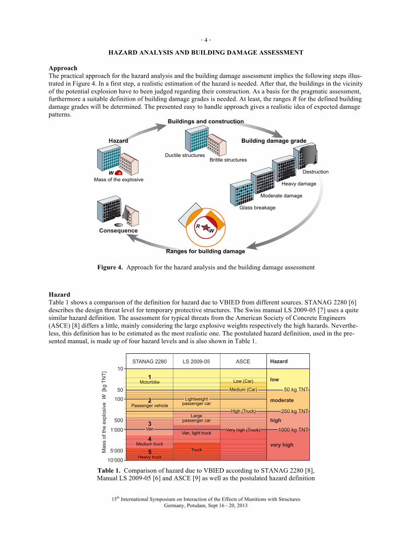
Approach The practical approach for the hazard analysis and the building damage assessment implies the following steps illus-trated in Figure 4. In a first step, a realistic estimation of the hazard is needed. After that, the buildings in the vicinity of the potential explosion have to been judged regarding their construction. As a basis for the pragmatic assessment, furthermore a suitable definition of building damage grades is needed. At least, the ranges R for the defined building damage grades will be determined. The presented easy to handle approach gives a realistic idea of expected damage patterns.
Destruction
Ranges for building damage
WR
Ductile structures
Brittle structures
Buildings and construction
Hazard
Consequence
Mass of the explosive
W
Heavy damage
Moderate damage
Building damage grade
Glass breakage
Figure 4. Approach for the hazard analysis and the building damage assessment
Hazard Table 1 shows a comparison of the definition for hazard due to VBIED from different sources. STANAG 2280 [6] describes the design threat level for temporary protective structures. The Swiss manual LS 2009-05 [7] uses a quite similar hazard definition. The assessment for typical threats from the American Society of Concrete Engineers (ASCE) [8] differs a little, mainly considering the large explosive weights respectively the high hazards. Neverthe-less, this definition has to be estimated as the most realistic one. The postulated hazard definition, used in the pre-sented manual, is made up of four hazard levels and is also shown in Table 1.
10
50
500
5‘000
100
50 kg TNT
250 kg TNT
1000 kg TNT1‘000
10‘000
STANAG 2280 LS 2009-05 ASCE
High (Truck)
Medium (Car)
Low (Car)
Mass o
f th
e e
xplo
siv
e W
[kg T
NT
]
Truck
Van, light truck
Large
passenger car
Lightweight
passenger car
1Motorbike
2Passenger vehicle
4Medium truck
5Heavy truck
3Van Very high (Truck)
low
Hazard
moderate
high
very high
Table 1. Comparison of hazard due to VBIED according to STANAG 2280 [8], Manual LS 2009-05 [6] and ASCE [9] as well as the postulated hazard definition
- -
15th International Symposium on Interaction of the Effects of Munitions with Structures Germany, Potsdam, Sept 16 - 20, 2013
5
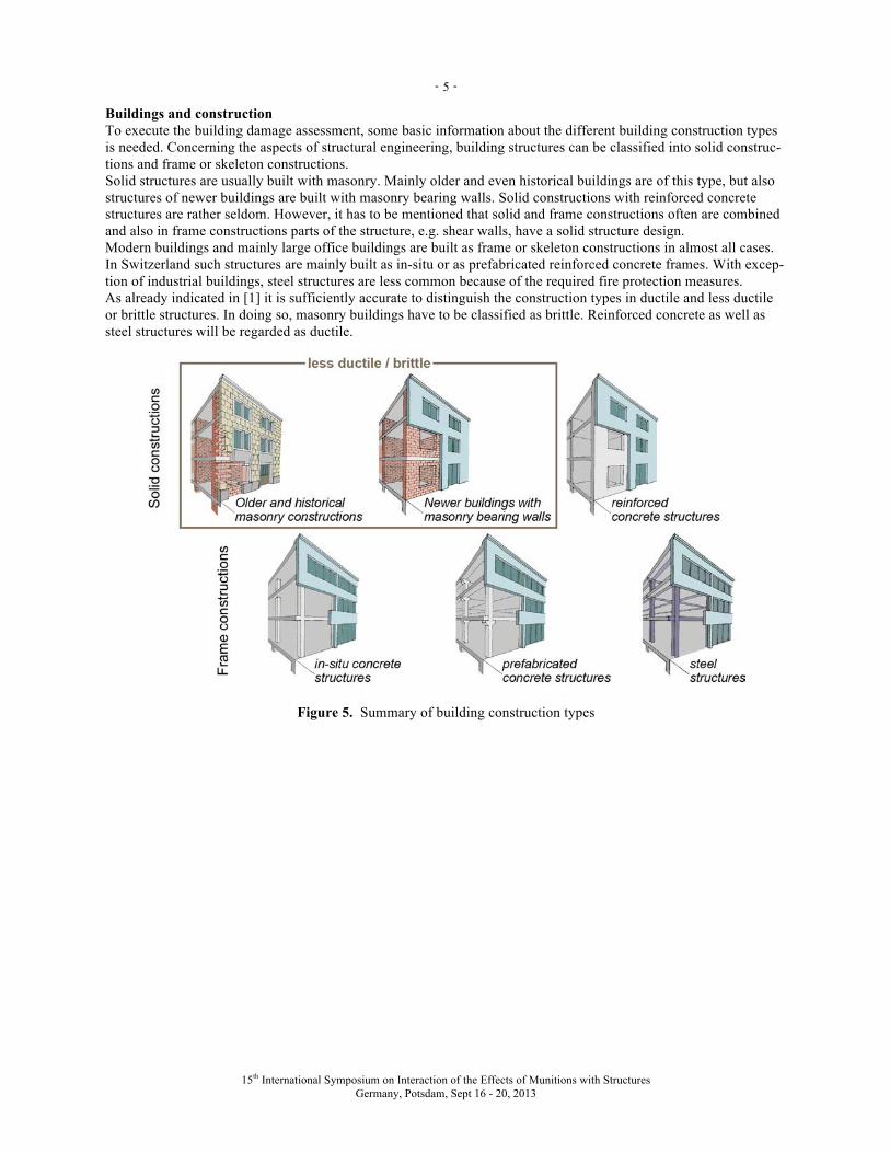
Buildings and construction To execute the building damage assessment, some basic information about the different building construction types is needed. Concerning the aspects of structural engineering, building structures can be classified into solid construc-tions and frame or skeleton constructions. Solid structures are usually built with masonry. Mainly older and even historical buildings are of this type, but also structures of newer buildings are built with masonry bearing walls. Solid constructions with reinforced concrete structures are rather seldom. However, it has to be mentioned that solid and frame constructions often are combined and also in frame constructions parts of the structure, e.g. shear walls, have a solid structure design. Modern buildings and mainly large office buildings are built as frame or skeleton constructions in almost all cases. In Switzerland such structures are mainly built as in-situ or as prefabricated reinforced concrete frames. With excep-tion of industrial buildings, steel structures are less common because of the required fire protection measures. As already indicated in [1] it is sufficiently accurate to distinguish the construction types in ductile and less ductile or brittle structures. In doing so, masonry buildings have to be classified as brittle. Reinforced concrete as well as steel structures will be regarded as ductile.
Figure 5. Summary of building construction types
- -
15th International Symposium on Interaction of the Effects of Munitions with Structures Germany, Potsdam, Sept 16 - 20, 2013
6
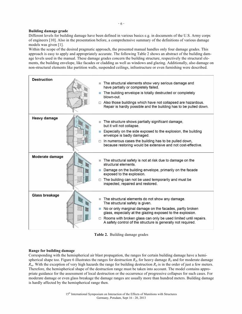
Building damage grade Different levels for building damage have been defined in various basics e.g. in documents of the U.S. Army corps of engineers [10]. Also in the presentation before, a comprehensive summary of the definitions of various damage models was given [1]. Within the scope of the desired pragmatic approach, the presented manual handles only four damage grades. This approach is easy to apply and appropriately accurate. The following Table 2 shows an abstract of the building dam-age levels used in the manual. These damage grades concern the building structure, respectively the structural ele-ments, the building envelope, like facades or cladding as well as windows and glazing. Additionally, also damage on non-structural elements like partition walls, suspended ceilings, infrastructure or even furnishing were described.
Table 2. Building damage grades
Range for building damage Corresponding with the hemispherical air blast propagation, the ranges for certain building damage have a hemi-spherical shape too. Figure 6 illustrates the ranges for destruction Rd, for heavy damage Rh and for moderate damage Rm. With the exception of very high hazards the range for building destruction Rd is in the order of just a few meters. Therefore, the hemispherical shape of the destruction range must be taken into account. The model contains appro-priate guidance for the assessment of local destruction or the occurrence of progressive collapses for such cases. For moderate damage or even glass breakage the damage ranges are usually more than hundred meters. Building damage is hardly affected by the hemispherical range then.
- -
15th International Symposium on Interaction of the Effects of Munitions with Structures Germany, Potsdam, Sept 16 - 20, 2013
7
Figure 6. Ranges for building damage
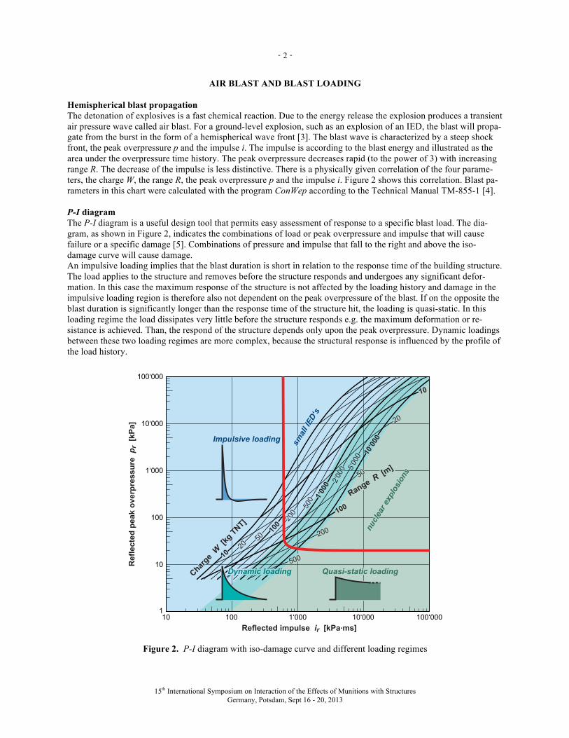
As a function of the mass of explosive W, the ranges R for destruction, heavy damage and moderate damage are plotted in a W-R diagram, shown in Figure 7. It should be noted that for moderate damage a differentiation between ductile and brittle structures is not necessary because such damage mainly concern damage to the building facades. In addition the manual also gives information about the likelihood of glass breakage. The shape and the steepness of this damage thresholds indicate that in this case the peak overpressure of the blast is much more decisive than the impulse (compare also Figure 3).
1‘000100101 5 50 50010
100
1‘000
10‘000
5‘000
500
50
Range R [m]
Mas
s of
the
expl
osiv
e W
[kg
TN
T] Destruction
Ductile Bldg Brittle Bldg
Heavy damage
Ductile Bldg Brittle Bldg
Moderate damage
Ductile/brittle Bldg
Glass breakage
KLJK��§�����ORZ��§����
Probability of fracture
Figure 7. W-R diagram for different damage grades and different building construction types
- -
15th International Symposium on Interaction of the Effects of Munitions with Structures Germany, Potsdam, Sept 16 - 20, 2013
8
PRACTICAL TOOL AND EXAMPLE OF USE
The presented manual provides a clear, easy to handle and useful working tool for a widespread audience like emer-gency measures personnel, governmental organizations conducting risk assessments or planners arranging security measures e.g. perimeter protection devices. By following a few simple steps it is possible to gain a realistic overview of the damage patterns due to explosions in urban environment. Hereafter an example of the practical application of a damage assessment for the downtown area of a Swiss city is illustrated. Step 1: Hazard In the first step a judgment of the expected hazard is required. For a possible terrorist threat with a VBIED in a pas-senger car a hazard level of moderate to high can be estimated. With the help of the following Figure 8 a mass of explosive of 250 kg TNT is assumed.
Figure 8. Practical tool and example of use: Hazard
- -
15th International Symposium on Interaction of the Effects of Munitions with Structures Germany, Potsdam, Sept 16 - 20, 2013
9
Step 2: Buildings and construction To carry on with the second step a judgment of the building construction in the area close to the center of the explo-sion is necessary. Of course it is impossible to conduct an in-depth analysis of the structural design of the affected buildings. However, for an easy distinction in ductile and brittle constructions this is usually not necessary either. The manual delivers illustrative explanation for a quick visual assessment of constructions (Figure 9).
Figure 9. Practical tool and example of use: Buildings and construction
Step 3: Ranges for building damage By proceeding with step 3 the estimation of the range for building destruction, heavy damage and moderate damage is being done. In order to give a clear overview, the application tool provides a comprehensive description of the building damage for every damage grade. The following figures are showing these summaries as well as the W-R diagrams and the map detail with the plotted in damage ranges for the example.
- -
15th International Symposium on Interaction of the Effects of Munitions with Structures Germany, Potsdam, Sept 16 - 20, 2013
10
Figure 10. Practical tool and example of use: Destruction of Buildings
- -
15th International Symposium on Interaction of the Effects of Munitions with Structures Germany, Potsdam, Sept 16 - 20, 2013
11
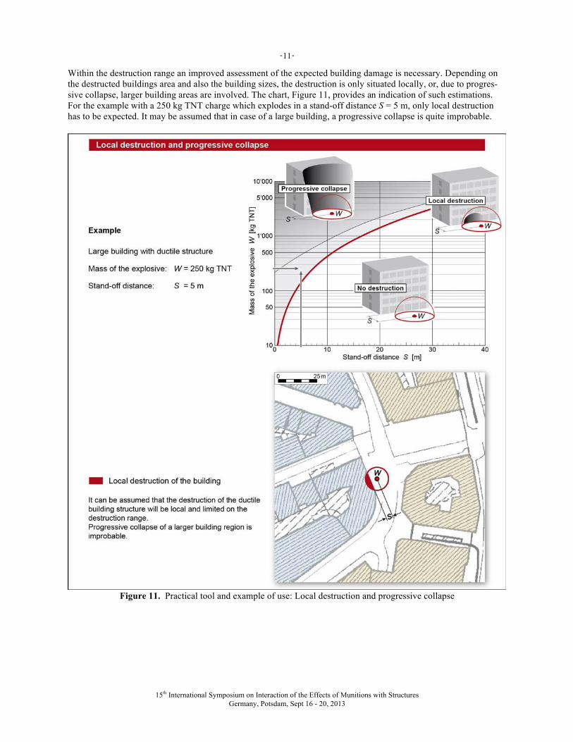
Within the destruction range an improved assessment of the expected building damage is necessary. Depending on the destructed buildings area and also the building sizes, the destruction is only situated locally, or, due to progres-sive collapse, larger building areas are involved. The chart, Figure 11, provides an indication of such estimations. For the example with a 250 kg TNT charge which explodes in a stand-off distance S = 5 m, only local destruction has to be expected. It may be assumed that in case of a large building, a progressive collapse is quite improbable.
Figure 11. Practical tool and example of use: Local destruction and progressive collapse
- -
15th International Symposium on Interaction of the Effects of Munitions with Structures Germany, Potsdam, Sept 16 - 20, 2013
12
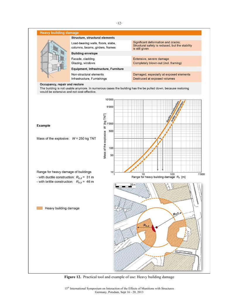
Figure 12. Practical tool and example of use: Heavy building damage
- -
15th International Symposium on Interaction of the Effects of Munitions with Structures Germany, Potsdam, Sept 16 - 20, 2013
13
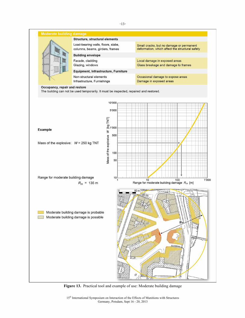
Figure 13. Practical tool and example of use: Moderate building damage
- -
15th International Symposium on Interaction of the Effects of Munitions with Structures Germany, Potsdam, Sept 16 - 20, 2013
14
Nomenclature i impulse p peak overpressure R range S stand-off distance W mass of the explosive (TNT equivalent), charge Subscripts d destruction d,b destruction of brittle structures d,d destruction of ductile structures h heavy damage h,b heavy damage of brittle structures h,d heavy damage of ductile structures m moderate damage r reflected air blast
SUMMARY
Building damage ranges due to blast effects are generally known. Often they are based on the explosion of very large charge weights e.g. nuclear explosions, thus peak overpressure of the blast is an appropriate damage criterion. In case of threats by improvised explosive devices (IED), equivalent TNT explosive weights of a few 100 kg are frequently decisive. The use of peak overpressures as damage criteria is needless conservative then because build-ings, respectively their structural elements, are exposed to impulsive loadings. Since damage criteria based on P-I diagrams are less transparent, the manual specifies damage ranges for building destruction, heavy and moderate building damage as well as for glazing breakage as charge-distance relationships in W-R diagrams.
ACKNOWLEDGEMENT
The research and the preparation of the manual were conducted as part of the activities of the Board of Experts for Military Infrastructure Protection SIM of armasuisse Real Estate, Swiss Federal Department of Defence, Civil Pro-tection and Sport.
REFERENCES
1. Kummer, P.O., Building Damages due to Explosions in Urban Environments - Part 1: Development of a Blast Damage Assessment Tool, 15th ISIEMS (International Symposium on the Interaction of Effects of Munitions with Structures), Potsdam, Germany, September 2013
2. FEMA, Reference Manual to Mitigate Potential Terrorist Attacks Against Buildings, Report 426, Federal Emer-gency Management Agency, Washington, December 2003
3. Cormie, D., Mays, G., Smith, P. (Eds.), Blast effects on buildings, Second edition, Thomas Telford 2009 4. U.S. Departments of the Army, Fundamentals of Protective Design for Conventional Weapons, Technical Manu-
al TM-855-1, November 1986 5. Krauthammer, T., Modern Protective Structures, CRC Press, Taylor & Francis Group LLC, Boca Raton FL 2008 6. Schuler, D., Mitigation of Terrorist Attacks with Vehicle Borne Improvised Explosive Devices - Manual, Report
LS 2009-05, SPIEZ LABORATORY, Spiez, Switzerland, February 2009 7. ATF, US Department of Justice, Bureau of Alcohol, Tobacco, Firearms and Explosives, Washington DC 8. NATO, Standardization Agreement STANAG 2280, Edition 1, Design Threat Levels and Handover Procedures
for Temporary Protective Structures, 2008 9. ASCE, Design for Physical Security: State of the Practice Report, American Society of Civil Engineers, Reston,
VA, 1997 10. U.S. Army Corps of Engineers, Protective Design Center Technical Report PDC TR-06-01 Rev 1, Methodology
Manual for the Single-Degree-of-Freedom Blast Effects Design Spreadsheets (SBEDS), September 2008