Embed Size (px)
Citation preview
Building Materials and Construction 15CV36
Department of Civil Engineering, ATMECE Page 1
MODULE 3 – LINTELS, BALCONY AND ARCHES
Structure
3.1.1 Introduction to Lintels
3.1.2 Objectives
3.1.3 Classification
3.1.4 Method of construction
3.1.5 Questions
3.1.6 Outcome
3.1.7 Future study
3.2.1 Introduction to Chejja
3.2.2 Objective
3.2.3 Function
3.2.4 Method of construction
3.2.5 Types of Chejja
3.2.6 Questions
3.2.7 Outcome
3.2.8 Future study
3.3.1 Introduction to Canopy or Portico & Balcony
3.3.2 Objectives
3.3.3 Functions
3.3.4 Method of construction
3.3.5 Outcome
3.3.6 Questions
3.3.7 Future Study
3.4.1 Introduction to Masonry Arches
3.4.2 Objectives
3.4.3 Technical terms
3.4.4 Types of arches
3.4.5 Stability of an arch
3.4.6 Questions
3.4.7 Outcome
3.4.8 Future study
Building Materials and Construction 15CV36
Department of Civil Engineering, ATMECE Page 2
Lintels
3.1.1 Introduction
A lintel is a horizontal member which is placed across an opening to support the position of the
structure above it. A lintel is thus a sort of beam in which width will be equal to the width of the
wall, and the ends of which are built into the wall. In general, it should be seen that the bearing of the
Lintel i.e., the distance up to which it is inserted in the supporting wall, should be the minimum on
the following three considerations:
1.100mm or
2. Height of lintel or
3. 1/10thor 1/12thof the span of lintel
3.1.2 Objectives
To study the terms used in lintels
To study the types of lintels
To gain the knowledge on uses of lintels
3.1.3 Classification of Lintels
Lintels are classified into the following types according to the materials of construction:
1. Timber lintels 2. Stone lintels 3. Brick lintels
4. Steel lintels 5. Reinforced concrete lintels
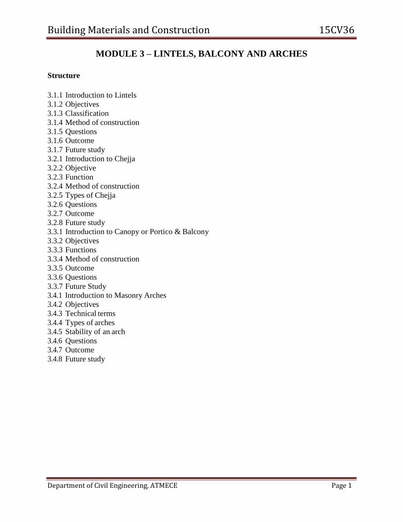
1. Wood or Timber lintels:
These lintels consist of pieces of timber which are placed across the opening.
These are used in hilly areas or in places where timber is easily available.
These are structurally weak and vulnerable to fire.
They are also liable to decay more comparative to other types.
A bearing of about 15cm to 20cm should be provided and a minimum thickness of about 80mm should be provided in case of wooden lintel.
Building Materials and Construction 15CV36
Department of Civil Engineering, ATMECE Page 3
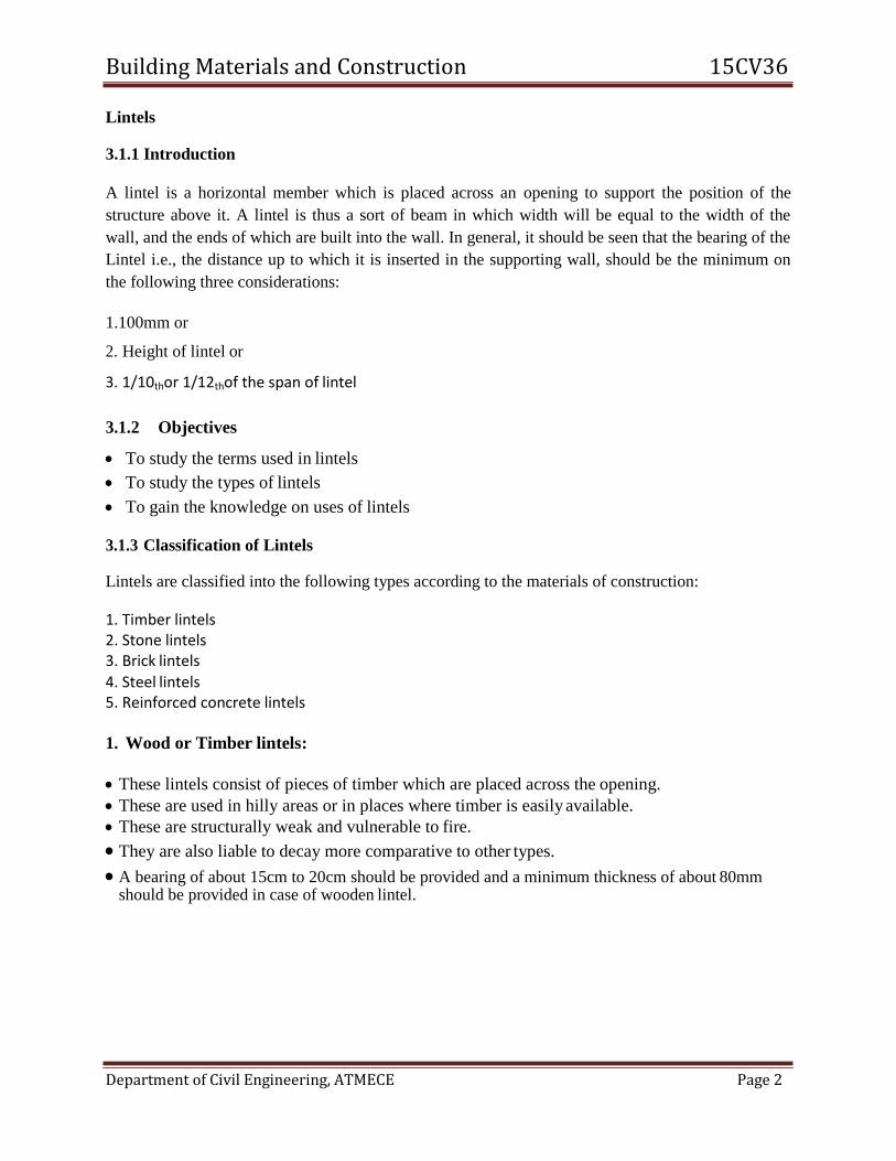
2. Stone Lintels
The thickness of stone lintel is kept equal to 10cm per meter of span with a minimum of 15cm.
They are not generally used because
The stone possesses low tensile resistance
It cracks of subjected to vibratory loads
It is difficult to obtain a good stone of required depth and it proves to be costly at places where the
stone is not available.
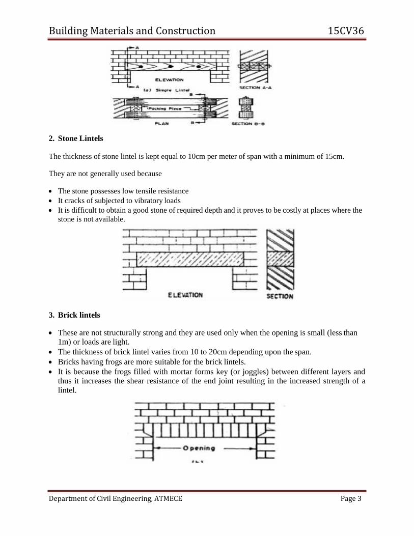
3. Brick lintels
These are not structurally strong and they are used only when the opening is small (less than 1m) or loads are light.
The thickness of brick lintel varies from 10 to 20cm depending upon the span.
Bricks having frogs are more suitable for the brick lintels.
It is because the frogs filled with mortar forms key (or joggles) between different layers and thus it increases the shear resistance of the end joint resulting in the increased strength of a
lintel.

Building Materials and Construction 15CV36
Department of Civil Engineering, ATMECE Page 4
4. Steel lintels
These are provided where the opening is large and where the super-imposed loads are also
heavy.
These lintels consist of steel angles or rolled steel joints. The steel angles are used for small spans and light loading and rolled steel joints is used for large spans and heavy loading.
A steel lintel is preferred when there is no space available to accommodate the rise of an arch.
5. Reinforced Cement Concrete Lintel
At present, the lintels of R.C.C are widely used to span the openings for doors, windows, etc.
in a structure because of their strength, rigidity, fire resistance, economy and ease in construction.
R.C.C lintels are suitable for all the loads and for any span.
The width of lintel is equal to width of wall.
Depth of lintel is dependent of length of span and magnitude of loading.
Main reinforcement is provided at the bottom and half of these bars are cranked at the ends.
Stirrups are provided to resist transverse shear
The usual concrete mix for R.C.C.lintel is 1:2:4 (cement: sand: agg)
Reinforcement for lintels for ordinary loading
The number of main bars for a lintel depends upon the load from wall to be carried above and the
span of the opening. The diameter of tar varies with the span.
Upto 1.2m span – 10mm dia
1.2 to .2 span – 12mm dia
2 to 3m span – 16mm dia are used
3.1.4 Method of construction
Construct the brick wall up to the lintel bottom level.
Construct the centering work. It may be wood and mud centering or steel centering.

Building Materials and Construction 15CV36
Department of Civil Engineering, ATMECE Page 5
Depending upon the types of lintel, construct the lintel. Ex. If R.C.C. lintel, place the
reinforcement cage on centering platform.
Fix the side shuttering; Place the sheath covering all round the reinforcement cage.
Pour the concrete. After 24 hours remove the shutters and cure it for about 28 days.
3.1.5 Questions
1. What is a lintel
2. What are types of lintels?
3. Explain the method of construction of lintels.
3.1.6 Outcome
Able to study the lintels
Able to know the types of lintels
Able to know the method of construction of lintels
3.1.7 Future study
https://www.slideshare.net/SARASWATIPATHARIYA/lintels-and-arches-in-construction.
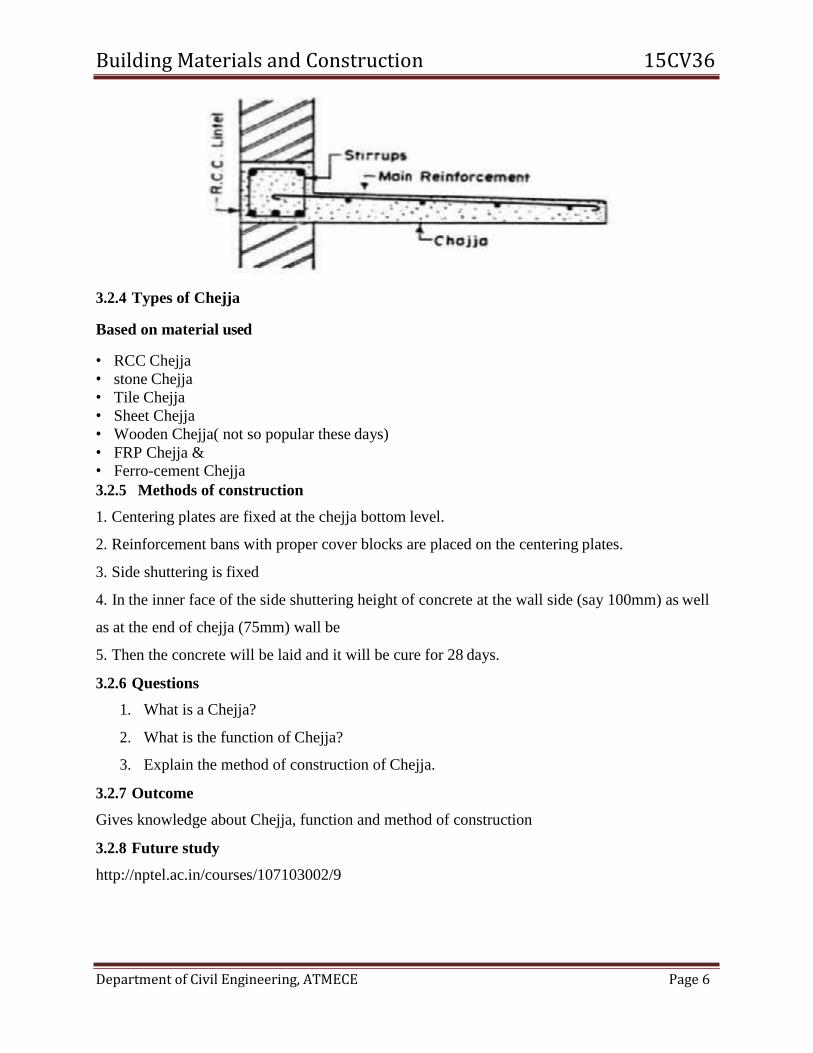
3.2.1 Chejja:
It is an extended position and thin slab above doors, windows and ventilators.
3.2.2 Objectives
To know about Chejja and its functions
3.2.3 Function
The Chejja gives protection to the opening space against rain water and direct sunlight. It is also
called as weather shed.
Building Materials and Construction 15CV36
Department of Civil Engineering, ATMECE Page 6
3.2.4 Types of Chejja
Based on material used
• RCC Chejja
• stone Chejja
• Tile Chejja
• Sheet Chejja
• Wooden Chejja( not so popular these days)
• FRP Chejja &
• Ferro-cement Chejja
3.2.5 Methods of construction
1. Centering plates are fixed at the chejja bottom level.
2. Reinforcement bans with proper cover blocks are placed on the centering plates.
3. Side shuttering is fixed
4. In the inner face of the side shuttering height of concrete at the wall side (say 100mm) as well
as at the end of chejja (75mm) wall be
5. Then the concrete will be laid and it will be cure for 28 days.
3.2.6 Questions
1. What is a Chejja?
2. What is the function of Chejja?
3. Explain the method of construction of Chejja.
3.2.7 Outcome
Gives knowledge about Chejja, function and method of construction
3.2.8 Future study
http://nptel.ac.in/courses/107103002/9
Building Materials and Construction 15CV36
Department of Civil Engineering, ATMECE Page 7
Canopy or Portico
3.3.1 Introduction
A canopy is an overhead roof or else a structure over which a fabric or metal covering is
attached, able to provide shade or shelter from weather conditions such as sun, hail, snow and
rain. A canopy can also be a tent, generally without a floor.
Balcony
A Balcony is a platform which is projected from wall of a building, constructed above ground
floor, supported by columns or consoled brackets and enclosed within balustrade.
3.3.2 Objectives
To Know about Canopy, Balcony and its functions
3.3.3 Function of Canopy
Generally it is used for parking vehicles.
Function of Balcony
It is used for relaxation purpose.
It gives a good architectural appearance to a structure.
3.3.4 Method of construction
1. Construct the walls up to roof level.
2. Centering is placed in front of that wall (outside the building) where portico or balcony is
necessary. 3. The centering is supported by vertical members called jacks or wooden poles.
4. These poles are in turn rests on the hard ground it is for portico or it should rest on
1st floor slab if the balcony is in 2nd floor.
5. Reinforcement bars are placed on these centering sheets and are properly tied using binding
wires.
6. Finally concrete is laid to the sufficient thickness and properly cured for desiredperiod.
3.3.5 Questions
1. Briefly explain the terms used in arches?
2. Explain the types of arches lintels?
3. Explain the types of balcony?
Building Materials and Construction 15CV36
Department of Civil Engineering, ATMECE Page 8
3.3.6 Outcomes
Able to study the arches and lintels work
Able to distinguish arches and lintels work
Able to know the types of balcony, arches and lintels
3.3.7 Future study
http://nptel.ac.in/courses/105105109/pdf/m5l33.pdf
Arches
3.4.1 Introduction
An arch is a structure which is constructed to span across an opening. It generally consists of
small wedge-shaped units which are joined together with mortar.
3.4.2 Objectives
To study the terms used in arches
To study the types of arches
To gain the knowledge on uses of arches
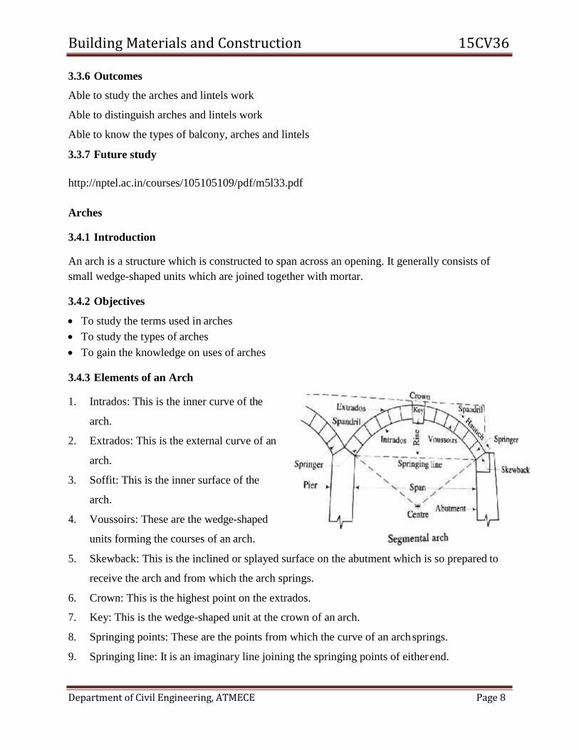
3.4.3 Elements of an Arch
1. Intrados: This is the inner curve of the
arch.
2. Extrados: This is the external curve of an
arch.
3. Soffit: This is the inner surface of the
arch.
4. Voussoirs: These are the wedge-shaped
units forming the courses of an arch.
5. Skewback: This is the inclined or splayed surface on the abutment which is so prepared to
receive the arch and from which the arch springs.
6. Crown: This is the highest point on the extrados.
7. Key: This is the wedge-shaped unit at the crown of an arch.
8. Springing points: These are the points from which the curve of an arch springs.
9. Springing line: It is an imaginary line joining the springing points of either end.
Building Materials and Construction 15CV36
Department of Civil Engineering, ATMECE Page 9
10. Abutment: This is the end support of an arch.
11. Piers: These are the intermediate supports of an arcade.
12. Span: This is the clear horizontal distance between the supports.
13. Rise: This is the clear vertical distance between the highest point on the intrados and the
springing line.
14. Centre: This is the geometrical center of the curve of an arch.
3.4.4 Types of arches
The various types of arches can be classified as follows
1. According to shape
2. According to number of centers
3. According to workmanship
4. According to materials of construction
Classification of arches according to shapes
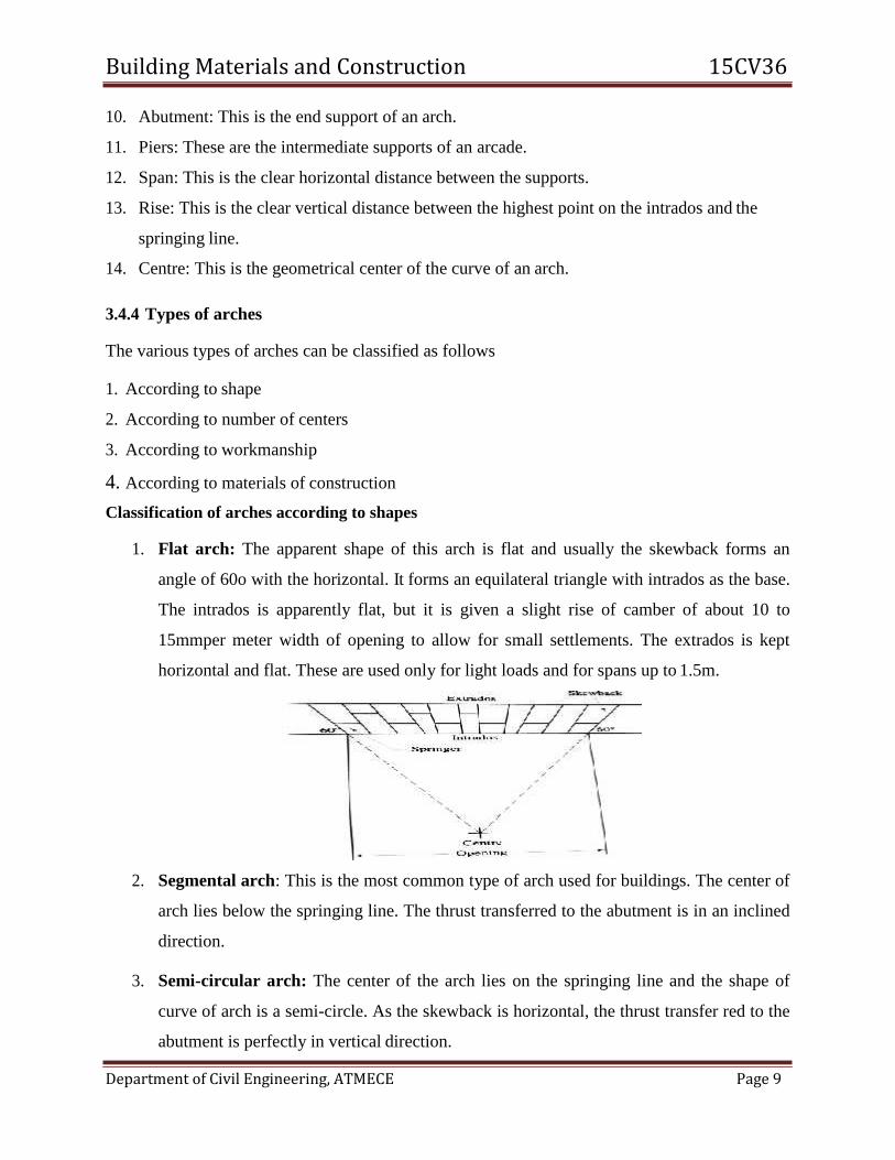
1. Flat arch: The apparent shape of this arch is flat and usually the skewback forms an
angle of 60o with the horizontal. It forms an equilateral triangle with intrados as the base.
The intrados is apparently flat, but it is given a slight rise of camber of about 10 to
15mmper meter width of opening to allow for small settlements. The extrados is kept
horizontal and flat. These are used only for light loads and for spans up to 1.5m.
2. Segmental arch: This is the most common type of arch used for buildings. The center of
arch lies below the springing line. The thrust transferred to the abutment is in an inclined
direction.
3. Semi-circular arch: The center of the arch lies on the springing line and the shape of
curve of arch is a semi-circle. As the skewback is horizontal, the thrust transfer red to the
abutment is perfectly in vertical direction.
Building Materials and Construction 15CV36
Department of Civil Engineering, ATMECE Page 10
4. Semi-elliptical arch: The shape of the arch in semi-elliptical and it has more than one
centre
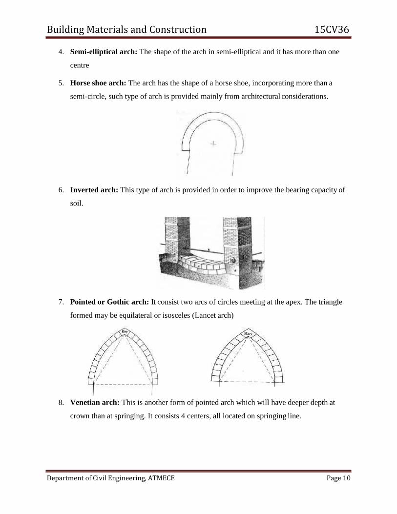
5. Horse shoe arch: The arch has the shape of a horse shoe, incorporating more than a
semi-circle, such type of arch is provided mainly from architectural considerations.
6. Inverted arch: This type of arch is provided in order to improve the bearing capacity of
soil.
7. Pointed or Gothic arch: It consist two arcs of circles meeting at the apex. The triangle
formed may be equilateral or isosceles (Lancet arch)
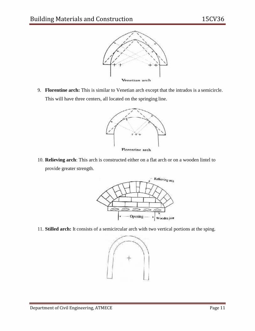
8. Venetian arch: This is another form of pointed arch which will have deeper depth at
crown than at springing. It consists 4 centers, all located on springing line.
Building Materials and Construction 15CV36
Department of Civil Engineering, ATMECE Page 11
9. Florentine arch: This is similar to Venetian arch except that the intrados is a semicircle.
This will have three centers, all located on the springing line.
10. Relieving arch: This arch is constructed either on a flat arch or on a wooden lintel to
provide greater strength.
11. Stilled arch: It consists of a semicircular arch with two vertical portions at the sping.
Building Materials and Construction 15CV36
Department of Civil Engineering, ATMECE Page 12
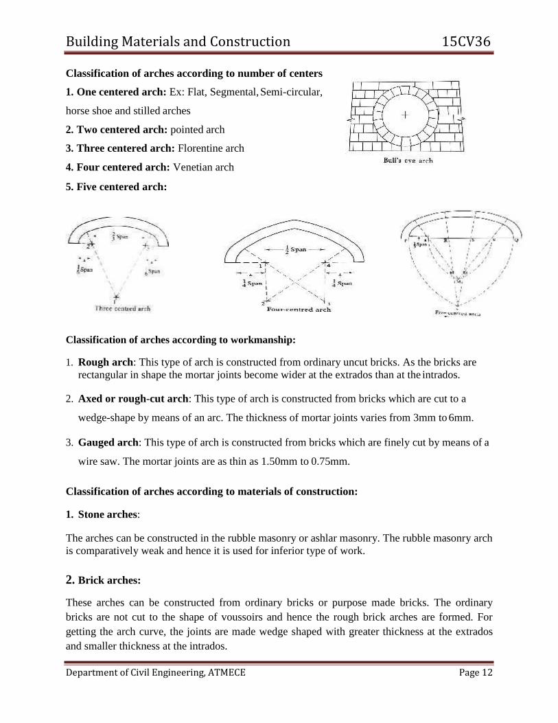
Classification of arches according to number of centers
1. One centered arch: Ex: Flat, Segmental, Semi-circular,
horse shoe and stilled arches
2. Two centered arch: pointed arch
3. Three centered arch: Florentine arch
4. Four centered arch: Venetian arch
5. Five centered arch:
Classification of arches according to workmanship:
1. Rough arch: This type of arch is constructed from ordinary uncut bricks. As the bricks are
rectangular in shape the mortar joints become wider at the extrados than at the intrados.
2. Axed or rough-cut arch: This type of arch is constructed from bricks which are cut to a
wedge-shape by means of an arc. The thickness of mortar joints varies from 3mm to 6mm.
3. Gauged arch: This type of arch is constructed from bricks which are finely cut by means of a
wire saw. The mortar joints are as thin as 1.50mm to 0.75mm.
Classification of arches according to materials of construction:
1. Stone arches:
The arches can be constructed in the rubble masonry or ashlar masonry. The rubble masonry arch
is comparatively weak and hence it is used for inferior type of work.
2. Brick arches:
These arches can be constructed from ordinary bricks or purpose made bricks. The ordinary
bricks are not cut to the shape of voussoirs and hence the rough brick arches are formed. For
getting the arch curve, the joints are made wedge shaped with greater thickness at the extrados
and smaller thickness at the intrados.

Building Materials and Construction 15CV36
Department of Civil Engineering, ATMECE Page 13
3. Concrete arches:
These arches can be constructed of the precast cement concrete blocks or monolithic concrete.
The blocks are similar to stones and are prepared by casting cement concrete in specially
prepared moulds. The monolithic concrete arches are constructed from cast in-situ concrete and
suitable for big spans.
3.4.5 Stability of an arch
An arch transmits the superimposed load to the abutments or piers or side walls through the
combined action of friction between the surfaces of voussoirs and the cohesion of mortar.
Following are the four ways of failure o an arch:
1. Crushing of the masonry
2. Rotation of some joint about an edge
3. Sliding of voussoir.
4. Uneven settlement of abutment or pier.
1. Crushing of the masonry:
In this case, the compressive stress or thrust exceeds the safe crushing strength of the materials and the arch fails due to crushing of the masonry.
The measures to avoid failure of arch due to this reason are as follows:
The material used for construction should be of adequate strength.
The size of voussoirs should be properly designed to bear the thrust transmitted throughthem.
If necessary the voussoirs of variable heights may be provided i,e less height near crown and max
height at skewback.
2. Rotation of some joint about an edge:
To prevent the rotation of joint, the line of resistance should be kept within intrados and
extrados. The line of thrust should also be made to cross the joint away from the edge so as to
prevent the crushing of that edge. It should fall within the middle third portion of the archheight.
3. Sliding of voussoir:
To safeguard against the sliding of adjacent voussoirs due to transverse shear, the voussoir of
greater height should be provided.
4. Uneven settlement of abutment or pier:
The secondary stresses in the arch are developed due to the uneven settlement of the supports of arch and to avoid such conditions, the following precautions should be taken
Building Materials and Construction 15CV36
Department of Civil Engineering, ATMECE Page 14
The arch should be symmetrical so that unequal settlements of the two abutments or abutment
and pier are minimized.
The supports of arch should be strong enough to take or resist the thrust as well as to bear all
the loads transferred to them through the arc.
3.4.6 Questions
1. What is an arch?
2. What are the types of arches?
3. Write a note on stability of an arch.
3.4.7 Outcome
Able to study the arches
Able to distinguish arches
Able to know the types of arches.
3.4.8 Future study
http://nptel.ac.in/courses/105105109/32
Building Materials and Construction 15CV36
Department of Civil Engineering, ATMECE Page 15
ROOFS AND FLOORS
Structure
3.5.1 Introduction
3.5.2 Objective
3.5.3 Classification of Roofs
3.5.4 Sloped Roof or Pitched roof
3.5.5 Flat Roof
3.5.6 Wooden truss
3.5.7 Steel truss
3.5.8 Roof Coverings
3.5.9 Flooring
3.5.10 Selection of Flooring Material
3.5.11 Types of Flooring
3.5.12 Outcomes
3.5.13 Questions
3.5.14 Future Study

Building Materials and Construction 15CV36
Department of Civil Engineering, ATMECE Page 16
Roofs
3.5.1 Introduction
A roof is defined as the upper most part of a building, provided as a structural covering, to protect the
building from weather. The structural elements may be trusses, portals, beams, slabs, shells or domes
and the roof coverings may be A.C. sheets, G.I. sheets, wooden shingles, tiles, slates etc.
3.5.2 Objectives
To study the terms used in roofs and floors
To study the types of roofs and floors
To gain the knowledge on wide uses of types of roofs and floors based on economy as well
as the requirement
Requirements of good roof
• It should be durable against adverse effects
• It should withstand the load
• It should be a perfect insulator
• It should be well-drained
• It should have better water-proofing arrangement
3.5.3 Classification of Roofs
1. Flat roofs or terraced roofs
2. Pitched or sloping roofs
3. Curved roofs
3.5.4 Sloped Roof or Pitched roof
A roof with sloping surface is known as a pitched or sloped roof. These roofs suitable for
buildings in coastal regions or in areas where in rainfall are very heavy.
Buildings with limited width and simple shape can generally be covered satisfactorily by
pitched roofs.
The slope varies according to span, climatic condition, and nature of covering materials.
Building Materials and Construction 15CV36
Department of Civil Engineering, ATMECE Page 17
Elements of a Pitched roof
Types of pitched roofs
1. Single roofs
Single roofs consist of only common rafters which are secured at the ridge (to ridge beam) and
wall plate. These are used when span is less so that no intermediate support is required for the
rafters.
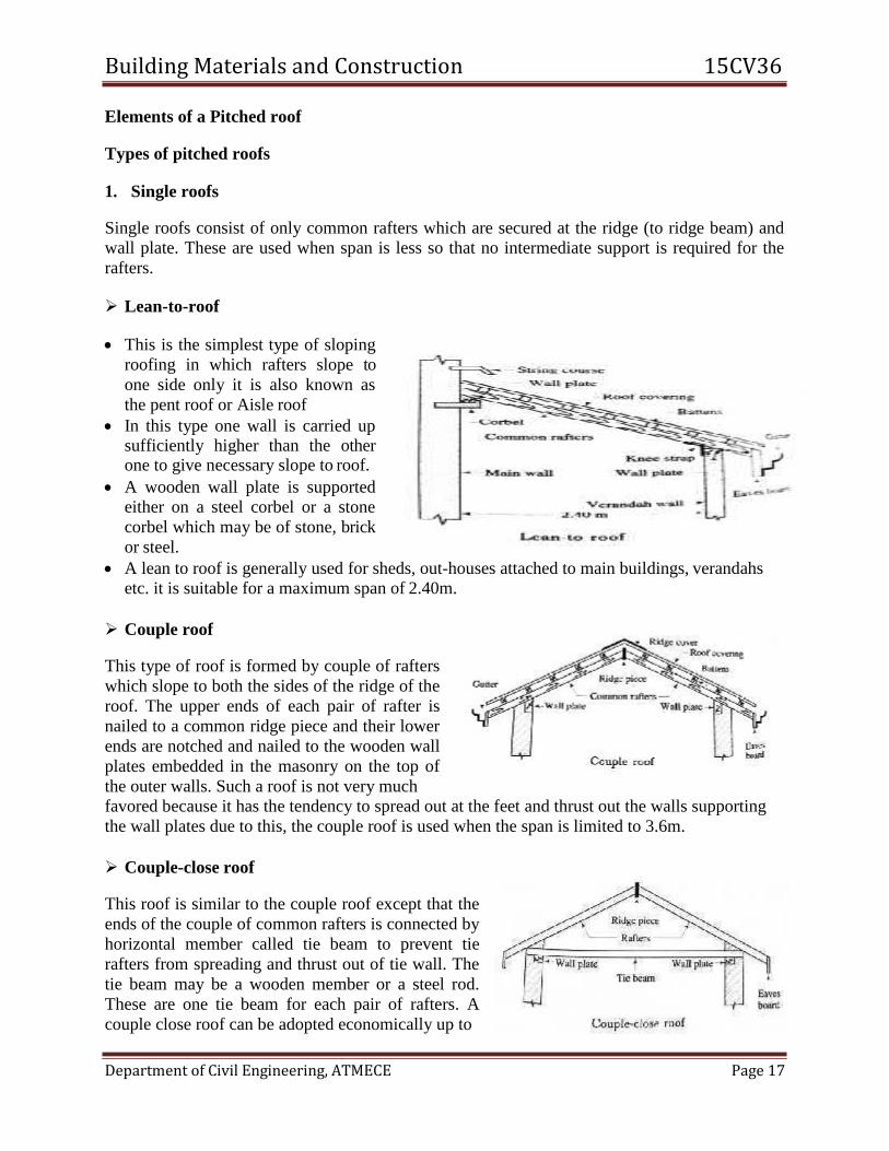
Lean-to-roof
This is the simplest type of sloping
roofing in which rafters slope to
one side only it is also known as
the pent roof or Aisle roof
In this type one wall is carried up sufficiently higher than the other one to give necessary slope to roof.
A wooden wall plate is supported
either on a steel corbel or a stone
corbel which may be of stone, brick
or steel.
A lean to roof is generally used for sheds, out-houses attached to main buildings, verandahs
etc. it is suitable for a maximum span of 2.40m.
Couple roof
This type of roof is formed by couple of rafters
which slope to both the sides of the ridge of the
roof. The upper ends of each pair of rafter is
nailed to a common ridge piece and their lower
ends are notched and nailed to the wooden wall
plates embedded in the masonry on the top of
the outer walls. Such a roof is not very much
favored because it has the tendency to spread out at the feet and thrust out the walls supporting
the wall plates due to this, the couple roof is used when the span is limited to 3.6m.
Couple-close roof
This roof is similar to the couple roof except that the
ends of the couple of common rafters is connected by
horizontal member called tie beam to prevent tie
rafters from spreading and thrust out of tie wall. The
tie beam may be a wooden member or a steel rod.
These are one tie beam for each pair of rafters. A
couple close roof can be adopted economically up to
Building Materials and Construction 15CV36
Department of Civil Engineering, ATMECE Page 18
a span of 4.2 m.
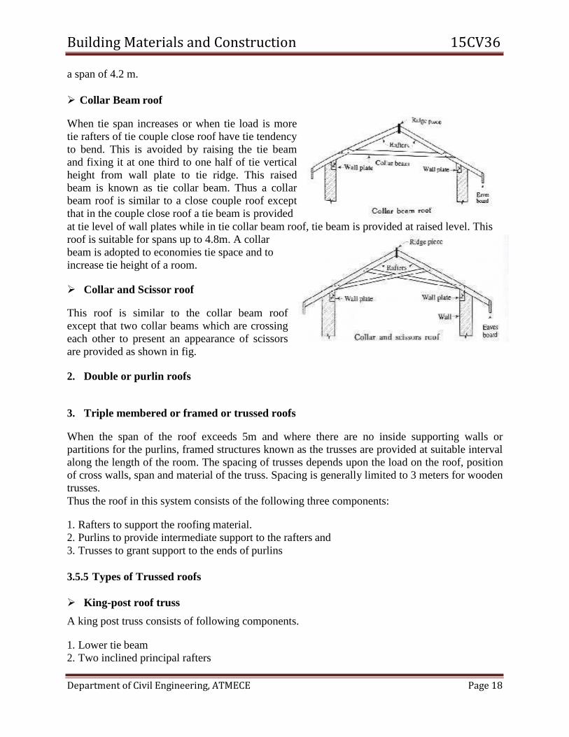
Collar Beam roof
When tie span increases or when tie load is more
tie rafters of tie couple close roof have tie tendency
to bend. This is avoided by raising the tie beam
and fixing it at one third to one half of tie vertical
height from wall plate to tie ridge. This raised
beam is known as tie collar beam. Thus a collar
beam roof is similar to a close couple roof except
that in the couple close roof a tie beam is provided
at tie level of wall plates while in tie collar beam roof, tie beam is provided at raised level. This
roof is suitable for spans up to 4.8m. A collar
beam is adopted to economies tie space and to
increase tie height of a room.
Collar and Scissor roof
This roof is similar to the collar beam roof
except that two collar beams which are crossing
each other to present an appearance of scissors
are provided as shown in fig.
2. Double or purlin roofs
3. Triple membered or framed or trussed roofs
When the span of the roof exceeds 5m and where there are no inside supporting walls or
partitions for the purlins, framed structures known as the trusses are provided at suitable interval
along the length of the room. The spacing of trusses depends upon the load on the roof, position
of cross walls, span and material of the truss. Spacing is generally limited to 3 meters for wooden
trusses.
Thus the roof in this system consists of the following three components:
1. Rafters to support the roofing material.
2. Purlins to provide intermediate support to the rafters and
3. Trusses to grant support to the ends of purlins
3.5.5 Types of Trussed roofs
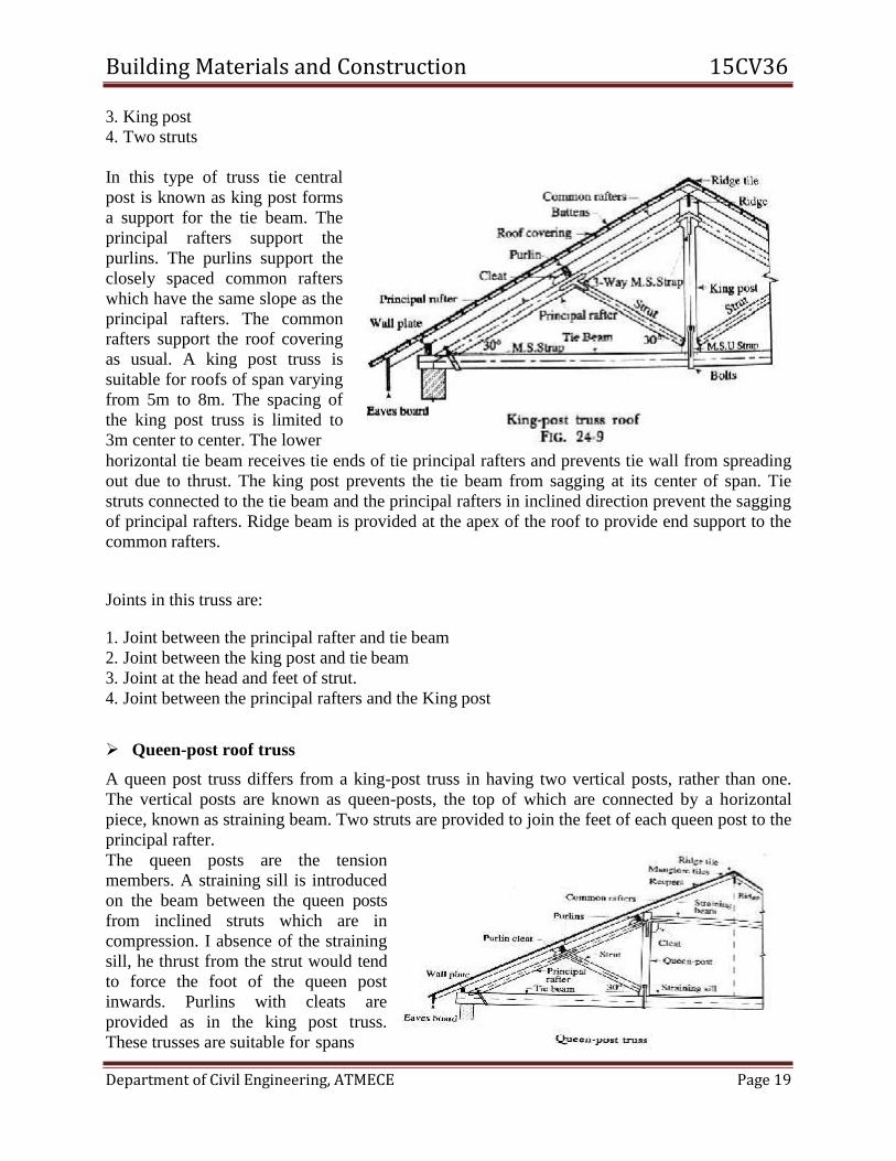
King-post roof truss
A king post truss consists of following components.
1. Lower tie beam
2. Two inclined principal rafters
Building Materials and Construction 15CV36
Department of Civil Engineering, ATMECE Page 19
3. King post
4. Two struts
In this type of truss tie central
post is known as king post forms
a support for the tie beam. The
principal rafters support the
purlins. The purlins support the
closely spaced common rafters
which have the same slope as the
principal rafters. The common
rafters support the roof covering
as usual. A king post truss is
suitable for roofs of span varying
from 5m to 8m. The spacing of
the king post truss is limited to
3m center to center. The lower
horizontal tie beam receives tie ends of tie principal rafters and prevents tie wall from spreading
out due to thrust. The king post prevents the tie beam from sagging at its center of span. Tie
struts connected to the tie beam and the principal rafters in inclined direction prevent the sagging
of principal rafters. Ridge beam is provided at the apex of the roof to provide end support to the
common rafters.
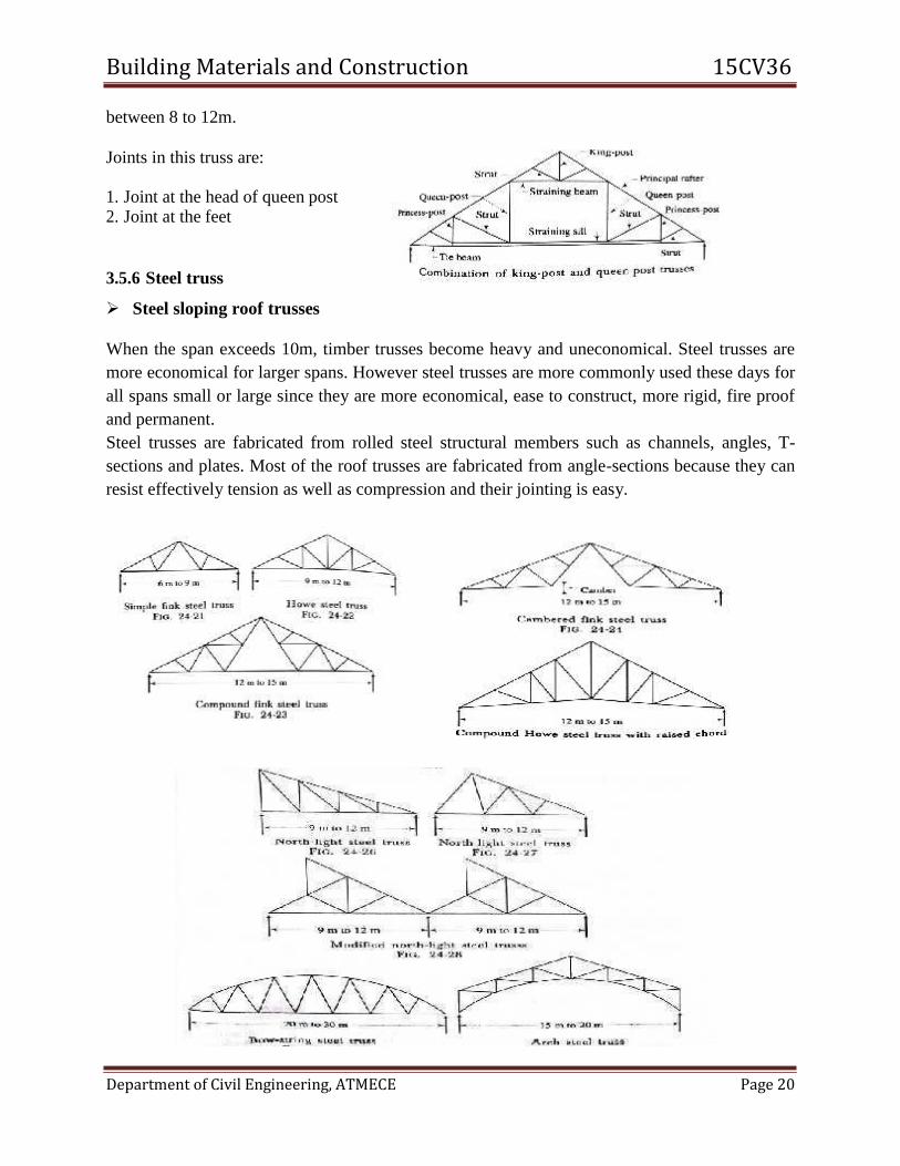
Joints in this truss are:
1. Joint between the principal rafter and tie beam
2. Joint between the king post and tie beam
3. Joint at the head and feet of strut.
4. Joint between the principal rafters and the King post
Queen-post roof truss
A queen post truss differs from a king-post truss in having two vertical posts, rather than one.
The vertical posts are known as queen-posts, the top of which are connected by a horizontal
piece, known as straining beam. Two struts are provided to join the feet of each queen post to the
principal rafter.
The queen posts are the tension
members. A straining sill is introduced
on the beam between the queen posts
from inclined struts which are in
compression. I absence of the straining
sill, he thrust from the strut would tend
to force the foot of the queen post
inwards. Purlins with cleats are
provided as in the king post truss.
These trusses are suitable for spans
Building Materials and Construction 15CV36
Department of Civil Engineering, ATMECE Page 20
between 8 to 12m.
Joints in this truss are:
1. Joint at the head of queen post 2. Joint at the feet
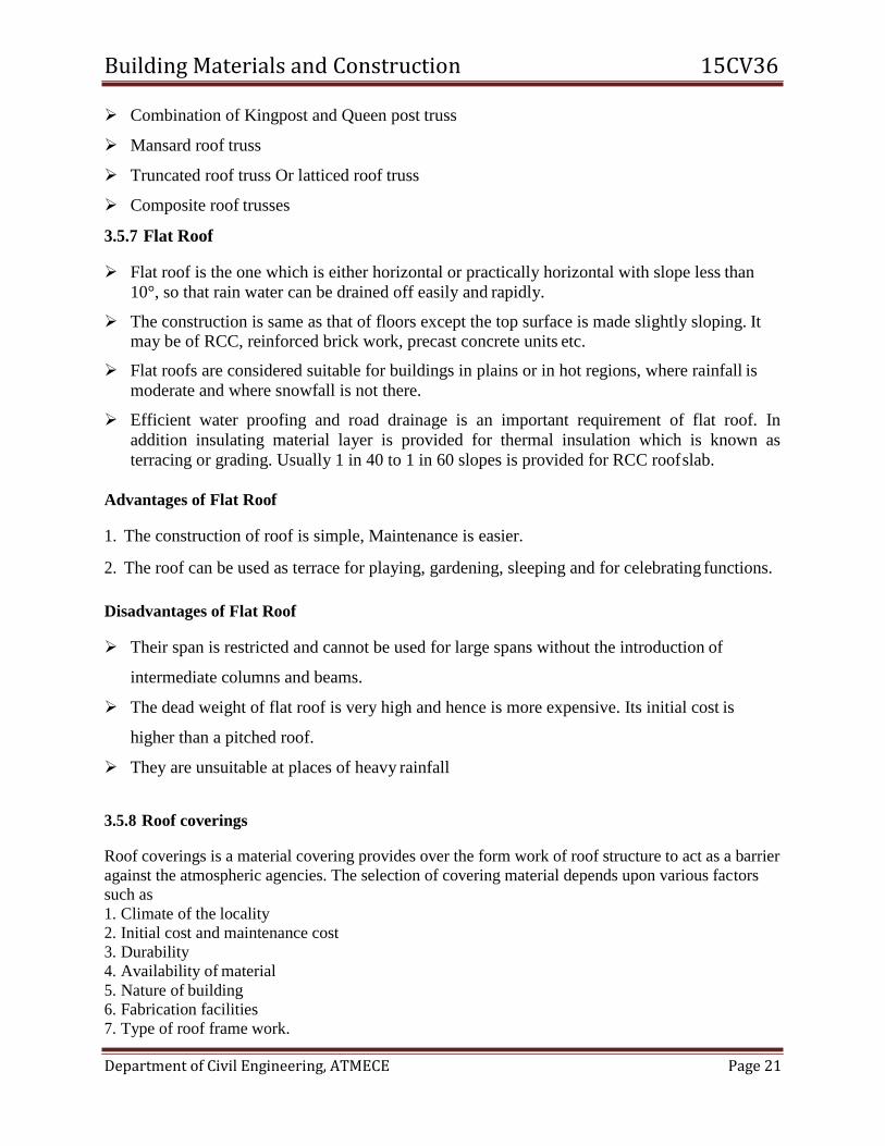
3.5.6 Steel truss
Steel sloping roof trusses
When the span exceeds 10m, timber trusses become heavy and uneconomical. Steel trusses are
more economical for larger spans. However steel trusses are more commonly used these days for
all spans small or large since they are more economical, ease to construct, more rigid, fire proof
and permanent.
Steel trusses are fabricated from rolled steel structural members such as channels, angles, T-
sections and plates. Most of the roof trusses are fabricated from angle-sections because they can
resist effectively tension as well as compression and their jointing is easy.
Building Materials and Construction 15CV36
Department of Civil Engineering, ATMECE Page 21
Combination of Kingpost and Queen post truss
Mansard roof truss
Truncated roof truss Or latticed roof truss
Composite roof trusses
3.5.7 Flat Roof
Flat roof is the one which is either horizontal or practically horizontal with slope less than
10°, so that rain water can be drained off easily and rapidly.
The construction is same as that of floors except the top surface is made slightly sloping. It may be of RCC, reinforced brick work, precast concrete units etc.
Flat roofs are considered suitable for buildings in plains or in hot regions, where rainfall is
moderate and where snowfall is not there.
Efficient water proofing and road drainage is an important requirement of flat roof. In
addition insulating material layer is provided for thermal insulation which is known as
terracing or grading. Usually 1 in 40 to 1 in 60 slopes is provided for RCC roof slab.
Advantages of Flat Roof
1. The construction of roof is simple, Maintenance is easier.
2. The roof can be used as terrace for playing, gardening, sleeping and for celebrating functions.
Disadvantages of Flat Roof
Their span is restricted and cannot be used for large spans without the introduction of
intermediate columns and beams.
The dead weight of flat roof is very high and hence is more expensive. Its initial cost is
higher than a pitched roof.
They are unsuitable at places of heavy rainfall
3.5.8 Roof coverings
Roof coverings is a material covering provides over the form work of roof structure to act as a barrier
against the atmospheric agencies. The selection of covering material depends upon various factors
such as
1. Climate of the locality
2. Initial cost and maintenance cost
3. Durability
4. Availability of material
5. Nature of building
6. Fabrication facilities
7. Type of roof frame work.
Building Materials and Construction 15CV36
Department of Civil Engineering, ATMECE Page 22
8. Special features of the locality
Thatch Roofs
• Light roof covering
• Combustible
• Absorbs moisture
• Liable to decay
• Unstable for high winds
• Used in rural areas because it is cheaper to construct
Ordinary Half–round Country tiles
• Used for low cost houses
• Liable to breakage
• Frequent maintenance
Shingles
• Used adopted in hilly areas
Patent tile roofs
• Mangalore tiles are one of such patent tiles.
Trafford asbestos-cement tiles
• Made up of cement and asbestos material.
• They posses less corrugations
Eternit slates
• They have good Fire resisting property
• They are light in weight and provide cool environment.
• Less affected by weather
Corrugated Galvanized Iron sheets
• Prepared by pressing wrought iron sheets by rollers with grooves or teeth.
• They are coated with zinc.
• They are costly and do not offer resistance to fire and sound.
Asbestos-cement corrugated sheets
Building Materials and Construction 15CV36
Department of Civil Engineering, ATMECE Page 23
• The cement is mixed with 15% of asbestos fibers and paste so formed is pressed under
rollers with groove or teeth.
• They are cheap, Light in weight, Fire resisting
• Strong, tough, sound-proof, impervious and durable
RCC Roof
Elements of RCC slab are
Cement
Coarse Aggregate
Fine aggregate
Mild Steel Bars
Binding Wires
Water
Shuttering materials such as wooden planks, iron sheets.
3.5.9 Flooring
The solid construction between the plinth level and roof level are known as floors and the
exposed top surfaces of floors are termed as floorings.
Components of a floor:
A floor is composed of two components:
i. Sub-floor, base course or floor base
ii. Floor covering or simply, flooring.
3.5.10 Selection of Flooring Material
Following factors are to be carefully considered before selecting the material for flooring of a
particular building
1. Appearance
2. Cleanliness
3. Cost
4. Damp resistance
5. Durability
6. Fire resistance
7. Hardness
8. Maintenance
9. Thermal Insulation
10. Slipperiness
Building Materials and Construction 15CV36
Department of Civil Engineering, ATMECE Page 24
Appearance: covering should give pleasing appearance; it should produce a desired color effect and architectural beauty. Floorings of terrazzo, mosaic, tiles and marble give good
appearance.
Cleanliness: The flooring should be capable of being cleaned easily, and it should be non- absorbent. It should have effective resistance against absorption of oil, grease etc.
Cost: the cost of the material should be in conformity with the type of building, and its likely use. Floor coverings of marble etc are very costly and may be used only for residential
buildings.
Damp resistance: Flooring should offer sufficient resistance against dampness, so that
healthy environment is obtained in the building. Flooring of concrete, terrazzo, mosaic etc are
preferred for this purpose, while flooring of wood, rubber etc are preferred for this purpose,
while flooring o wood, rubber, etc are not suitable for damp conditions.
Durability: The flooring should have sufficient resistance to wear, temperature changes,
disintegration with time and decay so that long life is obtained. From this point of view, flooring of marble, terrazzo, concrete etc are considered to be of best type.
Fire resistance: This is more important for upper floors. Flooring material should offer sufficient fire resistance so that fire barriers are obtained between different levels of a
building.
Hardness: It should be hard so as to have resistance to indentation marks, imprints etc likely to be caused by shifting of furniture, equipment etc.
Maintenance: the flooring material should require leapt maintenance. However, whenever
repairs are required, it should be such that repairs can be done easily with least possible expenditure.
Thermal insulation: the flooring should offer reasonably good thermal insulation so that
comfort is imparted to the residents of the building.
Slipperiness: The surface of floor should be smooth but at the same time, it should not be too
slippery.
3.5.11 Types of flooring
In order to give a pleasuring appearance to the upper surface of the floor, the various materials
are placed on it. It is used to provide for ground floor. The materials used for floor finish or floor
covering or flooring are:
1. Granolithic finish
2. Mosaic
3. Ceramic
4. Marble
5. Polished Granite
6. Industrial flooring
7. Wood or timber
8. Asphalt
Building Materials and Construction 15CV36
Department of Civil Engineering, ATMECE Page 25
9. Glass
10. Linoleum flooring
11. Cork
12. Rubber etc.
1. Granolithic finish:
In industrial building, hard wearing surface is sometimes required. This can be achieved by
applying granolithic finish over the concrete topping. The topping consists of 1:2:4 cement
concrete, laid to the desired thickness in one single operation in the panel. Alternate panels are
laid first prior to laying the concrete in the panel a coat of neat cement slurry is applied This
cement slurry laid on rough finished base course ensures proper bond of topping with the base
course. Granolithic finish consists of rich concrete made with very hard and tough quality coarse
aggregate graded from 13mm IS sieve. The concrete mix proportion varies from 1:1:2 to 1:1:3
for heavy duty floors to 1:2:3 for public buildings. The thickness of finish may be minimum
25mm when laid monolithically with the top concrete and 35mm when laid over hardened
surface. However for public buildings such as schools hospitals etc. the thickness of the finish
may be 13mm to 20mm.
2. Mosaic Flooring:
Mosaic flooring is made of small pieces of broken tiles of china glazed or of cement or of marble
arranged in different pattern. These pieces are cut to desired shapes and sizes. A concrete base is
prepared as in the case of concrete flooring. The base course of concrete flooring may be 7.5 to
10cm thick, either in lean cement concrete or lime concrete containing 40% mortar of 1:2 lime
sand and 60% coarse aggregate of 40mm nominal size. The base course is laid over well
compacted soil, compacted properly and leveled to rough surface. It is properly cured and over it
5 to 8cm thick lime surkhi mortar is spread and leveled over an area which can be completed
conveniently within working period so that the mortar may not get dried before the floor is
finished. On this a 3mm thick cementing material , in the form of a paste of two parts of slaked
lime
3.5.12 Questions
1. Briefly explain the terms used in roofs and floors?
2. Explain the types of roofs and floors?
3. Explain the uses of roofs and floors?
Building Materials and Construction 15CV36
Department of Civil Engineering, ATMECE Page 26
3.5.13 Outcomes
Able to study the roofs work
Able to distinguish different types of roofs
Will be knowing the types of and uses of floors
3.5.14 Future Study
https://www.vssut.ac.in/lecture_notes/lecture1424085991.pdf1