Embed Size (px)
Citation preview
Building Tomorrow’s NetworksSession #1: New High-Speed and Long Reach Optical
Interfaces
January 20, 2018
2
Introductions
• Panel Organizers– John D’Ambrosia (Futurewei), Acting Chair, IEEE 802.3 Beyond 10km Optical PHYs Study Group– Peter Stassar (Huawei), ITU-T Q6/15 Rapporteur– Pete Anslow (Ciena), ITU-T Q6/15 Associate Rapporteur
• Moderator: Pete Anslow• Panelists
– David Law – Chair, IEEE 802.3 Ethernet Working Group– Steve Trowbridge – Chairman, ITU-T Study Group 15– Jeffery Maki, Juniper Networks– Gary Nicholl, Cisco– Bernd Teichmann, Nokia
• Panel Goals– Clarify the characteristics of the network topologies that each respective group is seeking to
define optical solutions to address.– Leverage knowledge between the two groups in understanding the technical challenges of the
different network topologies.
3
Agenda
• Introductions –– IEEE 802.3 Beyond 10km Optical PHYs Study Group
– IEEE 802.3 – David Law
– ITU-T – Steve Trowbridge
• Presentations– Bernd Teichmann – ITU-T G.698.2
– Gary Nicholl - MSO Application
– Jeffery Maki – Industry Perspective – Standards (including OIF 400ZR) / Industry MSAs
• Discussion

4
IntroductionIEEE 802.3 Beyond 10km Optical PHYs Study Group
Current Status of Study Group • Scope - Beyond 10km Optical PHYs for 50 Gb/s, 100 Gb/s, 200
Gb/s, and 400 Gb/s Ethernet
• 50 GbE for at least 40 km Adopted Reach Objective:

5
IntroductionIEEE 802.3 Beyond 10km Optical PHYs Study Group
Source – Beyond 10km July 2018 CFI -http://www.ieee802.org/3/cfi/0717_1/CFI_01_0717.pdf
Defining scope of IEEE 802.3 efforts in relation to ITU-T has been key
• “Beyond 10km” Study Group objectives proposal targeting MSOs included “appropriate support for DWDM systems”
• What does this mean to Beyond 10km Study Group , IEEE 802.3, and ITU-T?
• Simple diagram and common industry terminology causing confusion
IEEE 802.3 Ethernet
David LawChair, IEEE 802.3 Ethernet Working Group
7
IEEE 802.3 Ethernet WG Activities
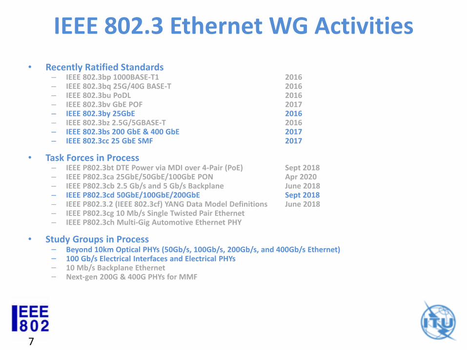
• Recently Ratified Standards– IEEE 802.3bp 1000BASE-T1 2016– IEEE 802.3bq 25G/40G BASE-T 2016– IEEE 802.3bu PoDL 2016– IEEE 802.3bv GbE POF 2017– IEEE 802.3by 25GbE 2016– IEEE 802.3bz 2.5G/5GBASE-T 2016– IEEE 802.3bs 200 GbE & 400 GbE 2017– IEEE 802.3cc 25 GbE SMF 2017
• Task Forces in Process– IEEE P802.3bt DTE Power via MDI over 4-Pair (PoE) Sept 2018– IEEE P802.3ca 25GbE/50GbE/100GbE PON Apr 2020– IEEE P802.3cb 2.5 Gb/s and 5 Gb/s Backplane June 2018– IEEE P802.3cd 50GbE/100GbE/200GbE Sept 2018– IEEE P802.3.2 (IEEE 802.3cf) YANG Data Model Definitions June 2018– IEEE P802.3cg 10 Mb/s Single Twisted Pair Ethernet – IEEE P802.3ch Multi-Gig Automotive Ethernet PHY
• Study Groups in Process– Beyond 10km Optical PHYs (50Gb/s, 100Gb/s, 200Gb/s, and 400Gb/s Ethernet)– 100 Gb/s Electrical Interfaces and Electrical PHYs– 10 Mb/s Backplane Ethernet– Next-gen 200G & 400G PHYs for MMF
8
IEEE 802.3 / ITU-T Cooperation
• IEEE P802.3ae 10 Gb/s
– LAN PHY
– WAN PHY
• IEEE P802.3ba onward
– “Provide appropriate support for OTN”
ITU-T Study Group 15Optical Interface Specificationsand relationship to IEEE 802.3
Steve TrowbridgeChairman, ITU-T Study Group 15
10
Historical Distinction:“Client” vs. “Line” Interfaces
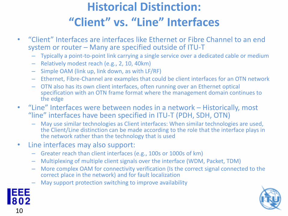
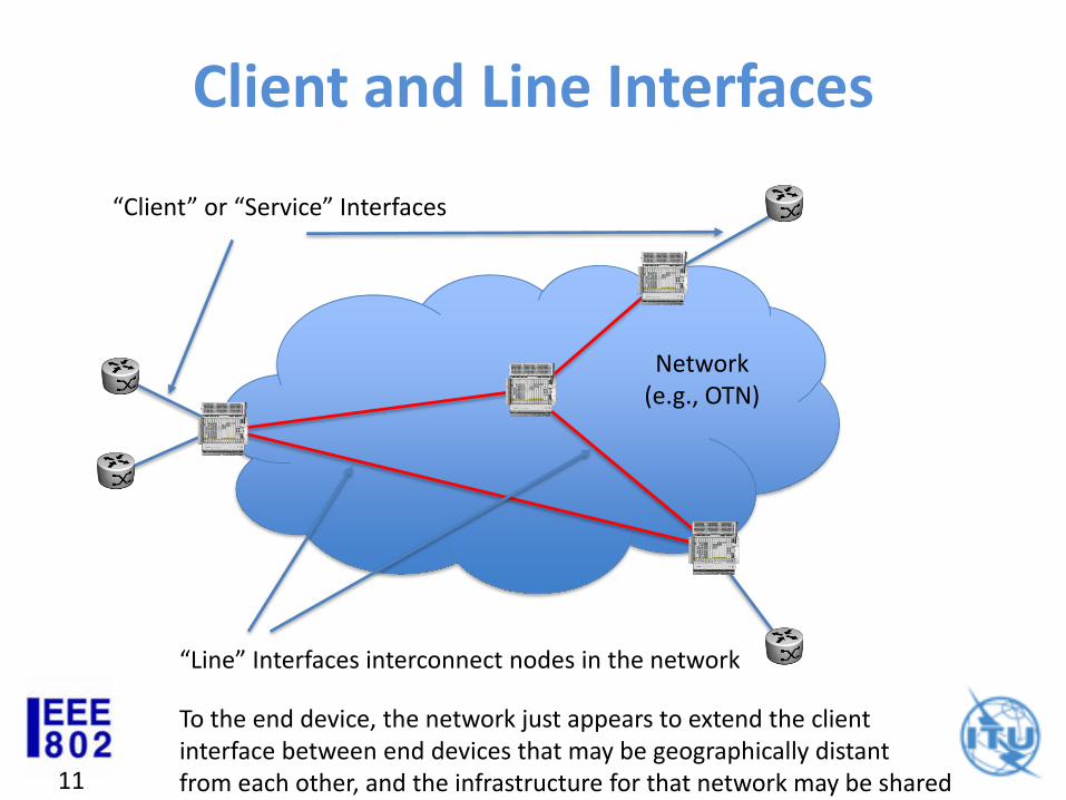
• “Client” Interfaces are interfaces like Ethernet or Fibre Channel to an end system or router – Many are specified outside of ITU-T
– Typically a point-to-point link carrying a single service over a dedicated cable or medium– Relatively modest reach (e.g., 2, 10, 40km)– Simple OAM (link up, link down, as with LF/RF)– Ethernet, Fibre-Channel are examples that could be client interfaces for an OTN network– OTN also has its own client interfaces, often running over an Ethernet optical
specification with an OTN frame format where the management domain continues to the edge
• “Line” Interfaces were between nodes in a network – Historically, most “line” interfaces have been specified in ITU-T (PDH, SDH, OTN)
– May use similar technologies as Client interfaces: When similar technologies are used, the Client/Line distinction can be made according to the role that the interface plays in the network rather than the technology that is used
• Line interfaces may also support:– Greater reach than client interfaces (e.g., 100s or 1000s of km)– Multiplexing of multiple client signals over the interface (WDM, Packet, TDM)– More complex OAM for connectivity verification (Is the correct signal connected to the
correct place in the network) and for fault localization– May support protection switching to improve availability
11
Client and Line Interfaces
Network(e.g., OTN)
“Client” or “Service” Interfaces
“Line” Interfaces interconnect nodes in the network
To the end device, the network just appears to extend the clientinterface between end devices that may be geographically distantfrom each other, and the infrastructure for that network may be shared
12
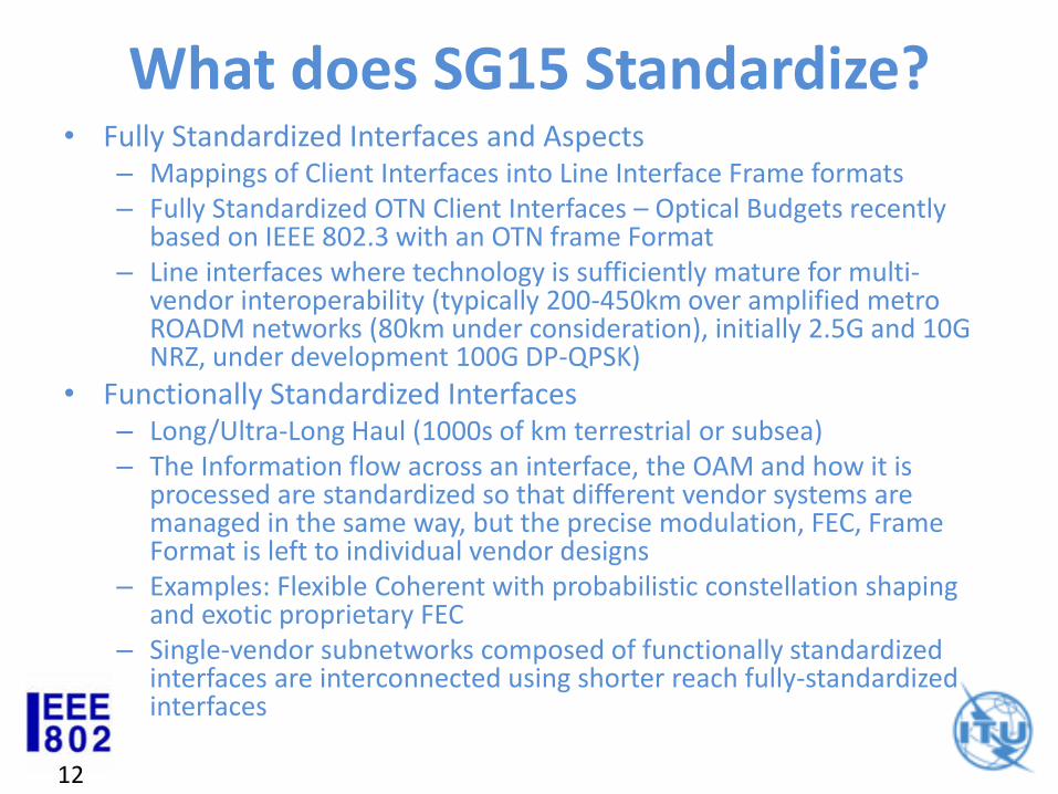
What does SG15 Standardize?• Fully Standardized Interfaces and Aspects
– Mappings of Client Interfaces into Line Interface Frame formats– Fully Standardized OTN Client Interfaces – Optical Budgets recently
based on IEEE 802.3 with an OTN frame Format– Line interfaces where technology is sufficiently mature for multi-
vendor interoperability (typically 200-450km over amplified metro ROADM networks (80km under consideration), initially 2.5G and 10G NRZ, under development 100G DP-QPSK)
• Functionally Standardized Interfaces– Long/Ultra-Long Haul (1000s of km terrestrial or subsea)– The Information flow across an interface, the OAM and how it is
processed are standardized so that different vendor systems are managed in the same way, but the precise modulation, FEC, Frame Format is left to individual vendor designs
– Examples: Flexible Coherent with probabilistic constellation shaping and exotic proprietary FEC
– Single-vendor subnetworks composed of functionally standardized interfaces are interconnected using shorter reach fully-standardized interfaces
13
OTN Client Interfaces based on Ethernet Optics (Link Types 1 & 3)
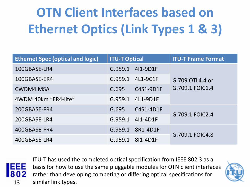
Ethernet Spec (optical and logic) ITU-T Optical ITU-T Frame Format
100GBASE-LR4 G.959.1 4I1-9D1F
G.709 OTL4.4 orG.709.1 FOIC1.4
100GBASE-ER4 G.959.1 4L1-9C1F
CWDM4 MSA G.695 C4S1-9D1F
4WDM 40km “ER4-lite” G.959.1 4L1-9D1F
200GBASE-FR4 G.695 C4S1-4D1FG.709.1 FOIC2.4
200GBASE-LR4 G.959.1 4I1-4D1F
400GBASE-FR4 G.959.1 8R1-4D1FG.709.1 FOIC4.8
400GBASE-LR4 G.959.1 8I1-4D1F
ITU-T has used the completed optical specification from IEEE 802.3 as a basis for how to use the same pluggable modules for OTN client interfaces rather than developing competing or differing optical specifications for similar link types.
14
Ethernet “Line” Interfaces• Proposals to define Ethernet over link types 4-6 appear
to be proposals to define an Ethernet “Line” interface as opposed to the traditional Ethernet “Client” interface
• All existing standards for optical link types 4-6 have been developed by Q6/15 (ITU-T G.698.1 (unamplified); G.698.2 (amplified)
• IEEE 802.3 and ITU-T SG15 should avoid developing (competing) optical specifications for these link types for similar signaling rates and channel characteristics that have differences that preclude using the same components for both IEEE 802.3 and ITU-T applications
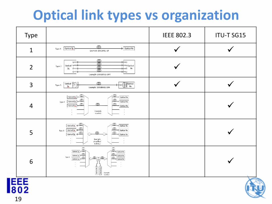
Optical link types
To attempt to avoid differences in terminology between organizations (and individuals) getting in the way of clear communication, six optical link types that have been the subject of standardization by the two groups are illustrated and given a “type number” in the following slides
Pete Anslow
IEEE 802.3 Secretary SG15 Q6 Associate Rapporteur
IEEE 802.3 – ITU-T SG15 Liaison
16
OpticalTx
OpticalRx
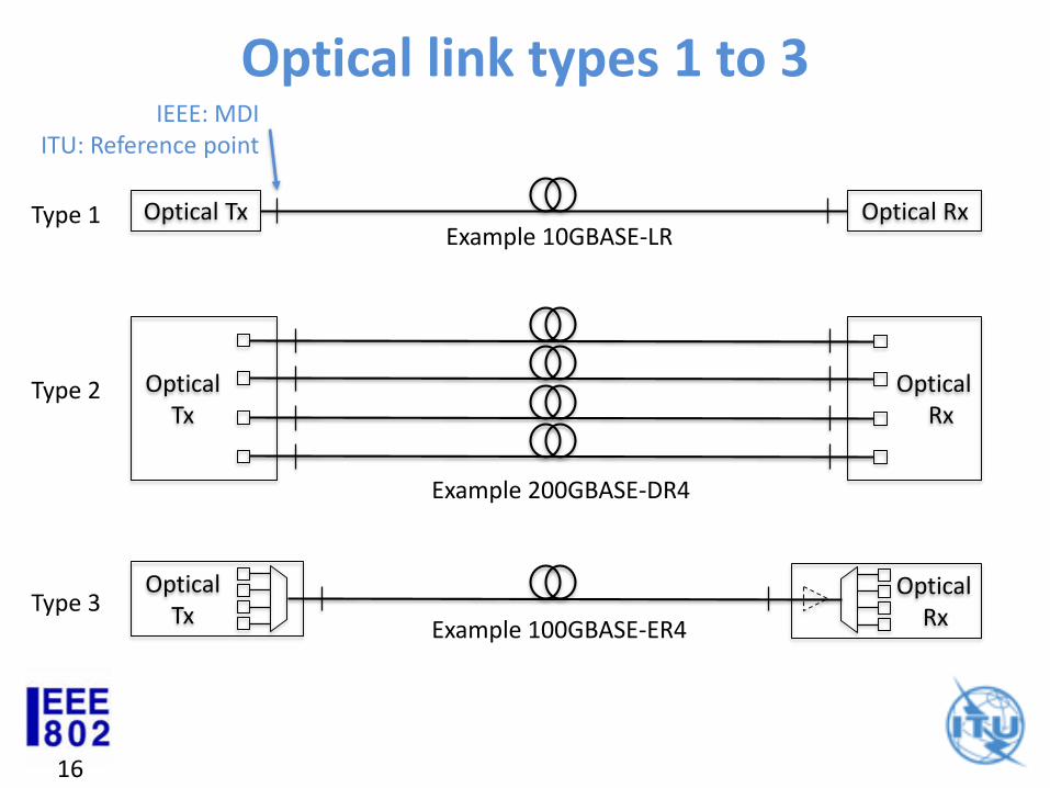
Type 3
Optical Tx Optical RxType 1
Example 100GBASE-ER4
Example 10GBASE-LR
Optical link types 1 to 3
OpticalTx
OpticalRx
Type 2
Example 200GBASE-DR4
IEEE: MDIITU: Reference point
17
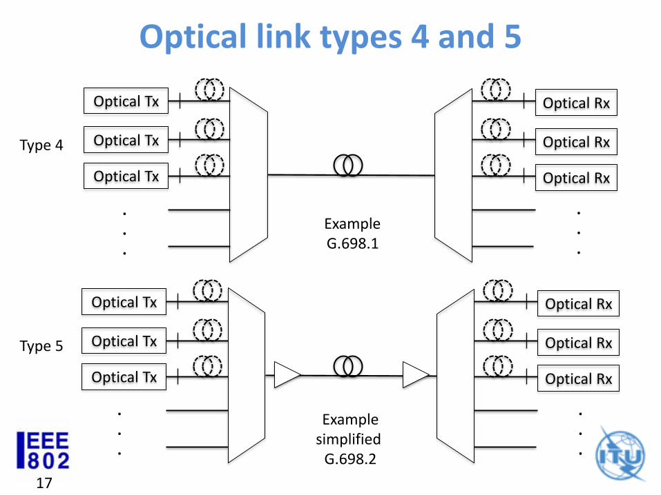
Type 5
Optical Tx Optical Rx
Optical Tx Optical Rx
Optical Tx Optical Rx
.
.
.
.
.
.
Optical link types 4 and 5
Examplesimplified
G.698.2
Type 4
Optical Tx Optical Rx
Optical Tx Optical Rx
Optical Tx Optical Rx
ExampleG.698.1
.
.
.
.
.
.
18
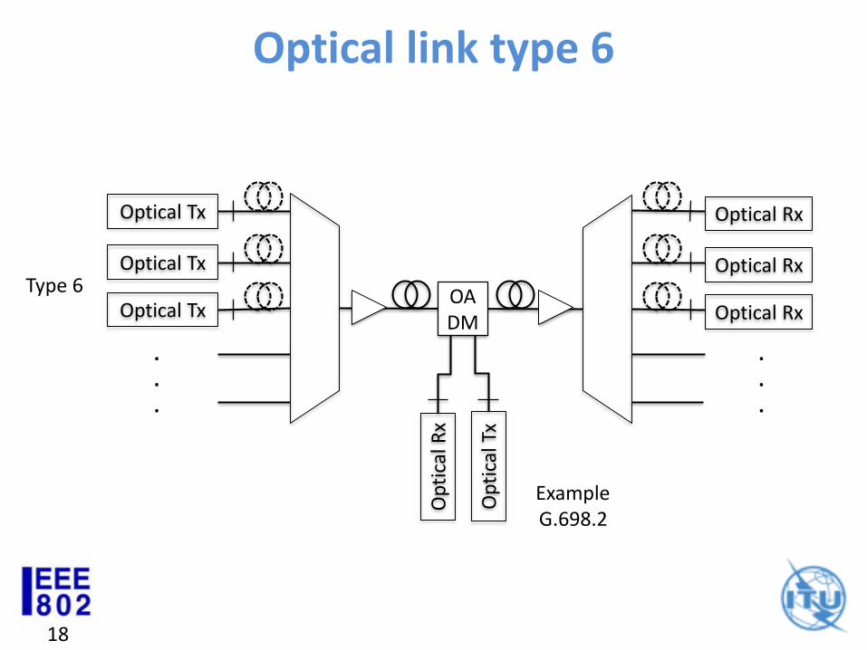
Type 6
ExampleG.698.2
Optical link type 6
Optical Tx Optical Rx
Optical Tx Optical Rx
Optical Tx Optical Rx
.
.
.
.
.
.
OADM
Op
tica
l Tx
Op
tica
l Rx
19
Optical link types vs organizationType IEEE 802.3 ITU-T SG15
1
2
3
4
5
6
ITU-T G.698.2
Bernd Teichmann
Editor of ITU-T G.698.2
Amplified multichannel dense wavelength division multiplexing applications with single channel optical
interfaces
21
DWDM Link
Tx 1
Tx 2
Rx N-1
OM
/OD
SS
SS
RS
RS
SS
Rx 1
Rx 2
Tx N-1
SS
Tx
Y
RS
RS
Rx
X
DWDM Network Elements
OADM
Rx N RS SS
Tx N
OD
/OM
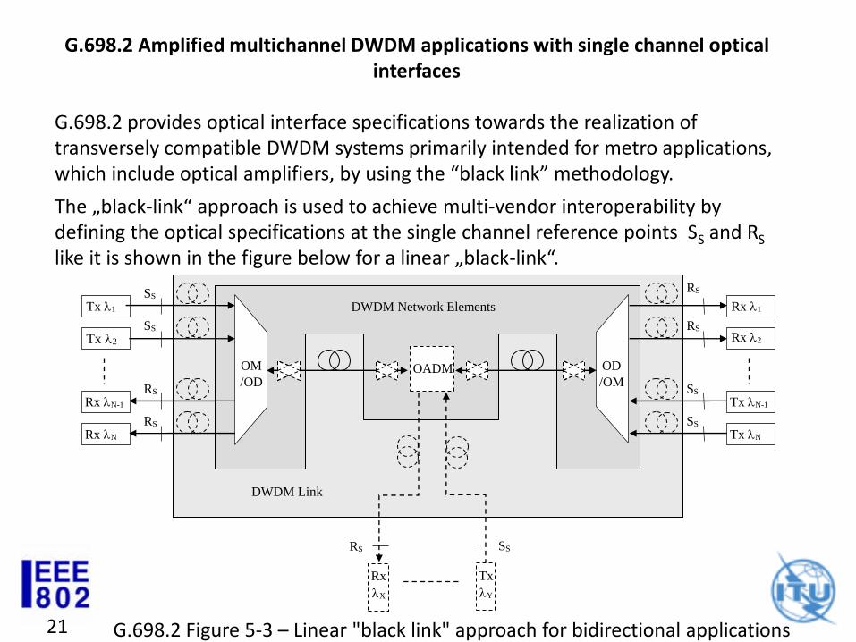
G.698.2 Figure 5-3 – Linear "black link" approach for bidirectional applications
G.698.2 Amplified multichannel DWDM applications with single channel optical interfaces
G.698.2 provides optical interface specifications towards the realization of transversely compatible DWDM systems primarily intended for metro applications, which include optical amplifiers, by using the “black link” methodology.
The „black-link“ approach is used to achieve multi-vendor interoperability by defining the optical specifications at the single channel reference points SS and RS
like it is shown in the figure below for a linear „black-link“.
22
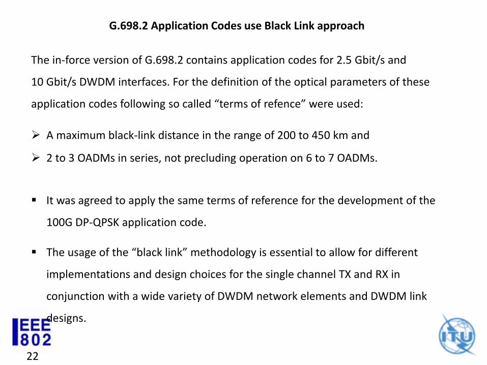
G.698.2 Application Codes use Black Link approach
The in-force version of G.698.2 contains application codes for 2.5 Gbit/s and
10 Gbit/s DWDM interfaces. For the definition of the optical parameters of these
application codes following so called “terms of refence” were used:
A maximum black-link distance in the range of 200 to 450 km and
2 to 3 OADMs in series, not precluding operation on 6 to 7 OADMs.
It was agreed to apply the same terms of reference for the development of the
100G DP-QPSK application code.
The usage of the “black link” methodology is essential to allow for different
implementations and design choices for the single channel TX and RX in
conjunction with a wide variety of DWDM network elements and DWDM link
designs.
23
Black Link specification methodology
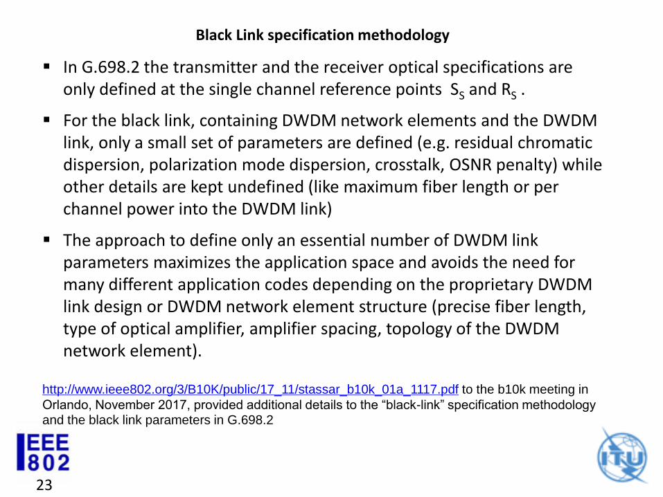
In G.698.2 the transmitter and the receiver optical specifications are only defined at the single channel reference points SS and RS .
For the black link, containing DWDM network elements and the DWDM link, only a small set of parameters are defined (e.g. residual chromatic dispersion, polarization mode dispersion, crosstalk, OSNR penalty) while other details are kept undefined (like maximum fiber length or per channel power into the DWDM link)
The approach to define only an essential number of DWDM link parameters maximizes the application space and avoids the need for many different application codes depending on the proprietary DWDM link design or DWDM network element structure (precise fiber length, type of optical amplifier, amplifier spacing, topology of the DWDM network element).
http://www.ieee802.org/3/B10K/public/17_11/stassar_b10k_01a_1117.pdf to the b10k meeting in
Orlando, November 2017, provided additional details to the “black-link” specification methodology and the black link parameters in G.698.2
MSO Network Evolution
Gary Nicholl, Fernando VillarruelCisco Systems
25
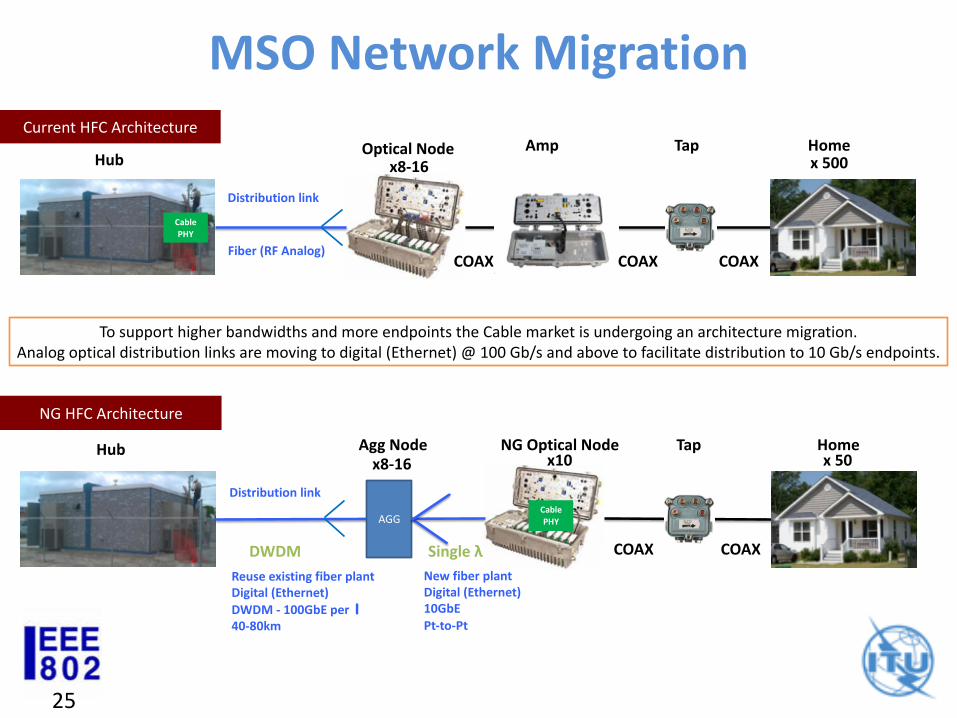
MSO Network MigrationCurrent HFC Architecture
Distribution link
COAX
NG Optical Node
Amp Tap Home
COAX
NG HFC Architecture
COAX COAX
COAX
x 500
DWDM Single λ
AGG
Tap
Optical Node
Agg Node
x8-16
Homex 50x8-16
Reuse existing fiber plantDigital (Ethernet)
DWDM - 100GbE per l
40-80km
Fiber (RF Analog)
Distribution link
New fiber plantDigital (Ethernet)10GbE
Pt-to-Pt
Hub
x10Hub
Cable
PHY
Cable
PHY
To support higher bandwidths and more endpoints the Cable market is undergoing an architecture migration. Analog optical distribution links are moving to digital (Ethernet) @ 100 Gb/s and above to facilitate distribution to 10 Gb/s endpoints.
26
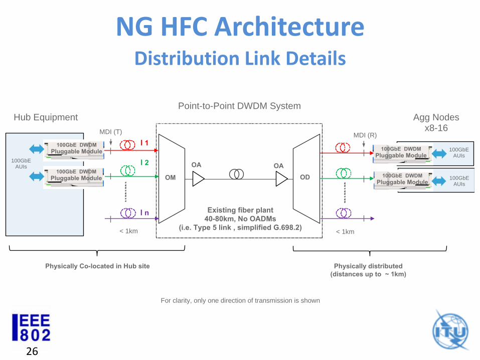
NG HFC Architecture
Hub Equipment
Existing fiber plant
40-80km, No OADMs
(i.e. Type 5 link , simplified G.698.2)
Point-to-Point DWDM System
< 1km
OM
OA OA
OD
l1
l2
ln
Physically Co-located in Hub site
Agg Nodesx8-16
100GbE DWDM
Pluggable Module
For clarity, only one direction of transmission is shown
100GbEAUIs
100GbEAUIs
100GbE DWDM
Pluggable Module
MDI (T)
< 1km
MDI (R)
100GbE DWDM
Pluggable Module 100GbE DWDM
Pluggable Module100GbE
AUIs
Physically distributed
(distances up to ~ 1km)
Distribution Link Details
27
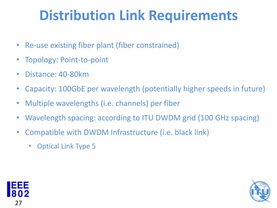
Distribution Link Requirements
• Re-use existing fiber plant (fiber constrained)
• Topology: Point-to-point
• Distance: 40-80km
• Capacity: 100GbE per wavelength (potentially higher speeds in future)
• Multiple wavelengths (i.e. channels) per fiber
• Wavelength spacing: according to ITU DWDM grid (100 GHz spacing)
• Compatible with DWDM Infrastructure (i.e. black link)
• Optical Link Type 5
28
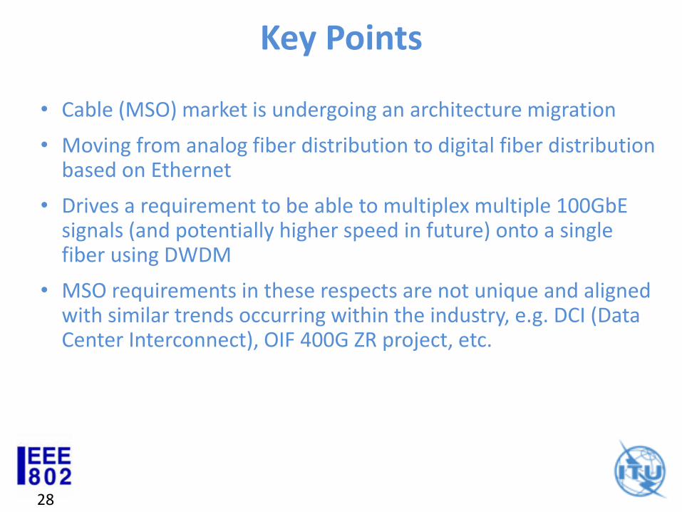
Key Points
• Cable (MSO) market is undergoing an architecture migration
• Moving from analog fiber distribution to digital fiber distribution based on Ethernet
• Drives a requirement to be able to multiplex multiple 100GbE signals (and potentially higher speed in future) onto a single fiber using DWDM
• MSO requirements in these respects are not unique and aligned with similar trends occurring within the industry, e.g. DCI (Data Center Interconnect), OIF 400G ZR project, etc.
Beyond 10 km – Industry Efforts
Jeffery Maki
Juniper Networks
30
Agenda
• Interop Field Trials
• OIF Interoperable 400G
• Form Factor Options
30
31
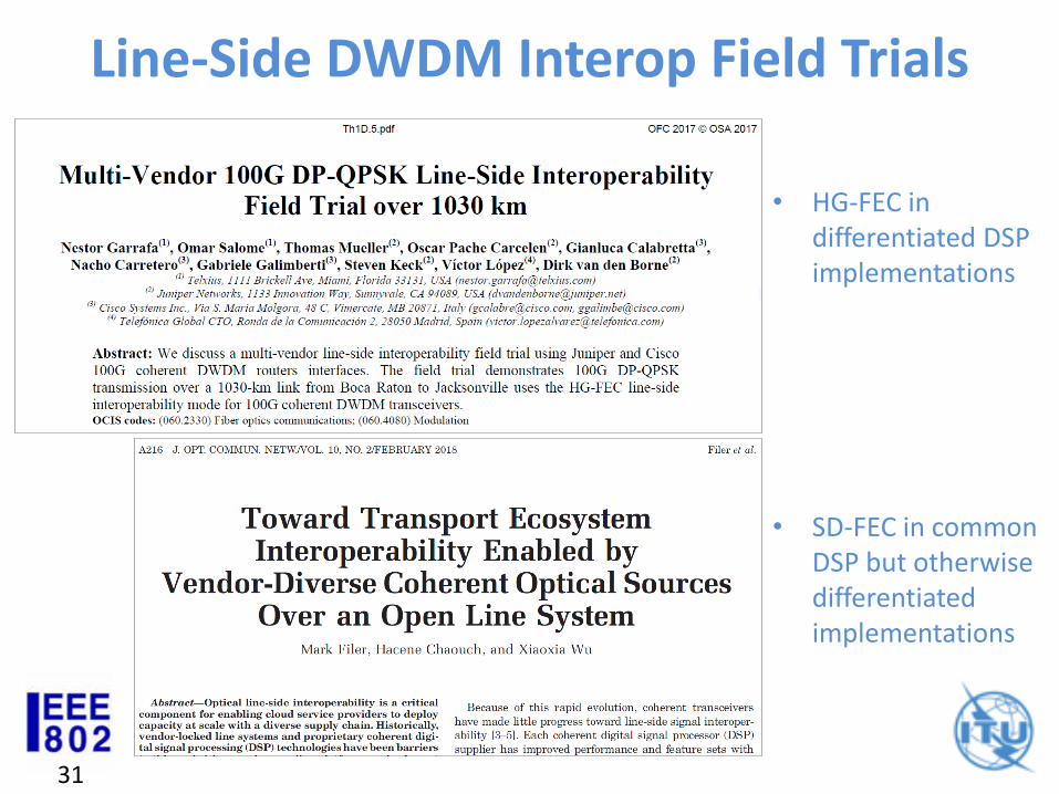
Line-Side DWDM Interop Field Trials
31
• HG-FEC in differentiated DSP implementations
• SD-FEC in common DSP but otherwise differentiated implementations
32
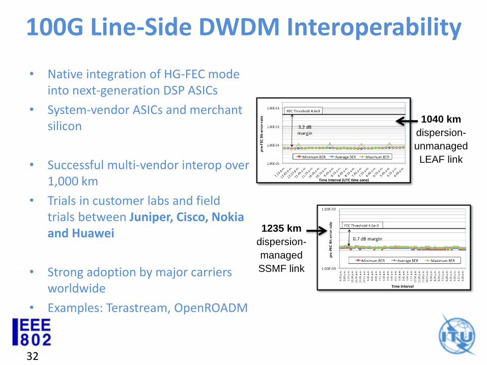
100G Line-Side DWDM Interoperability
• Native integration of HG-FEC mode into next-generation DSP ASICs
• System-vendor ASICs and merchant silicon
• Successful multi-vendor interop over 1,000 km
• Trials in customer labs and field trials between Juniper, Cisco, Nokia and Huawei
• Strong adoption by major carriers worldwide
• Examples: Terastream, OpenROADM
1235 km
dispersion-
managed
SSMF link
1040 km
dispersion-
unmanaged
LEAF link
33
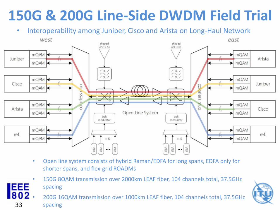
150G & 200G Line-Side DWDM Field Trial• Interoperability among Juniper, Cisco and Arista on Long-Haul Network
• Open line system consists of hybrid Raman/EDFA for long spans, EDFA only for shorter spans, and flex-grid ROADMs
• 150G 8QAM transmission over 2000km LEAF fiber, 104 channels total, 37.5GHz spacing
• 200G 16QAM transmission over 1000km LEAF fiber, 104 channels total, 37.5GHz spacing
34
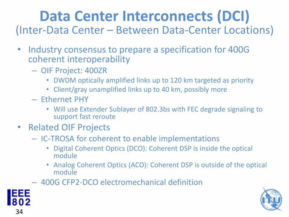
Data Center Interconnects (DCI)
• Industry consensus to prepare a specification for 400G coherent interoperability– OIF Project: 400ZR
• DWDM optically amplified links up to 120 km targeted as priority• Client/gray unamplified links up to 40 km, possibly more
– Ethernet PHY• Will use Extender Sublayer of 802.3bs with FEC degrade signaling to
support fast reroute
• Related OIF Projects– IC-TROSA for coherent to enable implementations
• Digital Coherent Optics (DCO): Coherent DSP is inside the optical module
• Analog Coherent Optics (ACO): Coherent DSP is outside of the optical module
– 400G CFP2-DCO electromechanical definition
(Inter-Data Center – Between Data-Center Locations)
35
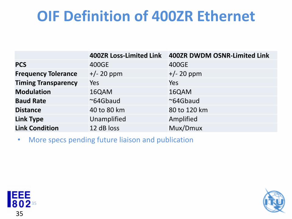
OIF Definition of 400ZR Ethernet
400ZR Loss-Limited Link 400ZR DWDM OSNR-Limited LinkPCS 400GE 400GEFrequency Tolerance +/- 20 ppm +/- 20 ppmTiming Transparency Yes YesModulation 16QAM 16QAMBaud Rate ~64Gbaud ~64GbaudDistance 40 to 80 km 80 to 120 kmLink Type Unamplified AmplifiedLink Condition 12 dB loss Mux/Dmux
35
• More specs pending future liaison and publication
36
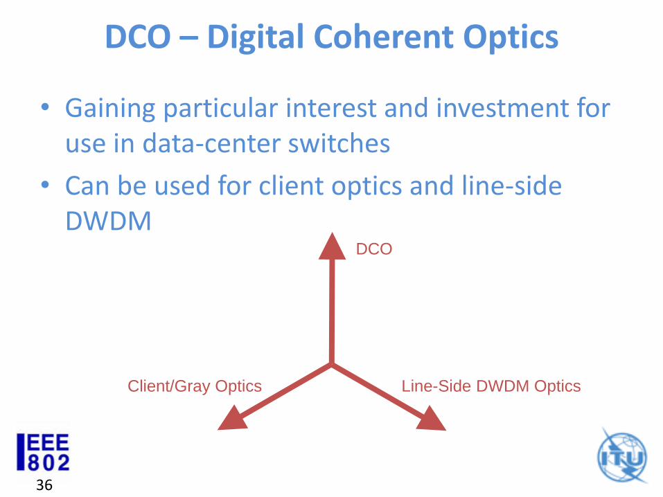
DCO – Digital Coherent Optics
• Gaining particular interest and investment for use in data-center switches
• Can be used for client optics and line-side DWDM
Client/Gray Optics
DCO
Line-Side DWDM Optics
37
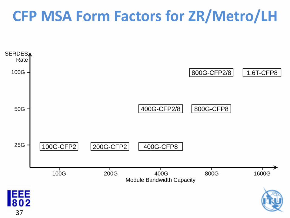
CFP MSA Form Factors for ZR/Metro/LH
SERDESRate
100G
50G
25G
Module Bandwidth Capacity200G 400G 800G 1600G
200G-CFP2
400G-CFP2/8 800G-CFP8
100G
100G-CFP2 400G-CFP8
1.6T-CFP8800G-CFP2/8
38
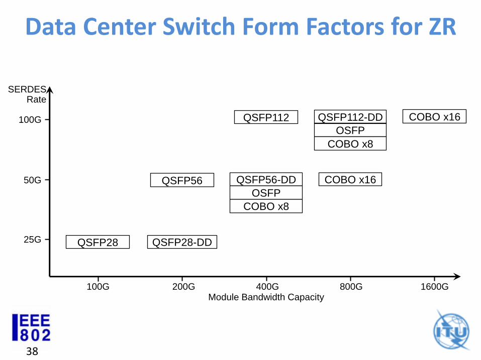
Data Center Switch Form Factors for ZR
SERDESRate
100G
50G
25G
Module Bandwidth Capacity200G 400G 800G 1600G
SFP
28- DD
QSFP28
100G
OSFP
QSFP28-DD
QSFP56
QSFP112
COBO x16
COBO x8
COBO x16QSFP112-DD
OSFP
COBO x8
QSFP56-DD
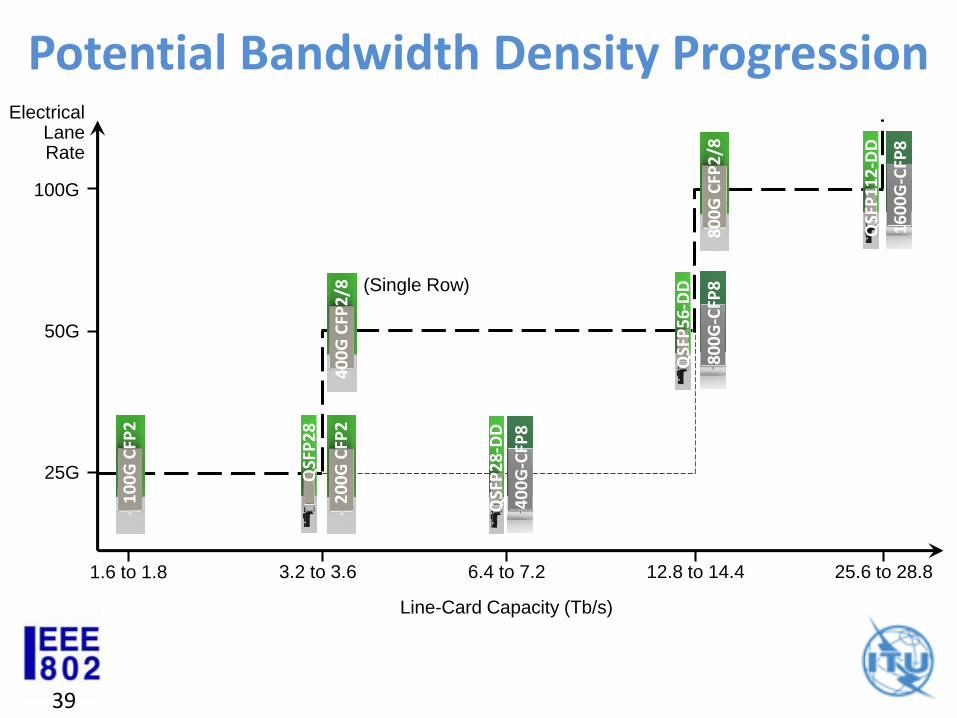
39
Potential Bandwidth Density ProgressionElectrical
Lane Rate
100G
50G
25G
Line-Card Capacity (Tb/s)
3.2 to 3.6 6.4 to 7.2 12.8 to 14.4 25.6 to 28.8
QSF
P2
8
QSF
P2
8-D
D
QSF
P5
6-D
D
SFP
28
-DD
40
0G
-CFP
8
1.6 to 1.8
10
0G
CFP
2
20
0G
CFP
2
80
0G
-CFP
8
40
0G
CFP
2/8 (Single Row)
QSF
P1
12
-DD
16
00
G-C
FP8
80
0G
CFP
2/8

Discussion