Embed Size (px)
Citation preview

Bulk Metal® Foil Technology Ultra High Precision Trimming Potentiometers, 1/4" Square, RJ26 Style, Designed to Meet or Exceed The Requirements of
MIL-PRF-39035, Char. H with a Smooth and Unidirectional Output
Accutrim™ 1240 (RJ26 Style)
INTRODUCTIONVishay Foil Resistors’ (VFR) precision trimmers have the Bulk Metal® Foil resistive element which possesses a unique inherent temperature and load life stability. Plus, their advanced virtually back lash-free adjustment mechanism makes them easy to set quickly and accurately and keeps the setting exactly on target.
FEATURES Temperature coefficient of resistance (TCR):
± 10 ppm/°C. (- 55 °C to + 150 °C ref. at + 25 °C); through the wiper (3); ± 25 ppm/°C (see table 2 for low values)
A smooth and unidirectional resistance with leadscrew adjustment
Load life stability: 0.1 % typical R, 1.0 % maximum R under full rated power at + 85 °C for 10 000 h
Settability: 0.05 % typical; 0.1 % maximum Setting stability: 0.1 % typical; 0.5 % maximum, DSS Power rating: 0.25 W at + 85 °C Resistance range: 5 to 10 k Tolerance: ± 5 %, ± 10 % Electrostatic discharge (ESD) at least to 25 kV Terminal finish: gold plated (tin/lead finish is available on
request)
CERMET
Wiper TravelR
esis
tan
ceWiper Travel
Res
ista
nce
BULK METALFOIL WIREWOUND
Wiper Travel
Res
ista
nce
TABLE 1 - MODEL SELECTIONMODEL TERMINATION STYLE AVERAGE WEIGHT (g) POWER RATING at + 85 °C AMBIENT NO. OF TURNS
1240W-edge mount, top adjust
0.4 0.25 W 21 ± 2X-edge mount, side adjustP-horizontal mount, side adjust
Note• See Figure 1, next page
TABLE 2 - 1240 (RJ26) SERIES ELECTRICAL SPECIFICATIONS
Temperature Coefficient ofResistance (TCR) 50 to 10 k
± 10 ppm/°C maximum(- 55 °C to + 150 °C,+ 25 °C ref.)End-to-end (2)
Temperature Coefficient ofResistance 5, 10 and 20
± 20 ppm/°C
Through the wiper (3) ± 25 ppm/°CStabilityLoad life at 10 000 hEnd-to-end (2)
0.1 % typical R1.0 % maximum R(under full rated power of 0.25 W at + 85 °C)
Power Rating (4) 0.25 W at + 85 °CSettability 0.05 % typical;
0.1 % maximumSetting Stability 0.1 % typical;
0.5 % maximumContact ResistanceVariation - CRV (noise) (5)
3 typical; 10 maximum
Hop-off 0.25 % typical;1.0 % maximum
High-Frequency OperationRise timeInductanceCapacitance
1.0 ns without ringing0.08 µH typical0.5 pF typical
Operating Temperature Range - 55 °C to + 150 °C
TABLE 3 - VALUES VS. TOLERANCES
STANDARD RESISTANCE VALUES(in )
STANDARDTOLERANCE
5, 10 ± 10 %
20, 50, 100, 200, 500, 1K, 2K, 5K, 10K ± 5 %
TABLE 4 - MECHANICAL SPECIFICATIONSAdjustment Turns 21 ± 2
Mechanical Stops Wiper idles - no discontinuity
Internal Terminations All welded - no flux
Case Material1240X - diallyl-phthalate: green (DAP)1240W - diallyl-phthalate: green (DAP)1240P - thermoplastic: black
Shaft Torque 3 oz. in. maximum
Backlash 0.005 % typical
Document Number: 63053 For any questions, contact www.vishayfoilresistors.comRevision: 2-Mar-15 [email protected] 1
Accutrim™ 1240 (RJ26 Style)
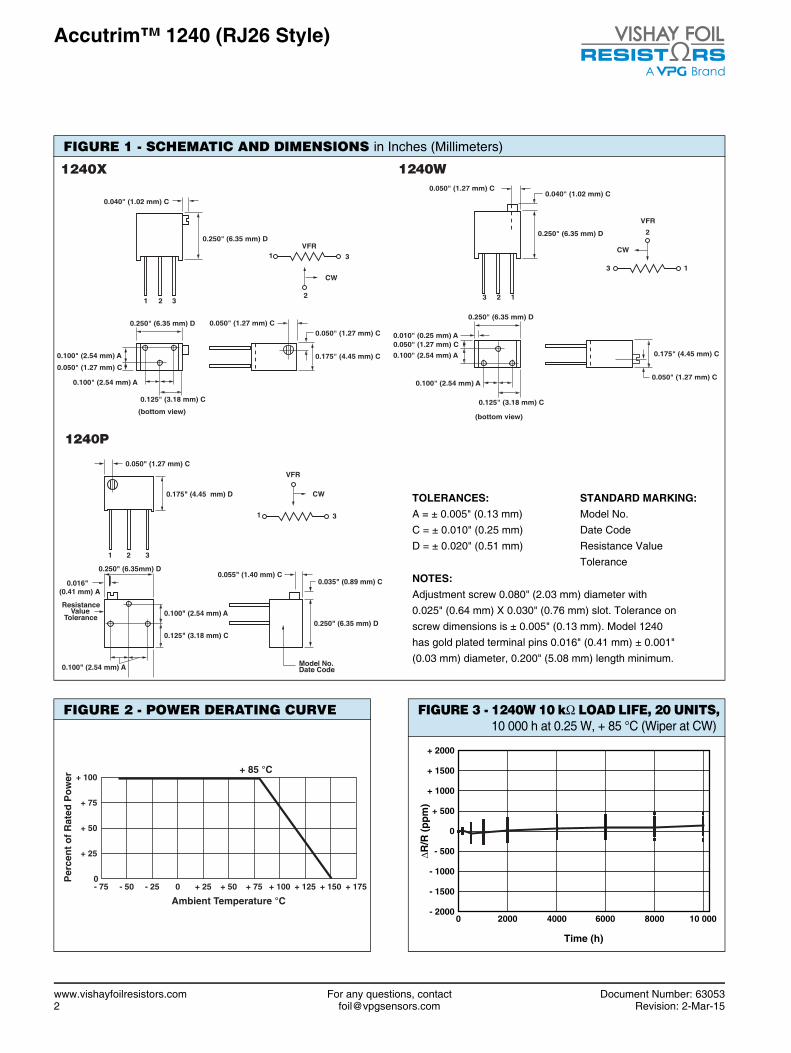
FIGURE 2 - POWER DERATING CURVE
Ambient Temperature °C
+ 85 °C+ 100
+ 75
+ 50
+ 25
0Per
cen
t o
f R
ated
Po
wer
- 75 + 150+ 125+ 100+ 75+ 50+ 250- 25- 50 + 175
FIGURE 3 - 1240W 10 k LOAD LIFE, 20 UNITS, 10 000 h at 0.25 W, + 85 °C (Wiper at CW)
+ 2000
+ 1500
+ 1000
+ 500
0
- 500
- 1000
- 1500
- 2000
ΔR/R
(p
pm
)
Time (h)
0 2000 4000 8000 10 0006000
FIGURE 1 - SCHEMATIC AND DIMENSIONS in Inches (Millimeters)
1240X
0.050" (1.27 mm) C
0.040" (1.02 mm) C
VFR
2
31
CW
0.250" (6.35 mm) D
1 2 3
0.250" (6.35 mm) D
0.100" (2.54 mm) A
0.100" (2.54 mm) A
0.050" (1.27 mm) C
0.050" (1.27 mm) C
0.175" (4.45 mm) C
0.125" (3.18 mm) C
(bottom view)
1240W
3 12
0.050" (1.27 mm) C
VFR
2
13
CW
0.250" (6.35 mm) D
0.250" (6.35 mm) D
0.100" (2.54 mm) A
0.100" (2.54 mm) A
0.050" (1.27 mm) C
0.050" (1.27 mm) C
0.175" (4.45 mm) C
0.125" (3.18 mm) C
0.040" (1.02 mm) C
0.010" (0.25 mm) A
(bottom view)
ResistanceValue
Tolerance
0.055" (1.40 mm) C
0.050" (1.27 mm) C
VFR
31
CW0.175" (4.45 mm) D
1 2 3
0.250" (6.35mm) D
0.100" (2.54 mm) A
0.100" (2.54 mm) A
0.035" (0.89 mm) C
0.250" (6.35 mm) D
0.125" (3.18 mm) C
Model No.Date Code
0.016"(0.41 mm) A
1240P
TOLERANCES:A = ± 0.005" (0.13 mm)C = ± 0.010" (0.25 mm)D = ± 0.020" (0.51 mm)
STANDARD MARKING:Model No.Date CodeResistance ValueTolerance
NOTES:Adjustment screw 0.080" (2.03 mm) diameter with 0.025" (0.64 mm) X 0.030" (0.76 mm) slot. Tolerance onscrew dimensions is ± 0.005" (0.13 mm). Model 1240has gold plated terminal pins 0.016" (0.41 mm) ± 0.001"(0.03 mm) diameter, 0.200" (5.08 mm) length minimum.
www.vishayfoilresistors.com For any questions, contact Document Number: 630532 [email protected] Revision: 2-Mar-15

Accutrim™ 1240 (RJ26 Style)
TABLE 5 - COMPARISONMIL-PRF-39035/3 CHARACTERISTIC H MODEL 1240 MAXIMUM(6)
TEST GROUP IConditioningContact resistance variation - CRV (noise)Immersion
± 1.0 %± 3.0 % or 3 (7)
No continuous stream of bubbles
± 0.5 %3 typical, 10 maximum
No continuous stream of bubblesTEST GROUP I aVisual and mechanicalActual effective electrical travelEnd resistanceDielectric withstanding voltage - DWVPer MIL-STD-202, methods 301 and 105Atmospheric pressureBarometric pressureInsulation resistanceShaft torqueThermal shockSetting stability
No failures10 to 25 turns2 % or 2 (7)
600 VAC, 1 min250 VAC, 1 min 1000 M
3 oz. in. maximum± 1.0 %± 1.0 %
No failures21 ± 2 turns
2 for values 1 k;5 for values 2 k;
600 VAC, 1 min250 VAC, 1 min
> 1000 M3 oz. in. maximum
± 0.5 %± 0.5 %
TEST GROUP IISolderability Per MIL-STD-202, method 208 Per MIL-STD-202, method 208TEST GROUP IIIResistance temperature characteristic - TCRMoisture resistanceContact resistance variation - CRV (noise)
± 0.005 %/°C (± 50 ppm/°C)± 1.0 %
3.0 % or 3 (7)
± 0.001 %/°C (± 10 ppm/°C)± 0.5 %
3 typical, 10 maximumTEST GROUP IVSettabilityShockSetting stabilityVibrationSetting stabilityContact resistance variation - CRV (noise)Salt spray
± 1.0 %± 1.0 %± 1.0 %± 1.0 %± 1.0 %
3.0 % or 3 (7)
No corrosion
± 0.1 %± 0.5 %± 0.5 %± 0.5 %± 0.5 %
3 typical, 10 maximumNo corrosion
TEST GROUP VSolder heatLow-temperature operationSetting stabilityLow-temperature storageHigh-temperature exposureSetting stabilityContact resistance variation - CRV (noise)Integrity of shaft
± 1.0 %± 1.0 %± 2.0 %± 1.0 %± 3.0 %± 2.0 %
3 % or 3 (7)
No loosening or breakage
± 0.1 %± 0.5 %± 0.5 %± 0.5 %± 0.5 %± 0.5 %
3 typical, 10 maximumNo loosening or breakage
TEST GROUP VIRotational life (200 cycles)Contact resistance variation - CRV (noise)Terminal strength
± 2.0 %3 % or 3 (7)
2 lbs.
± 2.0 %3 typical, 10 maximum
2 lbs.TEST GROUP VIILife (2000 h) at + 85 °CLife (10 000 h) at + 85 °C
± 3.0 %± 5.0 %
± 0.1 % typical, ± 1.0 % maximum± 0.1 % typical, ± 1.0 % maximum
TEST GROUP VIIISolvent resistance No failures No failures
Notes(1) Maximum is 1.0 % A.Q.L. standard for all specifications except
TCR. (For TCR information, see notes 2 and 3.)(2) Maximum TCR applies to the 3 (sigma) limit or 99.73 % of a
production lot. (Measured end-to-end with wiper off the element.)(3) Measurements of TCR through the wiper are influenced more by
setting stability and the percentage of the total resistance in use (at the wiper) than by fundamental resistance change due to temperature alone. The parameter shown in table 2 is a 2 s distribution typifying the behavior of the device when used with 40 % or more of the total resistance in use.
(4) Derated linearly for full power at + 85 °C to zero power at + 150 °C. See Figure 2 on previous page.
(5) Independent of resistance value. 3 maximum available on special request.
(6) All R’s are measured to the tolerance specified + 0.01 .(7) Whichever is greater.
Special Available Options:Special markingBurn-in and screening operations.
VFR TRIMMERS ARE INSPECTED100 % for:• Immersion• Resistance tolerance check• End resistance• Visual-mechanical• Dynamic tests for continuity, CRV
By sample for:• TCR• DWV
Document Number: 63053 For any questions, contact www.vishayfoilresistors.comRevision: 2-Mar-15 [email protected] 3

Accutrim™ 1240 (RJ26 Style)
TABLE 6 - GLOBAL PART NUMBER INFORMATIONNEW GLOBAL PART NUMBER: Y4053500R000J0L (preferred part number format)
DENOTES PRECISION VALUE CHARACTERISTICS (1)
Y R = K = k
0 = gold plated termination (lead (Pb)-free)1 to 999 = custom
PRODUCT CODE TOLERANCE PACKAGING
4053 = 1240W5053 = 1240X0053 = 1240P
J = ± 5 %K = ± 10 %
L = foam/box pack
FOR EXAMPLE: ABOVE GLOBAL ORDER Y4053 500R000 J 0 L:TYPE: 1240WVALUE: 500.0 ABSOLUTE TOLERANCE: ± 5.0 %TERMINATION: gold plated termination (lead (Pb)-free)PACKAGING: foam/box pack
HISTORICAL PART NUMBER: 1240W 500R00 J B (will continue to be used)
1240W 500R00 J B
MODEL RESISTANCE VALUE TOLERANCE PACKAGING
1240W1240X1240P
500R00 = 500.0 J = ± 5 %K = ± 10 %
B = foam/box pack
Note(1) For non-standard requests, please contact application engineering.
0 5 3 5 0 R 00Y 4 J 00 L0
www.vishayfoilresistors.com For any questions, contact Document Number: 630534 [email protected] Revision: 2-Mar-15
Vishay Precision Group, Inc.
www.vpgsensors.com1
Legal Disclaimer Notice
Document No.: 63999Revision: 15-Jul-2014
DisclaimerALL PRODUCTS, PRODUCT SPECIFICATIONS AND DATA ARE SUBJECT TO CHANGE WITHOUT NOTICE.
Vishay Precision Group, Inc., its affiliates, agents, and employees, and all persons acting on its or their behalf (collectively, “VPG”), disclaim any and all liability for any errors, inaccuracies or incompleteness contained herein or in any other disclosure relating to any product.
The product specifications do not expand or otherwise modify VPG’s terms and conditions of purchase, including but not limited to, the warranty expressed therein.
VPG makes no warranty, representation or guarantee other than as set forth in the terms and conditions of purchase. To the maximum extent permitted by applicable law, VPG disclaims (i) any and all liability arising out of the application or use of any product, (ii) any and all liability, including without limitation special, consequential or incidental damages, and (iii) any and all implied warranties, including warranties of fitness for particular purpose, non-infringement and merchantability.
Information provided in datasheets and/or specifications may vary from actual results in different applications and performance may vary over time. Statements regarding the suitability of products for certain types of applications are based on VPG’s knowledge of typical requirements that are often placed on VPG products. It is the customer’s responsibility to validate that a particular product with the properties described in the product specification is suitable for use in a particular application. You should ensure you have the current version of the relevant information by contacting VPG prior to performing installation or use of the product, such as on our website at vpgsensors.com.
No license, express, implied, or otherwise, to any intellectual property rights is granted by this document, or by any conduct of VPG.
The products shown herein are not designed for use in life-saving or life-sustaining applications unless otherwise expressly indicated. Customers using or selling VPG products not expressly indicated for use in such applications do so entirely at their own risk and agree to fully indemnify VPG for any damages arising or resulting from such use or sale. Please contact authorized VPG personnel to obtain written terms and conditions regarding products designed for such applications.
Product names and markings noted herein may be trademarks of their respective owners.
Copyright Vishay Precision Group, Inc., 2014. All rights reserved.
Disclaimer
Legal Disclaimer Notice