Embed Size (px)
Citation preview

J-STAGE Advance Publication date: 27 October, 2016Paper No.16-00342
© 2016 The Japan Society of Mechanical Engineers[DOI: 10.1299/mej.16-00342]
Vol.3, No.6, 2016Bulletin of the JSME
Mechanical Engineering Journal
0123456789
1. Introduction
Operational results of oxyfuel power plant (Callide Oxyfuel Project)
Akihiro KOMAKI*, Takahiro GOTO*, Terutoshi UCHIDA*, Toshihiko YAMADA*, Takashi KIGA* and Chris SPERO**
*IHI Corporation, Business Development department, Energy & Plant Operations
Toyosu IHI Building, 1-1, Toyosu 3-chome, Koto-ku, Tokyo 135-8710, Japan
E-mail: [email protected]
1
Abstract In 2013, CO2 levels surpassed 400 ppm for the first time in recorded history. So, we are facing global warming due to the increase levels of atmospheric carbon dioxide (CO2). As a method of reducing CO2 emissions from the thermal power plants, there are carbon dioxide capture and storage (CCS) technologies. Oxyfuel combustion is one of the CO2 Capture technologies and IHI have developed it since 1989. Then, Callide Oxyfuel Project commenced to apply oxyfiring technology in an existing coal fired power plant and to demonstrate an oxyfuel power plant in March, 2008. Demonstration began in 2012 after existing boiler was retrofitted. During the demonstration for approximately three years, many tests were conducted and many data were collected for commercial use. As a result, we confirmed characteristics of oxyfiring such as total heat absorption, combustion characteristics, emissions of NOx, SOx, carbon-in-ash, operational flexibility from 15MWe (50%L) to 30MWe (100%L) and behavior of injected CO2 at the injection site. Total heat absorption of the boiler under oxyfiring was 2 to 3MW higher because of decreasing heat loss in flue gas and rising temperature of boiler feed water by a flue gas cooler. NO was decomposed in the furnace under oxyfiring because flue gas was recirculated. On the other hand, reaction between SO2 and absorbent such as Ca, Mg in ash was not so active regardless of high concentrated SO2 under oxyfiring. Carbon-in-ash was almost 40%~70% in oxyfirng compared with in airfiring because of longer residence time in the furnace. Operational flexibility is important to control oxyfiring operation and it was confirmed that oxyfiring can be operated as well as airfiring. In this paper, operational results are presented in Callide Oxyfuel Project.
Key words : Coal, CCS, Oxyfuel, Oxyfiring, CO2, Power plant, Oxy-combustion, Callide, Australia
**CS Energy, Callide Oxyfuel Services, CS Energy Ltd, Level2, HQ North Tower 540 Wickham Street Fortitude Valley GPO Box 769 Brisbane Qld 4001, Australia
In 2013, CO2 levels surpassed 400 ppm for the first time in recorded history. Coal fired power plants are considered one of the resources to emit the large amount of CO2. According to “World Energy Outlook 2014” (IEA), coal use in Non-OECD countries will increase up to about three times in 2040 as compared with 1990. Therefore, reducing CO2
concentration in the atmosphere is an important and urgent issue, so the world is focusing on countermeasures. Coal fired power plants still discharge more CO2 emissions during the combustion process than any other fossil fuel power generation plants. Coal is a stable primary energy resource for power generation and will remain as a key energy resource in the future. Therefore, CO2 emissions from coal-fired power plants must be reduced.
Recently, many CO2 capturing processes’ which are applied to coal-fired power plants have been developed, such as post-combustion capture and pre-combustion capture. Oxyfuel combustion is also a potential candidate for capturing CO2 from coal-fired power plants. IHI have developed oxyfuel combustion technology since 1989, and a feasibility study on the demonstration project between Australia and Japan started in 2004, followed by the Callide Oxyfuel Project which commenced to demonstrate oxyfuel power plant in 2008.
Received 1 June 2016

2
Komaki, Goto, Uchida, Yamada, Kiga and Spero, Mechanical Engineering Journal, Vol.3, No.6 (2016)
© 2016 The Japan Society of Mechanical Engineers[DOI: 10.1299/mej.16-00342]
During the demonstration, many tests were conducted and many data were collected. Through this project, we
confirmed the operational flexibility, improved plant efficiency, CO2 concentration in flue gas, flame stability, and
combustion characteristics such as decrease of carbon-in-ash and NO in flue gas etc., under oxyfiring.
In this paper, the operational results of the 30MWe oxyfuel power plant after approximately three years
demonstration at the Callide Oxyfuel Project are introduced.
2. Outline of the oxyfiring system
In oxyfiring system, O2 is separated from the air by Air Separation Unit (ASU) and supplied to the boiler for coal
combustion. Moreover, the flue gas from the boiler is recirculated and mixed with O2 in order to use conventional
airfiring technology. Accordingly, the oxyfiring flue gas is emitted mainly comprises of CO2 and H2O, and will
theoretically enhance the CO2 concentration in flue gas up to more than 90 dry%. The overall CCS concept using an
oxyfiring system is shown in Fig.1.
The method for capturing almost pure CO2 involves removing H2O and separating non-condensable gases from the
oxyfuel gas via a CO2 compression and purification unit (CPU).
The characteristics of oxyfiring technology are as follows:
Highly-concentrated CO2 can be captured directly from flue gas, because N2 is removed before combustion.
Efficiency of oxyfuel boiler is far higher than that of an airfiring boiler under the same conditions, because the
amount of flue gas is decreased (by approximately one-fifth). The feed-water system can also be integrated
with the flue gas system for heat recovery, making it even more efficient.
NOx emissions are reduced, because recirculation gas is supplied to a furnace and the NOx in the
recirculation gas is decomposed. Moreover, NOx can be removed at the CPU.
Enriched O2 and increasing residence time in the coal combustion process can reduce carbon-in-ash.
The system can be applied to existing power plants as well as new construction power plants.
Fig.1 Concept of the oxyfiring system
The oxyfiring system plays a significant role as an optional technology for capturing CO2 from coal-fired power
plants. This technology is a focus in many countries and they have conducted research and development to realize the
commercial oxyfuel power plants.
3. Callide Oxyfuel Project
Callide Oxyfuel Project in central Queensland, Australia, was established in 2008. Callide-A, which was a retrofit
of an existing power plant with a capacity of 30MWe, was the largest operating oxyfuel power plant in the world that
sold electricity to Australia. This was achieved with funding from the Australian and Japanese governments, the
Queensland state Government, and was followed by research results from 1989 in Japan. Before Callide Oxyfuel
Project commenced, various evaluations were conducted regarding oxyfiring for realizing demonstration at Callide-A
such as combustion characteristics, heat transfer, ignition and safety and so on. These results are shown in the other
paper (Yamada et al., 2010).
Fabric filter
CO2 storage site
Air
(N2,O2)
ASU
Coal
Re-circulation gas
O2
Non-condensable gas
N2
CPU
Transportation CO2 injection facility
P
Boiler
2

2
Komaki, Goto, Uchida, Yamada, Kiga and Spero, Mechanical Engineering Journal, Vol.3, No.6 (2016)
© 2016 The Japan Society of Mechanical Engineers[DOI: 10.1299/mej.16-00342]
The project milestones to date are shown in Table 1. The overview of Callide-A power plant is shown in Fig.2 and
the oxyfiring process in Callide-A is shown in Fig.3. The specification of Callide-A boiler was written in the paper
(Komaki et al., 2013).
This project was composed of three stages. In stage 1, the existing boiler was retrofitted to an oxyfuel boiler. The
ASU and the CPU were installed. In stage 2, the CO2 captured by oxyfiring system was transported by truck and stored
underground. In stage 3, the project outcomes have been summarized including the data which had been acquired
through the operation. The objectives of stage 1 involved analyzing the design and cost data so that it could be applied
to existing plants, and accumulating operational experience, as well as demonstrating the oxyfuel boiler system and
CPU.
The oxyfuel power plant was demonstrated and the various tests were performed from March 2012 to March 2015.
The CO2 captured from the oxyfuel power plant was transported and injected into the storage layer.
Fig.2 Overview of Callide-A power station
Table 1 Milestones of the Callide Oxyfuel Project
Month, Year Course
2004 Feasibility study of the Callide oxyfuel Project commenced.
March, 2006 MoU (Memorandum of Understanding) signed
October, 2006 Australian Government’s Low-emission Technology Demonstration Fund funding announcement
March, 2008 Callide Oxyfuel Project Joint Venture agreements finalized
August, 2008 Refurbishment of Unit A4 at Callide-A Power Station commenced
October, 2008 Official launch of the Callide Oxyfuel Project
January, 2009 Refurbishment of Unit A4 at Callide A Power Station completed
October, 2009 Earthworks commenced at Callide A Power Station
January, 2010 Earthworks completed and foundation excavations commenced at Callide A Power Station
March, 2011 Boiler modification completed for oxyfiring at Callide A Power Station
April, 2011 First coal firing in air mode after boiler oxyfiring modifications
March, 2012 First boiler operation in full oxyfiring mode
December, 2012 Demonstration phase began
February, 2015 Oxyfuel operation of 10,000 hours achieved
March, 2015 Demonstration phase completed
3

2
Komaki, Goto, Uchida, Yamada, Kiga and Spero, Mechanical Engineering Journal, Vol.3, No.6 (2016)
© 2016 The Japan Society of Mechanical Engineers[DOI: 10.1299/mej.16-00342]
Fig.3 Oxyfiring process in Callide-A
4. Operational results of the oxyfuel power plant
The Project team operated the oxyfiring power plant for approximately three years from March 2012 when O2 was
characteristics of the oxyfuel boiler were confirmed. This section introduces the major results of the oxyfuel boiler in
demonstration. Many tests were conducted in order to confirm the characteristics of oxyfuel boiler by using different
mill configuration, loads, O2 concentration in total gas (inlet O2 concentration) and so on. The results from the
demonstration of the oxyfuel boiler are shown as follows.
Operational flexibility
Combustion in various coal
Load ramp up & down test
Turn-down test
Optimization of mode transition
Confirmation of boiler performance
30MWe operation at both airfiring and oxyfiring
Various boiler inlet- O2
Direct- O2 injection to the flame
Bypass operation of dehydration device
Simulated staging combustion
Exposure test of boiler tubes for high temperature and materials for low temperature
Reliability
Operation hours
Inspection of equipment
As a result of demonstration, Callide-A achieved the strong track records as follows.
Total generation: 14,800 hours
Oxyfuel operation: 10,200 hours
CO2 capture operation: 5,600 hours
Coal burned: 320,000 tones
4.1 Total heat absorption of oxyfuel boiler
The amount of flue gas through the burners is approximately 70% under oxyfiring compared with airfiring. Heat
absorption is defined as heat transferred from radiation and convection. Total heat absorption of the boiler is included
furnace, 1SH, evaporator and 2SH. It was 2 to 3 MW higher under oxyfiring, because heat loss of flue gas was
decreased and heat of flue gas was recovered in order to raise temperature of boiler feed water by a flue gas cooler.
Therefore, plant efficiency under oxyfiring was enhanced. Then, there was no significant difference regarding
convection between the bank and the furnace under both airfiring and oxyfiring. These results were almost the same by
combustion test facilities and simulation at the stage of feasibility study before the operation (Yamada et al., 2007).
4
supplied to the boiler. Initial operation results are referred to the other paper (Komaki et al., 2013). Then, various basic

2
Komaki, Goto, Uchida, Yamada, Kiga and Spero, Mechanical Engineering Journal, Vol.3, No.6 (2016)
© 2016 The Japan Society of Mechanical Engineers[DOI: 10.1299/mej.16-00342]
4.2 Combustion characteristics
oxyfiring respectively. Figure 4 shows the weighted average value of carbon-in-ash of each hopper after burning
blended bituminous coal and every ash from 13 hoppers was sampled and analyzed. Regarding “Oxyfiring+direct-O2”
data in Coal B and D was not obtained. In Callide-A, two O2 lances for each burner were what we call direct-O2
installed in order to evaluate the effect of supplying pure O2 near the burners. The maximum capacity was set about
10% of total O2 which was supplied to the boiler. From the test results of direct-O2 injection test, carbon-in-ash in
oxyfiring with direct-O2 was further decreased compared with airfiring and oxyfiring, carbon-in-ash was almost
40%~70% in oxyfirng compared with in airfiring because of the longer residence time in the furnace for the small
amount of flue gas. In the meantime, in Fig.5, corrective
value to 12% CO2 of NO and SO2 were used in order to
compare on the basis of emissions amount. Conditions of
flue gas O2 concentration at the boiler exit during the tests
were the same in oxyfiring as in airfiring. The NOcorr, with
a 12% CO2 corrective value, declines around 60% with
oxyfiring because NO was decomposed in recirculated flue
gas in the furnace. In fact, it was reported in the research
paper (Okazaki and Ando, 1997) that the effect of a
reduction of recycled NO in the furnace was dominant and
more than 50% of recycled NO was reduced to become N2
through the chemical reaction in the combustion zone. This
means NOcorr emissions can be reduced in the oxyfiring.
In oxyfiring, the source of NOx is mainly fuel NOx and
thermal NOx by air leakage into the boiler.
On the other hand, SO2 in recirculated flue gas was not
so different between airfiring and oxyfiring from the Fig.5.
This means SO2 under oxyfiring is much more concentrated
than under airfiring. Reaction between SO2 and absorbent such as Ca, Mg in ash was not so active regardless of high
concentrated SO2 under oxyfiring. From this result, DeSOx facility needs to be installed if there is trouble regarding
SO2.
Fig.5 Difference of combustion characteristics between airfiring and oxyfiring
0
100
200
300
400
500
600
700
800
14 16 18 20 22 24 26 28 30 32
Sta
ck i
nle
t N
O c
orr
. (p
pm
)
Generator (MW)
Airfiring
Oxyfiring
0
50
100
150
200
250
300
350
14 16 18 20 22 24 26 28 30 32
Sta
ck i
nle
t S
O2 c
orr
. (p
pm
)
Generator (MW)
Airfiring
OxyfiringNOcorr = NO x 12 / CO
2 SO
2corr = SO
2 x 12 / CO
2
5
0
20
40
60
80
100
120
Coal A Coal B Coal C Coal D
AirfiringOxyfiringOxyfiring+direct-O2
Rel
ativ
e va
lue
of c
arbo
n-in
-ash
(-)
Fig.4 Carbon-in-ash in various coal and conditions
Direct-O2
Figure 4 and 5 show carbon-in-ash and the combustion characteristics about NOx, SOx in both airfiring and

2
Komaki, Goto, Uchida, Yamada, Kiga and Spero, Mechanical Engineering Journal, Vol.3, No.6 (2016)
© 2016 The Japan Society of Mechanical Engineers[DOI: 10.1299/mej.16-00342]
4.3 Various boiler inlet O2 tests
The various boiler inlet O2 operations were conducted to
check operational flexibility. It is important that oxyfiring can
be operated as well as airfiring at minimum and maximum
load. Boiler inlet O2 is defined as O2 concentration in the total
amount of boiler inlet flow such as primary flow and
secondary flow and so on. Operational range in airfiring and
oxyfiring is shown in Fig.6. Through the operation, boiler
performance such as steam condition was maintained during
the oxyfiring operation as well as the airfiring. However, the
boiler outlet gas temperature was decreased in oxyfiring
because the heat absorption of the boiler was slightly
increased as discussed in section 4.1. It means plant efficiency
can be improved by oxyfiring. Then, heat flux on the furnace
wall was also increased by increasing inlet-O2 as expected.
This result shows that flame temperature rose as boiler inlet O2
concentration was increased, and it caused the energy of
radiation to increase.
The photos of flame were taken from the observation windows near the burner throat and brightness of flame was
different depending on the boiler inlet O2 as shown in Fig.7. These photos were taken by the same camera and the same
setting. Flame location was closer to burner throat due to the reduction of gas volume and higher O2 concentration in
combustion gas, when boiler inlet O2 was 30%.
Fig.7 Photos of the flame in oxyfiring with various inlet-O2, 24.5%, 27% and 30% at 28MWe
4.4 Turn-down test in oxyfiring
At the design stage, the existing burners were reused, 30MWe operation was required in both airfiring and
oxyfiring and the minimum load under oxyfiring was set to be 24MWe with inlet O2 of between 24 and 30%, because
flame stability and heat balance of flue gas were concerned. Through the test, the stability of flame was confirmed at
24MWe and there was a possibility to reduce the load. Therefore, turn-down test of the oxyfuel boiler was conducted
by the appropriate operational condition monitoring the flame shape and stability in visual and the level of flame
detection.
As a result, operational range down to 15MWe was achieved that was equivalent to airfiring operation as shown in
Fig.6. The minimum load was 21MWe (70%L) when the boiler inlet O2 was controlled at 27%. And also minimum load
was 15MWe (50%L) when the boiler inlet O2 was controlled from 23 to 24%. During turn-down test, burner flames
look stable and the boiler operation such as steam condition and flue gas condition were also stable.
20
22
24
26
28
30
32
14 16 18 20 22 24 26 28 30 32
Bo
iler
in
let
O2 c
on
c. (
wet
%)
Generator (MW)
Airfiring
Oxyfiring
Fig.6 Operational range in airfirng and oxyfirng
24.5% 27% 30%
Fig.7 Photos of flame in oxyfiring with various inlet-O2, 24.5%, 27% and 30%
Burner throat Burner throat Burner throat Burner throat
Water wall tubes
Gas & Coal flow Gas & Coal flow Gas & Coal flow
6
2
Komaki, Goto, Uchida, Yamada, Kiga and Spero, Mechanical Engineering Journal, Vol.3, No.6 (2016)
© 2016 The Japan Society of Mechanical Engineers[DOI: 10.1299/mej.16-00342]
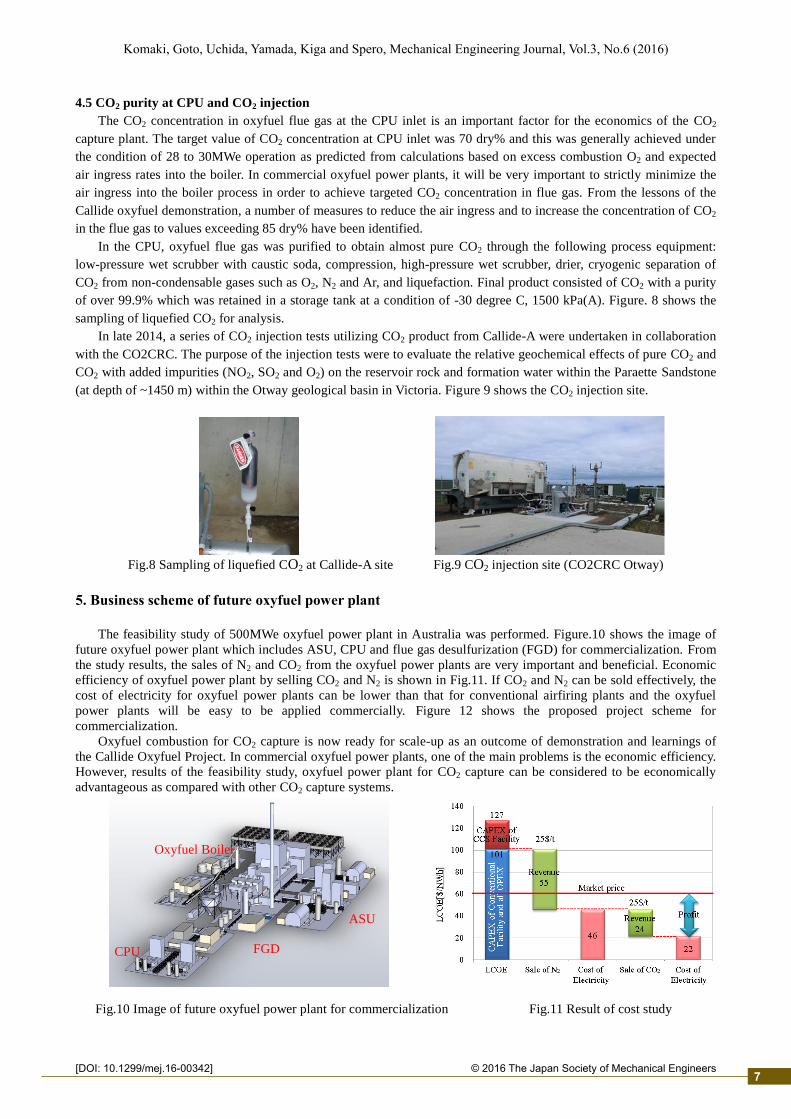
4.5 CO2 purity at CPU and CO2 injection
The CO2 concentration in oxyfuel flue gas at the CPU inlet is an important factor for the economics of the CO2
capture plant. The target value of CO2 concentration at CPU inlet was 70 dry% and this was generally achieved under
the condition of 28 to 30MWe operation as predicted from calculations based on excess combustion O2 and expected
air ingress rates into the boiler. In commercial oxyfuel power plants, it will be very important to strictly minimize the
air ingress into the boiler process in order to achieve targeted CO2 concentration in flue gas. From the lessons of the
Callide oxyfuel demonstration, a number of measures to reduce the air ingress and to increase the concentration of CO2
in the flue gas to values exceeding 85 dry% have been identified.
In the CPU, oxyfuel flue gas was purified to obtain almost pure CO2 through the following process equipment:
low-pressure wet scrubber with caustic soda, compression, high-pressure wet scrubber, drier, cryogenic separation of
CO2 from non-condensable gases such as O2, N2 and Ar, and liquefaction. Final product consisted of CO2 with a purity
of over 99.9% which was retained in a storage tank at a condition of -30 degree C, 1500 kPa(A). Figure. 8 shows the
sampling of liquefied CO2 for analysis.
In late 2014, a series of CO2 injection tests utilizing CO2 product from Callide-A were undertaken in collaboration
with the CO2CRC. The purpose of the injection tests were to evaluate the relative geochemical effects of pure CO2 and
CO2 with added impurities (NO2, SO2 and O2) on the reservoir rock and formation water within the Paraette Sandstone
(at depth of ~1450 m) within the Otway geological basin in Victoria. Figure 9 shows the CO2 injection site.
Fig.8 Sampling of liquefied CO2 at Callide-A site Fig.9 CO2 injection site (CO2CRC Otway)
The feasibility study of 500MWe oxyfuel power plant in Australia was performed. Figure.10 shows the image of
future oxyfuel power plant which includes ASU, CPU and flue gas desulfurization (FGD) for commercialization. From
the study results, the sales of N2 and CO2 from the oxyfuel power plants are very important and beneficial. Economic
efficiency of oxyfuel power plant by selling CO2 and N2 is shown in Fig.11. If CO2 and N2 can be sold effectively, the
cost of electricity for oxyfuel power plants can be lower than that for conventional airfiring plants and the oxyfuel
power plants will be easy to be applied commercially. Figure 12 shows the proposed project scheme for
commercialization.
Oxyfuel combustion for CO2 capture is now ready for scale-up as an outcome of demonstration and learnings of
the Callide Oxyfuel Project. In commercial oxyfuel power plants, one of the main problems is the economic efficiency.
However, results of the feasibility study, oxyfuel power plant for CO2 capture can be considered to be economically
advantageous as compared with other CO2 capture systems.
Fig.10 Image of future oxyfuel power plant for commercialization Fig.11 Result of cost study
Oxyfuel Boiler
FGD ASU
Turbine
Dry cooling
CPU
Oxyfuel Boiler
FGD CPU
ASU
7
5. Business scheme of future oxyfuel power plant

2
Komaki, Goto, Uchida, Yamada, Kiga and Spero, Mechanical Engineering Journal, Vol.3, No.6 (2016)
© 2016 The Japan Society of Mechanical Engineers[DOI: 10.1299/mej.16-00342]
Fig.12 Proposed project scheme
This report introduced the Callide Oxyfuel Project and operational results of the oxyfuel boiler after demonstration.
The data which was accumulated through the many tests will be used towards the commercialization of this technology.
To realize this oxyfiring system as a highly-efficient CCS system, we will push forward research and development
further. Recently, CO2 emissions (kg/MWh) from coal fired power plants are restricted less than or equivalent to NGCC
(Natural Gas Combined Cycle) level, for example 420 kg/MWh in Canada. To comply with regulation, the oxyfuel
power plant with CCUS (Carbon Capture, Utilization and Storage) can be expected.
Acknowledgments
These studies have been greatly supported by the Australian and Japanese Governments, the Queensland State
Government, NEDO (New Energy and Industrial Technology Development Organization), as well as by ACALET
(Australian Coal Association Low Emission Technology), Glencore, Schlumberger, CO2CRC, J-POWER, Mitsui &
CO., LTD., JCOAL (Japan Coal Energy Center) and many others in Australia and Japan, to which the authors would
like to express gratitude for their help and support.
References
International Energy Agency (IEA), World Energy Outlook 2014 (2014), pp.171-237
Komaki, A., Yamada, T., Kiga, T. and Spero, C., Initial Operation Results of the Oxyfuel Boiler in Demonstration
Project, International Conference on Power Engineering (ICOPE-13) (2013), Paper No.203
Okazaki, K. and Ando, T., NOx reduction mechanism in coal combustion with recycled CO2, Energy vol.22, No 2/3
(1997) pp.207-215
Yamada, T., Ishii, T., Takafuji, M. and Iso, Y., Study Results in Demonstration Operation of Oxyfuel Combustion boiler
for CO2 Capture, IHI Engineering Review vol.43 No.2 (2010), pp.47~54
Yamada, T., Tamura, M., Fujimori, T., Misawa, N., Kiga, T. and Spero, C., Test Results of Oxy-fuel Combustion and
Outline of Demonstration Project in Australia , International Conference on Power Engineering (ICOPE-07)
(2007), Paper No.29
8
6. Conclusion