Embed Size (px)
Citation preview
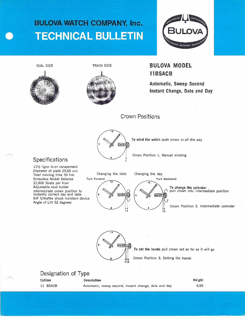
DIAL SIDE TRAIN SIDE BULOVA MODELllBSACBAutomatic, Sweep SecondInstant Change, Date and Day
Crown Positions
12
Specifications
To wind the watch push crown in all the way
Crown Position 1. Manual winding
111/2 ligne lever escapementDiameter of plate 25.60 mmTotal running time 50 hrs.Screwless Nickel Balance21,600 Beats per hourAdjustable stud holderIntermediate crown position toinstantly correct day and dateKIF Ultraflex shock resistant deviceAngle of Lift 52 degrees
Changing the date Changing the dayTurn Forward Turn Backward
12
To change the calendarpull crown into intermediate position
Crown Position 2. Intermediate calendar1 2 12
To set the hands puII crown out as far as it wi II go
Crown Position 3. Setting the hands
Designation of TypeCaliber
11 BSACB
Description
Automatic, sweep second, instant change, date and day
Height
5.95
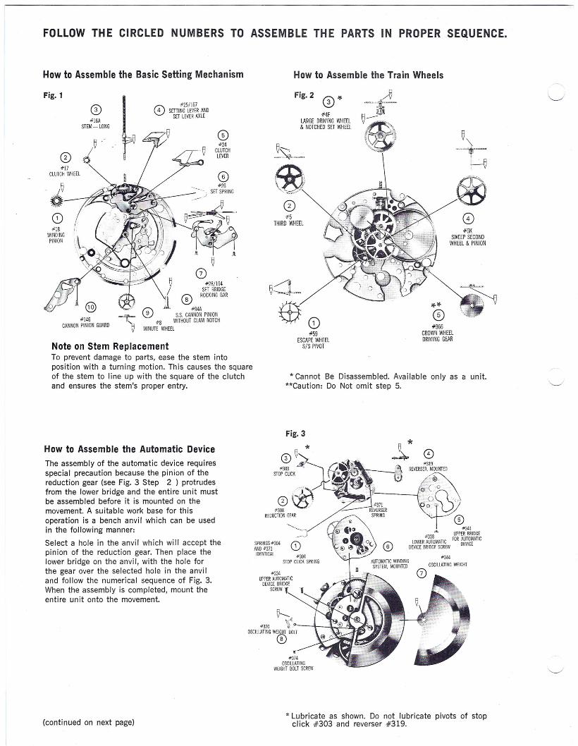
FOLLOW THE CIRCLED NUMBERS TO ASSEMBLE THE PARTS IN PROPER SEQUENCE.
How to Assemble the Basic Setting Mechanism
Fig. 1#25/1678 SmlNG LEVER AND
SET LEVERAXLECD#16A
STEM-LONG
o0)#24
CLUTCHLEVER
#17CLUTCH WHEEL CD
#26SET SPRINGi~_-----7f.~~o .,~~~
(3)#18
WINDINGPINION
$!J:::::;.q:
.O~· @#146
CANNON PINION GUARD
CD~ #28/164
/ RWKI~~ID~lR
'fn\9 :l. CD#94A~ \V S.S. CANNON PINION
- 0"c #8 WITHOUT CLAM NOTCHV MINUTE WHEEL
Note on Stem ReplacementTo prevent damage to parts, ease the stem intoposition with a turning motion. This causes the squareof the stem to line up with the square of the clutchand ensures the stem's proper entry.
How to Assemble the Automatic DeviceThe assembly of the automatic device requiresspecial precaution because the pinion of thereduction gear (see Fig. 3 Step 2) protrudesfrom the lower bridge and the entire unit mustbe assembled before it is mounted on themovement. A suitable work base for thisoperation is a bench anvil which can be usedin the following manner:
Select a hole in the anvil which will accept thepinion of the reduction gear. Then place thelower bridge on the anvil, with the hole forthe gear over the selected hole in the anviland follow the numerical sequence of Fig. 3.When the assembly is completed, mount theentire unit onto the movement.
(continued on next page)
How to Assemble the Train Wheels
Fig.2 CD ¥
#4FLARGE DRIVING WHEEL& NOTCHED SET WHEEL
~"--....~ .
Fb)\"~......•.,..-
o#5
THIRD WHEEL o#6K
SWEEP SECDNDWHEEL & PINION
~.'"~): ....~
#59ESCAPE WHEEL
S/S PIVOT
**CD#366
CROWN WHEELDRIVING GEAR
."~;
* Cannot Be Disassembled. Available only as a unit.**Caution: Do Not omit step 5.
Fig. 3
* o#319
REVERSER. MOUNTED
0~~O .~n\e
CD••. #341
#338 UPPER BRIDGELOWER AUTOMATIC FOR AUTOMATIC
DEVCE BRIDGE SCREW DEVICE
"303STOP CLICK
SPRINGS #304AND #371
IDENTICAL
~ ~JCD
#304STOP ClICK SPRING
#334UPPER AUTOMATIC
DEVICE BRIDGESCREW I
!5---.~#320 'j o_-'~--T.f'--~.A
OSCILLATING WEIGHT BOLT
®..,.
#374OSCILLATING
WEIGHT BOLT SCREW
* Lubricate as shown. Do not lubricate pivots of stopclick #303 and reverser #319.
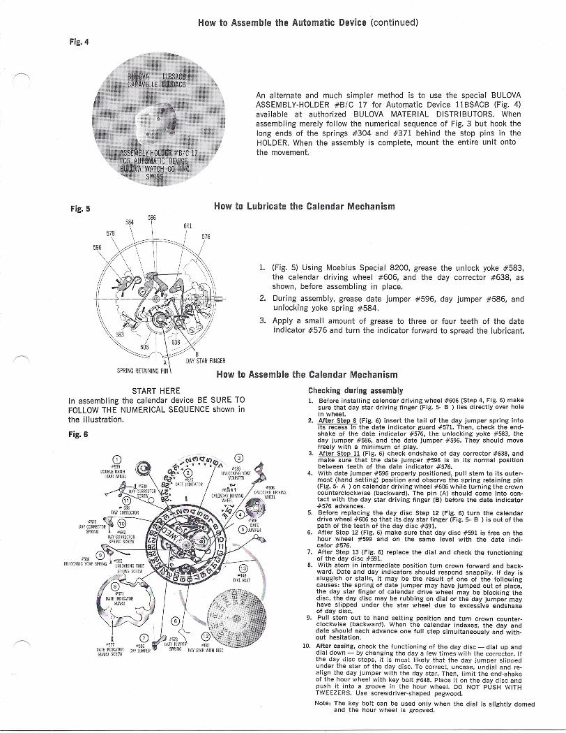
Fig. 4
How to Assemble the Automatic Device (continued)
An alternate and much simpler method is to use the special BULOVAASSEMBLY-HOLDER #B/C 17 for Automatic Device llBSACB (Fig. 4)available at authorized BULOVA MATERIAL DISTRIBUTORS. Whenassembling merely follow the numerical sequence of Fig. 3 but hook thelong ends of the springs #304 and #371 behind the stop pins in theHOLDER. When the assembly is complete, mount the entire unit ontothe movement.
Fig. 5 How to Lubricate the Calendar Mechanism
1. (Fig. 5) Using Moebius Special 8200, grease the unlock yoke #583,the calendar driving wheel #606, and the day corrector #638, asshown, before assembling in place.
2. During assembly, grease date jumper #596, day jumper #586, andunlocking yoke spring #584.
3. Apply a small amount of grease to three or four teeth of the dateindicator #576 and turn the indicator forward to spread the lubricant.
How to Assemble the Calendar MechanismSTART HERE
In assembling the calendar device BE SURE TOFOLLOW THE NUMERICAL SEQUENCE shown inthe illustration.
Fig. 6
1~577
DATE INDICATDRGUARD SCREW
Checking during assembly1. Before installing calendar driving wheel #606 (Step 4, Fig. 6) make
sure that day star driving finger (Fig. 5- B ) lies directly over holein wheel.
2. After Step 8 (Fig. 6) insert the tail of the day jumper spring intoits recess in the date indicator guard #571. Then, check the end-shake of the date indicator #576, the unlocking yoke #583, theday jumper #586, and the date jumper #596. They should movefreely with a minimum of play.
3. After Step 11 (Fig. 6) check endshake of day corrector #638, andmake sure that the date jumper #596 is in its normal positionbetween teeth of the date indicator #576.
4. With date jumper #596 properly positioned, pull stem to its outer-most Chand setting) position and observe the spring retaining pin(Fig. 5- A ) on calendar driving wheel #606 while turning the crowncounterclockwise (backward). The pin (A) should come into con-tact with the day star driving finger (B) before the date indicator#576 advances.
5. Before replacing the day disc Step 12 (Fig. 6) turn the calendardrive wheel #606 so that its day star finger (Fig. 5-. B ) is out of thepath of the teeth of the day disc #591.
6. After Step 12 (Fig. 6) make sure that day disc #591 is free on thehour wheel #599 and on the same level with the date indi-cator #576.
7. After Step 13 (Fig. 6) replace the dial and check the functioningof the day disc #591.
8. With stem in intermediate position turn crown forward and back-ward. Date and day indicators should respond snappily. If day issluggish or stalls, it may be the result of one of the followingcauses: the spring of date jumper may have jumped out of place,the day star finger of calendar drive wheel may be blocking thedisc, the day disc may be rubbing on dial or the day jumper mayhave slipped under the star wheel due to excessive endshakeof day disc.
9. Pull stem out to hand setting position and turn crown counter-clockwise (backward). When the calendar indexes, the day anddate should each advance one full step simultaneously and with-out hesitation.
10. After casing, check the functioning of the day disc - dial up anddial down - by changing the day a few times with the corrector. Ifthe day disc stops, it is most likely that the day jumper slippedunder the star of the day disc. To correct, uncase, undial and re-align the day jumper with the day star. Then, limit the end-shakeof the hour wheel with key bolt #648. Place it on the day disc andpush it into a groove in the hour wheel. DO NOT PUSH WITHTWEEZERS. Use screwdriver-shaped pegwood.
Note: The key bolt can be used only when the dial is slightly domedand the hour wheel is grooved.
Part No.
IS4F56K81314151617182425/1672628/164313235G37C37E3839404142444547
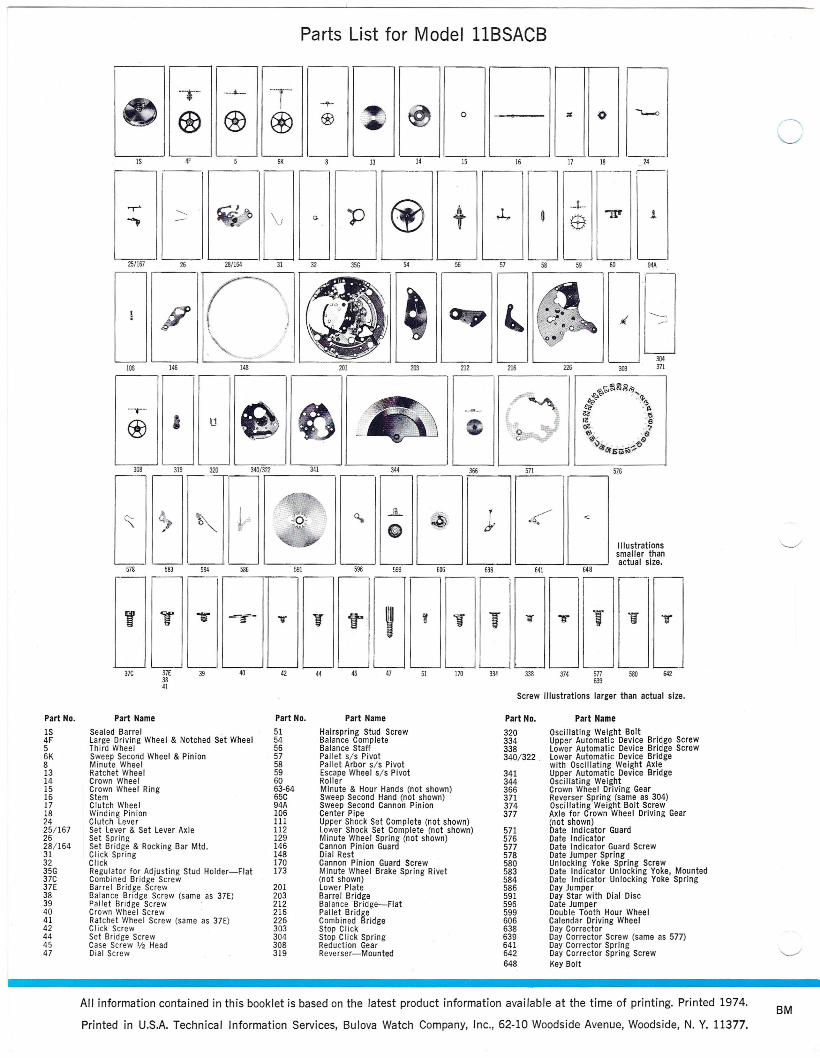
Parts List for Model IlBSACB
6K
31
o
14 15 16 24r---
4F 13
32 54 56 57
17 18---- r--- - r--- - r-----
.,.. ~ p @ t .l,. -1-<, \; ~ :$ "W~ - Q.~
~ '---=- ~~~
P (J l106 146 148 212 216 226----
3SG
IS
251167 26 281164
1
94A
---r-- e® I U
308 319 320 3401322 341 344 366I
~ <.t, -, 0.. .JiL~1;- ~ e.- e
578 583 584 586 591 596 599 606 638
•• T 1r ~- y T f"- , , V
~.
" '"
37C 37E 39 42 44 45 47 51 170 3343841
Part No.
5154565758596063-6465C94A106111112129146148170173
201203212216226303304308319
Part Name
Hairspring Stud ScrewBalance CompleteBalance StaffPallet s/s PivotPallet Arbor s/s PivotEscape Wheel s/s PivotRollerMinute & Hour Hands (not shown)Sweep Second Hand (not shown)Sweep Second Cannon PinionCenter PipeUpper Shock Set Complete (not shown)Lower Shock Set Complete (not shown)Minute Wheel Spring (not shown)Cannon Pinion GuardDial RestCannon Pinion Guard ScrewMinute Wheel Brake Spring Rivet(not shown)Lower PlateBarrel BridgeBalance Bridge-FlatPallet BridgeCombined BridgeStop ClickStop Click SpringReduction GearReverser-Mounted
Part No.
320334338340/322 _
341344366371374377
571576577578580583584586591596599606638639641642648
30437I
Part NameSealed Barrel _Large Driving Wheel & Notched Set Wheellhird WheelSweep Second Wheel & PinionMinute WheelRatchet WheelCrown WheelCrown Wheel RingStemClutch WheelWinding PinionClutch LeverSet Lever & Set Lever AxleSet SpringSet Bridge & Rocking Bar Mtd.Click SpringClickRegulator for Adjusting Stud Holder-FlatCombined Bridge ScrewBarrel Bridge ScrewBalance Bridge Screw (same as 37E)Pallet Bridge ScrewCrown Wheel ScrewRatchet Wheel Screw (same as 37E)Click ScrewSet Bridge ScrewCase Screw '/2 HeadDial Screw
303
,-'5;:..:71'-- __ , r---, 516
Illustrationssmaller thanactual size.
641 648
T11"
642577639
Screw illustrations larger than actual size.
338 374 580
Part Name
Oscillating Weight BoltUpper Automatic Device Bridge ScrewLower Automatic Device Bridge ScrewLower Automatic Device Bridgewith Oscillating Weight AxleUpper Automatic Device BridgeOscillating WeightCrown Wheel Driving GearReverser Spring (same as 304)Oscillating Weight Bolt ScrewAxle for Crown Wheel Driving Gear(not shown)Date Ind icator GuardDate IndicatorDate Indicator Guard ScrewDate Jumper SpringUnlocking Yoke Spring ScrewDate Indicator Unlocking Yoke, MountedDate Indicator Unlocking Yoke SpringDay JumperDay Star with Dial DiscDate JumperDouble Tooth Hour WheelCalendar Driving WheelDay CorrectorDay Corrector Screw (same as 577)Day Corrector SpringDay Corrector Spring ScrewKey Bolt
BMAll information contained in this booklet is based on the latest product information available at the time of printing. Printed 1974.
Printed in U.S.A. Technical Information Services, Bulova Watch Company, Inc., 62-10 Woodside Avenue, Woodside, N. Y_ 11377_