Embed Size (px)
Citation preview
Bunkering, infrastructure, storage, and processing of LNG Emissions rEduction to comply with future environmental regulations, improvements of ships’ emissions are urgently required. LnG as a ship’s fuel will reduce nox to clearly below tier iii level, sox and particulate matters to about zero and co2 by 20 to 30% without any treatment of combustion gases. main challenges of the usage of LnG, however, include the safe storage and processing of the liquefied gas as well as the bunker infrastructure, procedure and equipment.
Jürgen Harperscheidt
Using LNG as fuel has been a common technology for decades on LNG carriers. The safety record for loading/unloading of such vessels as well as for the operation of propulsion systems based on burning boil-off gas is very good. During the last 10 years, operational experience has been gained in Norway where small ships have been equipped with LNG propulsion, e. g. ferries and offshore supply vessels.The difficulty when providing LNG as fuel to a wider scale of ships and shipping ar-eas is the bunker infrastructure to make LNG available wherever ship’s operators may need it. It is therefore crucial for the introduction of LNG as a fuel to have an infrastructure in place that secures safe, fast and reliable accessibility to LNG for the operators - a major task for those involved in small scale LNG.
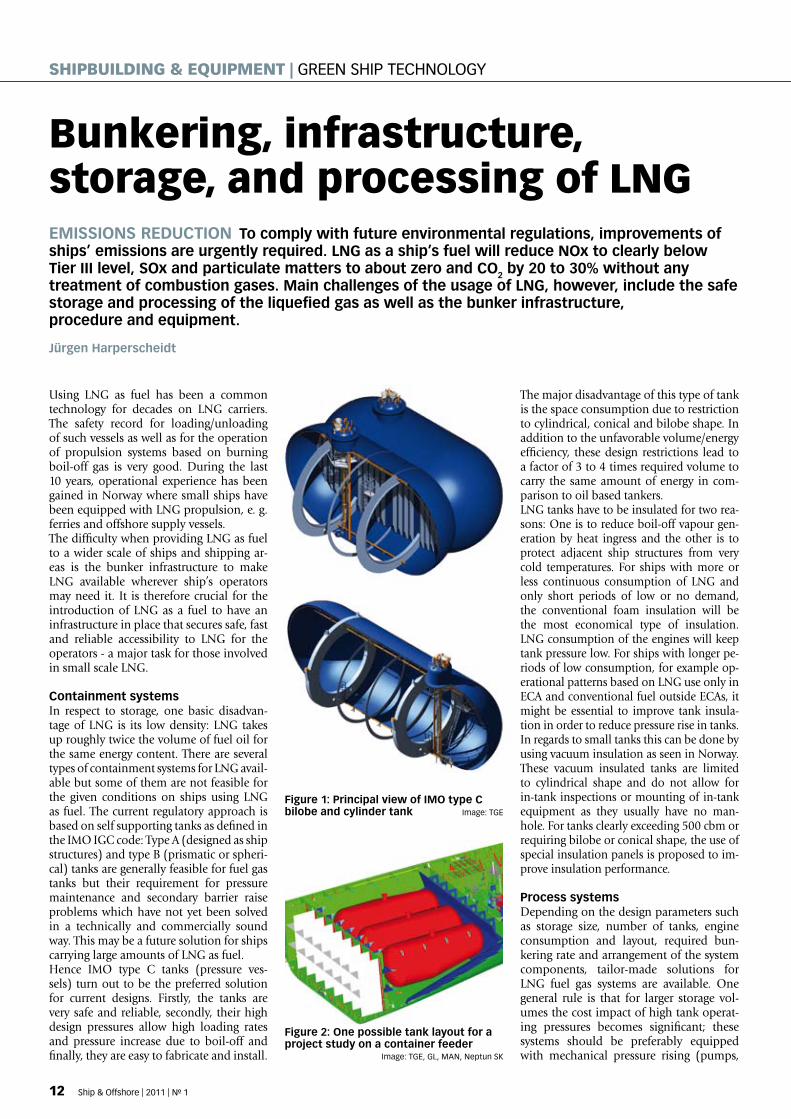
containment systemsIn respect to storage, one basic disadvan-tage of LNG is its low density: LNG takes up roughly twice the volume of fuel oil for the same energy content. There are several types of containment systems for LNG avail-able but some of them are not feasible for the given conditions on ships using LNG as fuel. The current regulatory approach is based on self supporting tanks as defined in the IMO IGC code: Type A (designed as ship structures) and type B (prismatic or spheri-cal) tanks are generally feasible for fuel gas tanks but their requirement for pressure maintenance and secondary barrier raise problems which have not yet been solved in a technically and commercially sound way. This may be a future solution for ships carrying large amounts of LNG as fuel. Hence IMO type C tanks (pressure ves-sels) turn out to be the preferred solution for current designs. Firstly, the tanks are very safe and reliable, secondly, their high design pressures allow high loading rates and pressure increase due to boil-off and finally, they are easy to fabricate and install.
The major disadvantage of this type of tank is the space consumption due to restriction to cylindrical, conical and bilobe shape. In addition to the unfavorable volume/energy efficiency, these design restrictions lead to a factor of 3 to 4 times required volume to carry the same amount of energy in com-parison to oil based tankers. LNG tanks have to be insulated for two rea-sons: One is to reduce boil-off vapour gen-eration by heat ingress and the other is to protect adjacent ship structures from very cold temperatures. For ships with more or less continuous consumption of LNG and only short periods of low or no demand, the conventional foam insulation will be the most economical type of insulation. LNG consumption of the engines will keep tank pressure low. For ships with longer pe-riods of low consumption, for example op-erational patterns based on LNG use only in ECA and conventional fuel outside ECAs, it might be essential to improve tank insula-tion in order to reduce pressure rise in tanks. In regards to small tanks this can be done by using vacuum insulation as seen in Norway. These vacuum insulated tanks are limited to cylindrical shape and do not allow for in-tank inspections or mounting of in-tank equipment as they usually have no man-hole. For tanks clearly exceeding 500 cbm or requiring bilobe or conical shape, the use of special insulation panels is proposed to im-prove insulation performance.
Process systemsDepending on the design parameters such as storage size, number of tanks, engine consumption and layout, required bun-kering rate and arrangement of the system components, tailor-made solutions for LNG fuel gas systems are available. One general rule is that for larger storage vol-umes the cost impact of high tank operat-ing pressures becomes significant; these systems should be preferably equipped with mechanical pressure rising (pumps,
Figure 1: Principal view of imo type c bilobe and cylinder tank Image: TGE
Figure 2: one possible tank layout for a project study on a container feeder Image: TGE, GL, MAN, Neptun SK
12 Ship & Offshore | 2011 | No 1
ShipBuiLdiNG & EquipmENt | GrEEN ShIp TEchNOLOGy
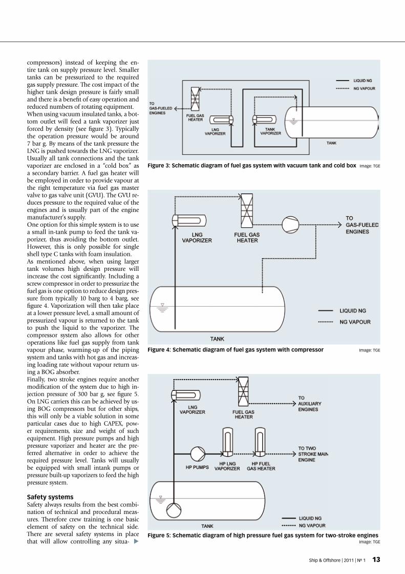
Figure 4: schematic diagram of fuel gas system with compressor Image: TGE
Figure 3: schematic diagram of fuel gas system with vacuum tank and cold box Image: TGE
Figure 5: schematic diagram of high pressure fuel gas system for two-stroke engines Image: TGE
compressors) instead of keeping the en-tire tank on supply pressure level. Smaller tanks can be pressurized to the required gas supply pressure. The cost impact of the higher tank design pressure is fairly small and there is a benefit of easy operation and reduced numbers of rotating equipment.When using vacuum insulated tanks, a bot-tom outlet will feed a tank vaporizer just forced by density (see figure 3). Typically the operation pressure would be around 7 bar g. By means of the tank pressure the LNG is pushed towards the LNG vaporizer. Usually all tank connections and the tank vaporizer are enclosed in a “cold box” as a secondary barrier. A fuel gas heater will be employed in order to provide vapour at the right temperature via fuel gas master valve to gas valve unit (GVU). The GVU re-duces pressure to the required value of the engines and is usually part of the engine manufacturer’s supply.One option for this simple system is to use a small in-tank pump to feed the tank va-porizer, thus avoiding the bottom outlet. However, this is only possible for single shell type C tanks with foam insulation.As mentioned above, when using larger tank volumes high design pressure will increase the cost significantly. Including a screw compressor in order to pressurize the fuel gas is one option to reduce design pres-sure from typically 10 barg to 4 barg, see figure 4. Vaporization will then take place at a lower pressure level, a small amount of pressurized vapour is returned to the tank to push the liquid to the vaporizer. The compressor system also allows for other operations like fuel gas supply from tank vapour phase, warming-up of the piping system and tanks with hot gas and increas-ing loading rate without vapour return us-ing a BOG absorber.Finally, two stroke engines require another modification of the system due to high in-jection pressure of 300 bar g, see figure 5. On LNG carriers this can be achieved by us-ing BOG compressors but for other ships, this will only be a viable solution in some particular cases due to high CAPEX, pow-er requirements, size and weight of such equipment. High pressure pumps and high pressure vaporizer and heater are the pre-ferred alternative in order to achieve the required pressure level. Tanks will usually be equipped with small intank pumps or pressure built-up vaporizers to feed the high pressure system.
safety systemsSafety always results from the best combi-nation of technical and procedural meas-ures. Therefore crew training is one basic element of safety on the technical side. There are several safety systems in place that will allow controlling any situa-
Ship & Offshore | 2011 | No 1 13
tion that might occur during system opera-tion. IMO interim guideline MSC 285(86) as a preliminary version of IGF-Code and the Rules for LNG fuelled ships that have been published by all major classification societies, have been derived from chapter 16 of IGC-Code for using cargo as fuel, try-ing to adapt the solutions to the different purpose in case of ships that are not gas carriers. Decade-long experience with LNG operations indicates the main measures to follow to ensure safe handling of LNG. One of these safety measures is a gas de-tection system which can detect even small amounts of gas escaping from the closed system. The relevant parts of the fuel gas plant will be shut down as soon as gas is detected. Areas where leakages may occur are equipped with ex-proof equipment, so even if the atmosphere contains an ex-plosive mixture of gas and Oxygen, there will be no spark to ignite it. Gas piping
and LNG piping will be double walled or located inside a ventilated duct in order to have a secondary barrier in place in case of any leakages. Spill detection and stainless steel drip trays are located wherever LNG might escape and harm the ship structures by cold brittleness. Piping sections not in use are inerted with Nitrogen, e. g. bunker-ing line after bunkering is finished.
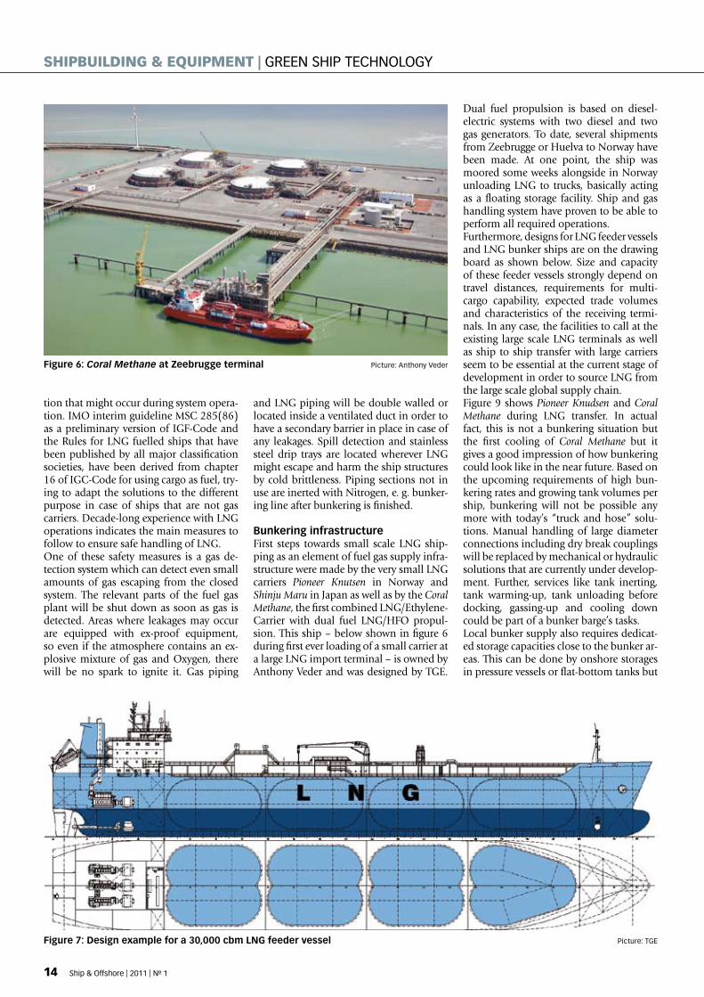
Bunkering infrastructureFirst steps towards small scale LNG ship-ping as an element of fuel gas supply infra-structure were made by the very small LNG carriers Pioneer Knutsen in Norway and Shinju Maru in Japan as well as by the Coral Methane, the first combined LNG/Ethylene-Carrier with dual fuel LNG/HFO propul-sion. This ship – below shown in figure 6 during first ever loading of a small carrier at a large LNG import terminal – is owned by Anthony Veder and was designed by TGE.
Dual fuel propulsion is based on diesel-electric systems with two diesel and two gas generators. To date, several shipments from Zeebrugge or Huelva to Norway have been made. At one point, the ship was moored some weeks alongside in Norway unloading LNG to trucks, basically acting as a floating storage facility. Ship and gas handling system have proven to be able to perform all required operations.Furthermore, designs for LNG feeder vessels and LNG bunker ships are on the drawing board as shown below. Size and capacity of these feeder vessels strongly depend on travel distances, requirements for multi-cargo capability, expected trade volumes and characteristics of the receiving termi-nals. In any case, the facilities to call at the existing large scale LNG terminals as well as ship to ship transfer with large carriers seem to be essential at the current stage of development in order to source LNG from the large scale global supply chain.Figure 9 shows Pioneer Knudsen and Coral Methane during LNG transfer. In actual fact, this is not a bunkering situation but the first cooling of Coral Methane but it gives a good impression of how bunkering could look like in the near future. Based on the upcoming requirements of high bun-kering rates and growing tank volumes per ship, bunkering will not be possible any more with today’s “truck and hose” solu-tions. Manual handling of large diameter connections including dry break couplings will be replaced by mechanical or hydraulic solutions that are currently under develop-ment. Further, services like tank inerting, tank warming-up, tank unloading before docking, gassing-up and cooling down could be part of a bunker barge’s tasks.Local bunker supply also requires dedicat-ed storage capacities close to the bunker ar-eas. This can be done by onshore storages in pressure vessels or flat-bottom tanks but
Figure 6: Coral Methane at Zeebrugge terminal picture: Anthony Veder
Figure 7: design example for a 30,000 cbm LnG feeder vessel picture: TGE
14 Ship & Offshore | 2011 | No 1
ShipBuiLdiNG & EquipmENt | GrEEN ShIp TEchNOLOGy
also by floating storages. One alternative solution with barges that would be carried like very large containers by a barge carrier is under evaluation, see figure 10. Summing up the mentioned requirements on the bunkering infrastructure, we can see a demand for significant investment that may possibly not be supported by bun-kering activities only. Sharing the bunker supply chain with local consumers such as industries or power plants would create an appealing portfolio for investments into this new infrastructure.
conclusionTechnical solutions for the safe operation of LNG fuel gas from the source (large termi-nal) down to the consumer (main engine of the LNG-fuelled ships) are currently avail-
able. Emission control and rather low LNG prices should be the main drivers to build the required infrastructure. Small scale LNG shipping has already begun and with the relevant dates for emission legislation ap-proaching, the pressure rises for everybody to find a solution to meet the upcoming challenges. LNG as a ship’s fuel is only one possible solution but it should play a ma-jor role due to the advantages compared to other solutions. TGE is confident that, over the course of the next years, an increasing number of ships will be equipped and sail-ing with LNG propulsion.
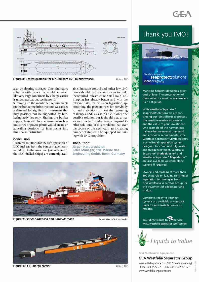
Figure 8: design example for a 2,000 cbm LnG bunker vessel picture: TGE
the author:Jürgen Harperscheidt, sales manager, tGE marine Gas Engineering GmbH, Bonn, Germany
Figure 9: Pioneer Knudsen and Coral Methane picture: Gasnor/Anthony Veder
Figure 10: LnG barge carrier picture: TGE
Maritime habitats demand a great deal of love. The preservation of clean water for sensitive sea dwellers is an obligation.
With Westfalia Separator® seaprotectsolutions we are con-tinuing our joint efforts to protect the sensitive marine ecosystem and the value of your investment. One example of the harmonious balance between environmental and economic requirements is theWestfalia Separator® CombiMaster®, a centrifugal separation system designed for combined bilgewater and sludge treatment. Westfalia Separator® SludgeMaster® and Westfalia Separator® BilgeMaster® are also available as stand-alone systems if required.
Owners and captains of more than 500 ships rely on leading centrifugal separation technologies fromGEA Westfalia Separator Group for the treatment of bilgewater and sludge.
Complete, ready-to-connect systems are available as compact units for new installation or as retrofit.
Your direct route to service: www.westfalia-separator.com / service
Thank you IMO!
MA
-4-1
0-01
1
GEA Mechanical Equipment
GEA Westfalia Separator GroupWerner-Habig-Straße 1 · 59302 Oelde (Germany)Phone +49 2522 77-0 · Fax +49 2522 77-1778www.westfalia-separator.com
Liquids to Value
DVV Media Group GmbH Sales Department P.O. BOX 10 16 09 20010 Hamburg GERMANY
Yes, I would like to test 3 issues Ship&Offshore Ship&Offshore is the English-language international trade magazine which provides you six times a year with global insights into trends and developments of the maritime industry. Ship&Offshore offers the reader specialist information from all sectors of the maritime industry, focusing on the shipbuilding industry, ship technology and the growth market, offshore technology.
---> If you prefer to fill in your data online, please click here. <--- Please send the trial issues of Ship&Offshore to:
by eMail or by post
Company Company activity Department First name/Name Telephone / Fax eMail Street / P.O. BOX Postal code, Town, Country Date / Signature SPI_ON_1102
[email protected] www.shipandoffshore.net
Shipbuilding & Equipment
16
Shipbuilding & Equipment
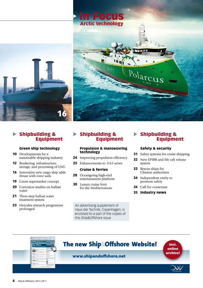
Arctic technology
Shipbuilding & Equipment
Green ship technology
10 Developments for a sustainable shipping industry
12 Bunkering, infrastructure, storage, and processing of LNG
16 Innovative new cargo ship adds thrust with rotor sails
19 Green supertanker concept
20 Corrosion studies on ballast water
21 Three-step ballast water treatment system
23 Hercules research programme prolonged
An advertising supplement of Haus der Technik, Copenhagen, is enclosed to a part of the copies of this Ship&Offshore issue
Propulsion & manoeuvring technology
24 Improving propulsion efficiency
25 Enhancements to 1163 series
Cruise & ferries
28 Oceangoing high-end entertainment platform
30 Luxury cruise ferry for the Mediterranean
Safety & security
31 Safety systems for cruise shipping
32 New EPIRB and life raft release system
33 Rescue ships for Chinese authorities
34 Independent entity to promote safety
34 Call for consensus
35 Industry news
In Focus
The new Website!
www.shipandoff shore.net
incl. online
archive!
3434_anz_mtp_spi_homepage_183x40.indd 1 01.02.2011 15:20:264 Ship & Offshore | 2011 | No 1 Ship & Offshore | 2011 | No 1 5
5738
Navigation & communication
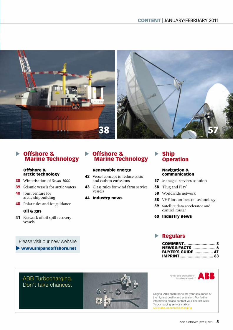
57 Managed-services solution
58 ‘Plug and Play’
58 Worldwide network
58 VHF locator beacon technology
59 Satellite data accelerator and control router
60 Industry news
Offshore & Marine Technology
Offshore & Marine Technology
COMMENT ........................... 3NEwS & FACTS ................... 6BuyEr‘S GuIdE ................ 47IMPrINT ............................. 63
Ship Operation
regulars
renewable energy
42 Vessel concept to reduce costs and carbon emissions
43 Class rules for wind farm service vessels
44 Industry news
Offshore & arctic technology
38 Winterisation of Sevan 1000
39 Seismic vessels for arctic waters
40 Joint venture for arctic shipbuilding
40 Polar rules and ice guidance
Oil & gas
41 Network of oil spill recovery vessels
ABB Turbocharging.Don’t take chances.
Original ABB spare parts are your assurance ofthe highest quality and precision. For furtherinformation please contact your nearest ABBTurbocharging service station.www.abb.com/turbocharging
ABBTC_AD_SERV02_W185H40Strip_SH 17.09.09 18:25 Seite 1
Please visit our new website
www.shipandoffshore.net
4 Ship & Offshore | 2011 | No 1 Ship & Offshore | 2011 | No 1 5
CONTENT | JaNuaRy/febRuaRy 2011