Embed Size (px)
Citation preview
Development of a wide field spherical aberration corrector for the
Hobby Eberly Telescope
James H. Burge†, S. Benjamin, M. Dubin, A. Manuel, M. Novak, C. J. Oh, M. Valente, C. Zhao College of Optical Sciences, University of Arizona, Tucson, AZ 85721
J. A. Booth, J. M. Good, Gary J. Hill, H. Lee, P. J. MacQueen, M. Rafal, R. Savage, M. P. Smith, B. Vattiat
McDonald Observatory, University of Texas at Austin, 1 University Station C1402, Austin, TX 78712-0259, USA
ABSTRACT
A 4-mirror prime focus corrector is under development to provide seeing-limited images for the 10-m aperture Hobby-Eberly Telescope (HET) over a 22 arcminute wide field of view. The HET uses an 11-m fixed elevation segmented spherical primary mirror, with pointing and tracking performed by moving the prime focus instrument package (PFIP) such that it rotates about the virtual center of curvature of the spherical primary mirror. The images created by the spherical primary mirror are aberrated with 13 arcmin diameter point spread function. The University of Arizona is developing the 4-mirror wide field corrector to compensate the aberrations from the primary mirror and present seeing limited imaged to the pickoffs for the fiber-fed spectrographs. The requirements for this system pose several challenges, including optical fabrication of the aspheric mirrors, system alignment, and operational mechanical stability.
Keywords: Optical systems, telescope, astronomical optics, Hobby Eberly Telescope
1. INTRODUCTION The Hobby Eberly Telescope* is in the midst of a significant upgrade to enable an unprecedented spectroscopic survey. 1 As part of this, the University of Arizona is providing the 4-mirror Wide Field Corrector (WFC) which corrects the spherical and field aberrations from the primary mirror to provide sub-arcsecond images over a 22 arcmin diameter field. The top level requirements for the WFC are summarized in Table 1. Table 1. Key requirements for the HET Wide Field Corrector Parameter Requirement Field of view 22 arcminute diameter Image quality 80% EE 0.45 arcsec to 5 arcmin, 0.8 arcsec to 11 arcmin Optical throughput Relative to 10-m circular aperture, 0.80 on axis, > 0.64 at 11’ Effective focal length 36.5 ± 0.05 m (177 µm/arcsec) Image mapping stability Image position must be stable to 70 µm across field over all conditions Wavelength range 350 – 1800 nm Mass < 2000 kg Stiffness Lowest resonance > 20 Hz Interfaces Three-point semi-kinematic attachment Operational environment 35° elevation, ±8.5° in el, az
10°C ± 20° Enclosure Air-tight, light-tight, with steady positive pressure purge Alignment methodology Must provide method and tooling to removed and realign mirrors * The Hobby – Eberly Telescope is operated by McDonald Observatory on behalf of the University of Texas at Austin, Pennsylvania State University, Stanford University, Ludwig-Maximillians-Universität München, and Georg-August-Universität, Göttingen.
†J. H. Burge is Professor of Optical Sciences and Astronomy, University of Arizona. 520-621-8182, [email protected]
Ground-based and Airborne Telescopes III, edited by Larry M. Stepp, Roberto Gilmozzi, Helen J. HallProc. of SPIE Vol. 7733, 77331J · © 2010 SPIE · CCC code: 0277-786X/10/$18 · doi: 10.1117/12.857835
Proc. of SPIE Vol. 7733 77331J-1
Downloaded from SPIE Digital Library on 29 Sep 2011 to 128.196.206.125. Terms of Use: http://spiedl.org/terms
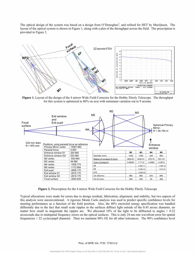
The optical design of the system was based on a design from O’Donoghue2, and refined for HET by MacQueen. The layout of the optical system is shown in Figure 1, along with a plot of the throughput across the field. The prescription is provided in Figure 2.
22 arcmin FOV
Figure 1. Layout of the design of the 4 mirror Wide Field Corrector for the Hobby Eberly Telescope. The throughput
for this system is optimized to 80% on axis with minimum variation out to 9 arcmin.
Exit window and Exit pupil Focal
surface
M5
M4
M2 M3
Entrance window
232 mm diam R = 970 mm
Spherical Primary Mirror: R = 26.164 m
Figure 2. Prescription for the 4 mirror Wide Field Corrector for the Hobby Eberly Telescope
Typical allocations were made for errors due to design residual, fabrication, alignment, and stability, but two aspects of this analysis were unconventional. A rigorous Monte Carlo analysis was used to predict specific confidence levels for meeting performance as a function of the field position. Also, the 80% encircled energy specification was handled differently due to the fact that small scale ripples in the surfaces diffract light outside of the 0.45 arcsec diameter, no matter how small in magnitude the ripples are. We allocated 10% of the light to be diffracted to angles > 0.22 arcseconds due to midspatial frequency errors on the optical surfaces. This is only 24 nm rms wavefront error for spatial frequencies > 22 cycles/pupil diameter. Then we maintain 90% EE for all other tolerances. The 90% confidence level
Positions, using paraxial focus as reference Primary Mirror vertex 13081.960 Paraxial focus 0.000 Entrance window S1 255.960 Entrance window S2r 253.960 M2 vertex -932.664 M3 vertex 49.985 M4 vertex -1509.774 M5 vertex -1172.664 Exit pupil -2606.170 Exit window S1 -2616.170 Exit window S2 -2619.170 Focal surface -3583.629
M2 M3 M4 M5 Diameter (mm) 1020 1020 248 900
Radius of curvature R (mm) 2620.81 2032.51 -376.70 742.121
Conic Constant K 0.66287 -7.7112 -2.0983 -0.2673
A6 - -8.26E-17 - -1.59E-19
A8 - 8.48E-23 - 1.81E-24
A10 - -3.59E-29 - -
CA OD(mm) 960 980 244 880
CA ID (mm) 326 325 30 260
Proc. of SPIE Vol. 7733 77331J-2
Downloaded from SPIE Digital Library on 29 Sep 2011 to 128.196.206.125. Terms of Use: http://spiedl.org/terms
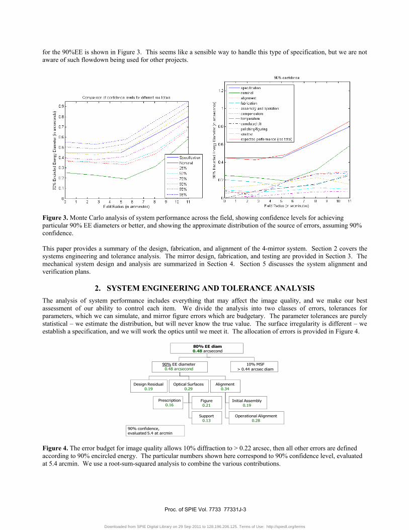
for the 90%EE is shown in Figure 3. This seems like a sensible way to handle this type of specification, but we are not aware of such flowdown being used for other projects.
Figure 3. Monte Carlo analysis of system performance across the field, showing confidence levels for achieving particular 90% EE diameters or better, and showing the approximate distribution of the source of errors, assuming 90% confidence.
This paper provides a summary of the design, fabrication, and alignment of the 4-mirror system. Section 2 covers the systems engineering and tolerance analysis. The mirror design, fabrication, and testing are provided in Section 3. The mechanical system design and analysis are summarized in Section 4. Section 5 discusses the system alignment and verification plans.
2. SYSTEM ENGINEERING AND TOLERANCE ANALYSIS The analysis of system performance includes everything that may affect the image quality, and we make our best assessment of our ability to control each item. We divide the analysis into two classes of errors, tolerances for parameters, which we can simulate, and mirror figure errors which are budgetary. The parameter tolerances are purely statistical – we estimate the distribution, but will never know the true value. The surface irregularity is different – we establish a specification, and we will work the optics until we meet it. The allocation of errors is provided in Figure 4.
Design Residual0.19
10% MSF > 0.44 arcsec diam
Optical Surfaces0.29
Alignment0.34
Operational Alignment0.28
Figure 0.21
Support0.13
Initial Assembly0.19
90% confidence,evaluated 5.4 at arcmin
80% EE diam0.48 arcsecond
90% EE diameter0.48 arcsecond
Prescription 0.16
Figure 4. The error budget for image quality allows 10% diffraction to > 0.22 arcsec, then all other errors are defined according to 90% encircled energy. The particular numbers shown here correspond to 90% confidence level, evaluated at 5.4 arcmin. We use a root-sum-squared analysis to combine the various contributions.
Proc. of SPIE Vol. 7733 77331J-3
Downloaded from SPIE Digital Library on 29 Sep 2011 to 128.196.206.125. Terms of Use: http://spiedl.org/terms
The error budget above was used for planning, but the performance estimate was based on Monte Carlo analysis. The results of this analysis are summarized above in Figure 3. The input parameters to this analysis are provided below. 2.1 Mirror prescription tolerances
Mirror fabrication tolerances in this section include the error in the knowledge of the radii and conic constants. All other errors (such as those in the higher order aspheric terms) are included in the polishing and figuring errors section. Table 2 lists the measurement tolerances used in the Monte Carlo simulation to estimate performance. The manufacturing tolerances are several times looser, since we can accommodate known offsets in these parameters by respacing.
Table 2. Manufacturing tolerances for M2, M3, M4 M5 and focal plane M2 M3 M4 M5 Focal Plane
ΔR uncertainty (mm) 0.075 0.075 0.045 0.04 3.44 Δk uncertainty 0.0011 0.0008 0.0006 0.0001 NA
2.2 Alignment and stability tolerances
Alignment tolerances include allowable uncertainty in relative position of the individual mirrors and groups of mirrors, as listed below in Table 3. The decenter and tilt tolerances are provided for each of the x and the y directions, so the net alignment tolerance is 1.4 x larger, at arbitrary angle. Tables 3 and 4 provide initial alignment tolerances and tolerances for operational changes, which are nominally ¼ of the initial alignment tolerances. All of the tilts in Tables 3 and 4 are given in mm displacement across the diameter. The diameters assumed are provided in Figure 2.
Table 3. Alignment tolerances in microns M2 to M3 axial 100M2 to M5 axial 100M4 to M5 axial 20M2 decenter (x or y) 50M3 decenter (x or y) 50M4 decenter (x or y) 20M4 M5 decenter (x or y) 50M2 tilt (x or y) 50M3 tilt (x or y) 50M4 tilt (x or y) 20M4 M5 tilt (x or y) 50Focal plane axial position 1000Focal plane tilt (x or y) 50M2-M5 together decenter (x or y) 250M2-M5 together tilt (x or y) 250
Table 4. Operational tolerances in microns M2 to M3 axial 25M2 to M5 axial 25M4 to M5 axial 5M2 decenter (x or y) 12.5M3 decenter (x or y) 12.5M4 decenter (x or y) 5M4 M5 decenter (x or y) 12.5M2 tilt (x or y) 12.5M3 tilt (x or y) 12.5M4 tilt (x or y) 5M4 M5 tilt (x or y) 12.5Focal plane axial position 250Focal plane tilt (x or y) 12.5M2-M5 together decenter (x or y) 62.5M2-M5 together tilt (x or y) 62.5
2.3 Compensator perturbations
In operation, the WFC system will be moved in all 6 degrees of freedom to define pointing and to minimize the aberrations of focus and coma. Our analysis included such compensation. However, the system can only be controlled with finite precision. The resolution for each of these degrees of freedom is ±15μm. For the system tilt, 15μm is across the 0.7 meter radius. A two-step analysis was required to model this correctly when we developed the Monte Carlo simulation. First all alignment and fabrication parameters were perturbed according to uniform statistical distribution defined by the tolerance values. Then this perturbed system position was optimized for pointing and image quality. An additional perturbation of the system position defined by the 15 µm resolution was performed. The effect of perturbing the compensators is mostly constant across the field because these degrees of freedom (like tilting or decentering a secondary mirror of a two mirror telescope) cause mostly constant coma throughout the field.
Proc. of SPIE Vol. 7733 77331J-4
Downloaded from SPIE Digital Library on 29 Sep 2011 to 128.196.206.125. Terms of Use: http://spiedl.org/terms
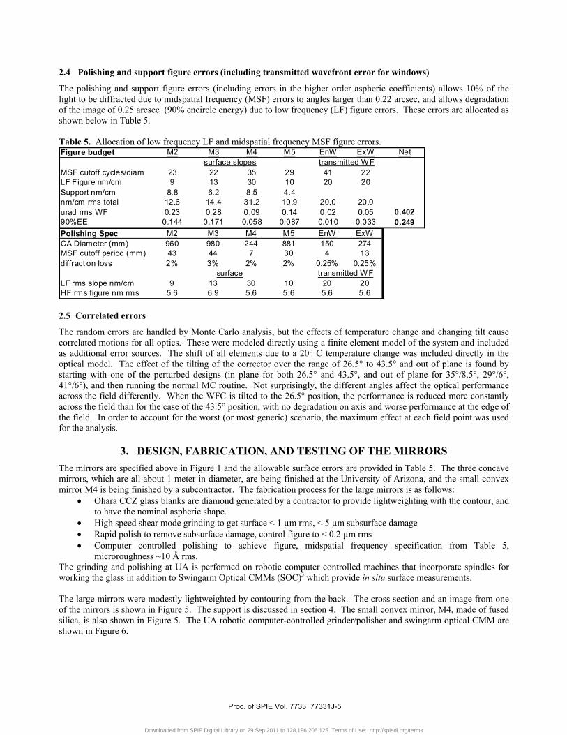
2.4 Polishing and support figure errors (including transmitted wavefront error for windows)
The polishing and support figure errors (including errors in the higher order aspheric coefficients) allows 10% of the light to be diffracted due to midspatial frequency (MSF) errors to angles larger than 0.22 arcsec, and allows degradation of the image of 0.25 arcsec (90% encircle energy) due to low frequency (LF) figure errors. These errors are allocated as shown below in Table 5. Table 5. Allocation of low frequency LF and midspatial frequency MSF figure errors.
2.5 Correlated errors
The random errors are handled by Monte Carlo analysis, but the effects of temperature change and changing tilt cause correlated motions for all optics. These were modeled directly using a finite element model of the system and included as additional error sources. The shift of all elements due to a 20° C temperature change was included directly in the optical model. The effect of the tilting of the corrector over the range of 26.5° to 43.5° and out of plane is found by starting with one of the perturbed designs (in plane for both 26.5° and 43.5°, and out of plane for 35°/8.5°, 29°/6°, 41°/6°), and then running the normal MC routine. Not surprisingly, the different angles affect the optical performance across the field differently. When the WFC is tilted to the 26.5° position, the performance is reduced more constantly across the field than for the case of the 43.5° position, with no degradation on axis and worse performance at the edge of the field. In order to account for the worst (or most generic) scenario, the maximum effect at each field point was used for the analysis.
3. DESIGN, FABRICATION, AND TESTING OF THE MIRRORS The mirrors are specified above in Figure 1 and the allowable surface errors are provided in Table 5. The three concave mirrors, which are all about 1 meter in diameter, are being finished at the University of Arizona, and the small convex mirror M4 is being finished by a subcontractor. The fabrication process for the large mirrors is as follows:
• Ohara CCZ glass blanks are diamond generated by a contractor to provide lightweighting with the contour, and to have the nominal aspheric shape.
• High speed shear mode grinding to get surface < 1 µm rms, < 5 µm subsurface damage • Rapid polish to remove subsurface damage, control figure to < 0.2 µm rms • Computer controlled polishing to achieve figure, midspatial frequency specification from Table 5,
microroughness ~10 Å rms. The grinding and polishing at UA is performed on robotic computer controlled machines that incorporate spindles for working the glass in addition to Swingarm Optical CMMs (SOC)3 which provide in situ surface measurements. The large mirrors were modestly lightweighted by contouring from the back. The cross section and an image from one of the mirrors is shown in Figure 5. The support is discussed in section 4. The small convex mirror, M4, made of fused silica, is also shown in Figure 5. The UA robotic computer-controlled grinder/polisher and swingarm optical CMM are shown in Figure 6.
Figure budget M2 M3 M4 M5 EnW ExW Net
MSF cutoff cycles/diam 23 22 35 29 41 22LF Figure nm/cm 9 13 30 10 20 20Support nm/cm 8.8 6.2 8.5 4.4nm/cm rms total 12.6 14.4 31.2 10.9 20.0 20.0urad rms WF 0.23 0.28 0.09 0.14 0.02 0.05 0.40290%EE 0.144 0.171 0.058 0.087 0.010 0.033 0.249
surface slopes transmitted WF
Polishing Spec M2 M3 M4 M5 EnW ExWCA Diameter (mm) 960 980 244 881 150 274MSF cutoff period (mm) 43 44 7 30 4 13diffraction loss 2% 3% 2% 2% 0.25% 0.25%
LF rms slope nm/cm 9 13 30 10 20 20HF rms figure nm rms 5.6 6.9 5.6 5.6 5.6 5.6
surface transmitted WF
Proc. of SPIE Vol. 7733 77331J-5
Downloaded from SPIE Digital Library on 29 Sep 2011 to 128.196.206.125. Terms of Use: http://spiedl.org/terms
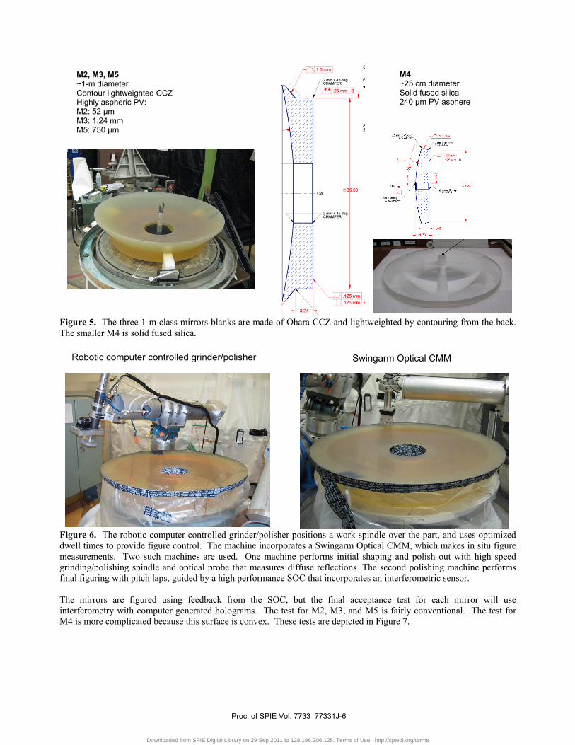
Figure 5. The three 1-m class mirrors blanks are made of Ohara CCZ and lightweighted by contouring from the back. The smaller M4 is solid fused silica.
Figure 6. The robotic computer controlled grinder/polisher positions a work spindle over the part, and uses optimized dwell times to provide figure control. The machine incorporates a Swingarm Optical CMM, which makes in situ figure measurements. Two such machines are used. One machine performs initial shaping and polish out with high speed grinding/polishing spindle and optical probe that measures diffuse reflections. The second polishing machine performs final figuring with pitch laps, guided by a high performance SOC that incorporates an interferometric sensor. The mirrors are figured using feedback from the SOC, but the final acceptance test for each mirror will use interferometry with computer generated holograms. The test for M2, M3, and M5 is fairly conventional. The test for M4 is more complicated because this surface is convex. These tests are depicted in Figure 7.
Robotic computer controlled grinder/polisher
M2, M3, M5 ~1-m diameter Contour lightweighted CCZ Highly aspheric PV: M2: 52 µm M3: 1.24 mm M5: 750 µm
M4 ~25 cm diameter Solid fused silica 240 µm PV asphere
Swingarm Optical CMM
Proc. of SPIE Vol. 7733 77331J-6
Downloaded from SPIE Digital Library on 29 Sep 2011 to 128.196.206.125. Terms of Use: http://spiedl.org/terms
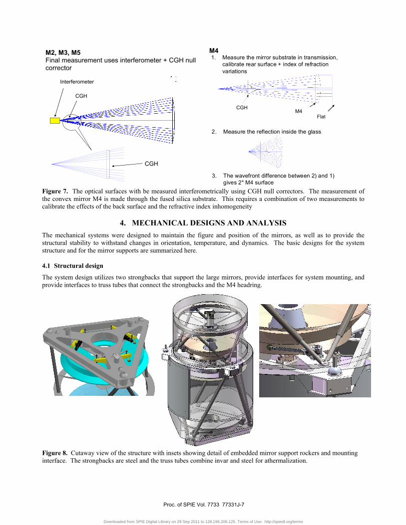
Figure 7. The optical surfaces with be measured interferometrically using CGH null correctors. The measurement of the convex mirror M4 is made through the fused silica substrate. This requires a combination of two measurements to calibrate the effects of the back surface and the refractive index inhomogeneity
4. MECHANICAL DESIGNS AND ANALYSIS The mechanical systems were designed to maintain the figure and position of the mirrors, as well as to provide the structural stability to withstand changes in orientation, temperature, and dynamics. The basic designs for the system structure and for the mirror supports are summarized here. 4.1 Structural design
The system design utilizes two strongbacks that support the large mirrors, provide interfaces for system mounting, and provide interfaces to truss tubes that connect the strongbacks and the M4 headring.
Figure 8. Cutaway view of the structure with insets showing detail of embedded mirror support rockers and mounting interface. The strongbacks are steel and the truss tubes combine invar and steel for athermalization.
Interferometer
CGH
CGH
CGH
1. Measure the mirror substrate in transmission, calibrate rear surface + index of refraction variations
2. Measure the reflection inside the glass
3. The wavefront difference between 2) and 1) gives 2* M4 surface
M4Flat
M2, M3, M5 Final measurement uses interferometer + CGH null corrector
M4
Proc. of SPIE Vol. 7733 77331J-7
Downloaded from SPIE Digital Library on 29 Sep 2011 to 128.196.206.125. Terms of Use: http://spiedl.org/terms
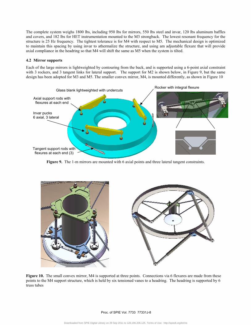
The complete system weighs 1800 lbs, including 950 lbs for mirrors, 550 lbs steel and invar, 120 lbs aluminum baffles and covers, and 182 lbs for HET instrumentation mounted to the M3 strongback. The lowest resonant frequency for the structure is 25 Hz frequency. The tightest tolerance is for M4 with respect to M5. The mechanical design is optimized to maintain this spacing by using invar to athermalize the structure, and using am adjustable flexure that will provide axial compliance in the headring so that M4 will shift the same as M5 when the system is tilted. 4.2 Mirror supports
Each of the large mirrors is lightweighted by contouring from the back, and is supported using a 6-point axial constraint with 3 rockers, and 3 tangent links for lateral support. The support for M2 is shown below, in Figure 9, but the same design has been adopted for M3 and M5. The smaller convex mirror, M4, is mounted differently, as shown in Figure 10
Figure 9. The 1-m mirrors are mounted with 6 axial points and three lateral tangent constraints.
Figure 10. The small convex mirror, M4 is supported at three points. Connections via 6 flexures are made from these points to the M4 support structure, which is held by six tensioned vanes to a headring. The headring is supported by 6 truss tubes
Axial support rods with flexures at each end
Tangent support rods with flexures at each end (3)
Rocker with integral flexure Glass blank lightweighted with undercuts
Invar pucks 6 axial, 3 lateral
Proc. of SPIE Vol. 7733 77331J-8
Downloaded from SPIE Digital Library on 29 Sep 2011 to 128.196.206.125. Terms of Use: http://spiedl.org/terms
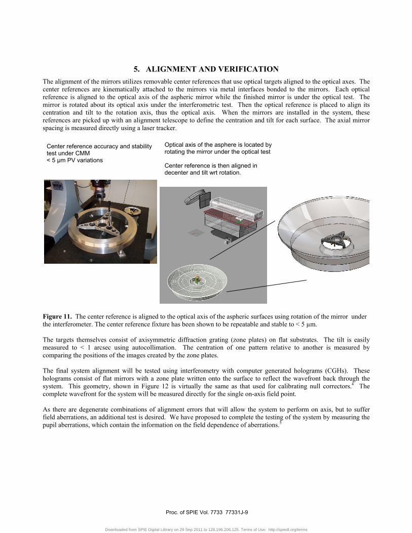
5. ALIGNMENT AND VERIFICATION The alignment of the mirrors utilizes removable center references that use optical targets aligned to the optical axes. The center references are kinematically attached to the mirrors via metal interfaces bonded to the mirrors. Each optical reference is aligned to the optical axis of the aspheric mirror while the finished mirror is under the optical test. The mirror is rotated about its optical axis under the interferometric test. Then the optical reference is placed to align its centration and tilt to the rotation axis, thus the optical axis. When the mirrors are installed in the system, these references are picked up with an alignment telescope to define the centration and tilt for each surface. The axial mirror spacing is measured directly using a laser tracker.
Figure 11. The center reference is aligned to the optical axis of the aspheric surfaces using rotation of the mirror under the interferometer. The center reference fixture has been shown to be repeatable and stable to < 5 µm. The targets themselves consist of axisymmetric diffraction grating (zone plates) on flat substrates. The tilt is easily measured to < 1 arcsec using autocollimation. The centration of one pattern relative to another is measured by comparing the positions of the images created by the zone plates. The final system alignment will be tested using interferometry with computer generated holograms (CGHs). These holograms consist of flat mirrors with a zone plate written onto the surface to reflect the wavefront back through the system. This geometry, shown in Figure 12 is virtually the same as that used for calibrating null correctors.4 The complete wavefront for the system will be measured directly for the single on-axis field point. As there are degenerate combinations of alignment errors that will allow the system to perform on axis, but to suffer field aberrations, an additional test is desired. We have proposed to complete the testing of the system by measuring the pupil aberrations, which contain the information on the field dependence of aberrations.5
Optical axis of the asphere is located by rotating the mirror under the optical test Center reference is then aligned in decenter and tilt wrt rotation.
Center reference accuracy and stability test under CMM < 5 µm PV variations
Proc. of SPIE Vol. 7733 77331J-9
Downloaded from SPIE Digital Library on 29 Sep 2011 to 128.196.206.125. Terms of Use: http://spiedl.org/terms
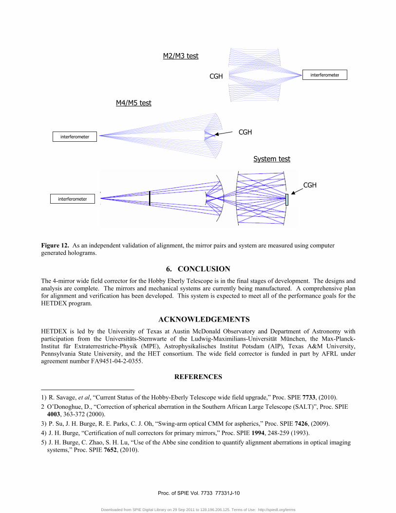
Figure 12. As an independent validation of alignment, the mirror pairs and system are measured using computer generated holograms.
6. CONCLUSION The 4-mirror wide field corrector for the Hobby Eberly Telescope is in the final stages of development. The designs and analysis are complete. The mirrors and mechanical systems are currently being manufactured. A comprehensive plan for alignment and verification has been developed. This system is expected to meet all of the performance goals for the HETDEX program.
ACKNOWLEDGEMENTS HETDEX is led by the University of Texas at Austin McDonald Observatory and Department of Astronomy with participation from the Universitäts-Sternwarte of the Ludwig-Maximilians-Universität München, the Max-Planck-Institut für Extraterrestriche-Physik (MPE), Astrophysikalisches Institut Potsdam (AIP), Texas A&M University, Pennsylvania State University, and the HET consortium. The wide field corrector is funded in part by AFRL under agreement number FA9451-04-2-0355.
REFERENCES
1) R. Savage, et al, “Current Status of the Hobby-Eberly Telescope wide field upgrade,” Proc. SPIE 7733, (2010). 2 O’Donoghue, D., “Correction of spherical aberration in the Southern African Large Telescope (SALT)”, Proc. SPIE
4003, 363-372 (2000). 3) P. Su, J. H. Burge, R. E. Parks, C. J. Oh, “Swing-arm optical CMM for aspherics,” Proc. SPIE 7426, (2009). 4) J. H. Burge, “Certification of null correctors for primary mirrors,” Proc. SPIE 1994, 248-259 (1993). 5) J. H. Burge, C. Zhao, S. H. Lu, “Use of the Abbe sine condition to quantify alignment aberrations in optical imaging
systems,” Proc. SPIE 7652, (2010).
interferometer
interferometer
interferometerCGH
CGH
CGH
M2/M3 test
M4/M5 test
System test
Proc. of SPIE Vol. 7733 77331J-10
Downloaded from SPIE Digital Library on 29 Sep 2011 to 128.196.206.125. Terms of Use: http://spiedl.org/terms


![Analysis for stress environment in the alveolar sac model · typical alveolar sac from a rabbit lung from Bachofen and Schürch [15]. A second model representing a spheri-cal sac](https://img.pdfslide.net/doc/110x75/5eb93f9ba2861569d935f22a/analysis-for-stress-environment-in-the-alveolar-sac-model-typical-alveolar-sac-from.jpg)