Embed Size (px)
Citation preview
7.2.4 Edition 10.11Technical Information · GB
www.kromschroeder.com
Burner with integrated recuperator BICR
• For direct and indirect heating equipment• Economical, energy-saving operation by virtue of internal air preheating• Great flexibility due to its maintenance-friendly modular design• Lightweight construction for minimum weight• High flue gas outlet velocity ensures uniform temperature distribution• Low pollution combustion• Direct ignition and monitoring• Low cost gas/air control is possible• High usage due to a ceramic pipe heat exchanger• Low gas and air connection pressures• As a result of its compact design it is ideal for replacing the heating elements
in radiant tubes which were originally electrically heated
BICR · Edition 10.11
2
t = To be continued
Table of contentsBurner with integrated recuperator BICR . . . . . . . . . . . . . . 1Table of contents . . . . . . . . . . . . . . . . . . . . . . . . . . . . . . . . . 21 Application . . . . . . . . . . . . . . . . . . . . . . . . . . . . . . . . . . . . . 31.1 Indirect heating. . . . . . . . . . . . . . . . . . . . . . . . . . . . . . . . . 31.2 Direct heating. . . . . . . . . . . . . . . . . . . . . . . . . . . . . . . . . . 31.3 Example applications . . . . . . . . . . . . . . . . . . . . . . . . . . . 4
1.3.1 BICR in a P radiant tube . . . . . . . . . . . . . . . . . . . . . . . . . . . . .61.3.2 BICR in a single-ended radiant tube . . . . . . . . . . . . . . . . . . .71.3.3 BICR in a single-ended radiant tube with burner control unit . . . . . . . . . . . . . . . . . . . . . . . . . . . . . . . . . . . . 81.3.4 BICR in a single-ended radiant tube with automatic burner control units . . . . . . . . . . . . . . . . . . . . . . . . . . . . . . . . . . . . . . . . . . .91.3.5 Single-stage-controlled BICR in a single-ended radiant tube with pneumatic link to the burner control unit . . . . . . . . . . 101.3.6 Single-stage-controlled BICR in a single-ended radiant tube with pneumatic link to the automatic burner control unit . 111.3.7 BICR for direct heating systems . . . . . . . . . . . . . . . . . . . . . . 121.3.8 BICR for direct heating systems with air deficiency cut-out 13
2 Mechanical construction . . . . . . . . . . . . . . . . . . . . . . . . . 142.1 Burners BICR. . . . . . . . . . . . . . . . . . . . . . . . . . . . . . . . . . 142.2 Combustion chamber / Heat exchanger TSC. . . . . . . 142.3 Exhaust-gas housing EGH . . . . . . . . . . . . . . . . . . . . . . 142.4 Rotational adapter flange. . . . . . . . . . . . . . . . . . . . . . . 15
3 Function . . . . . . . . . . . . . . . . . . . . . . . . . . . . . . . . . . . . . . 163.1 Indirect heating . . . . . . . . . . . . . . . . . . . . . . . . . . . . . . . 163.2 Direct heating . . . . . . . . . . . . . . . . . . . . . . . . . . . . . . . . 16
4 Selection . . . . . . . . . . . . . . . . . . . . . . . . . . . . . . . . . . . . . 174.1 Burners BICR. . . . . . . . . . . . . . . . . . . . . . . . . . . . . . . . . . 174.2 Exhaust-gas housing EGH . . . . . . . . . . . . . . . . . . . . . . 184.3 Ceramic tube set TSC . . . . . . . . . . . . . . . . . . . . . . . . . . 194.4 Burner design . . . . . . . . . . . . . . . . . . . . . . . . . . . . . . . . 204.5 Calculating the burner length . . . . . . . . . . . . . . . . . . . 21
5 Project planning information . . . . . . . . . . . . . . . . . . . . . 24
5.1 Indirect heating . . . . . . . . . . . . . . . . . . . . . . . . . . . . . . . 245.2 Direct heating . . . . . . . . . . . . . . . . . . . . . . . . . . . . . . . . 265.3 Installation . . . . . . . . . . . . . . . . . . . . . . . . . . . . . . . . . . . 275.4 Recommended ignition transformer . . . . . . . . . . . . . . 285.5 Nozzle-mixing burners . . . . . . . . . . . . . . . . . . . . . . . . . 285.6 Flame control. . . . . . . . . . . . . . . . . . . . . . . . . . . . . . . . . 285.7 Cooling the recuperative burner . . . . . . . . . . . . . . . . . 295.8 Emissions. . . . . . . . . . . . . . . . . . . . . . . . . . . . . . . . . . . . 305.9 Gas line connection . . . . . . . . . . . . . . . . . . . . . . . . . . . 305.9.1 System with or without pneumatic air/gas ratio control system . . . . . . . . . . . . . . . . . . . . . . . . . . . . . . . . . . . . . . . . . . . . . . 315.9.2 Systems without a pneumatic link . . . . . . . . . . . . . . . . . . . 31
6 Technical data . . . . . . . . . . . . . . . . . . . . . . . . . . . . . . . . . 326.1 Dimensions . . . . . . . . . . . . . . . . . . . . . . . . . . . . . . . . . . 336.1.1 BICR + TSC . . . . . . . . . . . . . . . . . . . . . . . . . . . . . . . . . . . . . . 336.1.2 EGH . . . . . . . . . . . . . . . . . . . . . . . . . . . . . . . . . . . . . . . . . . . 34
7 Maintenance cycles . . . . . . . . . . . . . . . . . . . . . . . . . . . . 358 Accessories . . . . . . . . . . . . . . . . . . . . . . . . . . . . . . . . . . . 36Feedback . . . . . . . . . . . . . . . . . . . . . . . . . . . . . . . . . . . . . . 38Contact . . . . . . . . . . . . . . . . . . . . . . . . . . . . . . . . . . . . . . . . 38
BICR · Edition 10.11
3
TSC
EGH
BICR
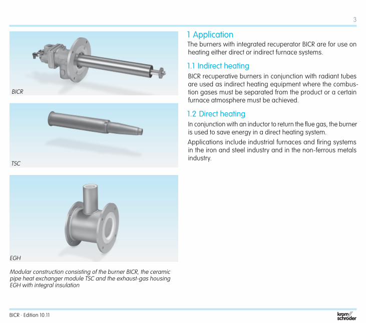
1 ApplicationThe burners with integrated recuperator BICR are for use on heating either direct or indirect furnace systems.
1 .1 Indirect heatingBICR recuperative burners in conjunction with radiant tubes are used as indirect heating equipment where the combus-tion gases must be separated from the product or a certain furnace atmosphere must be achieved.
1 .2 Direct heatingIn conjunction with an inductor to return the flue gas, the burner is used to save energy in a direct heating system.Applications include industrial furnaces and firing systems in the iron and steel industry and in the non-ferrous metals industry.
Modular construction consisting of the burner BICR, the ceramic pipe heat exchanger module TSC and the exhaust-gas housing EGH with integral insulation
BICR · Edition 10.11
4
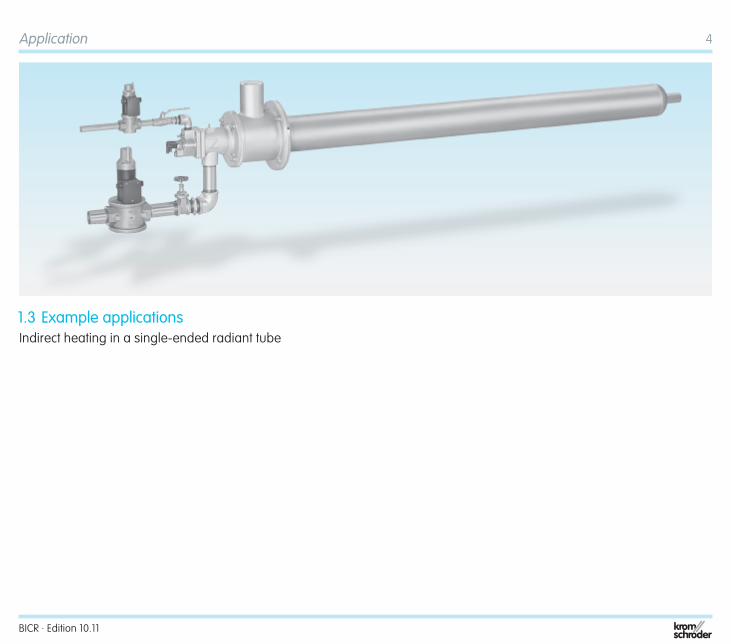
1 .3 Example applicationsIndirect heating in a single-ended radiant tube
Application
BICR · Edition 10.11
5
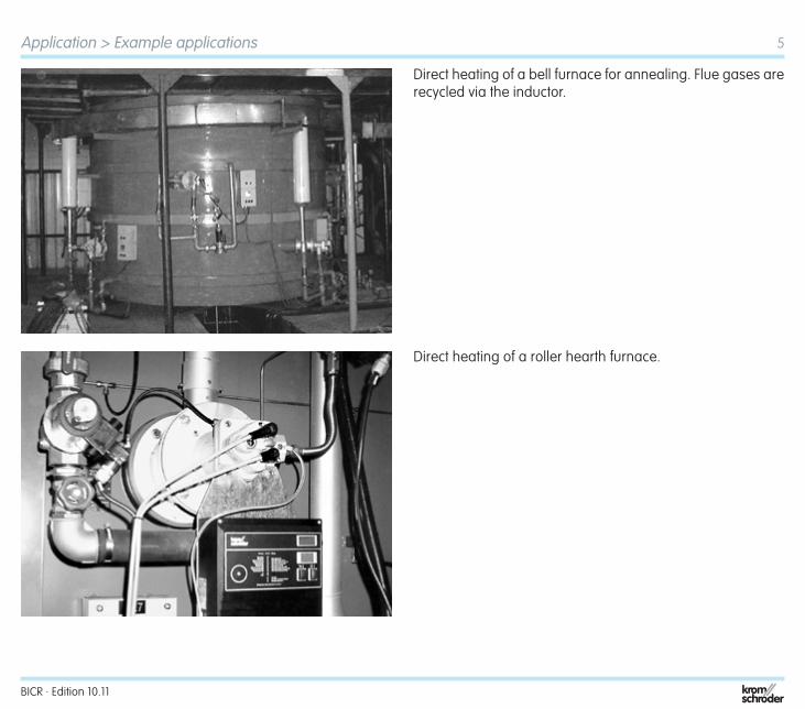
Direct heating of a bell furnace for annealing. Flue gases are recycled via the inductor.
Direct heating of a roller hearth furnace.
Application > Example applications
BICR · Edition 10.11
6
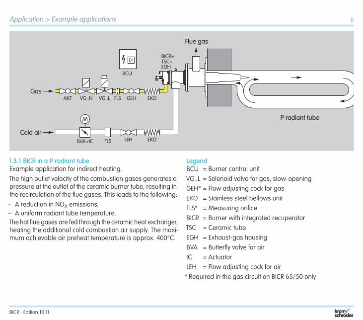
1 .3 .1 BICR in a P radiant tubeExample application for indirect heating.The high outlet velocity of the combustion gases generates a pressure at the outlet of the ceramic burner tube, resulting in the recirculation of the flue gases. This leads to the following:
– A reduction in NOX emissions,– A uniform radiant tube temperature.The hot flue gases are fed through the ceramic heat exchanger, heating the additional cold combustion air supply. The maxi-mum achievable air preheat temperature is approx. 400°C.
LegendBCU = Burner control unitVG..L = Solenoid valve for gas, slow-openingGEH* = Flow adjusting cock for gasEKO = Stainless steel bellows unitFLS* = Measuring orificeBICR = Burner with integrated recuperatorTSC = Ceramic tubeEGH = Exhaust-gas housingBVA = Butterfly valve for airIC = ActuatorLEH = Flow adjusting cock for air
* Required in the gas circuit on BICR 65/50 only
Application > Example applications
VG..N
BICR+TSC+EGH
EKOLEH
EKOGEH
FLS
FLS
BVA+IC
M
VG..L
BCU
AKT
Cold air
Flue gas
P radiant tube
Gas
BICR · Edition 10.11
7
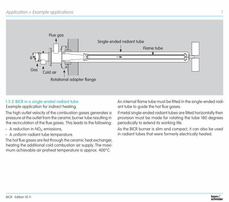
1 .3 .2 BICR in a single-ended radiant tubeExample application for indirect heating.The high outlet velocity of the combustion gases generates a pressure at the outlet from the ceramic burner tube resulting in the recirculation of the flue gases. This leads to the following:– A reduction in NOX emissions,– A uniform radiant tube temperature.The hot flue gases are fed through the ceramic heat exchanger, heating the additional cold combustion air supply. The maxi-mum achievable air preheat temperature is approx. 400°C.
An internal flame tube must be fitted in the single-ended radi-ant tube to guide the hot flue gases.If metal single-ended radiant tubes are fitted horizontally then provision must be made for rotating the tube 180 degrees periodically to extend its working life.As the BICR burner is slim and compact, it can also be used in radiant tubes that were formerly electrically heated.
GasCold air
Single-ended radiant tubeFlame tube
Rotational adapter flange
Flue gas
Application > Example applications
GasCold air
Single-ended radiant tube
Flame tube
Rotational adapter flange
Flue gas

BICR · Edition 10.11
8
1 .3 .3 BICR in a single-ended radiant tube with burner control unitC o n t r o l e x a m p l e a p p l i c a t i o n : ON/OFF with burner control unit BCU 465..L.The gas/air mixture is adjusted to the requirements of the applications using the differing parameters of air supply and air post ventilation. The pressure switch monitors the air flow in the air supply line or in the flue gas exhaust.
Application > Example applications
VR..R BICR
BCU 465..L 12
23
DI
L1, N, PE
µC
P 22 4
19 18
17 16
A
P
5 3
DI
6
26 21
VG..L
LEH EKO
GEH
EKO
PLC
BICR · Edition 10.11
9
VR..RBICR
VG..L
LEH EKO
GEH
EKO
IFS 258 89
1314
TZI
1011
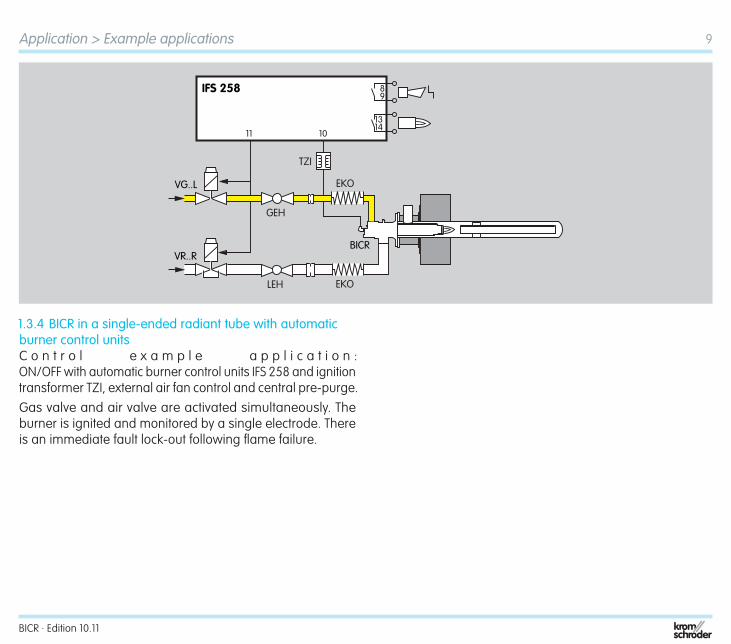
1 .3 .4 BICR in a single-ended radiant tube with automatic burner control unitsC o n t r o l e x a m p l e a p p l i c a t i o n : ON/OFF with automatic burner control units IFS 258 and ignition transformer TZI, external air fan control and central pre-purge.Gas valve and air valve are activated simultaneously. The burner is ignited and monitored by a single electrode. There is an immediate fault lock-out following flame failure.
Application > Example applications
BICR · Edition 10.11
10
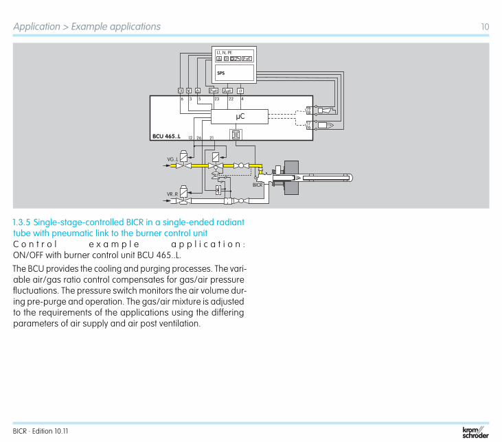
1 .3 .5 Single-stage-controlled BICR in a single-ended radiant tube with pneumatic link to the burner control unitC o n t r o l e x a m p l e a p p l i c a t i o n : ON/OFF with burner control unit BCU 465..L.The BCU provides the cooling and purging processes. The vari-able air/gas ratio control compensates for gas/air pressure fluctuations. The pressure switch monitors the air volume dur-ing pre-purge and operation. The gas/air mixture is adjusted to the requirements of the applications using the differing parameters of air supply and air post ventilation.
Application > Example applications
BICR
VG..L
VR..R
BCU 465..L 12
23
DI
L1, N, PE
µC
P 22 4
19 18
17 16
A
P
5 3
DI
6
26 21
SPS
BICR · Edition 10.11
11
BICR
VG..L
VR..R EKO
EKO
IFS 258 89
1314
TZI
1011
SPS
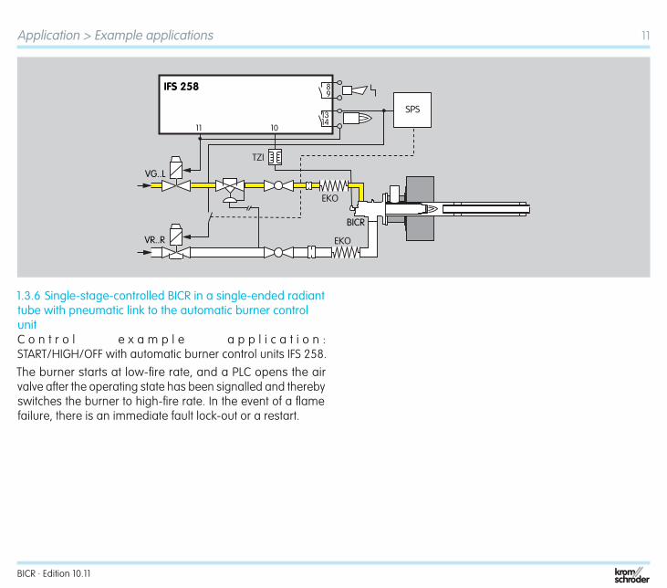
1 .3 .6 Single-stage-controlled BICR in a single-ended radiant tube with pneumatic link to the automatic burner control unitC o n t r o l e x a m p l e a p p l i c a t i o n : START/HIGH/OFF with automatic burner control units IFS 258.The burner starts at low-fire rate, and a PLC opens the air valve after the operating state has been signalled and thereby switches the burner to high-fire rate. In the event of a flame failure, there is an immediate fault lock-out or a restart.
Application > Example applications
BICR · Edition 10.11
12
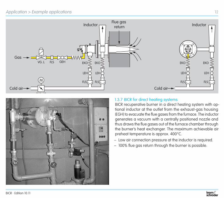
1 .3 .7 BICR for direct heating systemsBICR recuperative burner in a direct heating system with op-tional inductor at the outlet from the exhaust-gas housing (EGH) to evacuate the flue gases from the furnace. The inductor generates a vacuum with a centrally positioned nozzle and thus draws the flue gases out of the furnace chamber through the burner’s heat exchanger. The maximum achievable air preheat temperature is approx. 400°C.– Low air connection pressure at the inductor is required.– 100% flue gas return through the burner is possible.
Application > Example applications
Z I
EKO EKOVG..L EKOEKOFLS
BVA+IC
M
LEH LEH
FLS FLS
LEH LEH
FLS FLS
GEHGas
Cold air
InductorInductor
Cold air
Flue gas return
BICR · Edition 10.11
13
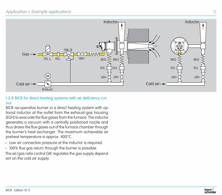
1 .3 .8 BICR for direct heating systems with air deficiency cut-outBICR recuperative burner in a direct heating system with op-tional inductor at the outlet from the exhaust-gas housing (EGH) to evacuate the flue gases from the furnace. The inductor generates a vacuum with a centrally positioned nozzle and thus draws the flue gases out of the furnace chamber through the burner’s heat exchanger. The maximum achievable air preheat temperature is approx. 400°C.– Low air connection pressure at the inductor is required.– 100% flue gas return through the burner is possible.The air/gas ratio control GIK regulates the gas supply depend-ent on the cold air supply.
Application > Example applications
Z I
LEH
FLS EKO EKO
FLS
VG..L
LEH
FLS
EKO
LEH
FLS
LEH
EKO
FLS
B VA+IC
M
GIK..B
GEHGas
Cold air
Inductor Inductor
Cold air

BICR · Edition 10.11
14
2 Mechanical constructionThe BICR burner unit is composed of three modules: burner, combustion chamber with heat exchanger and exhaust-gas housing. This structure enables easy adjustment to the respec-tive process or integration into existing systems. Maintenance and repair times are reduced and existing furnace installations can be easily converted.
2 .1 Burners BICR
The burner BICR comprises the gas connection flange, the burner air housing and the complete nozzle-mixing burner unit with its ignition and ionisation electrodes. The air guide tube stabilises the cold air flow to the burner head. Gas and air pressures can be easily measured using the gas and air measuring nipples. As of construction stage E, a measuring orifice and flow adjustment are integrated in the gas circuit.Different overall lengths enable precise adjustment to the system requirements.
2 .2 Combustion chamber / Heat exchanger TSC
A SiC ceramic tube in light-weight design serves as combus-tion chamber and, in its cylindrical part, as heat exchanger. The complete combustion of the flame takes place in the front part of the SiC tube.
2 .3 Exhaust-gas housing EGH
Interior insulating fittings protect the steel housing from thermal stress. The EGH comprises the furnace flange which is used for attaching the burner unit to the furnace. Flue gases are routed to the outside via internally insulated flue-gas nozzles.Length adjustments are possible.
BICR · Edition 10.11
15
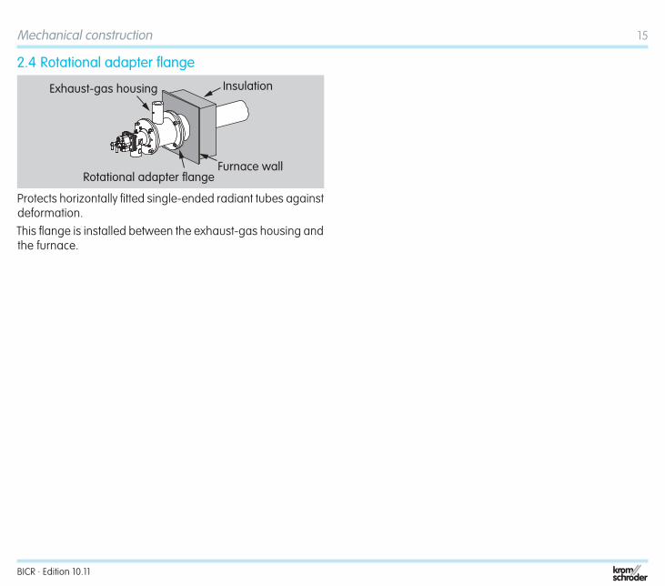
2 .4 Rotational adapter flange
Rotational adapter flange
Exhaust-gas housing Insulation
Furnace wall
Protects horizontally fitted single-ended radiant tubes against deformation.This flange is installed between the exhaust-gas housing and the furnace.
Mechanical construction

BICR · Edition 10.11
16
3 FunctionThe burner control unit opens the gas and air solenoid valves. Gas flows through the gas connection flange and air flows through the air housing into the combustion chamber as far as the nozzle-mixing burner head. The burner is directly ignited.
3 .1 Indirect heatingThe high outlet velocity of the combustion gases generates a pressure at the outlet from the ceramic burner tube result-ing in the recirculation of the flue gases. NOx emissions are reduced. The radiant tube emits an even temperature. The hot flue gases are fed through the ceramic heat exchanger to the exhaust-gas housing, heating the additional cold com-bustion air supply to max. 400°C. The combustion gases are discharged via the exhaust-gas housing.
3 .2 Direct heatingThe hot combustion gases flow straight into the furnace. An additional inductor generates a vacuum and thus draws the flue gases out of the furnace chamber through the burner’s heat exchanger. During this process, the additional cold com-bustion air supplied is heated to max. 400°C.
BICR · Edition 10.11
17
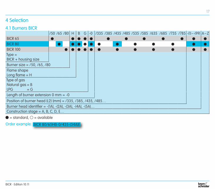
4 Selection4 .1 Burners BICR
/50 /65 /80 H B G -0 /335 /385 /435 /485 /535 /585 /635 /685 /735 /785 -(1) – -(99) A – ZBICR 65
BICR 80
BICR 100
Type =BICR + housing sizeBurner size = /50, /65, /80Flame shapeLong flame = HType of gasNatural gas = BLPG = GLength of burner extension 0 mm = -0
Position of burner head (L2) [mm] = /335, /385, /435, /485…Burner head identifier = -(1A), -(2A), -(3A), -(4A), -(5A)…Construction stage = A, B, C, D, E…
= standard, = available
Order example: BICR 80/65HB-0/435-(34A)E
BICR · Edition 10.11
18
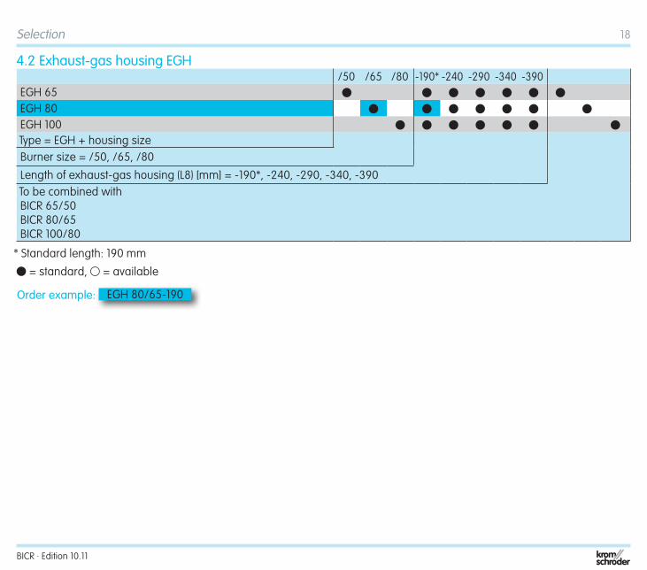
4 .2 Exhaust-gas housing EGH/50 /65 /80 -190* -240 -290 -340 -390
EGH 65
EGH 80
EGH 100 Type = EGH + housing sizeBurner size = /50, /65, /80
Length of exhaust-gas housing (L8) [mm] = -190*, -240, -290, -340, -390To be combined with BICR 65/50 BICR 80/65 BICR 100/80
= standard, = available
Order example: EGH 80/65-190
* Standard length: 190 mm
Selection

BICR · Edition 10.11
19
4 .3 Ceramic tube set TSC/50 /65 /80 B 022 030 040 -500 – -900 -550 –-950 /385 – /785 /335 – /735 -Si -1350
TSC 65
TSC 80
TSC 100 Type = TSC + housing sizeBurner size = /50, /65, /80
Tapered shape = B
Outlet diameter [mm] = 022, 030, 040Tube length (L7) [mm] -500, -600, -700, -800, -900 -550, -650, -750, -850, -950Position of burner head (L2) [mm] /385, /485, /585, /685, /785 /335, /435, /535, /635, /735Ceramic tube made of silicon-infiltrated SiC = -SiUp to 1350 °C = -1350To be combined with BICR 65/50 BICR 80/65 BICR 100/80
Order example: TSC 80/65B030-500/335-Si-1350
= standard, = available
Selection
BICR · Edition 10.11
20
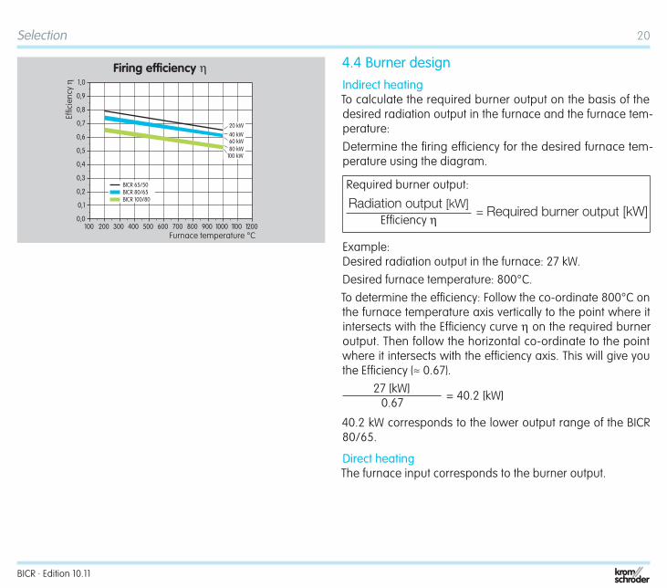
4 .4 Burner designIndirect heatingTo calculate the required burner output on the basis of the desired radiation output in the furnace and the furnace tem-perature:Determine the firing efficiency for the desired furnace tem-perature using the diagram.
Required burner output:
Radiation output [kW] = Required burner output [kW]
Efficiency η
Example: Desired radiation output in the furnace: 27 kW.Desired furnace temperature: 800°C.To determine the efficiency: Follow the co-ordinate 800°C on the furnace temperature axis vertically to the point where it intersects with the Efficiency curve η on the required burner output. Then follow the horizontal co-ordinate to the point where it intersects with the efficiency axis. This will give you the Efficiency (≈ 0.67).
27 [kW] = 40.2 [kW]0.67
40.2 kW corresponds to the lower output range of the BICR 80/65.
Direct heatingThe furnace input corresponds to the burner output.
Selection
100 200 300 400 500 600 700 800 900 1000 1100 0,0
0,1
0,2
0,3
0,4
0,5
0,6
0,7
0,8
0,9
1,0
100 kW
20 kW 40 kW 60 kW 80 kW
1200
BICR 65/50 BICR 80/65 BICR 100/80
Firing efficiency ηEf
ficie
ncy
η
Furnace temperature °C
BICR · Edition 10.11
21
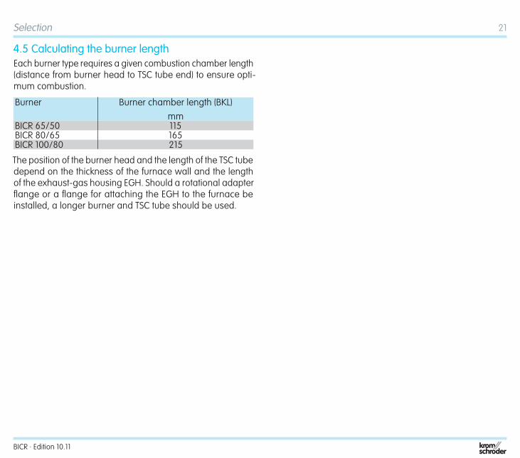
4 .5 Calculating the burner lengthEach burner type requires a given combustion chamber length (distance from burner head to TSC tube end) to ensure opti-mum combustion.
Burner Burner chamber length (BKL)mm
BICR 65/50 115BICR 80/65 165BICR 100/80 215
The position of the burner head and the length of the TSC tube depend on the thickness of the furnace wall and the length of the exhaust-gas housing EGH. Should a rotational adapter flange or a flange for attaching the EGH to the furnace be installed, a longer burner and TSC tube should be used.
Selection
BICR · Edition 10.11
22
L7L2
L D
BKL
L O
L8 x
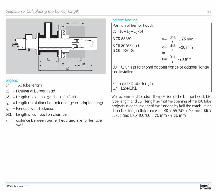
Indirect heatingPosition of burner head:L2 = L8 + LD + LO -(x)
BICR 65/50: x = BKL ± 25 mm2BICR 80/65 and BICR 100/80:
x = BKL +30 mm2tox = BKL -20 mm2
LD = 0, unless rotational adapter flange or adapter flange are installed.
Suitable TSC tube length: L7 = L2 + BKL
We recommend to adapt the position of the burner head, TSC tube length and EGH length so that the opening of the TSC tube projects into the interior of the furnace by half the combustion chamber length (tolerance on BICR 65/50: ± 25 mm, BICR 80/65 and BICR 100/80: - 20 mm / + 30 mm).
LegendL7 = TSC tube lengthL2 = Position of burner headL8 = Length of exhaust-gas housing EGHLD = Length of rotational adapter flange or adapter flangeLO = Furnace wall thicknessBKL = Length of combustion chamberx = distance between burner head and interior furnace
wall
Selection > Calculating the burner length
BICR · Edition 10.11
23
L7L2
L D
BKL
L O
L8
L A
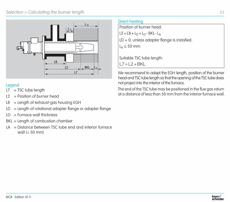
Direct heatingPosition of burner head:L2 = L8 + LD + LO - BKL - LA
LD = 0, unless adapter flange is installed.LA ≤ 50 mm.
Suitable TSC tube length:L7 = L2 + BKL
We recommend to adapt the EGH length, position of the burner head and TSC tube length so that the opening of the TSC tube does not project into the interior of the furnace.The end of the TSC tube may be positioned in the flue gas return at a distance of less than 50 mm from the interior furnace wall.
LegendL7 = TSC tube lengthL2 = Position of burner headL8 = Length of exhaust-gas housing EGHLD = Length of rotational adapter flange or adapter flangeLO = Furnace wall thicknessBKL = Length of combustion chamberLA = Distance between TSC tube end and interior furnace
wall (≤ 50 mm)
Selection > Calculating the burner length
BICR · Edition 10.11
24
R B
20 mm
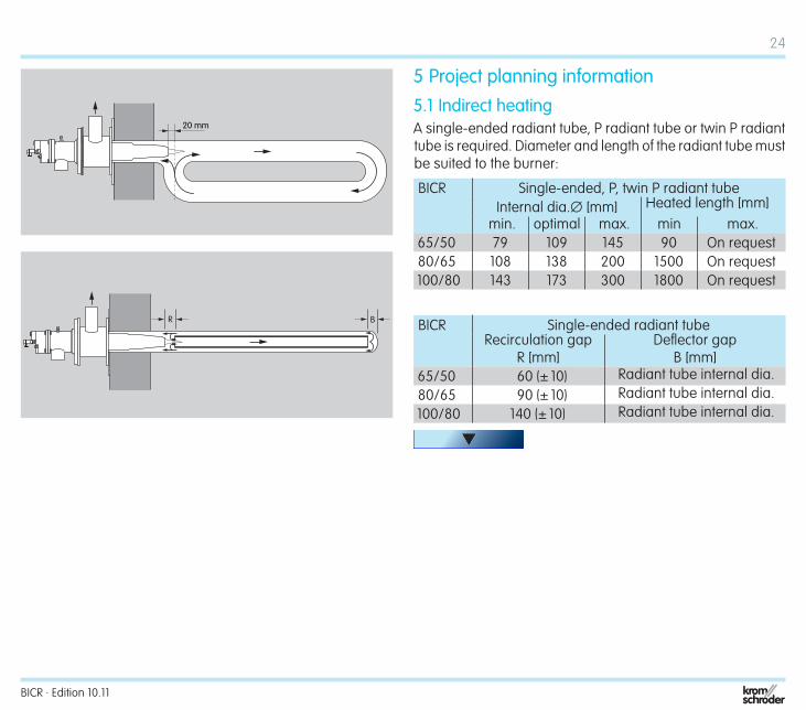
5 Project planning information5 .1 Indirect heatingA single-ended radiant tube, P radiant tube or twin P radiant tube is required. Diameter and length of the radiant tube must be suited to the burner:
BICR Single-ended, P, twin P radiant tubeInternal dia.∅ [mm] Heated length [mm]
min. optimal max. min max.65/50 79 109 145 90 On request80/65 108 138 200 1500 On request100/80 143 173 300 1800 On request
BICR Single-ended radiant tubeRecirculation gap
R [mm]Deflector gap
B [mm]65/50 60 (± 10) Radiant tube internal dia.80/65 90 (± 10) Radiant tube internal dia.100/80 140 (± 10) Radiant tube internal dia.

BICR · Edition 10.11
25
Calculating the radiation output of the radiant tube:P × η = WB P (burner output) [W]
WB (radiant tube radiation output*) [W/cm2]WB (radiant tube radiation output) [W/cm2]A [cm2] = Da [cm] × L [cm] × πDa (radiant tube external diameter) [cm]L (radiant tube length)* [cm]η (firing efficiency)
A
* Heated radiant tube length
Example:TFurnace = 700°CBurner BICR 65/50: P = 20000 WRadiant tube: Da =12,1 cmL = 150 cm π = 3,1416A = Da × L × π = 5702 cm2
20000 W × 0,7 = 2,46 W/cm2
WB = 2,46 W/cm2
5702 cm2
η (at a furnace temperature of 700°C) = 0,7
Project planning information > Indirect heating
100 200 300 400 500 600 700 800 900 1000 1100 0,0
0,1
0,2
0,3
0,4
0,5
0,6
0,7
0,8
0,9
1,0
100 kW
20 kW 40 kW 60 kW 80 kW
1200
BICR 65/50 BICR 80/65 BICR 100/80
Firing efficiency ηEf
ficie
ncy
η
Furnace temperature °C
BICR · Edition 10.11
26
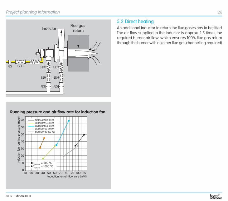
5 .2 Direct heatingAn additional inductor to return the flue gases has to be fitted. The air flow supplied to the inductor is approx. 1.5 times the required burner air flow (which ensures 100% flue gas return through the burner with no other flue gas channelling required).
Project planning information
Z I
EKO EKOVG..L EKOEKOFLS
BVA+IC
M
LEH LEH
FLS FLS
LEH LEH
FLS FLS
GEHGas
Cold air
InductorInductor
Cold air
Flue gas return
20 30 40 50 60 70 80 90
30
0
20
10
50
60
70
40
100 11510
BICR 65/50 20 kWBICR 80/65 40 kWBICR 80/65 60 kWBICR 100/80 80 kWBICR 100/80 100 kW
Running pressure and air flow rate for induction fan
TFurnace = 600 °CTFurnace = 1000 °C
Indu
ctio
n fa
n ru
nnin
g pr
essu
re [m
bar]
Induction fan air flow rate [m3/h]
BICR · Edition 10.11
27
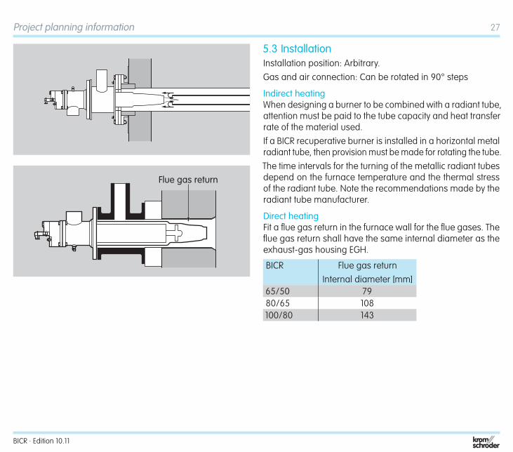
5 .3 InstallationInstallation position: Arbitrary.Gas and air connection: Can be rotated in 90° steps
Indirect heatingWhen designing a burner to be combined with a radiant tube, attention must be paid to the tube capacity and heat transfer rate of the material used.If a BICR recuperative burner is installed in a horizontal metal radiant tube, then provision must be made for rotating the tube.The time intervals for the turning of the metallic radiant tubes depend on the furnace temperature and the thermal stress of the radiant tube. Note the recommendations made by the radiant tube manufacturer.
Direct heatingFit a flue gas return in the furnace wall for the flue gases. The flue gas return shall have the same internal diameter as the exhaust-gas housing EGH.
BICR Flue gas returnInternal diameter [mm]
65/50 7980/65 108100/80 143
Project planning information
Flue gas return
BICR · Edition 10.11
28
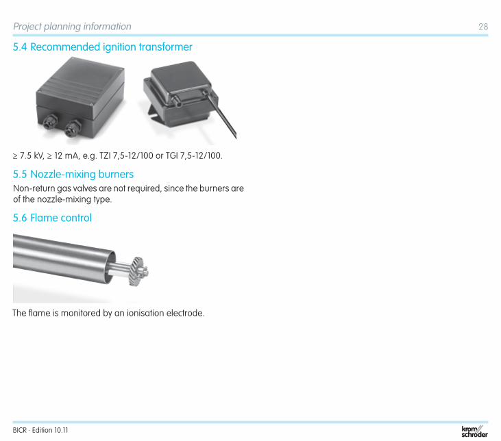
5 .4 Recommended ignition transformer
≥ 7.5 kV, ≥ 12 mA, e.g. TZI 7,5-12/100 or TGI 7,5-12/100.
5 .5 Nozzle-mixing burnersNon-return gas valves are not required, since the burners are of the nozzle-mixing type.
5 .6 Flame control
The flame is monitored by an ionisation electrode.
Project planning information
BICR · Edition 10.11
29
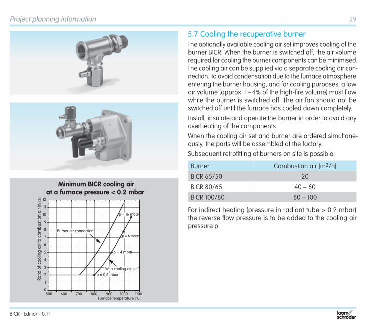
5 .7 Cooling the recuperative burnerThe optionally available cooling air set improves cooling of the burner BICR. When the burner is switched off, the air volume required for cooling the burner components can be minimised. The cooling air can be supplied via a separate cooling air con-nection. To avoid condensation due to the furnace atmosphere entering the burner housing, and for cooling purposes, a low air volume (approx. 1 – 4% of the high-fire volume) must flow while the burner is switched off. The air fan should not be switched off until the furnace has cooled down completely.Install, insulate and operate the burner in order to avoid any overheating of the components.When the cooling air set and burner are ordered simultane-ously, the parts will be assembled at the factory.Subsequent retrofitting of burners on site is possible.
Burner Combustion air [m3/h]
BICR 65/50 20
BICR 80/65 40 – 60
BICR 100/80 80 – 100
For indirect heating (pressure in radiant tube > 0.2 mbar) the reverse flow pressure is to be added to the cooling air pressure p.
Project planning information
0
1
2
3
4
5
6
7
8
9
10
11
12
500 600 700 800 900 1000 1100
p = 0,6 mbar
p = 4 mbar
p = 6 mbar
p = 16 mbar
Ratio
of c
oolin
g ai
r to
com
bust
ion
air i
n [%
]
Burner air connection
With cooling air set
Furnace temperature [°C]
Minimum BICR cooling airat a furnace pressure < 0.2 mbar

BICR · Edition 10.11
30
5 .8 EmissionsEmissions do not exceed the limits stipulated by the German Technical Instructions on Air Quality Control.NOx values depend on the temperature, combustion chamber, furnace chamber, λ value and output.If operated with LPG, NOx values are approx. 25% higher.
5 .9 Gas line connectionTo ensure accurate measurements of the pressure differential on the integrated gas measuring orifice for burners BICR 80/65 and BICR 100/80 as from construction stage E, the following applies for the design of the gas connection:
– Ensure undisturbed flow to the gas connection on the burner for a distance of ≥ 5 DN.
– Use a flexible tube unit with the same nominal dimen-sions as the gas connection on the burner.
– Use a pipe bend up to an angle of 90° with the same nominal dimensions as the gas connection on the burner.
– Only use reducing nipples with an external thread at both ends in order to reduce the nominal diameter on the burner (e.g. from 1" to ¾").
To ensure optimum flow, to avoid incorrect measurements and to enable burner operation with excess gas, we recommend the following:
– Do not screw the manual valve directly into the burner.
Project planning information
300 400 500 600 700 800 900 1000
80 kW 100 kW 40 kW 60 kW 20 kW 40 kW
300
NO
x (m
g/m
3 ref
5%
O2)
60
80
100
120
140
160
180
NO
x (p
pm re
f 2%
O2)
200
100
250
200
150
350
NOx emissions, natural gas
Furnace temperature °C
Single-ended radiant tube:
P radiant tube:
BICR · Edition 10.11
31
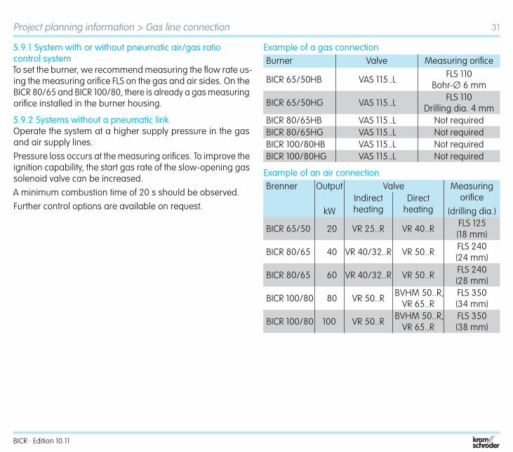
Example of a gas connectionBurner Valve Measuring orifice
BICR 65/50HB VAS 115..L FLS 110 Bohr-∅ 6 mm
BICR 65/50HG VAS 115..L FLS 110 Drilling dia. 4 mm
BICR 80/65HB VAS 115..L Not requiredBICR 80/65HG VAS 115..L Not requiredBICR 100/80HB VAS 115..L Not requiredBICR 100/80HG VAS 115..L Not required
Example of an air connectionBrenner Output Valve Measuring
orifice(drilling dia.)kW
Indirect heating
Direct heating
BICR 65/50 20 VR 25..R VR 40..R FLS 125 (18 mm)
BICR 80/65 40 VR 40/32..R VR 50..R FLS 240 (24 mm)
BICR 80/65 60 VR 40/32..R VR 50..R FLS 240 (28 mm)
BICR 100/80 80 VR 50..R BVHM 50..R, VR 65..R
FLS 350 (34 mm)
BICR 100/80 100 VR 50..R BVHM 50..R, VR 65..R
FLS 350 (38 mm)
5 .9 .1 System with or without pneumatic air/gas ratio control systemTo set the burner, we recommend measuring the flow rate us-ing the measuring orifice FLS on the gas and air sides. On the BICR 80/65 and BICR 100/80, there is already a gas measuring orifice installed in the burner housing.
5 .9 .2 Systems without a pneumatic linkOperate the system at a higher supply pressure in the gas and air supply lines.Pressure loss occurs at the measuring orifices. To improve the ignition capability, the start gas rate of the slow-opening gas solenoid valve can be increased.A minimum combustion time of 20 s should be observed.Further control options are available on request.
Project planning information > Gas line connection
BICR · Edition 10.11
32
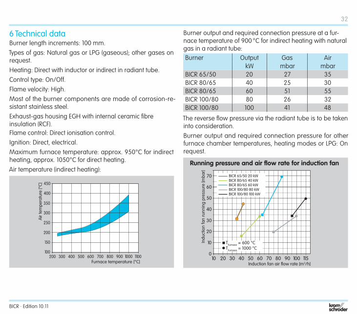
6 Technical dataBurner length increments: 100 mm.Types of gas: Natural gas or LPG (gaseous); other gases on request.Heating: Direct with inductor or indirect in radiant tube.Control type: On/Off.Flame velocity: High.Most of the burner components are made of corrosion-re-sistant stainless steel.Exhaust-gas housing EGH with internal ceramic fibre insulation (RCF).Flame control: Direct ionisation control.Ignition: Direct, electrical.Maximum furnace temperature: approx. 950°C for indirect heating, approx. 1050°C for direct heating.Air temperature (indirect heating):
100
150
200
250
300
350
200 300 400 500 600 700 800 1100
400
450
900 1000 Furnace temperature [°C]
Air
tem
pera
ture
[°C]
Burner output and required connection pressure at a fur-nace temperature of 900 °C for indirect heating with natural gas in a radiant tube: Burner Output Gas Air
kW mbar mbarBICR 65/50 20 27 35BICR 80/65 40 25 30BICR 80/65 60 51 55BICR 100/80 80 26 32BICR 100/80 100 41 48
The reverse flow pressure via the radiant tube is to be taken into consideration.Burner output and required connection pressure for other furnace chamber temperatures, heating modes or LPG: On request.
20 30 40 50 60 70 80 90
30
0
20
10
50
60
70
40
100 11510
BICR 65/50 20 kWBICR 80/65 40 kWBICR 80/65 60 kWBICR 100/80 80 kWBICR 100/80 100 kW
Running pressure and air flow rate for induction fan
TFurnace = 600 °CTFurnace = 1000 °C
Indu
ctio
n fa
n ru
nnin
g pr
essu
re [m
bar]
Induction fan air flow rate [m3/h]
BICR · Edition 10.11
33
Z I
D
L4 L7
D1
GA
hH
L3L6
L5
S d2
D2k2
n2LAF
L2
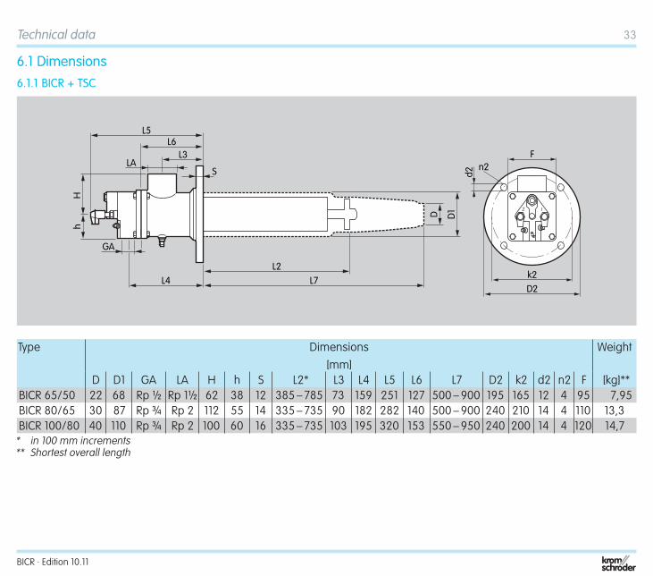
6 .1 Dimensions6 .1 .1 BICR + TSC
Type Dimensions[mm]
Weight
D D1 GA LA H h S L2* L3 L4 L5 L6 L7 D2 k2 d2 n2 F [kg]**BICR 65/50 22 68 Rp ½ Rp 1½ 62 38 12 385 – 785 73 159 251 127 500 – 900 195 165 12 4 95 7,95BICR 80/65 30 87 Rp ¾ Rp 2 112 55 14 335 – 735 90 182 282 140 500 – 900 240 210 14 4 110 13,3BICR 100/80 40 110 Rp ¾ Rp 2 100 60 16 335 – 735 103 195 320 153 550 – 950 240 200 14 4 120 14,7
* in 100 mm increments ** Shortest overall length
Technical data
BICR · Edition 10.11
34
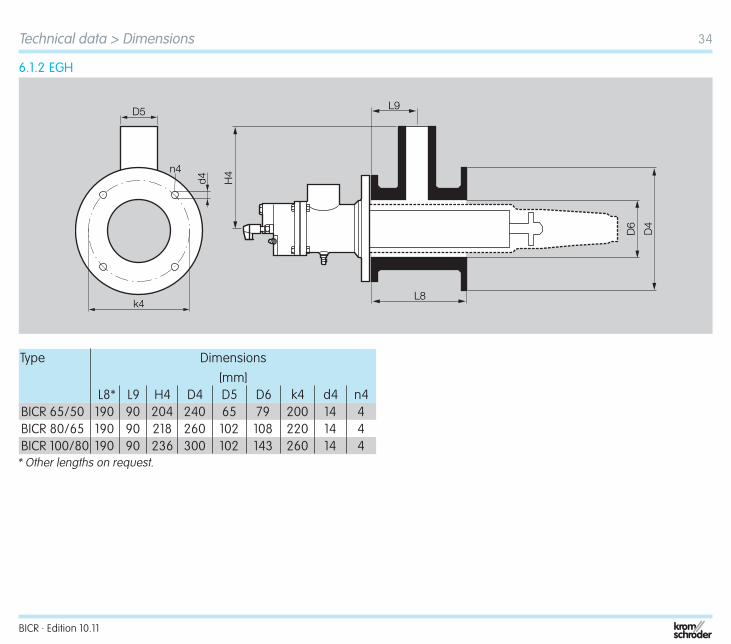
L9D5
D4
d4
n4
H4
L8k4
D6
Type Dimensions[mm]
L8* L9 H4 D4 D5 D6 k4 d4 n4BICR 65/50 190 90 204 240 65 79 200 14 4BICR 80/65 190 90 218 260 102 108 220 14 4BICR 100/80 190 90 236 300 102 143 260 14 4
* Other lengths on request.
6 .1 .2 EGH
Technical data > Dimensions

BICR · Edition 10.11
35
7 Maintenance cyclesTwice per year, but if the media are highly contaminated, this interval should be reduced.
BICR · Edition 10.11
36
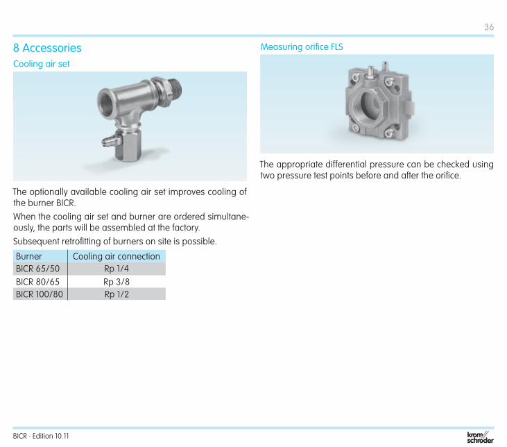
8 AccessoriesCooling air set
The optionally available cooling air set improves cooling of the burner BICR.When the cooling air set and burner are ordered simultane-ously, the parts will be assembled at the factory.Subsequent retrofitting of burners on site is possible.
Burner Cooling air connectionBICR 65/50 Rp 1/4BICR 80/65 Rp 3/8BICR 100/80 Rp 1/2
Measuring orifice FLS
The appropriate differential pressure can be checked using two pressure test points before and after the orifice.
BICR · Edition 10.11
37
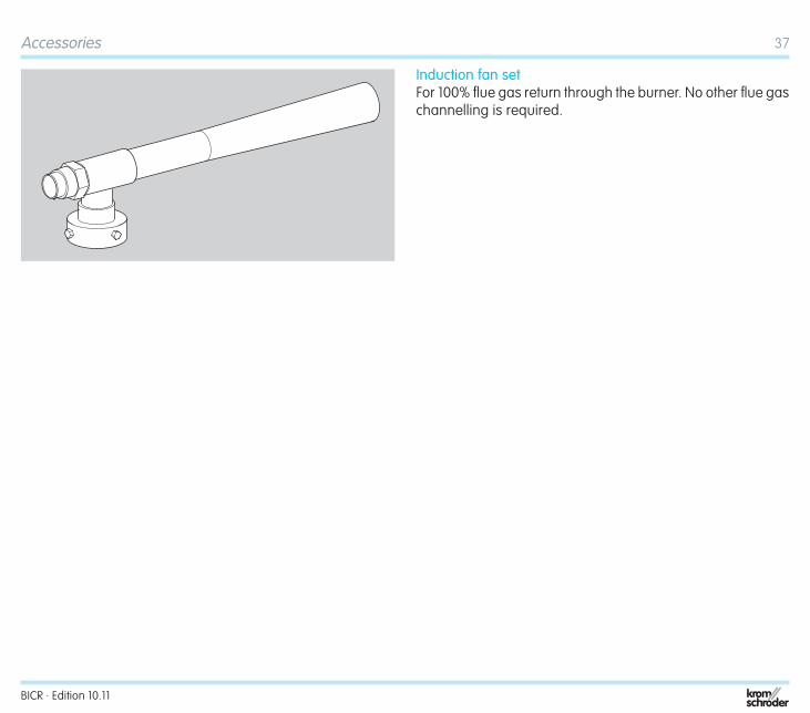
Induction fan setFor 100% flue gas return through the burner. No other flue gas channelling is required.
Accessories

BICR · Edition 10.11
38
FeedbackFinally, we are offering you the opportunity to assess this “Technical Information (TI)” and to give us your opinion, so that we can improve our documents further and suit them to your needs.
ClarityFound information quicklySearched for a long timeDidn’t find informationWhat is missing?
ComprehensionCoherentToo complicatedNo answer
ScopeToo littleSufficientToo wideNo answer
No answer
NavigationI can find my way aroundI got “lost”No answer
UseTo get to know the productTo choose a productPlanningTo look for information
My scope of functionsTechnical departmentSalesNo answer
Remarks
(Adobe Reader 7 or higher required) www.adobe.com
Elster GmbH Postfach 2809 · 49018 Osnabrück Strotheweg 1 · 49504 Lotte (Büren) GermanyT +49 541 1214-0 F +49 541 1214-370 [email protected] www.elster.com
The current addresses of our international agents are available on the Internet:www.kromschroeder.de/index.php?id=718&L=1
We reserve the right to make technical modifications in the interests of progress.Copyright © 2011 Elster Group All rights reserved.
0325
0555
Feedback
Contact


![BRP Guns · MG42 Recevier Front Recuperator Mount Hole/Slot 13.879 [352.54mm] R.11 [R2.81mm].221 [5.61mm].625 [15.88mm] Current location of front recuperator mount hole realtive to](https://img.pdfslide.net/doc/110x75/5ff543d35f7775336b5bf99a/brp-guns-mg42-recevier-front-recuperator-mount-holeslot-13879-35254mm-r11.jpg)