Embed Size (px)
Citation preview
1
RADIANT RECUPERATOR: MODELLING AND DESIGN
Suzana D. KNEŽEVIĆa, Rade M. KARAMARKOVIĆ
a*, Vladan M. KARAMARKOVIĆ
a,
Nenad P. STOJIĆa
aFaculty of Mechanical and Civil Engineering in Kraljevo, University of Kragujevac, Serbia
* Corresponding author; E-mail: [email protected]
Recuperators are frequently used in glass production and metallurgical
processes to preheat combustion air by heat exchange with high temperature
flue gases. Mass and energy balances of a 15 m high, concurrent radiant
recuperator used in a glass fiber production process are given. The balances
are used: (i) for validation of a cell modelling method that predicts the
performance of different recuperator designs and (ii) for finding a simple
solution to improve the existing recuperator. Three possible solutions are
analyzed: (i) to use the existing recuperator as a countercurrent one, (ii) to
add an extra cylinder over the existing construction and make a system that
consists of a central pipe and two concentric annular ducts. In the latter, two
air streams flow in opposite directions, whereas air in the inner annular
passage flows concurrently or countercurrently to flue gases. Compared
with the concurrent recuperator, the countercurrent has only one drawback:
the interface temperature is higher at the bottom. The advantages are: lower
interface temperature at the top where the material is under maximal load,
higher efficiency and smaller pressure drop. Both concurrent and
countercurrent double pipe-in-pipe systems are only slightly more efficient
than pure concurrent and countercurrent recuperators, respectively. Their
advantages are smaller interface temperatures whereas the disadvantages
are their costs and pressure drops. To implement these solutions, the
average velocities should be: for flue gas around 5 m/s, for air in the first
passage less than 2 m/s, and for air in the second passage more than 25 m/s.
Key words: recuperator, radiation, convection, heat transfer, concurrent,
countercurrent, double pipe-in-pipe system
1. Introduction
The higher the temperature, the larger the heat potential to perform work, i.e. its exergy. The
maximum theoretical efficiency for the conversion of heat into power is given by the formula for a
reversible Carnot process: , which means that 80% of the heat at 1217 °C could
be theoretically transferred into power when the environment is at 25 °C. The highly valuable heat at
high temperatures leaves metallurgical and glass production furnaces as the sensible heat of flue gases.
In a glass fiber production process, flue gas exit temperatures greater than 1200 °C are usual [1]. The
preferable use of high temperature heat is for power production, but in these industries it is more
energy efficient, economically justified, and technically simpler to use this heat to maintain high
2
temperatures of technological processes. This is achieved by recuperators, in which combustion air is
preheated by heat exchange with hot flue gases. The use of preheated air increases combustion
temperature and the process efficiency [2]. Its use decreases exergy destruction due to internal thermal
energy exchange (heat transfer), which is the major source of irreversibilities in an oxidation process
[3].
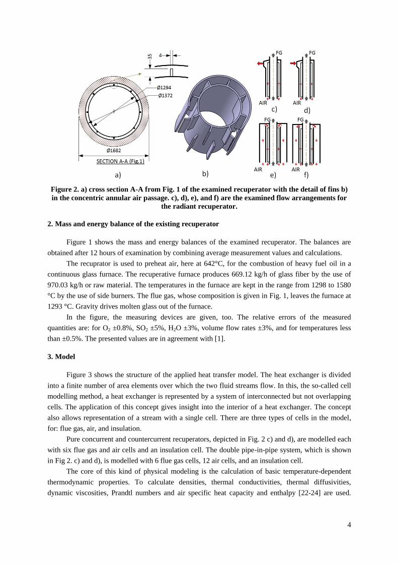
The basis for this work is a 15 m high recuperator used downstream of a glass fiber kiln, which
is shown in Figs. 1 and 2. It is a concurrent pipe-in-pipe radiant heat exchanger in which both fluids:
flue gas and combustion air, enter from the bottom and exit at the top. Flue gas flows through the
central pipe and combustion air flows through the annulus, which is shown in Fig. 2 a) and b). The
annulus has 8 fins over the perimeter of the outer surface of the inner cylinder. These fins are 50 cm
long and are placed over the entire annulus length. They influence the heat transfer but are placed
primarily to facilitate assemblage, secure the proper distance between the cylinders, and prevent
buckling and bulging of the innermost cylinder. The structure hangs supported from the above, which
means that the maximum load on the material is at the top of the recuperator. To secure material
strength in this zone a cooling air is introduced just above the combustion air exit, as can be seen in
Fig. 1. The lowest interface temperature produces the longest useful, life-time for a recuperator, and is
the main reason why concurrent arrangement is the most popular for recuperators [4]. The examined
recuperator is built from high temperature resistant chrome nickel steel. Recuperators are classified
according to: (i) their material: metallic or ceramic, (ii) dominant mode of heat transfer: convective,
radiant, and combined (convection and radiation) recuperators etc. Convective recupeators are well
documented, whereas due to its commercial value and confidential nature of industry, little
information is available in open literature on metallic recuperators [5]. Two types of radiant
recuperators are frequently used: pipe-in-pipe, depicted in Fig. 1 and explained in the previous
chapter, and tubular or cage type recuperator [5]. The latter type is used for high pressures and consists
of tubes, often removable, arranged on the large diameter circle. To improve the durability and
effectiveness of radiant recuperators, the research in the field spreads in:
- developing new materials and coatings; Above 1100 °C ceramic material is a better technological
solution for durable heat exchangers but is prone to fouling [6]. Luzzato et al. [7] presented a high
temperature heat exchanger with the main heat transfer parts made out of ceramic matrix
composite materials. Metallic radiant recuperators are built of high temperatures refractory steels
and alloys of nickel, cobalt and chromium [5,8,9]. To obtain good resistance to high temperature
corrosion, erosion and wear different coatings are used. The examples of coatings are nickel base
brazing filler alloy and high-velocity oxy-fuel thermal sprayed Cr3C2-NiCr [10], as cited by [5].
- developing new designs; The examples are recuperative burners [11,12], heat pipe recuperator
[13] cited by [5], radiant recuperator with additional air passage that lowers excessive recuperator
surface temperature and improves its effectiveness [14-16]. In the patent [16], the authors
empirically recommended the ratio of the cross-sectional areas of the outer and the inner annular
combustion air-circulating passages at 5:1 and stated that the ratio as small as 4:1 is acceptable,
too. However, they did not give a general recommendation for the air velocity in these passages
regardless of the capacity.
- modification of the existing designs; They are introduced to ease assembling, give more strength
at high temperatures and improve radiative heat transfer from flue gases and convective heat
transfer to combustion air. The latter is improved by longitudinal fins [17], with oblique wavy
3
walls [18], or vanes that impart twisting motion [19]. Radiation from flue gases is improved by
inserting a flat metal surface [4] or an elongated central ceramic core [16].
- construction modelling; Sharma et al. developed models for concurrent [20] and countercurrent
[21] radiant recuperators to consider their performances and account for heat transfer processes.
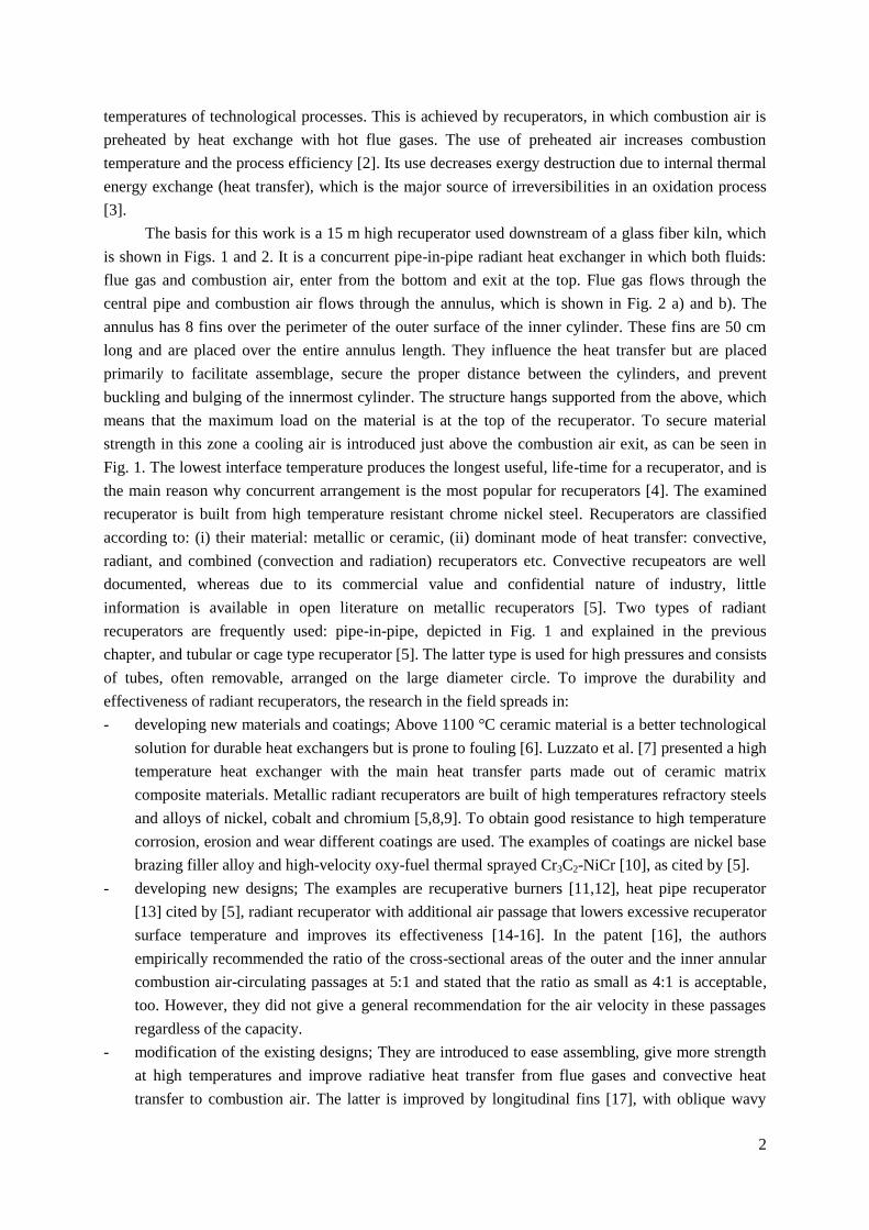
Figure 1. Measuring points, instruments, and results for the examined radiant recuperator.
The goal is: (i) to give mass and energy balances of the recuperator, (ii) to present a
mathematical cell method that can be used for modelling radiant recuperators, (iii) to find a simple
solution to improve the existing design, and (iv) to give recommendations and conditions for the use
of a double pipe-in-pipe system (double air annulus) in this kind of heat exchangers. The analyzed
flow configurations for the improvement of the examined recuperator are shown in Fig. 2 c)-f): c)
represents the existing configuration, d) countercurrent flow configuration e) depicts the configuration
recommended by [14-16], whichis made of three concentric pipes. In this kind of recuperators (Fig. 2
e)), a single air stream flows in opposite directions through two concentric annuluses, whereas flue gas
flows through the central pipe. Two flow arrangements of this kind are analyzed: one where air in the
inner annulus flows countercurrently (Fig. 2 e)) and the other where it flows concurrently (Fig. 2 f)) to
flue gases. The examined configurations are compared, and the pros and cons as well as the
recommendation for their use are discussed in detail.
4
Figure 2. a) cross section A-A from Fig. 1 of the examined recuperator with the detail of fins b)
in the concentric annular air passage. c), d), e), and f) are the examined flow arrangements for
the radiant recuperator.
2. Mass and energy balance of the existing recuperator
Figure 1 shows the mass and energy balances of the examined recuperator. The balances are
obtained after 12 hours of examination by combining average measurement values and calculations.
The recuprator is used to preheat air, here at 642°C, for the combustion of heavy fuel oil in a
continuous glass furnace. The recuperative furnace produces 669.12 kg/h of glass fiber by the use of
970.03 kg/h or raw material. The temperatures in the furnace are kept in the range from 1298 to 1580
°C by the use of side burners. The flue gas, whose composition is given in Fig. 1, leaves the furnace at
1293 °C. Gravity drives molten glass out of the furnace.
In the figure, the measuring devices are given, too. The relative errors of the measured
quantities are: for O2 ±0.8%, SO2 ±5%, H2O ±3%, volume flow rates ±3%, and for temperatures less
than ±0.5%. The presented values are in agreement with [1].
3. Model
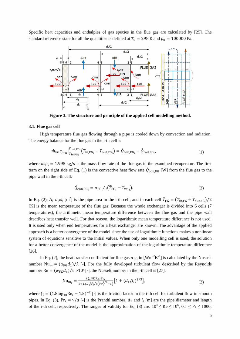
Figure 3 shows the structure of the applied heat transfer model. The heat exchanger is divided
into a finite number of area elements over which the two fluid streams flow. In this, the so-called cell
modelling method, a heat exchanger is represented by a system of interconnected but not overlapping
cells. The application of this concept gives insight into the interior of a heat exchanger. The concept
also allows representation of a stream with a single cell. There are three types of cells in the model,
for: flue gas, air, and insulation.
Pure concurrent and countercurrent recuperators, depicted in Fig. 2 c) and d), are modelled each
with six flue gas and air cells and an insulation cell. The double pipe-in-pipe system, which is shown
in Fig 2. c) and d), is modelled with 6 flue gas cells, 12 air cells, and an insulation cell.
The core of this kind of physical modeling is the calculation of basic temperature-dependent
thermodynamic properties. To calculate densities, thermal conductivities, thermal diffusivities,
dynamic viscosities, Prandtl numbers and air specific heat capacity and enthalpy [22-24] are used.
5
Specific heat capacities and enthalpies of gas species in the flue gas are calculated by [25]. The
standard reference state for all the quantities is defined at and .
Figure 3. The structure and principle of the applied cell modelling method.
3.1. Flue gas cell
High temperature flue gas flowing through a pipe is cooled down by convection and radiation.
The energy balance for the flue gas in the i-th cell is
, (1)
where is the mass flow rate of the flue gas in the examined recuperator. The first
term on the right side of Eq. (1) is the convective heat flow rate [W] from the flue gas to the
pipe wall in the i-th cell:
. (2)
In Eq. (2), Ai=d1πli [m2] is the pipe area in the i-th cell, and in each cell
[K] is the mean temperature of the flue gas. Because the whole exchanger is divided into 6 cells (7
temperatures), the arithmetic mean temperature difference between the flue gas and the pipe wall
describes heat transfer well. For that reason, the logarithmic mean temperature difference is not used.
It is used only when end temperatures for a heat exchanger are known. The advantage of the applied
approach is a better convergence of the model since the use of logarithmic functions makes a nonlinear
system of equations sensitive to the initial values. When only one modelling cell is used, the solution
for a better convergence of the model is the approximation of the logarithmic temperature difference
[26].
In Eq. (2), the heat transfer coefficient for flue gas in [Wm-2
K-1
] is calculated by the Nusselt
number [-]. For the fully developed turbulent flow described by the Reynolds
number >104 [-], the Nusselt number in the i-th cell is [27]:
, (3)
where [-] is the friction factor in the i-th cell for turbulent flow in smooth
pipes. In Eq. (3), [-] is the Prandtl number, and [m] are the pipe diameter and length
of the i-th cell, respectively. The ranges of validity for Eq. (3) are: 104
≤ Re ≤ 106; 0.1 ≤ Pr ≤ 1000;
6
d1/li ≤ 1. The physical properties of the fluids are referred to the mean temperature in the i-th cell. The
properties of flue gas are affected by temperature, but when the gas is cooled in the pipe, the effect of
temperature dependent property variations should not be taken into account.
The second term on the right side of Eq. (1), [W] represents the radiative heat transfer
from the flue gas mixture onto the circumference of the enclosing pipe [28]:
, (4)
where is the Stefan–Boltzmann constant, is the wall
emissivity for stainless steel in furnace service [29]. The radiative heat transfer rate in the i-th cell is
calculated by the use of the medium gas [K] and the wall temperatures [K] in the cell.
For a mixture of H2O and CO2 at a total pressure of p=1 bar for pH2O/pCO2=1, the temperatures
between 1,100 K < Tg < 1,800 K, and the equivalent layer thickness between 0.2 m < seq < 6 m, the
total emissivity is [30] (cited by [28]):
, (5)
, (6)
where the coefficients in Eqs. (5) and (6) are: b11=0.130, b12=0.595, b13=0.275, b21=0.265, b22=-0.15,
b23=-0.115, k1=0 1/mbar, k2=0.824 1/mbar, k3=25.91 1/mbar [28].
The corresponding degrees of absorption Av [-] in Eq. (4) are readily calculated by using the
same Eqs. (5) and (6) when the temperature of the emitting wall is used instead of the temperature
of the gas [28]. For the examined recuperator, the partial pressure of H2O is pH2O = 0.1171 bar,
whereas for CO2 it is pCO2 = 0.1324 bar (0.1313+0.0011) (see Fig. 1). The small SO2 partial pressures
of the combustion gases are covered by the CO2 partial pressures [31]. seq [m] is the equivalent layer
thickness, which for the flue gas cylindrical cell (d1=1.294 m and l=2.5 m (see Figs. 1 and 2)) is 0.76
[28].
In the i-th section, the heat is transferred by convection and radiation to the pipe wall. The heat
is then transmitted through the wall by the conduction heat flow rate [W] to the annulus
through which air flows. The heat rate balance for the cell wall (surface 1-1 in Fig. 3) is:
, (7)
where is the thermal conductivity for the pipe [32].
3.2. Air cell
The air flowing the through concentric annular duct is heated by convective heat transfer rates
from the inner and outer cylinders (see Fig. 3). The energy rate balance for the air flow in the i-th cell
is:
(8)
7
where 1.815 kg/s is the mass flow rate of air (see Fig. 1), [W] and [W] are the
convective heat transfer rates from the inner and outer surface of the annulus, respectively. For the i-th
air cell they are calculated by:
, (9)
. (10)
In these equations, and in [m2] are the areas of the inner and outer cylinder
that form the annulus, respectively. To calculate convective heat transfer rates in each cell, the
arithmetic mean air temperature [K] is used. The wall temperatures in the
annulus are at the outer diameter of the inner cylinder [K] and at the inner diameter of the outer
cylinder [K].
A model given in [33] that calculates the heat transfer in concentric annular ducts for fully
developed turbulent flow is used to calculate the heat transfer coefficient [Wm-2K-1] in each air
cell. In the model, the dimensionless numbers for the i-th cell are determined by the use
of the hydraulic diameter given by [m].
The air velocity [ms-1] in the i-th cell is calculated by
, (11)
where [-] is the number or rectangular fins. [m], and [m] are the height and the width of a fin,
respectively (see Fig. 2). The physical properties of all the quantities in the model are referred to the
mean air temperature in the cell.
For a fully developed turbulent flow Re>104 in a concentric annular duct, the modified equation
of Petukhov and Kirilov [34] (as stated in [33]) is used:
.
(12)
In Eq. (12) the coefficient [-] is calculated in each cell i by
. In each cell i, the friction factor [-] depends on the ratio [-] and is
determined by [33] with:
. (13)
For the boundary condition ‘‘heat transfer from both walls”, which is valid for the examined
recuperator, the coefficient [-] in Eq. (12) for the i-th cell is determined by [33]
. (14)
In each cell, Eq. (12) that calculates the Nusselt number is modified by the use of the multiplier
[33] [-], which takes into account the variation of fluid properties with temperature.
8
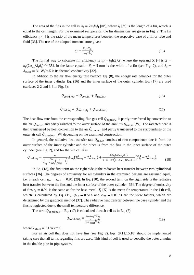
The area of the fins in the cell is [m2], where [m] is the length of a fin, which is
equal to the cell length. For the examined recuperator, the fin dimensions are given in Fig. 2. The fin
efficiency [-] is the ratio of the mean temperatures between the respective base of a fin or tube and
fluid [35]. The use of the adopted nomenclature gives:
. (15)
The formal way to calculate fin efficiency is , where the operand X [-] is
[35]. In the latter equation is the width of a fin (see Fig. 2), and
is its thermal conductivity [32].
In addition to the air flow energy rate balance Eq. (8), the energy rate balances for the outer
surface of the inner cylinder Eq. (16) and the inner surface of the outer cylinder Eq. (17) are used
(surfaces 2-2 and 3-3 in Fig. 3):
, (16)
. (17)
The heat flow rate from the corresponding flue gas cell is partly transferred by convection to
the air and partly radiated to the outer surface of the annulus [W]. The radiated heat is
then transferred by heat convection to the air and partly transferred to the surroundings or the
outer air cell [W] depending on the examined construction.
In general, the radiative heat transfer rate consists of two components: one is from the
outer surface of the inner cylinder and the other is from the fins to the inner surface of the outer
cylinder (see Fig. 2), and for the i-th cell it is:
. (18)
In Eq. (18), the first term on the right side is the radiative heat transfer between two cylindrical
surfaces [36]. The degrees of emissivity for all cylinders in the examined designs are assumed equal,
i.e. in each cell [29]. In Eq. (18), the second term on the right side is the radiative
heat transfer between the fins and the inner surface of the outer cylinder [36]. The degree of emissivity
of fins is the same as for the base metal. [K] is the mean fin temperature in the i-th cell,
which is calculated by Eq. (15). and are the view factors, which are
determined by the graphical method [37]. The radiative heat transfer between the base cylinder and the
fins is neglected due to the small temperature difference.
The term in Eq. (17) is calculated in each cell as in Eq. (7):
. (19)
where .
For an air cell that does not have fins (see Fig. 2), Eqs. (9,11,15,18) should be implemented
taking care that all terms regarding fins are zero. This kind of cell is used to describe the outer annulus
in the double pipe-in-pipe system.
9
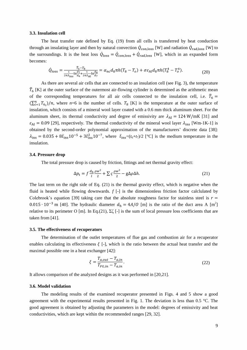
3.3. Insulation cell
The heat transfer rate defined by Eq. (19) from all cells is transferred by heat conduction
through an insulating layer and then by natural convection [W] and radiation [W] to
the surroundings. It is the heat loss [W], which in an expanded form
becomes:
. (20)
As there are several air cells that are connected to an insulation cell (see Fig. 3), the temperature
[K] at the outer surface of the outermost air-flowing cylinder is determined as the arithmetic mean
of the corresponding temperatures for all air cells connected to the insulation cell, i.e.
, where n=6 is the number of cells. [K] is the temperature at the outer surface of
insulation, which consists of a mineral wool layer coated with a 0.6 mm thick aluminum sheet. For the
aluminum sheet, its thermal conductivity and degree of emissivity are [31] and
[29], respectively. The thermal conductivity of the mineral wool layer [Wm-1K-1] is
obtained by the second-order polynomial approximation of the manufacturers’ discrete data [38]:
, where =(t6+t7)/2 [°C] is the medium temperature in the
insulation.
3.4. Pressure drop
The total pressure drop is caused by friction, fittings and net thermal gravity effect:
. (21)
The last term on the right side of Eq. (21) is the thermal gravity effect, which is negative when the
fluid is heated while flowing downwards. f [-] is the dimensionless friction factor calclulated by
Colebrook’s equation [39] taking care that the absolute roughness factor for stainless steel is
[40]. The hydraulic diameter [m] is the ratio of the duct area A [m2]
relative to its perimeter O [m]. In Eq.(21), Σζ [-] is the sum of local pressure loss coefficients that are
taken from [41].
3.5. The effectiveness of recuperators
The determination of the outlet temperatures of flue gas and combustion air for a recuperator
enables calculating its effectiveness [-], which is the ratio between the actual heat transfer and the
maximal possible one in a heat exchanger [42]:
(22)
It allows comparison of the analyzed designs as it was performed in [20,21].
3.6. Model validation
The modeling results of the examined recuperator presented in Figs. 4 and 5 show a good
agreement with the experimental results presented in Fig. 1. The deviation is less than 0.5 °C. The
good agreement is obtained by adjusting the parameters in the model: degrees of emissivity and heat
conductivities, which are kept within the recommended ranges [29, 32].
10
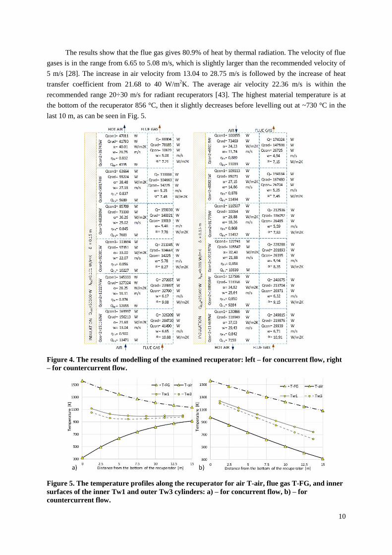
The results show that the flue gas gives 80.9% of heat by thermal radiation. The velocity of flue
gases is in the range from 6.65 to 5.08 m/s, which is slightly larger than the recommended velocity of
5 m/s [28]. The increase in air velocity from 13.04 to 28.75 m/s is followed by the increase of heat
transfer coefficient from 21.68 to 40 W/m2K. The average air velocity 22.36 m/s is within the
recommended range 20÷30 m/s for radiant recuperators [43]. The highest material temperature is at
the bottom of the recuperator 856 °C, then it slightly decreases before levelling out at ~730 °C in the
last 10 m, as can be seen in Fig. 5.
Figure 4. The results of modelling of the examined recuperator: left – for concurrent flow, right
– for countercurrent flow.
Figure 5. The temperature profiles along the recuperator for air T-air, flue gas T-FG, and inner
surfaces of the inner Tw1 and outer Tw3 cylinders: a) – for concurrent flow, b) – for
countercurrent flow.
11
4. Results
If the air flow in the examined concurrent recuperator is reversed, a pure countercurrent radiant
heat exchanger would be obtained. In that case, a theoretical improvement would be achieved because
of a larger mean temperature difference. These differences are 591.2 °C and 674.3 °C for concurrent
and countercurrent flow arrangements, respectively. These can be seen in Figs. 4 and 5. Table 1 shows
that the power of the recuperator would increase by 10.47%, which means that the air preheating
temperature would rise together with the effectiveness, whereas the heat loss would decrease if the
existing insulation is kept. Even the total pressure drop would be smaller for countercurrent flow due
to the smaller average air velocity, see Tab. 1 and Fig. 4, regardless of the negative thermal gravity
effect -108.2 Pa. This effect is positive 104.7 Pa for the concurrent recuperator.
Figure 5 and Tab. 1 show that the countercurrent recuperator has the maximal interface
temperature 966.4 °C, compared with 856 °C in the concurrent one. Oppositely, at the top of the
recuperator, where the construction is supported and where the material must withstand the highest
load, the countercurrent recuperator has a smaller interface temperature 477 °C, compared with 727 °C
for the existing construction. This means that different materials could be used for different segments
of the recuperator if they are mutually weldable.
Table 1. Physical properties of the examined recuperator and three specific designs that could be
obtained by its modification. For all four cases, d1=1.294 m and d3=1.372 m, d5=1.75 m for the
designs with double air annuluses. (material temperatures are for the innermost surface d1 for
all the designs)
Type of recuperator
Existing
concurrent
Countercurrent
Double air
annulus
countercurrent
Double air
annulus
concurrent
Total heat flow rate from flue gas [MW] 1.176 1.300 1.308 1.201
Heat loss to surroundings [kW] 30.3 25.5 27.4 32.2
Air outlet temperature [K] 915.2 977.7 980.5 926.3
Flue gas outlet temperature [K] 1134.6 1087.4 1084.4 1125.2
Effectiveness [-] 0.478 0.528 0.53 0.487
Max. material temperature [K] 1129.6 1239.5 1199.4 1085.5
Min. material temperature [K] 1000.4 749.9 782.1 977.8
Average material temperature [K] 1031 990.2 978.4 1016.2
Average air velocity (for both
passages in the double air annulus
designs)
[m/s] 22.36 20.3 2.48
23.28
2.42
25.72
Pressure drop [Pa] 4866 4043 4501 5593
Recommended average velocities
Flue gas [m/s] 3-5 [42] 3-5
Air [m/s] 20-30 [42] in the outer annulus <2
in the inner annulus 25-30
The addition of an extra cylinder over the existing recuperator makes a double annulus (double
pipe-in-pipe) system, which is shown in Fig. 2 e) and f). The larger the diameter of the outer annulus,
the larger the heat transfer in the recuperator, as can be seen in Fig. 6 a). However, for a constant
thickness of insulation with the increase of the diameter d5, the heat loss increases, too. This means
that for a constant thickness of insulation an optimal diameter of the outermost cylinder exists. For the
12
examined recuperator, the optimal diameter is in the range from 1.75 to 1.85 m. Table 1 shows
specific properties for the diameter d5=1.75. Due to the velocity profile, 25.94% of heat is transferred
to the air in the outer annulus compared with 71.96% in the inner one, although it has a smaller heat
transfer area. Compared with the countercurrent recuperator, the addition of an extra cylinder
decreases the maximal interface temperature, increases the total heat transfer rate and the
effectiveness, but also increases the pressure drop by 11.3% because of a larger average air velocity in
the inner annulus. In the outer annulus, the thermal gravity effect is larger than the total pressure drop:
35.9 Pa compared with 11.5 Pa.
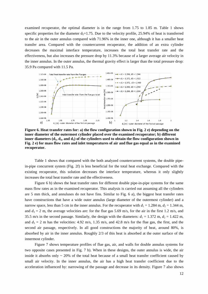
Figure 6. Heat transfer rates for: a) the flow configuration shown in Fig. 2 e) depending on the
inner diameter of the outermost cylinder placed over the examined recuperator; b) different
inner diameters (d1, d3, and d5) of the cylinders used to obtain the flow configuration shown in
Fig. 2 e) for mass flow rates and inlet temperatures of air and flue gas equal as in the examined
recuperator.
Table 1 shows that compared with the both analyzed countercurrent systems, the double pipe-
in-pipe concurrent system (Fig. 2f) is less beneficial for the total heat exchange. Compared with the
existing recuperator, this solution decreases the interface temperature, whereas it only slightly
increases the total heat transfer rate and the effectiveness.
Figure 6 b) shows the heat transfer rates for different double pipe-in-pipe systems for the same
mass flow rates as in the examined recuperator. This analysis is carried out assuming all the cylinders
are 5 mm thick, and annuluses do not have fins. Similar to Fig. 6 a), the biggest heat transfer rates
have constructions that have a wide outer annulus (large diameter of the outermost cylinder) and a
narrow space, less than 5 cm in the inner annulus. For the recuperator with d1 = 1.284 m, d2 = 1.344 m,
and d3 = 2 m, the average velocities are: for the flue gas 5.69 m/s, for the air in the first 1.2 m/s, and
35.5 m/s in the second passage. Similarly, the design with the diameters: d1 = 1.372 m, d2 = 1.422 m,
and d3 = 2 m has the velocities: 4.92 m/s, 1.35 m/s, and 42.8 m/s for the flue gas, the first, and the
second air passage, respectively. In all good constructions the majority of heat, around 80%, is
absorbed by air in the inner annulus. Roughly 2/3 of this heat is absorbed at the outer surface of the
innermost cylinder.
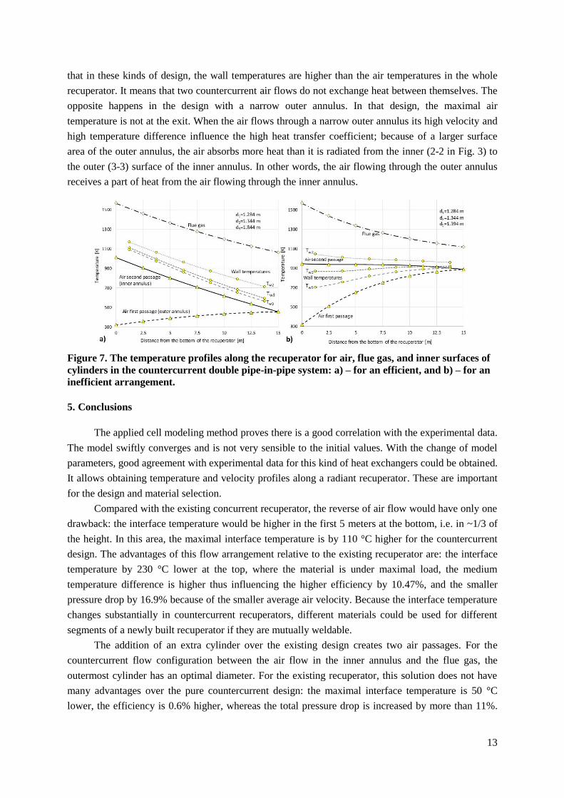
Figure 7 shows temperature profiles of flue gas, air, and walls for double annulus systems for
two opposite cases presented in Fig. 7 b). When in these designs, the outer annulus is wide, the air
inside it absorbs only ~ 20% of the total heat because of a small heat transfer coefficient caused by
small air velocity. In the inner annulus, the air has a high heat transfer coefficient due to the
acceleration influenced by: narrowing of the passage and decrease in its density. Figure 7 also shows
13
that in these kinds of design, the wall temperatures are higher than the air temperatures in the whole
recuperator. It means that two countercurrent air flows do not exchange heat between themselves. The
opposite happens in the design with a narrow outer annulus. In that design, the maximal air
temperature is not at the exit. When the air flows through a narrow outer annulus its high velocity and
high temperature difference influence the high heat transfer coefficient; because of a larger surface
area of the outer annulus, the air absorbs more heat than it is radiated from the inner (2-2 in Fig. 3) to
the outer (3-3) surface of the inner annulus. In other words, the air flowing through the outer annulus
receives a part of heat from the air flowing through the inner annulus.
Figure 7. The temperature profiles along the recuperator for air, flue gas, and inner surfaces of
cylinders in the countercurrent double pipe-in-pipe system: a) – for an efficient, and b) – for an
inefficient arrangement.
5. Conclusions
The applied cell modeling method proves there is a good correlation with the experimental data.
The model swiftly converges and is not very sensible to the initial values. With the change of model
parameters, good agreement with experimental data for this kind of heat exchangers could be obtained.
It allows obtaining temperature and velocity profiles along a radiant recuperator. These are important
for the design and material selection.
Compared with the existing concurrent recuperator, the reverse of air flow would have only one
drawback: the interface temperature would be higher in the first 5 meters at the bottom, i.e. in ~1/3 of
the height. In this area, the maximal interface temperature is by 110 °C higher for the countercurrent
design. The advantages of this flow arrangement relative to the existing recuperator are: the interface
temperature by 230 °C lower at the top, where the material is under maximal load, the medium
temperature difference is higher thus influencing the higher efficiency by 10.47%, and the smaller
pressure drop by 16.9% because of the smaller average air velocity. Because the interface temperature
changes substantially in countercurrent recuperators, different materials could be used for different
segments of a newly built recuperator if they are mutually weldable.
The addition of an extra cylinder over the existing design creates two air passages. For the
countercurrent flow configuration between the air flow in the inner annulus and the flue gas, the
outermost cylinder has an optimal diameter. For the existing recuperator, this solution does not have
many advantages over the pure countercurrent design: the maximal interface temperature is 50 °C
lower, the efficiency is 0.6% higher, whereas the total pressure drop is increased by more than 11%.
14
Compared with the existing recuperator, the double pipe-in-pipe system with the concurrent flow
should be used to slightly decrease the maximal interface temperature.
Both concurrent and countercurrent double pipe-in-pipe systems are only slightly more efficient
than pure concurrent and countercurrent recuperators, respectively. The advantage of these solutions
are smaller interface temperatures, whereas the disadvantages are their costs and pressure drops. To
implement these solutions, the average velocities should be: for flue gas around 5 m/s, for air in the
first passage less than 2 m/s, and for air in the second passage more than 25 m/s.
From the angle of view presented in this paper, the future work should include the optimization
of the flow configuration inside a radiant recuperator by combining the all four analyzed flow
configurations, stream splitting, varying the distances between cylinders along the recuperator as well
as the inclusion of devices that would improve convective and radiative heat transfer in a such design.
Acknowledgment
This work was conducted within the project EE 33027 supported by the Ministry of Education,
Science and Technological Development of the Republic of Serbia.
Nomenclature
cp - specific heat capacity, [Jkg-1K-1]
d - pipe diameter, [m]
EQ - exergy rate, [W]
- acceleration of gravity, 9.81 [ms-2]
p - pressure, [Pa]
T - temperature, [K]
w - velocity, [ms-1
]
Greek letters
- the change in,
- kinematic viscosity, [m2s-1]
ρ - density, [kgm-3]
Subscripts
a - air,
ann - annulus,
con - convection
cond - conduction
f - fin,
FG - fuel gas,
g - gas,
i - the i-th cell
ins - insulation
in - innlet
out - outlet
rad - thermal radiation
w - wall
1-8 - odd numbers designate inner, whereas
even numbers designate outer diameters of
cylinders according to their sizes (1 - the
smallest)
References
[1] http://www.lehigh.edu/imi/teched/GlassProcess/Lectures/Lecture03_Hubert_industglassmeltfurna
ces.pdf
[2] Dolianitis, I., et al., Waste heat recovery at the glass industry with the intervention of batch and
cullet preheating, Thermal Science, 00 (2016), pp. 79-79 , doi:10.2298/TSCI151127079D
[3] Prins, M.J. et al., Energy and exergy analysis of the oxidation and gasification of carbon, Energy,
(2005), 30(7), pp. 982-1002.
15
[4] Marnell, C.J., Development of the radiant recuperator, Proceedings, The first industrial energy
technology conference, Houston, TX, April 1979, pp. 607-619.
[5] Sharma, H., et al., A review of metallic radiation recuperators for thermal exhaust heat recovery,
Journal of Mechanical Science and Technology, 28 (2014), 3, pp. 1099-1111
[6] Shah, R.K., Sekulić, D.P., Fundamentals of Heat Exchanger Design, John Wiley and Sons Inc.,
New York, USA, 2003
[7] Luzzato, C., et al., A new concept composite heat exchanger to be applied in high-temperature
industrial processes, Applied Thermal Engineering, 17 (1997), 8-10, pp. 789-797
[8] https://www.nickelinstitute.org/~/Media/Files/TechnicalLiterature/High_TemperatureCharacteristi
csofStainlessSteel_9004_.pdf
[9] http://www.bssa.org.uk/cms/File/StainlessSteels_at_HighTemperatures_EN.pdf
[10] Sidhu, T. S., et al., Studies on the properties of HVOF coatings for higher temperature
applications, Material Science, 41 (2005), 6, pp. 805-823
[11] Collier, D.W., Single-ended recuperative radiant tube assembly and method, US Patent No.
4404099, (1983)
[12] Kenneth, G., et al., Radiant tube, EP No. 0403063 (1990)
[13] Azad, E., Aliahmad, H., Thermal performance of waste heat recuperator with heat pipes for
thermal power stations, Heat Recovery Systems and CHP, 9 (1989), 3, pp. 275-280
[14] Erinov, A.E., Semernin, A.M., Industrial furnaces with radiant tubes, Metallurgy, (1977), (in
Russian)
[15] Meder S.R., White A. J, Air-cooled radiation recuperator, US Patent No. 3446279 A, (1969)
[16] Shefsiek P.K., Cone C., Recuperator for gas-fired radiant tube furnace, US Patent No.
3859040, (1975)
[17] Stehlik, K., et al., Possibilities of intensifying heat transfer in heat exchangers for high
temperature applications, Chemical Engineering Transactions, 35 (2013), pp. 439-444
[18] Morimoto, P., et al., High performance recuperator with oblique wavy walls, ASME Journal
of Heat Transfer, 130 (2008), p. 10
[19] Jacobs, H., Metallic heat exchanger for high temperature gases, US Patent No. 2806677,
(1955)
[20] Sharma, H., et al., Performance analysis of metallic concentric tube recuperator in parallel
flow arrangement, International Journal of Heat and Mass Transfer, 55 (2012), pp. 7760-7771
[21] Sharma, H., et al., Performance model of metallic concentric tube recuperator with counter
flow arrangement, Heat and Mass Transfer, 46 (2010), pp. 295-304
[22] Kleiber, M., Joh, R., Calculation methods for thermophysical properties, in: VDI Gesellschaft,
VDI Heat Atlas, second ed., Springer, Heidelberg, 2010, pp. 121-152.
16
[23] Kleiber, M., Joh, R., Properties of selected important pure substances, in: VDI Gesellschaft,
VDI Heat Atlas, second ed., Springer, Heidelberg, 2010, pp. 153-299.
[24] Kleiber, M., Joh, R., Properties of pure fluid substances, in: VDI Gesellschaft, VDI Heat Atlas,
second ed., Springer, Heidelberg, 2010, pp. 301-417.
[25] Balmer, R.T. Thermodynamics, ST. Paul, New York, Los Angeles, San Francisco: West
Publishing Company, 1990.
[26] Awad, M.M., Approximate Expressions for the Logarithmic Mean Void Fraction, Thermal
Science, (2015), Vol. 19, No. 3, pp. 1135-1139.
[27] Gnielinski, V., Heat Transfer in Pipe Flow, in: VDI Gesellschaft, VDI Heat Atlas, second ed.,
Springer, Heidelberg, 2010, pp. 693-699.
[28] Vortmeyer, D., Kabelac, S, Gas Radiation: Radiation from Gas Mixtures, in: VDI
Gesellschaft, VDI Heat Atlas, second ed., Springer, Heidelberg, 2010, pp. 979-989.
[29] http://www-eng.lbl.gov/~dw/projects/DW4229_LHC_detector_analysis/calculations/
emissivity2.pdf
[30] Johnson, T.F., Bee´r, J.M., The zone method analysis of radiant heat transfer: A model for
luminous radiation. J Inst Fuel,(1973), 46, pp.301–309
[31] Richter, W., Goerner, K., Heat Radiation in Furnaces, in: VDI Gesellschaft, VDI Heat Atlas,
second ed., Springer, Heidelberg, 2010, pp. 1001-1012.
[32] Kozić, Dj., et al., Handbook for Thermodynamics (Priručnik za termodinamiku), Faculty of
Mechanical Engineering, Belgrade, 1995 (in Serbian).
[33] Gnielinski, V., Heat transfer in concentric annular and parallel plate ducts, in: VDI
Gesellschaft, VDI Heat Atlas, second ed., Springer, Heidelberg, 2010, pp. 947-959.
[34] Petukhov, B.S., Kirilov, V.V., On heat exchange at turbulant flow of liquids in pipes,
Teploenergetika, 4 (1958),pp. 63-68 (in Russian).
[35] Schmidt, K. G., Heat transfer to finned tubes, in: VDI Gesellschaft, VDI Heat Atlas, second
ed., Springer, Heidelberg, 2010, pp. 1273-1277.
[36] Kablec, S., Vortmeyer, D., Radiation of surfaces, in: VDI Gesellschaft, VDI Heat Atlas,
second ed., Springer, Heidelberg, 2010, pp. 947-959.
[37] Vortmeyer, D., Kablec, S.,View factors, in: VDI Gesellschaft, VDI Heat Atlas, second ed.,
Springer, Heidelberg, 2010, pp. 961-978.
[38] http://www.knaufinsulation.si/sites/si.knaufinsulation.net/files/KI-CENIK-vsi-izdelki.pdf
(in Slovenian)
[39] Mark, S., Owen, M.S., ASHRAE handbook fundamentals, American Society of Heating,
Refrigerating and Air-conditioning Engineers Inc., Atlanta, GA USA, 2009
[40] http://www.engineeringtoolbox.com/surface-roughness-ventilation-ducts-d_209.html
[41] Todorovic, B., Air Conditioning, SMEITS, Belgrade 2004 (in Serbian)

17
[42] http://www-
unix.ecs.umass.edu/~rlaurenc/Courses/che333/lectures/Heat%20Transfer/Lecture21.pdf
[43] Mitov, I., Comparative analysis of the energy efficiency of metal recuperators with a different
design, Journal of the University of Chemical Technology and Metallurgy: (2011), Vol. 46, No. 4,
pp. 427-432.


![BRP Guns · MG42 Recevier Front Recuperator Mount Hole/Slot 13.879 [352.54mm] R.11 [R2.81mm].221 [5.61mm].625 [15.88mm] Current location of front recuperator mount hole realtive to](https://img.pdfslide.net/doc/110x75/5ff543d35f7775336b5bf99a/brp-guns-mg42-recevier-front-recuperator-mount-holeslot-13879-35254mm-r11.jpg)