Embed Size (px)
Citation preview
PRIMERGY BX Blade Server Systems RemoteView Management BladeUser Interface Description
Edition November 2007
Comments… Suggestions… Corrections…The User Documentation Department would like toknow your opinion of this manual. Your feedback helpsus optimize our documentation to suit your individual needs.
Feel free to send us your comments by e-mail to [email protected].
Certified documentation according to DIN EN ISO 9001:2000To ensure a consistently high quality standard anduser-friendliness, this documentation was created tomeet the regulations of a quality management system which complies with the requirements of the standardDIN EN ISO 9001:2000.
cognitas. Gesellschaft für Technik-Dokumentation mbHwww.cognitas.de
Copyright and Trademarks
© c
ogni
tas.
Ge
sells
chft
für
Tech
nik
-Do
kum
ent
atio
n m
bH
200
7
Pfa
d: H
:\win
dow
s\_p
roje
kte
\AK
VM
\BX
_M
anag
em
ent\b
x-m
anb
lad
e.vo
r
Copyright © 2007 Fujitsu Siemens Computers GmbH.
All rights reserved.Delivery subject to availability; right of technical modifications reserved.
All hardware and software names used are trademarks of their respective manufacturers.
RemoteView Management Blade
Contents
1 Introduction . . . . . . . . . . . . . . . . . . . . . . . . . . . . 7
1.1 Notational Conventions . . . . . . . . . . . . . . . . . . . . . 8
1.2 Target Group . . . . . . . . . . . . . . . . . . . . . . . . . . . 8
2 PRIMERGY BX Blade Server Systems - Overview . . . . . . . 9
2.1 The Blade Server Concept . . . . . . . . . . . . . . . . . . . . 9
2.2 Blade Server Management . . . . . . . . . . . . . . . . . . . 102.2.1 Features of the RemoteView Management Blade . . . . . . . . 102.2.2 Redundancy of the RemoteView Management Blade . . . . . . 122.2.3 Console Redirection . . . . . . . . . . . . . . . . . . . . . . . 12
3 Telnet interface . . . . . . . . . . . . . . . . . . . . . . . . . 15
3.1 Entering the console mode . . . . . . . . . . . . . . . . . . 15
3.2 Console main menu . . . . . . . . . . . . . . . . . . . . . . 17
3.3 Management Agent . . . . . . . . . . . . . . . . . . . . . . . 193.3.1 Management Agent Information . . . . . . . . . . . . . . . . . 203.3.2 Management Blade . . . . . . . . . . . . . . . . . . . . . . . 243.3.3 System Information . . . . . . . . . . . . . . . . . . . . . . . 263.3.4 Server Blade . . . . . . . . . . . . . . . . . . . . . . . . . . . 283.3.4.1 Server Blade Control Information . . . . . . . . . . . . . . 283.3.4.2 Server Blade Information . . . . . . . . . . . . . . . . . . . 293.3.4.3 ServerBlade CPU . . . . . . . . . . . . . . . . . . . . . . 303.3.4.4 Server Blade Memory . . . . . . . . . . . . . . . . . . . . 313.3.4.5 Server Blade Voltage Table . . . . . . . . . . . . . . . . . 323.3.4.6 Server Blade Temperature . . . . . . . . . . . . . . . . . . 323.3.4.7 Server Blade NIC Information . . . . . . . . . . . . . . . . 343.3.4.8 Server Blade Watch Dog . . . . . . . . . . . . . . . . . . . 343.3.5 Switch Blade . . . . . . . . . . . . . . . . . . . . . . . . . . . 353.3.6 Username and Password . . . . . . . . . . . . . . . . . . . . 373.3.7 Blue Screen . . . . . . . . . . . . . . . . . . . . . . . . . . . 383.3.8 Event Log . . . . . . . . . . . . . . . . . . . . . . . . . . . . 383.3.8.1 Management Blade Event Log . . . . . . . . . . . . . . . . 39
RemoteView Management Blade
Contents
© c
ogn
itas.
Ges
ells
chft
für
Tech
nik-
Dok
um
enta
tion
mbH
200
7 P
fad
: H:\w
indo
ws\
_pr
oje
kte\
AK
VM
\BX
_Ma
nag
eme
nt\b
x-m
anbl
ade
.ivz
3.3.8.2 Server Blade Event Log . . . . . . . . . . . . . . . . . . . . 393.3.8.3 Server Blade Power On/Off Event Log Enable . . . . . . . . 403.3.8.4 Management Blade Wrap Around Event Log Enable . . . . . 403.3.9 Set System Default . . . . . . . . . . . . . . . . . . . . . . . . 413.3.10 Server Blade CMOS Backup/Restore . . . . . . . . . . . . . . 433.3.11 Switch Blade Configuration Backup/Restore . . . . . . . . . . . 453.3.12 Deployment Parameter . . . . . . . . . . . . . . . . . . . . . . 463.3.13 Power Consumption . . . . . . . . . . . . . . . . . . . . . . . 493.3.14 PPP and Modem Setting . . . . . . . . . . . . . . . . . . . . . 51
3.4 Emergency Management Port . . . . . . . . . . . . . . . . . 55
3.5 Console Redirection . . . . . . . . . . . . . . . . . . . . . . . 57
3.6 TFTP Update . . . . . . . . . . . . . . . . . . . . . . . . . . . 59
3.7 Logout . . . . . . . . . . . . . . . . . . . . . . . . . . . . . . 61
3.8 Reboot Management Blade . . . . . . . . . . . . . . . . . . . 61
3.9 System Information Dump . . . . . . . . . . . . . . . . . . . 62
4 Web user interface . . . . . . . . . . . . . . . . . . . . . . . . 63
4.1 Overview . . . . . . . . . . . . . . . . . . . . . . . . . . . . . 63
4.2 System Property . . . . . . . . . . . . . . . . . . . . . . . . . 664.2.1 System Event Log . . . . . . . . . . . . . . . . . . . . . . . . 664.2.1.1 Event Log . . . . . . . . . . . . . . . . . . . . . . . . . . . 674.2.1.2 Alarm handler . . . . . . . . . . . . . . . . . . . . . . . . . 674.2.2 Environment/Maintenance . . . . . . . . . . . . . . . . . . . . 694.2.2.1 Firmware Update . . . . . . . . . . . . . . . . . . . . . . . 694.2.2.2 Power Supply . . . . . . . . . . . . . . . . . . . . . . . . . 714.2.2.3 UPS . . . . . . . . . . . . . . . . . . . . . . . . . . . . . . 734.2.2.4 Chassis . . . . . . . . . . . . . . . . . . . . . . . . . . . . 744.2.2.5 Fans . . . . . . . . . . . . . . . . . . . . . . . . . . . . . . 754.2.2.6 Reset Management Blade . . . . . . . . . . . . . . . . . . . 754.2.3 LAN Interface . . . . . . . . . . . . . . . . . . . . . . . . . . . 764.2.3.1 Internet Protocol . . . . . . . . . . . . . . . . . . . . . . . . 764.2.3.2 Domain Name Server . . . . . . . . . . . . . . . . . . . . . 774.2.3.3 HTTP . . . . . . . . . . . . . . . . . . . . . . . . . . . . . 774.2.3.4 Telnet . . . . . . . . . . . . . . . . . . . . . . . . . . . . . 774.2.3.5 NTP . . . . . . . . . . . . . . . . . . . . . . . . . . . . . . 784.2.3.6 SSL . . . . . . . . . . . . . . . . . . . . . . . . . . . . . . 784.2.3.7 Duplex Mode . . . . . . . . . . . . . . . . . . . . . . . . . 78
RemoteView Management Blade
Contents
4.2.4 SNMP Interface . . . . . . . . . . . . . . . . . . . . . . . . . 794.2.4.1 SNMP Communities . . . . . . . . . . . . . . . . . . . . . 794.2.4.2 SNMP Trap Destination . . . . . . . . . . . . . . . . . . . 794.2.5 Console Redirection . . . . . . . . . . . . . . . . . . . . . . . 804.2.5.1 KVM Switch for Local . . . . . . . . . . . . . . . . . . . . 804.2.5.2 IP Filters for Telnet, HTTP and SNMP . . . . . . . . . . . . 804.2.6 System Information . . . . . . . . . . . . . . . . . . . . . . . 824.2.7 User Accounts . . . . . . . . . . . . . . . . . . . . . . . . . . 824.2.8 Deployment Table . . . . . . . . . . . . . . . . . . . . . . . . 834.2.9 PPP and Modem Setting . . . . . . . . . . . . . . . . . . . . 84
4.3 Management Blade . . . . . . . . . . . . . . . . . . . . . . . 85
4.4 Switch Blade . . . . . . . . . . . . . . . . . . . . . . . . . . 864.4.1 Switch Blade Info . . . . . . . . . . . . . . . . . . . . . . . . 864.4.2 Backup/Restore . . . . . . . . . . . . . . . . . . . . . . . . . 87
4.5 Adv. KVM Blade . . . . . . . . . . . . . . . . . . . . . . . . . 884.5.1 Adv. KVM Blade Info . . . . . . . . . . . . . . . . . . . . . . . 884.5.2 Adv. KVM Blade Configuration . . . . . . . . . . . . . . . . . . 894.5.3 Global Viewer . . . . . . . . . . . . . . . . . . . . . . . . . . 904.5.3.1 Requirements . . . . . . . . . . . . . . . . . . . . . . . . 904.5.3.2 Global Viewer Control Elements . . . . . . . . . . . . . . . 924.5.3.3 Global Viewer Operating Tasks . . . . . . . . . . . . . . . 954.5.4 Adv. KVM Blade Update . . . . . . . . . . . . . . . . . . . . . 97
4.6 Server Blade . . . . . . . . . . . . . . . . . . . . . . . . . . 984.6.1 Recovery . . . . . . . . . . . . . . . . . . . . . . . . . . . . . 994.6.1.1 Automatic Server Restart (ASR) . . . . . . . . . . . . . . . 994.6.1.2 Auto Configuration . . . . . . . . . . . . . . . . . . . . . . 994.6.1.3 Power Control . . . . . . . . . . . . . . . . . . . . . . . . 1004.6.1.4 Boot Option . . . . . . . . . . . . . . . . . . . . . . . . . 1004.6.2 Blade Info . . . . . . . . . . . . . . . . . . . . . . . . . . . . 1004.6.2.1 Blade Info . . . . . . . . . . . . . . . . . . . . . . . . . . 1004.6.2.2 Memory Module . . . . . . . . . . . . . . . . . . . . . . . 1014.6.2.3 Voltage . . . . . . . . . . . . . . . . . . . . . . . . . . . . 1024.6.2.4 Temperature . . . . . . . . . . . . . . . . . . . . . . . . . 102
Related publications . . . . . . . . . . . . . . . . . . . . . . . . . . . 103
Index . . . . . . . . . . . . . . . . . . . . . . . . . . . . . . . . . . . . 105

© c
ogn
itas.
Ges
ells
chft
für
Tech
nik-
Dok
um
enta
tion
mbH
200
7 P
fad
: H:\w
indo
ws\
_pr
oje
kte\
AK
VM
\BX
_Ma
nag
eme
nt\b
x-m
anbl
ade
.ivz
RemoteView Management Blade 7
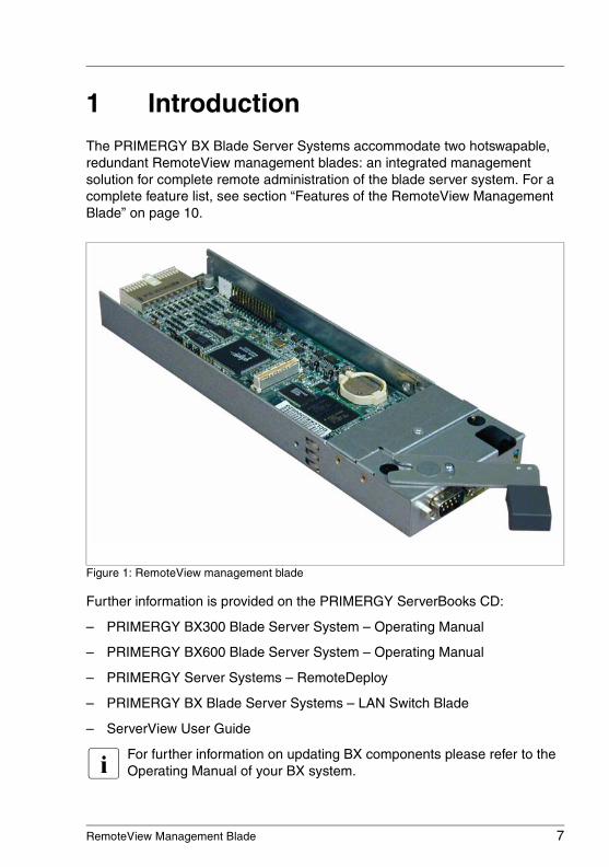
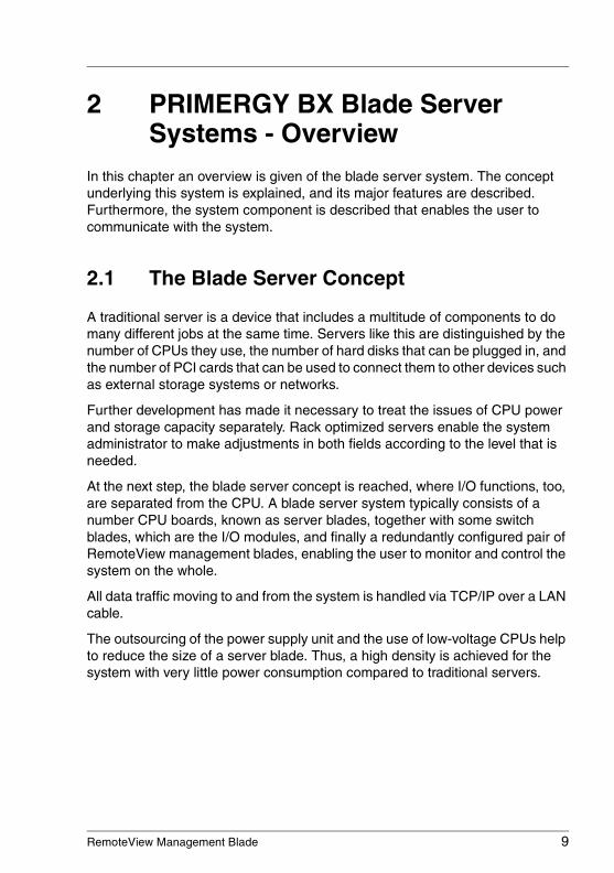
1 IntroductionThe PRIMERGY BX Blade Server Systems accommodate two hotswapable, redundant RemoteView management blades: an integrated management solution for complete remote administration of the blade server system. For a complete feature list, see section “Features of the RemoteView Management Blade” on page 10.
Figure 1: RemoteView management blade
Further information is provided on the PRIMERGY ServerBooks CD:
– PRIMERGY BX300 Blade Server System – Operating Manual
– PRIMERGY BX600 Blade Server System – Operating Manual
– PRIMERGY Server Systems – RemoteDeploy
– PRIMERGY BX Blade Server Systems – LAN Switch Blade
– ServerView User Guide
I For further information on updating BX components please refer to the Operating Manual of your BX system.
8 RemoteView Management Blade
Notational Conventions Introduction
© c
ogn
itas.
Ge
sells
chft
für
Tech
nik-
Dok
um
enta
tion
mbH
200
7 P
fad
: H:\w
indo
ws\
_pro
jekt
e\A
KV
M\B
X_M
anag
emen
t\bx-
man
bla
de.k
01
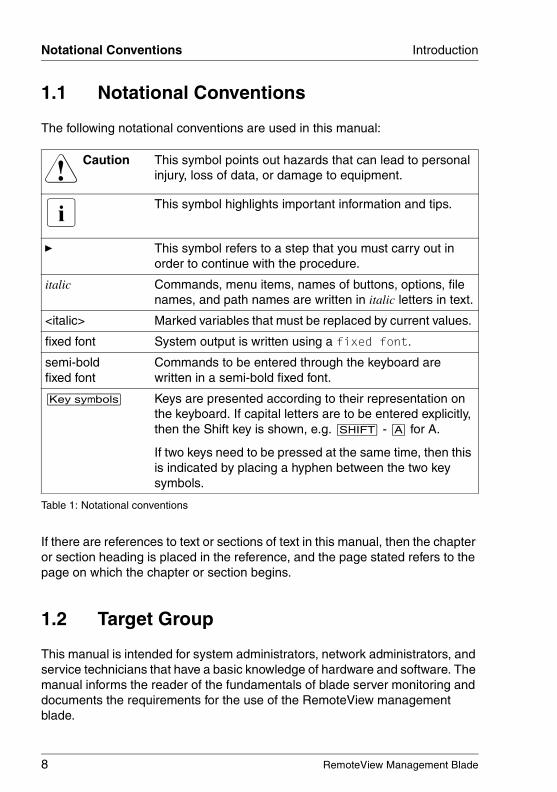
1.1 Notational Conventions
The following notational conventions are used in this manual:
If there are references to text or sections of text in this manual, then the chapter or section heading is placed in the reference, and the page stated refers to the page on which the chapter or section begins.
1.2 Target Group
This manual is intended for system administrators, network administrators, and service technicians that have a basic knowledge of hardware and software. The manual informs the reader of the fundamentals of blade server monitoring and documents the requirements for the use of the RemoteView management blade.
V Caution This symbol points out hazards that can lead to personal injury, loss of data, or damage to equipment.
I This symbol highlights important information and tips.
Ê This symbol refers to a step that you must carry out in order to continue with the procedure.
italic Commands, menu items, names of buttons, options, file names, and path names are written in italic letters in text.
<italic> Marked variables that must be replaced by current values.
fixed font System output is written using a fixed font.
semi-bold fixed font
Commands to be entered through the keyboard are written in a semi-bold fixed font.
[Key symbols] Keys are presented according to their representation on the keyboard. If capital letters are to be entered explicitly, then the Shift key is shown, e.g. [SHIFT] - [A] for A.
If two keys need to be pressed at the same time, then this is indicated by placing a hyphen between the two key symbols.
Table 1: Notational conventions
RemoteView Management Blade 9
2 PRIMERGY BX Blade Server Systems - Overview
In this chapter an overview is given of the blade server system. The concept underlying this system is explained, and its major features are described. Furthermore, the system component is described that enables the user to communicate with the system.
2.1 The Blade Server Concept
A traditional server is a device that includes a multitude of components to do many different jobs at the same time. Servers like this are distinguished by the number of CPUs they use, the number of hard disks that can be plugged in, and the number of PCI cards that can be used to connect them to other devices such as external storage systems or networks.
Further development has made it necessary to treat the issues of CPU power and storage capacity separately. Rack optimized servers enable the system administrator to make adjustments in both fields according to the level that is needed.
At the next step, the blade server concept is reached, where I/O functions, too, are separated from the CPU. A blade server system typically consists of a number CPU boards, known as server blades, together with some switch blades, which are the I/O modules, and finally a redundantly configured pair of RemoteView management blades, enabling the user to monitor and control the system on the whole.
All data traffic moving to and from the system is handled via TCP/IP over a LAN cable.
The outsourcing of the power supply unit and the use of low-voltage CPUs help to reduce the size of a server blade. Thus, a high density is achieved for the system with very little power consumption compared to traditional servers.
10 RemoteView Management Blade
Blade Server Management BX Blade Server System Overview
© c
ogn
itas.
Ge
sells
chft
für
Tech
nik-
Dok
um
enta
tion
mbH
200
7 P
fad
: H:\w
indo
ws\
_pro
jekt
e\A
KV
M\B
X_M
anag
emen
t\bx-
man
bla
de.k
02
2.2 Blade Server Management
When performing administrative tasks for the blade server system, the user relies on functions provided by a system component called the RemoteView management blade. There are two RemoteView management blades in a blade server system, in order to ensure redundancy.
The user gets access to the functions provided by the RemoteView management blade, either via a web user interface, or via a console menu using the Telnet protocol. Both ways of communication are described in more detail in the next two chapters of this manual (see chapter “Telnet interface” and chapter “Web user interface”).
2.2.1 Features of the RemoteView Management Blade
Within the blade server system the RemoteView management blade is equipped with a number of features, which are described in this section.
Controller
The RemoteView management blade is equipped with a Qlogic Zircon V2 controller.
Supported programs
The RemoteView management blade is compliant with IPMI (Internet Protocol Multicast Iniative) 1.0. It supports schemes like FRU (Field replaceable Units), SEL (System Event Log), and SDR (Sensor Data Records). It also allows the configuration of a watchdog timer.
Communication with the server blades
The RemoteView management blade communicates with the server blades via an I2C bus. An IPMB interface is provided to support the user, when performing hardware monitoring tasks for the server blades.
Communication with the switch blades
To enable communication with the switch blades, a CLI interface is provided. It allows to configure settings of the switch blades, such as the IP address, the IP mask, or the IP gateway address.
RemoteView Management Blade 11
BX Blade Server System Overview Blade Server Management
Hardware monitoring
The hardware monitoring functions provided by the RemoteView management blade include:
– Monitoring voltage and temperature of each server blade via the IPMB interface
– Monitoring the status of the system fans
– Monitoring intrusion into the system fans, i. e. if they have been opened, and other impacts on air flow conditions
– Setting the the system fans to an optimum speed
– Monitoring the status ot the power supply modules
– Monitoring the temperature of the switch blades via the I2C bus
Event repository
To store messages on events that occur in the system environment, the RemoteView management blade is equipped with an event repository, providing a 16 KB access EEPROM.
Auto configuration
The management function auto configuration is used to back up system param-eters to a ROM, which is located on the management blade. It also provides the possibility to restore these paramters if required. This reduces the risk if system configuration data have been corrupted or lost.
SSL (Secure Socket Layer)
The Manager Blade provides SSL for network data privacy for Telnet as well as for HTTP connections.
12 RemoteView Management Blade
Blade Server Management BX Blade Server System Overview
© c
ogn
itas.
Ge
sells
chft
für
Tech
nik-
Dok
um
enta
tion
mbH
200
7 P
fad
: H:\w
indo
ws\
_pro
jekt
e\A
KV
M\B
X_M
anag
emen
t\bx-
man
bla
de.k
02
2.2.2 Redundancy of the RemoteView Management Blade
Of the two RemoteView management blades within the blade server system, one will take over the role of the master, who is in charge of the server management, while the other one will remain in a standby status as a redundant component. The two components have the same IP address, but their MAC adresses differ from each other.
When the system is powered up, it depends on which of the two RemoteView management blade first outputs a heartbeat. This is then the one that will be the master.
The master blade and the redundant blade communicate symmetrically with each other via a TX/RX serial interface. As soon as the master fails to work properly, for instance, when unplugged by the system administrator, the standby component will take over control of the server management.
Fail-over scenario
When the redundant RemoteView management blade takes over control from the master, it will behave according to the following scenario:
– Issue an ICMP broadcast ping to update the ARP table and switch the IP filtering table, in order to adjust them with regard to the new MAC address
– Define a proprietary protocol in L2, which is used for remote communication
If communication between master and redundant component via the serial interface has broken down, these components can continue to communicate by sending IP broadcast packages, using the MAC addresses.
2.2.3 Console Redirection
When using the console redirection feature, the management of the blade server system may be executed in remote control mode. To support this mode, the RemoteView management blade acts as the console redirection agent.
The KVM (Keyboard/Video/Mouse) input is captured and sent to the RemoteView management blade. The RemoteView management blade will in turn send this input to a server blade, where the appropriate actions will be executed.
RemoteView Management Blade 13
BX Blade Server System Overview Blade Server Management
With the adv. KVM blade, advanced server management functions are available, such as graphic mode console redirection and remote USB CD-ROM and floppy disk emulation (PRIMERGY BX600 only).

© c
ogn
itas.
Ge
sells
chft
für
Tech
nik-
Dok
um
enta
tion
mbH
200
7 P
fad
: H:\w
indo
ws\
_pro
jekt
e\A
KV
M\B
X_M
anag
emen
t\bx-
man
bla
de.k
02
RemoteView Management Blade 15
3 Telnet interfaceWithin the blade server system a console menu is provided for server management, using the Telnet protocol. A number of configuration activities can be performed via this menu, e. g. IP address configuration or hardware status monitoring. The menu is described in this chapter.
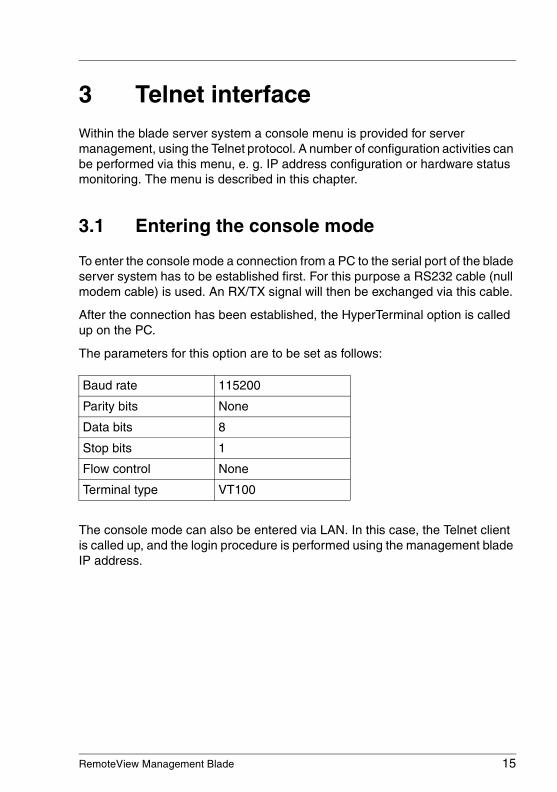
3.1 Entering the console mode
To enter the console mode a connection from a PC to the serial port of the blade server system has to be established first. For this purpose a RS232 cable (null modem cable) is used. An RX/TX signal will then be exchanged via this cable.
After the connection has been established, the HyperTerminal option is called up on the PC.
The parameters for this option are to be set as follows:
The console mode can also be entered via LAN. In this case, the Telnet client is called up, and the login procedure is performed using the management blade IP address.
Baud rate 115200
Parity bits None
Data bits 8
Stop bits 1
Flow control None
Terminal type VT100
16 RemoteView Management Blade
Entering the console mode Telnet interface
© c
ogn
itas.
Ge
sells
chft
für
Tech
nik-
Dok
um
enta
tion
mbH
200
7 P
fad
: H:\w
indo
ws\
_pro
jekt
e\A
KV
M\B
X_M
anag
emen
t\bx-
man
bla
de.k
03
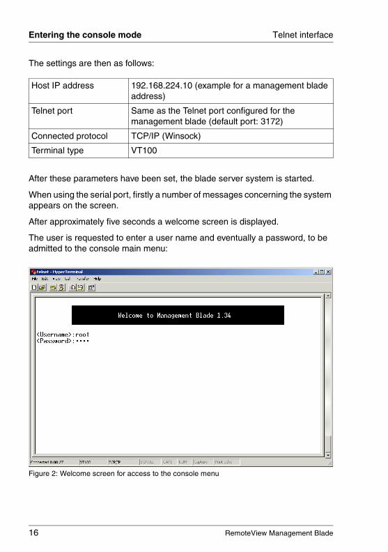
The settings are then as follows:
After these parameters have been set, the blade server system is started.
When using the serial port, firstly a number of messages concerning the system appears on the screen.
After approximately five seconds a welcome screen is displayed.
The user is requested to enter a user name and eventually a password, to be admitted to the console main menu:
Figure 2: Welcome screen for access to the console menu
Host IP address 192.168.224.10 (example for a management blade address)
Telnet port Same as the Telnet port configured for the management blade (default port: 3172)
Connected protocol TCP/IP (Winsock)
Terminal type VT100
RemoteView Management Blade 17
Telnet interface Console main menu
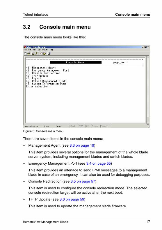
3.2 Console main menu
The console main menu looks like this:
Figure 3: Console main menu
There are seven items in the console main menu:
– Management Agent (see 3.3 on page 19)
This item provides several options for the management of the whole blade server system, including management blades and switch blades.
– Emergency Management Port (see 3.4 on page 55)
This item provides an interface to send IPMI messages to a management blade in case of an emergency. It can also be used for debugging purposes.
– Console Redirection (see 3.5 on page 57)
This item is used to configure the console redirection mode. The selected console redirection target will be active after the next boot.
– TFTP Update (see 3.6 on page 59)
This item is used to update the management blade firmware.
18 RemoteView Management Blade
Console main menu Telnet interface
© c
ogn
itas.
Ge
sells
chft
für
Tech
nik-
Dok
um
enta
tion
mbH
200
7 P
fad
: H:\w
indo
ws\
_pro
jekt
e\A
KV
M\B
X_M
anag
emen
t\bx-
man
bla
de.k
03
– Logout (see 3.7 on page 61)
This item is used to logout from the system.
– Reboot Management Blade (see 3.8 on page 61)
This item is used to perform a reboot of the system. The reboot is executed immediately.
– System Information Dump (see 3.9 on page 62)
This item is used to display consecutive lists of information.
The items of the console main menu are described in more detail in the following sections.
RemoteView Management Blade 19
Telnet interface Management Agent
3.3 Management Agent
The following items provided in the Management Agent sub-menu for server management:
– Management Agent Information (see 3.3.1 on page 20)
– Management Blade (see 3.3.2 on page 24)
– System Information (see 3.3.3 on page 26)
– Server Blade (see 3.3.4 on page 28)
– Switch Blade (see 3.3.5 on page 35)
– Username And Password (see 3.3.6 on page 37)
– Blue Screen (see 3.3.7 on page 38)
– Event Log (see 3.3.8 on page 38)
– Set System Default (see 3.3.9 on page 41)
– Server Blade CMOS Backup/Restore (see 3.3.10 on page 43)
– Switch Blade Configuration Backup/Restore (see 3.3.11 on page 45)
– Deployment Parameter (see 3.3.12 on page 46)
– Power Consumption (see 3.3.13 on page 49)
– PPP and Modem Setting (see 3.3.14 on page 51)
20 RemoteView Management Blade
Management Agent Telnet interface
© c
ogn
itas.
Ge
sells
chft
für
Tech
nik-
Dok
um
enta
tion
mbH
200
7 P
fad
: H:\w
indo
ws\
_pro
jekt
e\A
KV
M\B
X_M
anag
emen
t\bx-
man
bla
de.k
03
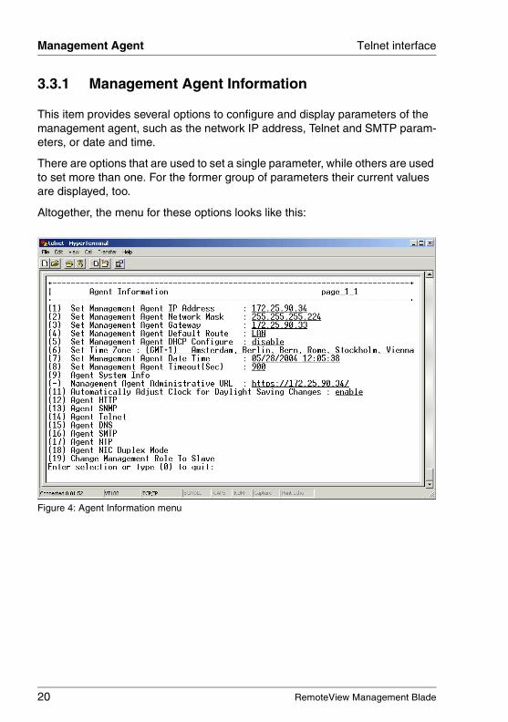
3.3.1 Management Agent Information
This item provides several options to configure and display parameters of the management agent, such as the network IP address, Telnet and SMTP param-eters, or date and time.
There are options that are used to set a single parameter, while others are used to set more than one. For the former group of parameters their current values are displayed, too.
Altogether, the menu for these options looks like this:
Figure 4: Agent Information menu
RemoteView Management Blade 21
Telnet interface Management Agent
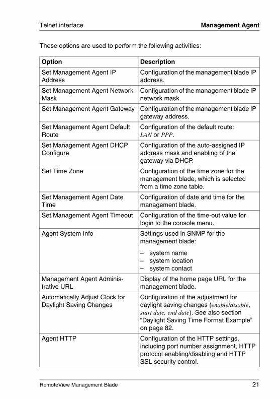
These options are used to perform the following activities:
Option Description
Set Management Agent IP Address
Configuration of the management blade IP address.
Set Management Agent Network Mask
Configuration of the management blade IP network mask.
Set Management Agent Gateway Configuration of the management blade IP gateway address.
Set Management Agent Default Route
Configuration of the default route: LAN or PPP.
Set Management Agent DHCP Configure
Configuration of the auto-assigned IP address mask and enabling of the gateway via DHCP.
Set Time Zone Configuration of the time zone for the management blade, which is selected from a time zone table.
Set Management Agent Date Time
Configuration of date and time for the management blade.
Set Management Agent Timeout Configuration of the time-out value for login to the console menu.
Agent System Info Settings used in SNMP for the management blade:
– system name– system location– system contact
Management Agent Adminis-trative URL
Display of the home page URL for the management blade.
Automatically Adjust Clock for Daylight Saving Changes
Configuration of the adjustment for daylight saving changes (enable/disable, start date, end date). See also section “Daylight Saving Time Format Example” on page 82.
Agent HTTP Configuration of the HTTP settings, including port number assignment, HTTP protocol enabling/disabling and HTTP SSL security control.
22 RemoteView Management Blade
Management Agent Telnet interface
© c
ogn
itas.
Ge
sells
chft
für
Tech
nik-
Dok
um
enta
tion
mbH
200
7 P
fad
: H:\w
indo
ws\
_pro
jekt
e\A
KV
M\B
X_M
anag
emen
t\bx-
man
bla
de.k
03
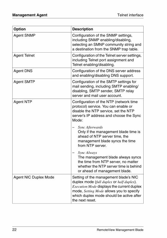
Agent SNMP Configuration of the SNMP settings, including SNMP enabling/disabling, selecting an SMNP community string and a destination from the SNMP trap table.
Agent Telnet Configuration of the Telnet server settings, including Telnet port assignment and Telnet enabling/disabling.
Agent DNS Configuration of the DNS server address and enabling/disabling DNS support.
Agent SMTP Configuration of the SMTP settings for mail sending, including SMTP enabling/ disabling, SMTP sender, SMTP relay server and mail user account.
Agent NTP Configuration of the NTP (network time protocol) service. You can enable or disable the NTP service, set the NTP server’s IP address and choose the Sync Mode:
– Sync AfterwardsOnly if the management blade time is ahead of NTP server time, the management blade syncs the time from NTP server.
– Sync AlwaysThe management blade always syncs the time from NTP server, no matter whether the NTP server time is behind or ahead of management blade.
Agent NIC Duplex Mode Setting of the management blade’s NIC duplex mode (full duplex or half duplex). Execution Mode displays the current duplex mode, Setting Mode allows you to specify which duplex mode should be active after the next reset.
Option Description
RemoteView Management Blade 23
Telnet interface Management Agent
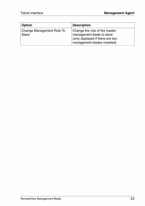
Change Management Role To Slave
Change the role of the master management blade to slave (only displayed if there are two management blades installed).
Option Description
24 RemoteView Management Blade
Management Agent Telnet interface
© c
ogn
itas.
Ge
sells
chft
für
Tech
nik-
Dok
um
enta
tion
mbH
200
7 P
fad
: H:\w
indo
ws\
_pro
jekt
e\A
KV
M\B
X_M
anag
emen
t\bx-
man
bla
de.k
03
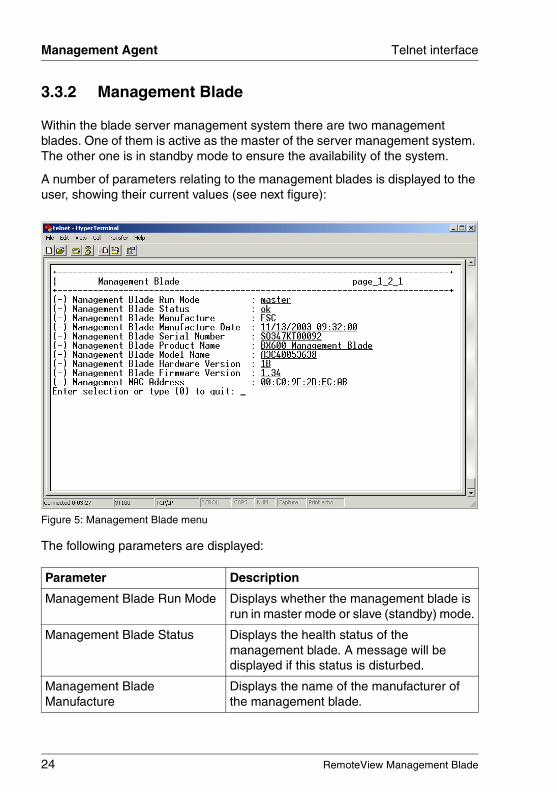
3.3.2 Management Blade
Within the blade server management system there are two management blades. One of them is active as the master of the server management system. The other one is in standby mode to ensure the availability of the system.
A number of parameters relating to the management blades is displayed to the user, showing their current values (see next figure):
Figure 5: Management Blade menu
The following parameters are displayed:
Parameter Description
Management Blade Run Mode Displays whether the management blade is run in master mode or slave (standby) mode.
Management Blade Status Displays the health status of the management blade. A message will be displayed if this status is disturbed.
Management Blade Manufacture
Displays the name of the manufacturer of the management blade.
RemoteView Management Blade 25
Telnet interface Management Agent
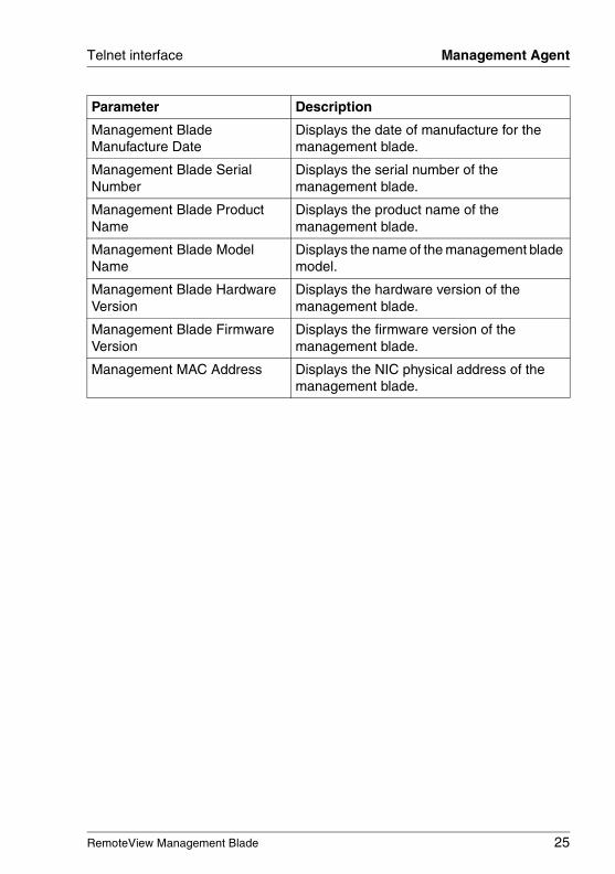
Management Blade Manufacture Date
Displays the date of manufacture for the management blade.
Management Blade Serial Number
Displays the serial number of the management blade.
Management Blade Product Name
Displays the product name of the management blade.
Management Blade Model Name
Displays the name of the management blade model.
Management Blade Hardware Version
Displays the hardware version of the management blade.
Management Blade Firmware Version
Displays the firmware version of the management blade.
Management MAC Address Displays the NIC physical address of the management blade.
Parameter Description
26 RemoteView Management Blade
Management Agent Telnet interface
© c
ogn
itas.
Ge
sells
chft
für
Tech
nik-
Dok
um
enta
tion
mbH
200
7 P
fad
: H:\w
indo
ws\
_pro
jekt
e\A
KV
M\B
X_M
anag
emen
t\bx-
man
bla
de.k
03
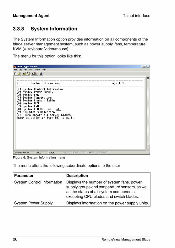
3.3.3 System Information
The System Information option provides information on all components of the blade server management system, such as power supply, fans, temperature, KVM (= keyboard/video/mouse).
The menu for this option looks like this:
Figure 6: System Information menu
The menu offers the following subordinate options to the user:
Parameter Description
System Control Information Displays the number of system fans, power supply groups and temperature sensors, as well as the status of all system components, excepting CPU blades and switch blades.
System Power Supply Displays information on the power supply units.
RemoteView Management Blade 27
Telnet interface Management Agent
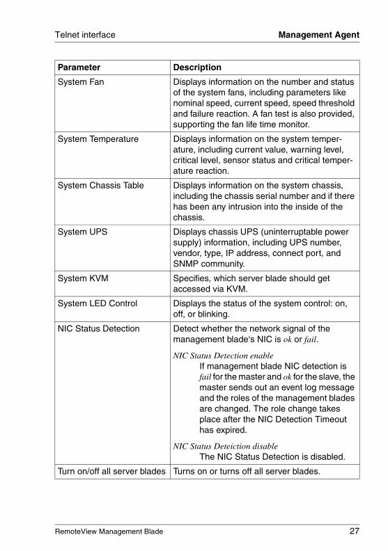
System Fan Displays information on the number and status of the system fans, including parameters like nominal speed, current speed, speed threshold and failure reaction. A fan test is also provided, supporting the fan life time monitor.
System Temperature Displays information on the system temper-ature, including current value, warning level, critical level, sensor status and critical temper-ature reaction.
System Chassis Table Displays information on the system chassis, including the chassis serial number and if there has been any intrusion into the inside of the chassis.
System UPS Displays chassis UPS (uninterruptable power supply) information, including UPS number, vendor, type, IP address, connect port, and SNMP community.
System KVM Specifies, which server blade should get accessed via KVM.
System LED Control Displays the status of the system control: on, off, or blinking.
NIC Status Detection Detect whether the network signal of the management blade‘s NIC is ok or fail.
NIC Status Detection enableIf management blade NIC detection is fail for the master and ok for the slave, the master sends out an event log message and the roles of the management blades are changed. The role change takes place after the NIC Detection Timeout has expired.
NIC Status Deteiction disableThe NIC Status Detection is disabled.
Turn on/off all server blades Turns on or turns off all server blades.
Parameter Description

28 RemoteView Management Blade
Management Agent Telnet interface
© c
ogn
itas.
Ge
sells
chft
für
Tech
nik-
Dok
um
enta
tion
mbH
200
7 P
fad
: H:\w
indo
ws\
_pro
jekt
e\A
KV
M\B
X_M
anag
emen
t\bx-
man
bla
de.k
03
3.3.4 Server Blade
The Server Blade option provides information on the server blades, i. e. infor-mation on CPUs, memory modules, voltage, temperature, CMOS configuration and watchdog timers.
The menu for this option looks like this:
Figure 7: Server Blade menu
3.3.4.1 Server Blade Control Information
This option enables the user to set the following parameters:
Parameter Description
Server Power Set server power:(1) on(2) off(3) power-cycle(4) reset(5) NMI(6) force off

RemoteView Management Blade 29
Telnet interface Management Agent
3.3.4.2 Server Blade Information
This option displays some information on the server blade parameters. The following parameters are included:
Set Server Maximum Restart Retries
Configuration of the maximum number for server restart retries. If the failure count reaches this value, the configured reaction will be executed.
Server LED Control Configuration of the LED control at the front of the blade server: blinking or off.
Server CPU Mode Configuration of the CPU mode: battery or perfor-mance mode. If the parameter is set to battery mode, this will save electric power.
Server Administrative URL Configuration of an URL address for the server.
Parameter Description
Server Blade Status Displays the server blade health status.
Server Blade Manufacture Displays server blade manufacture vendor infor-mation.
Server Blade Manufacture Date
Displays server blade manufacture date infor-mation.
Server Blade Serial Number
Displays server blade serial number information.
Server Blade Product Name
Displays server blade product name information.
Server Blade Product Version
Displays server blade product version information.
Server Blade Model Name Displays server blade model name information.
Server Blade Hardware Version
Displays server blade hardware version infor-mation.
Server Blade BIOS Version
Displays server blade BIOS version information.
Number of CPU Socket Displays how many CPU sockets are available on the server blade.
Parameter Description
30 RemoteView Management Blade
Management Agent Telnet interface
© c
ogn
itas.
Ge
sells
chft
für
Tech
nik-
Dok
um
enta
tion
mbH
200
7 P
fad
: H:\w
indo
ws\
_pro
jekt
e\A
KV
M\B
X_M
anag
emen
t\bx-
man
bla
de.k
03
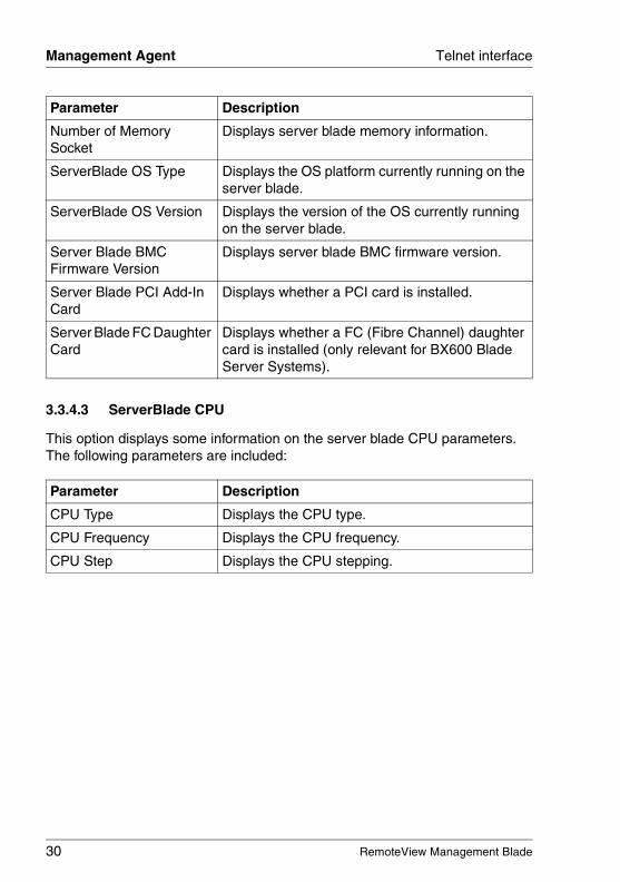
3.3.4.3 ServerBlade CPU
This option displays some information on the server blade CPU parameters. The following parameters are included:
Number of Memory Socket
Displays server blade memory information.
ServerBlade OS Type Displays the OS platform currently running on the server blade.
ServerBlade OS Version Displays the version of the OS currently running on the server blade.
Server Blade BMC Firmware Version
Displays server blade BMC firmware version.
Server Blade PCI Add-In Card
Displays whether a PCI card is installed.
Server Blade FC Daughter Card
Displays whether a FC (Fibre Channel) daughter card is installed (only relevant for BX600 Blade Server Systems).
Parameter Description
CPU Type Displays the CPU type.
CPU Frequency Displays the CPU frequency.
CPU Step Displays the CPU stepping.
Parameter Description
RemoteView Management Blade 31
Telnet interface Management Agent
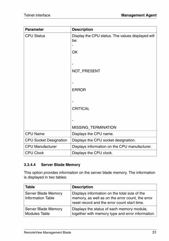
3.3.4.4 Server Blade Memory
This option provides information on the server blade memory. The information is displayed in two tables:
CPU Status Display the CPU status. The values displayed will be:-
OK
-
NOT_PRESENT
-
ERROR
-
CRITICAL
-
MISSING_TERMINATION
CPU Name Displays the CPU name.
CPU Socket Designation Displays the CPU socket designation.
CPU Manufacturer Displays information on the CPU manufacturer.
CPU Clock Displays the CPU clock.
Table Description
Server Blade Memory Information Table
Displays information on the total size of the memory, as well as on the error count, the error reset record and the error count start time.
Server Blade Memory Modules Table
Displays the status of each memory module, together with memory type and error information.
Parameter Description
32 RemoteView Management Blade
Management Agent Telnet interface
© c
ogn
itas.
Ge
sells
chft
für
Tech
nik-
Dok
um
enta
tion
mbH
200
7 P
fad
: H:\w
indo
ws\
_pro
jekt
e\A
KV
M\B
X_M
anag
emen
t\bx-
man
bla
de.k
03
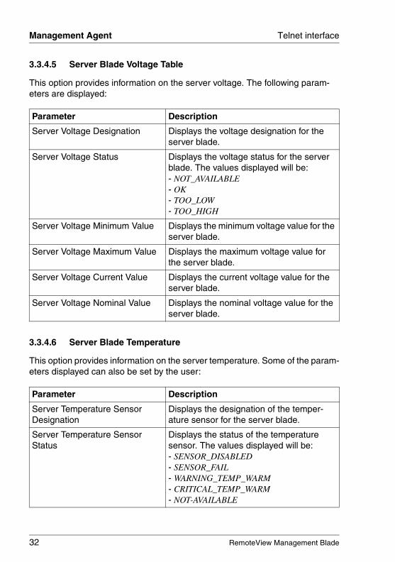
3.3.4.5 Server Blade Voltage Table
This option provides information on the server voltage. The following param-eters are displayed:
3.3.4.6 Server Blade Temperature
This option provides information on the server temperature. Some of the param-eters displayed can also be set by the user:
Parameter Description
Server Voltage Designation Displays the voltage designation for the server blade.
Server Voltage Status Displays the voltage status for the server blade. The values displayed will be: - NOT_AVAILABLE- OK- TOO_LOW- TOO_HIGH
Server Voltage Minimum Value Displays the minimum voltage value for the server blade.
Server Voltage Maximum Value Displays the maximum voltage value for the server blade.
Server Voltage Current Value Displays the current voltage value for the server blade.
Server Voltage Nominal Value Displays the nominal voltage value for the server blade.
Parameter Description
Server Temperature Sensor Designation
Displays the designation of the temper-ature sensor for the server blade.
Server Temperature Sensor Status
Displays the status of the temperature sensor. The values displayed will be:- SENSOR_DISABLED- SENSOR_FAIL- WARNING_TEMP_WARM- CRITICAL_TEMP_WARM- NOT-AVAILABLE
RemoteView Management Blade 33
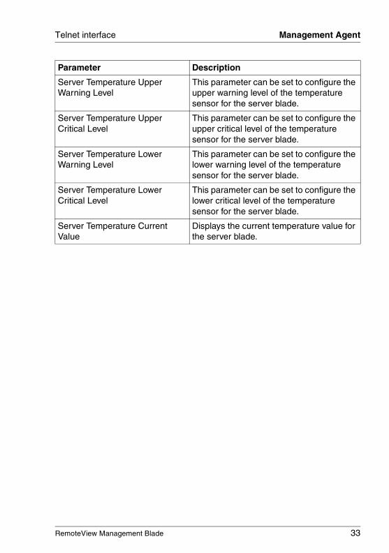
Telnet interface Management Agent
Server Temperature Upper Warning Level
This parameter can be set to configure the upper warning level of the temperature sensor for the server blade.
Server Temperature Upper Critical Level
This parameter can be set to configure the upper critical level of the temperature sensor for the server blade.
Server Temperature Lower Warning Level
This parameter can be set to configure the lower warning level of the temperature sensor for the server blade.
Server Temperature Lower Critical Level
This parameter can be set to configure the lower critical level of the temperature sensor for the server blade.
Server Temperature Current Value
Displays the current temperature value for the server blade.
Parameter Description
34 RemoteView Management Blade
Management Agent Telnet interface
© c
ogn
itas.
Ge
sells
chft
für
Tech
nik-
Dok
um
enta
tion
mbH
200
7 P
fad
: H:\w
indo
ws\
_pro
jekt
e\A
KV
M\B
X_M
anag
emen
t\bx-
man
bla
de.k
03
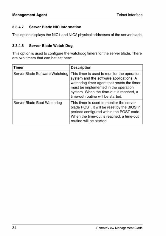
3.3.4.7 Server Blade NIC Information
This option displays the NIC1 and NIC2 physical addresses of the server blade.
3.3.4.8 Server Blade Watch Dog
This option is used to configure the watchdog timers for the server blade. There are two timers that can bet set here:
Timer Description
Server Blade Software Watchdog This timer is used to monitor the operation system and the software applications. A watchdog timer agent that resets the timer must be implemented in the operation system. When the time-out is reached, a time-out routine will be started.
Server Blade Boot Watchdog This timer is used to monitor the server blade POST. It will be reset by the BIOS in periods configured within the POST code. When the time-out is reached, a time-out routine will be started.
RemoteView Management Blade 35
Telnet interface Management Agent
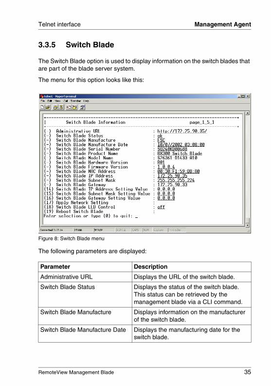
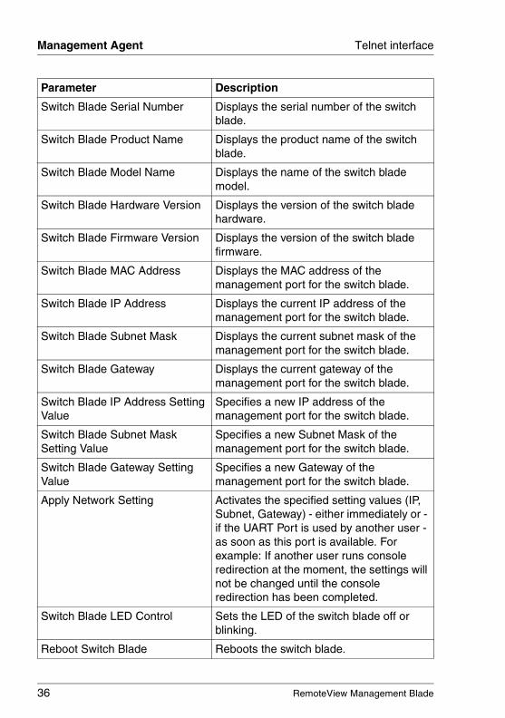
3.3.5 Switch Blade
The Switch Blade option is used to display information on the switch blades that are part of the blade server system.
The menu for this option looks like this:
Figure 8: Switch Blade menu
The following parameters are displayed:
Parameter Description
Administrative URL Displays the URL of the switch blade.
Switch Blade Status Displays the status of the switch blade. This status can be retrieved by the management blade via a CLI command.
Switch Blade Manufacture Displays information on the manufacturer of the switch blade.
Switch Blade Manufacture Date Displays the manufacturing date for the switch blade.
36 RemoteView Management Blade
Management Agent Telnet interface
© c
ogn
itas.
Ge
sells
chft
für
Tech
nik-
Dok
um
enta
tion
mbH
200
7 P
fad
: H:\w
indo
ws\
_pro
jekt
e\A
KV
M\B
X_M
anag
emen
t\bx-
man
bla
de.k
03
Switch Blade Serial Number Displays the serial number of the switch blade.
Switch Blade Product Name Displays the product name of the switch blade.
Switch Blade Model Name Displays the name of the switch blade model.
Switch Blade Hardware Version Displays the version of the switch blade hardware.
Switch Blade Firmware Version Displays the version of the switch blade firmware.
Switch Blade MAC Address Displays the MAC address of the management port for the switch blade.
Switch Blade IP Address Displays the current IP address of the management port for the switch blade.
Switch Blade Subnet Mask Displays the current subnet mask of the management port for the switch blade.
Switch Blade Gateway Displays the current gateway of the management port for the switch blade.
Switch Blade IP Address Setting Value
Specifies a new IP address of the management port for the switch blade.
Switch Blade Subnet Mask Setting Value
Specifies a new Subnet Mask of the management port for the switch blade.
Switch Blade Gateway Setting Value
Specifies a new Gateway of the management port for the switch blade.
Apply Network Setting Activates the specified setting values (IP, Subnet, Gateway) - either immediately or - if the UART Port is used by another user - as soon as this port is available. For example: If another user runs console redirection at the moment, the settings will not be changed until the console redirection has been completed.
Switch Blade LED Control Sets the LED of the switch blade off or blinking.
Reboot Switch Blade Reboots the switch blade.
Parameter Description
RemoteView Management Blade 37
Telnet interface Management Agent
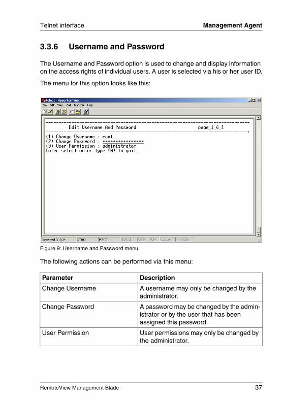
3.3.6 Username and Password
The Username and Password option is used to change and display information on the access rights of individual users. A user is selected via his or her user ID.
The menu for this option looks like this:
Figure 9: Username and Password menu
The following actions can be performed via this menu:
Parameter Description
Change Username A username may only be changed by the administrator.
Change Password A password may be changed by the admin-istrator or by the user that has been assigned this password.
User Permission User permissions may only be changed by the administrator.
38 RemoteView Management Blade
Management Agent Telnet interface
© c
ogn
itas.
Ge
sells
chft
für
Tech
nik-
Dok
um
enta
tion
mbH
200
7 P
fad
: H:\w
indo
ws\
_pro
jekt
e\A
KV
M\B
X_M
anag
emen
t\bx-
man
bla
de.k
03
3.3.7 Blue Screen
The Blue Screen option is available, if the operating system used supports the blue screen feature, as provided by UART (Windows 2000).
The option will then display which server blades are currently in blue screen status.
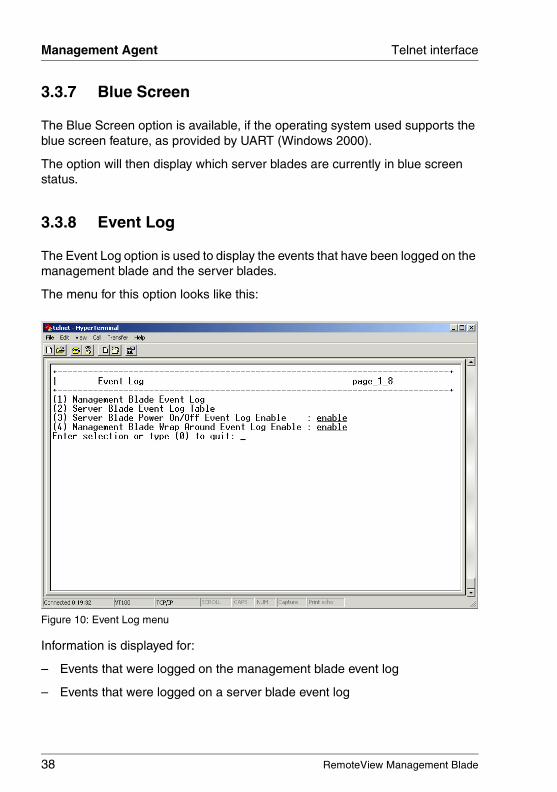
3.3.8 Event Log
The Event Log option is used to display the events that have been logged on the management blade and the server blades.
The menu for this option looks like this:
Figure 10: Event Log menu
Information is displayed for:
– Events that were logged on the management blade event log
– Events that were logged on a server blade event log
RemoteView Management Blade 39
Telnet interface Management Agent
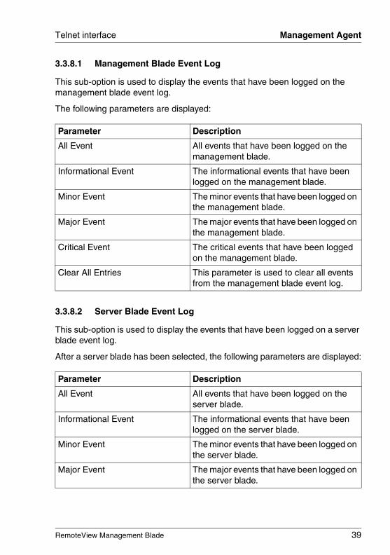
3.3.8.1 Management Blade Event Log
This sub-option is used to display the events that have been logged on the management blade event log.
The following parameters are displayed:
3.3.8.2 Server Blade Event Log
This sub-option is used to display the events that have been logged on a server blade event log.
After a server blade has been selected, the following parameters are displayed:
Parameter Description
All Event All events that have been logged on the management blade.
Informational Event The informational events that have been logged on the management blade.
Minor Event The minor events that have been logged on the management blade.
Major Event The major events that have been logged on the management blade.
Critical Event The critical events that have been logged on the management blade.
Clear All Entries This parameter is used to clear all events from the management blade event log.
Parameter Description
All Event All events that have been logged on the server blade.
Informational Event The informational events that have been logged on the server blade.
Minor Event The minor events that have been logged on the server blade.
Major Event The major events that have been logged on the server blade.
40 RemoteView Management Blade
Management Agent Telnet interface
© c
ogn
itas.
Ge
sells
chft
für
Tech
nik-
Dok
um
enta
tion
mbH
200
7 P
fad
: H:\w
indo
ws\
_pro
jekt
e\A
KV
M\B
X_M
anag
emen
t\bx-
man
bla
de.k
03
3.3.8.3 Server Blade Power On/Off Event Log Enable
This option is used to specify, whether power on/off events for the server blades should be listed in the event log.
3.3.8.4 Management Blade Wrap Around Event Log Enable
This option is used to specify, whether the wrap-around functionality for the event log should be used or not.
enableWhen the event log repository is full, new event log entries replace the old ones beginning with the first event log entry.
disableWhen the event log repository is full, no event log entries are written any longer.
Critical Event The critical events that have been logged on the server blade.
Clear All Entries This parameter is used to clear all events from a server blade event log.
Parameter Description
RemoteView Management Blade 41
Telnet interface Management Agent
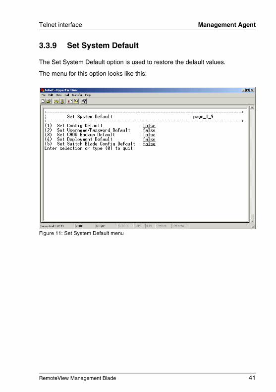
3.3.9 Set System Default
The Set System Default option is used to restore the default values.
The menu for this option looks like this:
Figure 11: Set System Default menu
42 RemoteView Management Blade
Management Agent Telnet interface
© c
ogn
itas.
Ge
sells
chft
für
Tech
nik-
Dok
um
enta
tion
mbH
200
7 P
fad
: H:\w
indo
ws\
_pro
jekt
e\A
KV
M\B
X_M
anag
emen
t\bx-
man
bla
de.k
03
The following parameters can be set:
Parameter Description
Set Config Default The configuration of the management blade is set to the default values.
V Please note that all configured values are lost and the management blade has to be configured newly after using this option.
Set Username/Password Default All configured user names with the exception of root are deleted. The password for the user root is set to the default (“root“).
Set CMOS Backup Default All switch blade configuration backups and all server blade BIOS backups are deleted.
Set Deployment Default The deployment parameters (see section “Deployment Parameter” on page 46) are set to the default values.
Set Switch Blade Config Default All switch blade configuration backups are deleted.
RemoteView Management Blade 43
Telnet interface Management Agent
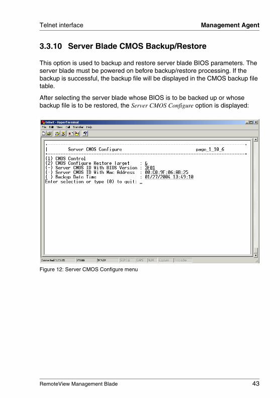
3.3.10 Server Blade CMOS Backup/Restore
This option is used to backup and restore server blade BIOS parameters. The server blade must be powered on before backup/restore processing. If the backup is successful, the backup file will be displayed in the CMOS backup file table.
After selecting the server blade whose BIOS is to be backed up or whose backup file is to be restored, the Server CMOS Configure option is displayed:
Figure 12: Server CMOS Configure menu
44 RemoteView Management Blade
Management Agent Telnet interface
© c
ogn
itas.
Ge
sells
chft
für
Tech
nik-
Dok
um
enta
tion
mbH
200
7 P
fad
: H:\w
indo
ws\
_pro
jekt
e\A
KV
M\B
X_M
anag
emen
t\bx-
man
bla
de.k
03
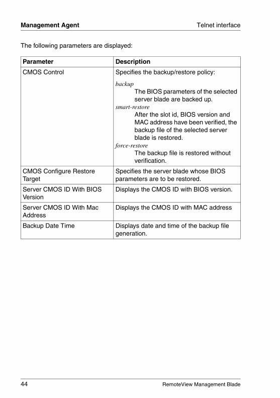
The following parameters are displayed:
Parameter Description
CMOS Control Specifies the backup/restore policy:
backupThe BIOS parameters of the selected server blade are backed up.
smart-restoreAfter the slot id, BIOS version and MAC address have been verified, the backup file of the selected server blade is restored.
force-restore The backup file is restored without verification.
CMOS Configure Restore Target
Specifies the server blade whose BIOS parameters are to be restored.
Server CMOS ID With BIOS Version
Displays the CMOS ID with BIOS version.
Server CMOS ID With Mac Address
Displays the CMOS ID with MAC address
Backup Date Time Displays date and time of the backup file generation.
RemoteView Management Blade 45
Telnet interface Management Agent
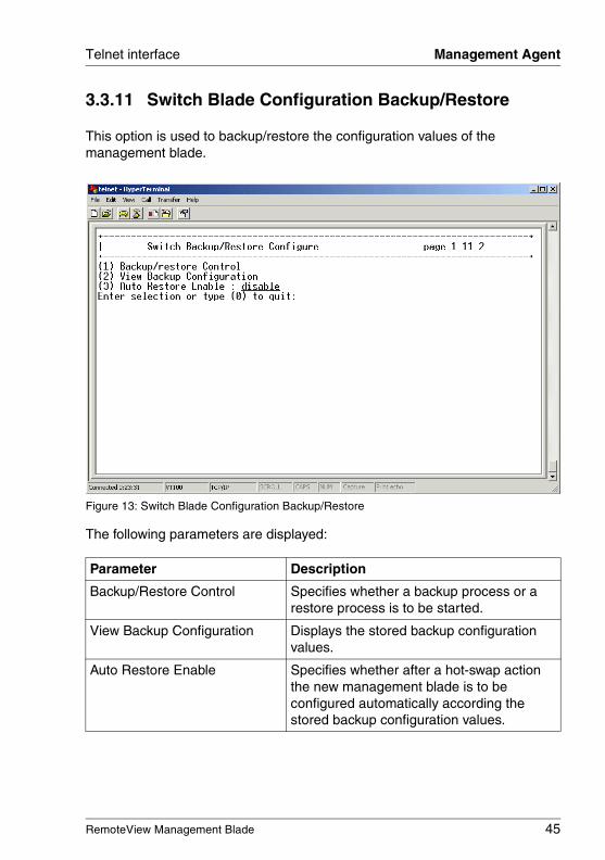
3.3.11 Switch Blade Configuration Backup/Restore
This option is used to backup/restore the configuration values of the management blade.
Figure 13: Switch Blade Configuration Backup/Restore
The following parameters are displayed:
Parameter Description
Backup/Restore Control Specifies whether a backup process or a restore process is to be started.
View Backup Configuration Displays the stored backup configuration values.
Auto Restore Enable Specifies whether after a hot-swap action the new management blade is to be configured automatically according the stored backup configuration values.
46 RemoteView Management Blade
Management Agent Telnet interface
© c
ogn
itas.
Ge
sells
chft
für
Tech
nik-
Dok
um
enta
tion
mbH
200
7 P
fad
: H:\w
indo
ws\
_pro
jekt
e\A
KV
M\B
X_M
anag
emen
t\bx-
man
bla
de.k
03
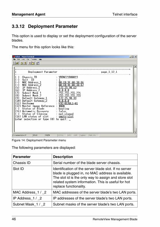
3.3.12 Deployment Parameter
This option is used to display or set the deployment configuration of the server blades.
The menu for this option looks like this:
Figure 14: Deployment Parameter menu
The following parameters are displayed:
Parameter Description
Chassis ID Serial number of the blade server chassis.
Slot ID Identification of the server blade slot. If no server blade is plugged in, no MAC address is available. The slot id is the only way to assign and store slot related system information. This is useful for hot replace functionality.
MAC Address_1 / _2 MAC addresses of the server blade’s two LAN ports.
IP Address_1 / _2 IP addresses of the server blade’s two LAN ports.
Subnet Mask_1 / _2 Subnet masks of the server blade’s two LAN ports.
RemoteView Management Blade 47
Telnet interface Management Agent
Default Gateway_1 / _2 Default gateways of the server blade’s two LAN ports.
Hostname Hostname for cloning purpose. Allows the clone agent to patch the right hostname into OS image during cloning process.
Master Image Reference
URL in UNC notification (but in ASCII) of the remote image file (with the extensions of *.img, *.cfg, *.txt):\\server-name\subpath\ img-name
Status of Blade Current status of the server blade. Possible values: !!bitte genau prüfen, die Werte sind in der Spec nicht explizit beschrieben und an der Oberfläche nicht testbar!!power-downstand bysystem boot failure bootingonline
Automatic Recovery Specifies whether after the hot-replacement of a server blade deployment activities should be started automatically.
falseAfter the hot-replacement of a server blade no automatic deployment activities should be started.
trueAfter the hot-replacement of a server blade RemoteDeploy is triggered to check in the server list, whether the old MAC address was assigned to a backup image. If so, the backup image is used for automatically cloning the new CPU blade (assumed the same HW is used). If there is no backup image, another check is made whether a master image is assigned to, and if so, this master image is used for cloning.
Parameter Description

48 RemoteView Management Blade
Management Agent Telnet interface
© c
ogn
itas.
Ge
sells
chft
für
Tech
nik-
Dok
um
enta
tion
mbH
200
7 P
fad
: H:\w
indo
ws\
_pro
jekt
e\A
KV
M\B
X_M
anag
emen
t\bx-
man
bla
de.k
03
Status of Cloning Specifies the status of the cloning process:
not-clonedThe server blade does not contain a valid configuration of an OS.
cloningThe cloning process is running. The status will switch to cloned when the process will have been completed.
clonedThe assigned image was successfully cloned.
LAN status of slot empty-slotWhen a new server blade is plugged in, the IP settings defined in the deployment parameter table are NOT used. You have to configure the IP settings manually. It is recommended to set the LAN Status of Slot to preset-slot afterwards.
preset-slotThe settings defined in the deployment parameter table are the reference for the LAN configuration. If a new or already installed blade is plugged in, these values are used for the installation/adaptation.
Parameter Description
RemoteView Management Blade 49
Telnet interface Management Agent
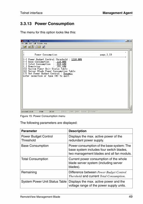
3.3.13 Power Consumption
The menu for this option looks like this:
Figure 15: Power Consumption menu
The following parameters are displayed:
Parameter Description
Power Budget Control Threshold
Displays the max. active power of the redundant power supply.
Base Consumption Power consumption of the base system: The base system includes four switch blades, two management blades and all fan moduls.
Total Consumption Current power consumption of the whole blade server system (including server blades).
Remaining Difference between Power Budget Control Thershold and current Total Consumption.
System Power Unit Status Table Displays the max. active power and the voltage range of the power supply units.
50 RemoteView Management Blade
Management Agent Telnet interface
© c
ogn
itas.
Ge
sells
chft
für
Tech
nik-
Dok
um
enta
tion
mbH
200
7 P
fad
: H:\w
indo
ws\
_pro
jekt
e\A
KV
M\B
X_M
anag
emen
t\bx-
man
bla
de.k
03
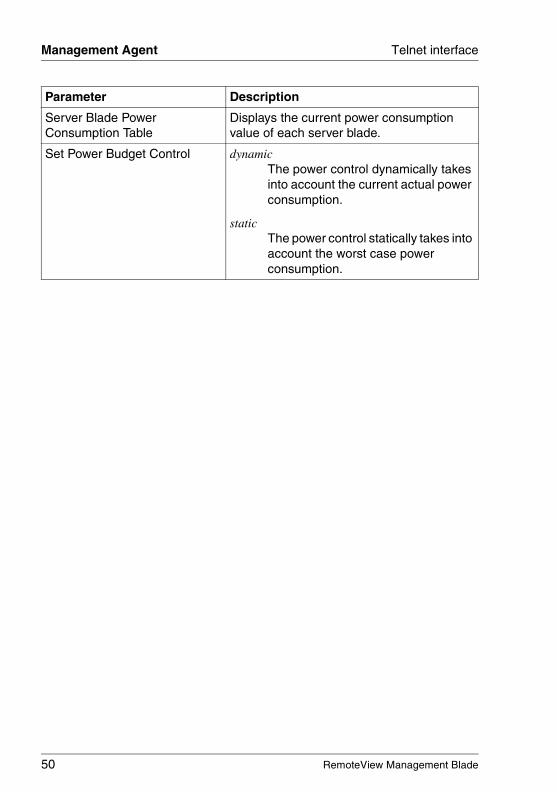
Server Blade Power Consumption Table
Displays the current power consumption value of each server blade.
Set Power Budget Control dynamicThe power control dynamically takes into account the current actual power consumption.
staticThe power control statically takes into account the worst case power consumption.
Parameter Description

RemoteView Management Blade 51
Telnet interface Management Agent
3.3.14 PPP and Modem Setting
The menu for this option looks like this:
Figure 16: PPP and Modem Setting menu
52 RemoteView Management Blade
Management Agent Telnet interface
© c
ogn
itas.
Ge
sells
chft
für
Tech
nik-
Dok
um
enta
tion
mbH
200
7 P
fad
: H:\w
indo
ws\
_pro
jekt
e\A
KV
M\B
X_M
anag
emen
t\bx-
man
bla
de.k
03
The following parameters are displayed:
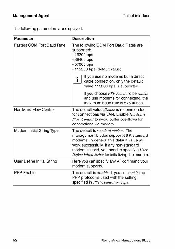
Parameter Description
Fastest COM Port Baud Rate The following COM Port Baud Rates are supported:- 19200 bps- 38400 bps- 57600 bps- 115200 bps (default value)
I If you use no modems but a direct cable connection, only the default value 115200 bps is supported.
If you choose PPP Enable to be enable and use modems for connecting, the maximum baud rate is 57600 bps.
Hardware Flow Control The default value disable is recommended for connections via LAN. Enable Hardware Flow Control to avoid buffer overflows for connections via modem.
Modem Initial String Type The default is standard modem. The management blades support 56 K standard modems. In general this default value will work successfully. If any non-standard modem is used, you need to specify a User Define Initial String for initializing the modem.
User Define Initial String Here you can specify any AT command your modem supports.
PPP Enable The default is disable. If you set enable the PPP protocol is used with the setting specified in PPP Connection Type.
RemoteView Management Blade 53
Telnet interface Management Agent
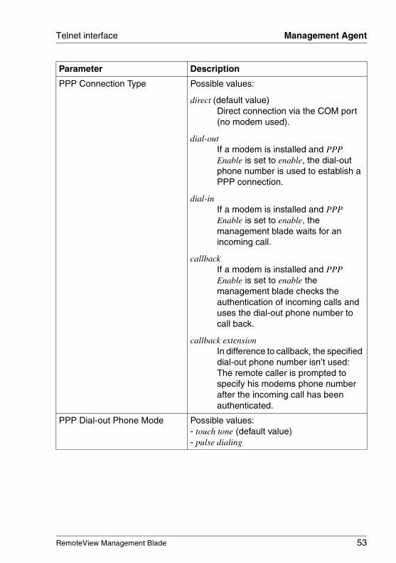
PPP Connection Type Possible values:
direct (default value)Direct connection via the COM port (no modem used).
dial-outIf a modem is installed and PPP Enable is set to enable, the dial-out phone number is used to establish a PPP connection.
dial-inIf a modem is installed and PPP Enable is set to enable, the management blade waits for an incoming call.
callbackIf a modem is installed and PPP Enable is set to enable the management blade checks the authentication of incoming calls and uses the dial-out phone number to call back.
callback extensionIn difference to callback, the specified dial-out phone number isn’t used: The remote caller is prompted to specify his modems phone number after the incoming call has been authenticated.
PPP Dial-out Phone Mode Possible values:- touch tone (default value)- pulse dialing
Parameter Description
54 RemoteView Management Blade
Management Agent Telnet interface
© c
ogn
itas.
Ge
sells
chft
für
Tech
nik-
Dok
um
enta
tion
mbH
200
7 P
fad
: H:\w
indo
ws\
_pro
jekt
e\A
KV
M\B
X_M
anag
emen
t\bx-
man
bla
de.k
03
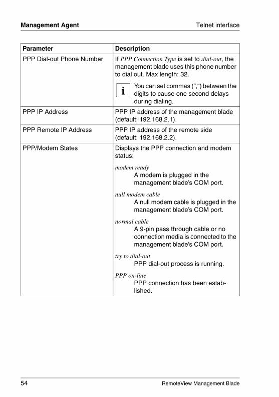
PPP Dial-out Phone Number If PPP Connection Type is set to dial-out, the management blade uses this phone number to dial out. Max length: 32.
I You can set commas (“,“) between the digits to cause one second delays during dialing.
PPP IP Address PPP IP address of the management blade (default: 192.168.2.1).
PPP Remote IP Address PPP IP address of the remote side (default: 192.168.2.2).
PPP/Modem States Displays the PPP connection and modem status:
modem readyA modem is plugged in the management blade’s COM port.
null modem cableA null modem cable is plugged in the management blade’s COM port.
normal cableA 9-pin pass through cable or no connection media is connected to the management blade’s COM port.
try to dial-outPPP dial-out process is running.
PPP on-linePPP connection has been estab-lished.
Parameter Description
RemoteView Management Blade 55
Telnet interface Emergency Management Port
3.4 Emergency Management Port
The Emergency Management Port (EMP) provides a basic range of remote server management with virtually no additional cost. It operates on top of the management blade firmware.
Commands for IPMI messages can be sent directly via the EMP agent.
The following facilities are provided:
– Server power up/down
– System reset
– Viewing of critical event logs stored in the non-volatile memory (NVRAM)
– System Event Log (SEL): logging of all critical server events, to be used for server monitoring and management
– Sensor Data Records (SDR): listing of all sensor fields programmed in the firmware of the Baseboard Management Controller (BMC), to be used for server monitoring and management
– Field Replaceable Units (FRU): listing of all replaceable components of the system by serial number
56 RemoteView Management Blade
Emergency Management Port Telnet interface
© c
ogn
itas.
Ge
sells
chft
für
Tech
nik-
Dok
um
enta
tion
mbH
200
7 P
fad
: H:\w
indo
ws\
_pro
jekt
e\A
KV
M\B
X_M
anag
emen
t\bx-
man
bla
de.k
03
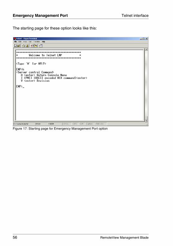
The starting page for these option looks like this:
Figure 17: Starting page for Emergency Management Port option
RemoteView Management Blade 57
Telnet interface Console Redirection
3.5 Console Redirection
There is one console port (serial port interface) within the blade server system. Console redirection can be configured for server blades or switch blades.
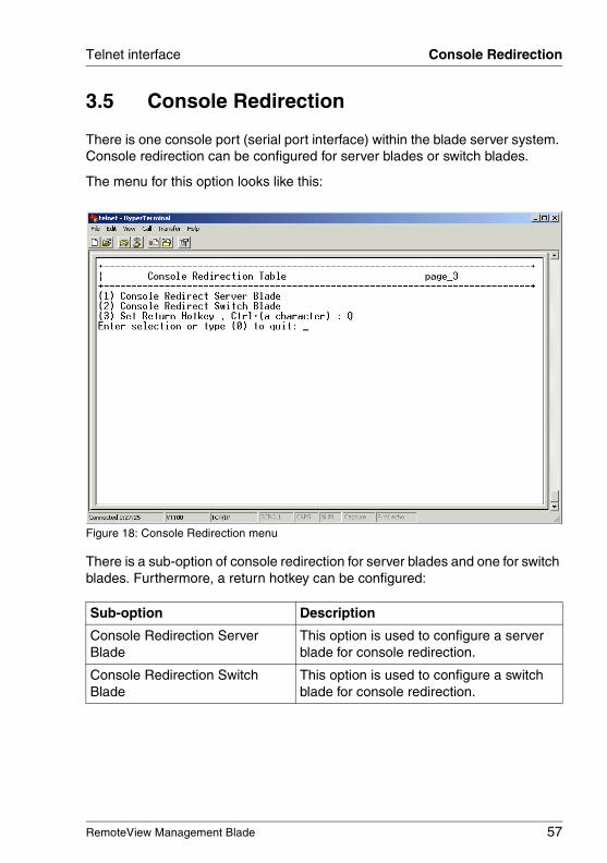
The menu for this option looks like this:
Figure 18: Console Redirection menu
There is a sub-option of console redirection for server blades and one for switch blades. Furthermore, a return hotkey can be configured:
Sub-option Description
Console Redirection Server Blade
This option is used to configure a server blade for console redirection.
Console Redirection Switch Blade
This option is used to configure a switch blade for console redirection.
58 RemoteView Management Blade
Console Redirection Telnet interface
© c
ogn
itas.
Ge
sells
chft
für
Tech
nik-
Dok
um
enta
tion
mbH
200
7 P
fad
: H:\w
indo
ws\
_pro
jekt
e\A
KV
M\B
X_M
anag
emen
t\bx-
man
bla
de.k
03
Set Return Hotkey This option is used to configure a return hotkey.
To do this, a character from A-Z is chosen, excluding M. The hotkey to exit console redirection and return to the previous mode is then Ctrl + the character that has been set here, e. g. Ctrl + R.
The default character used for the return hotkey is Q.
Sub-option Description
RemoteView Management Blade 59
Telnet interface TFTP Update
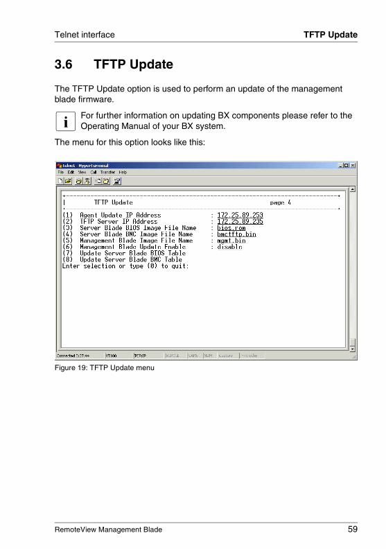
3.6 TFTP Update
The TFTP Update option is used to perform an update of the management blade firmware.
I For further information on updating BX components please refer to the Operating Manual of your BX system.
The menu for this option looks like this:
Figure 19: TFTP Update menu
60 RemoteView Management Blade
TFTP Update Telnet interface
© c
ogn
itas.
Ge
sells
chft
für
Tech
nik-
Dok
um
enta
tion
mbH
200
7 P
fad
: H:\w
indo
ws\
_pro
jekt
e\A
KV
M\B
X_M
anag
emen
t\bx-
man
bla
de.k
03
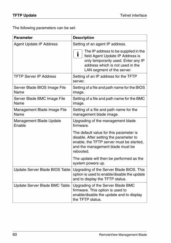
The following parameters can be set:
Parameter Description
Agent Update IP Address Setting of an agent IP address.
I The IP address to be supplied in the field Agent Update IP Address is only temporarily used. Enter any IP address which is not used in the LAN segment of the server.
TFTP Server IP Address Setting of an IP address for the TFTP server.
Server Blade BIOS Image File Name
Setting of a file and path name for the BIOS image.
Server Blade BMC Image File Name
Setting of a file and path name for the BMC image.
Management Blade Image File Name
Setting of a file and path name for the management blade image.
Management Blade Update Enable
Upgrading of the management blade firmware.
The default value for this parameter is disable. After setting the parameter to enable, the TFTP server must be started, and the management blade must be rebooted.
The update will then be performed as the system powers up.
Update Server Blade BIOS Table Upgrading of the Server Blade BIOS. This option is used to enable/disable the update and to display the TFTP status.
Update Server Blade BMC Table Upgrading of the Server Blade BMC firmware. This option is used to enable/disable the update and to display the TFTP status.
RemoteView Management Blade 61
Telnet interface Logout
3.7 Logout
This option is provided to perform a logout from the Telnet console menu.
3.8 Reboot Management Blade
This option is provided to perform the reboot of a management blade. The reboot is executed using a Zircon internal reset logic module.
© c
ogn
itas.
Ge
sells
chft
für
Tech
nik-
Dok
um
enta
tion
mbH
200
7 P
fad
: H:\w
indo
ws\
_pro
jekt
e\A
KV
M\B
X_M
anag
emen
t\bx-
man
bla
de.k
03
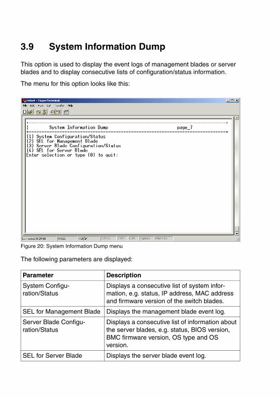
3.9 System Information Dump
This option is used to display the event logs of management blades or server blades and to display consecutive lists of configuration/status information.
The menu for this option looks like this:
Figure 20: System Information Dump menu
The following parameters are displayed:
Parameter Description
System Configu-ration/Status
Displays a consecutive list of system infor-mation, e.g. status, IP address, MAC address and firmware version of the switch blades.
SEL for Management Blade Displays the management blade event log.
Server Blade Configu-ration/Status
Displays a consecutive list of information about the server blades, e.g. status, BIOS version, BMC firmware version, OS type and OS version.
SEL for Server Blade Displays the server blade event log.
RemoteView Management Blade 63
4 Web user interfaceOn the web server an interactive and user-friendly web user interface, known as web console, is provided for server management. It does not depend on any special operating system for a platform. Login to this interface is made via the web browser.
The options of this interface are explained in this chapter.
4.1 Overview
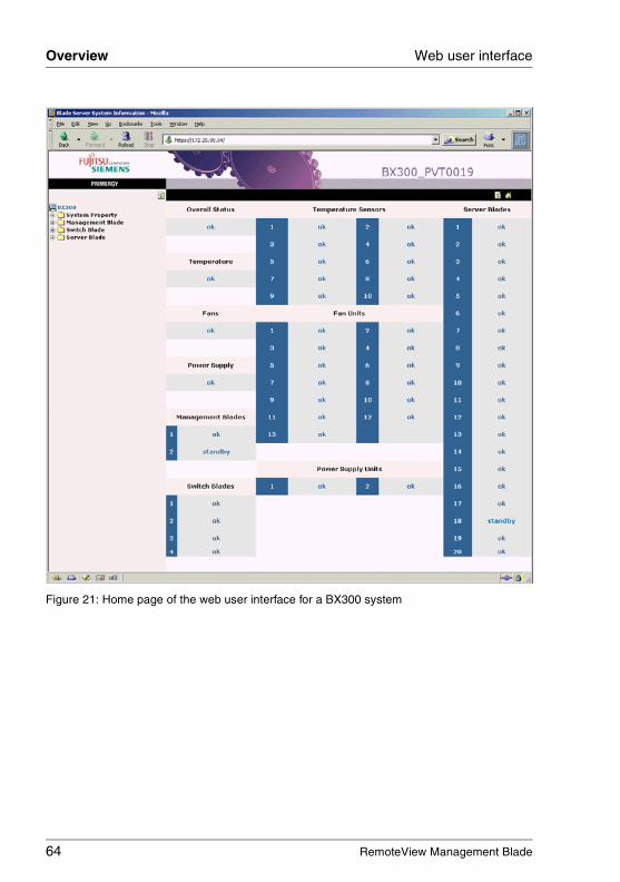
After login has been made successfully, a home page is displayed to the user, giving an overview over the system configuration, i.e. the installed components and their actual states. The navigation frame on the left side of the window shows options applying to the system properties, by which the system configu-ration may be modified, as well as options for working with the different kinds of blades that are embedded into the system.
Altogether, the options of the web user interface have been arranged into the following main groups:
– System Property (see 4.2 on page 66)
– Management Blade (see 4.3 on page 85)
– Switch Blade (see 4.4 on page 86)
– Adv. KVM Blade1 (see 4.5 on page 88)
– Server Blade (see 4.6 on page 98)
In the Server Blade and Switch Blade groups there is a sub-directory displayed for every blade. Thus, the user may see at a glance how many blades there are currently embedded in the system.
The figure next page shows the home page of the web user interface of the BX300, giving an overview over its options (the BX600 has some slightly modified hardware components):
1 PRIMERGY BX600 only
64 RemoteView Management Blade
Overview Web user interface
© c
ogn
itas.
Ge
sells
chft
für
Tech
nik-
Dok
um
enta
tion
mbH
200
7 P
fad
: H:\w
indo
ws\
_pro
jekt
e\A
KV
M\B
X_M
anag
emen
t\bx-
man
bla
de.k
04
Figure 21: Home page of the web user interface for a BX300 system
RemoteView Management Blade 65
Web user interface Overview
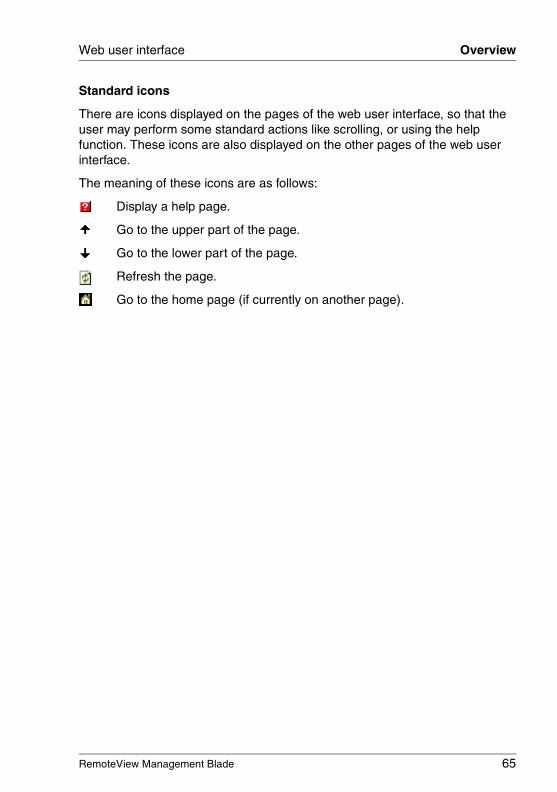
Standard icons
There are icons displayed on the pages of the web user interface, so that the user may perform some standard actions like scrolling, or using the help function. These icons are also displayed on the other pages of the web user interface.
The meaning of these icons are as follows:
Display a help page.
Go to the upper part of the page.
Go to the lower part of the page.
Refresh the page.
Go to the home page (if currently on another page).
66 RemoteView Management Blade
System Property Web user interface
© c
ogn
itas.
Ge
sells
chft
für
Tech
nik-
Dok
um
enta
tion
mbH
200
7 P
fad
: H:\w
indo
ws\
_pro
jekt
e\A
KV
M\B
X_M
anag
emen
t\bx-
man
bla
de.k
04
4.2 System Property
By working with the option System Property the user can apply changes to the system configuration.
The settings of the system configuration that can be modified by the user have been grouped into six fields. Corresponding to these are the following options:
– System Events Log (see 4.2.1 on page 66)
– Environment/Maintenance (see 4.2.2 on page 69)
– LAN Interface (see 4.2.3 on page 76)
– SNMP Interface (see 4.2.4 on page 79)
– Console Redirection (see 4.2.5 on page 80)
– System Information (see 4.2.6 on page 82)
– User Accounts (see 4.2.7 on page 82)
– Deployment Table (The parameters are very similar to those of the corre-sponding Telnet option, thus you can refer to the description in 3.3.12 on page 46).
– PPP and Modem Setting (The parameters are very similar to those of the corresponding Telnet option, thus you can refer to the description in 3.3.14 on page 51).
4.2.1 System Event Log
The System Event Log option provides information on events that happened on the system. Alarms can be configured for events in such a way that an e-mail is sent whenever an event of a certain kind occurs.
The option comprises two sub-options:
– Event Log
– Alarm Handler
RemoteView Management Blade 67
Web user interface System Property
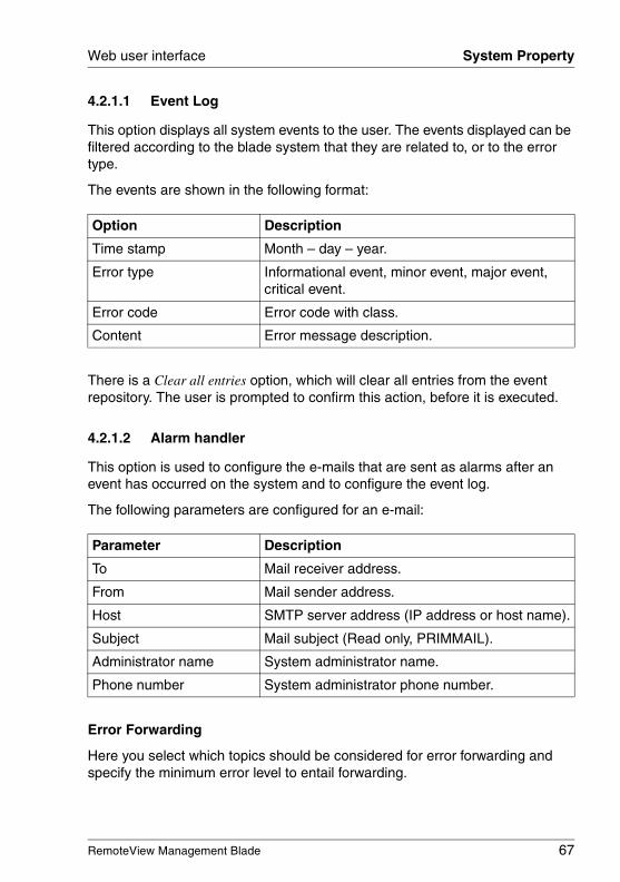
4.2.1.1 Event Log
This option displays all system events to the user. The events displayed can be filtered according to the blade system that they are related to, or to the error type.
The events are shown in the following format:
There is a Clear all entries option, which will clear all entries from the event repository. The user is prompted to confirm this action, before it is executed.
4.2.1.2 Alarm handler
This option is used to configure the e-mails that are sent as alarms after an event has occurred on the system and to configure the event log.
The following parameters are configured for an e-mail:
Error Forwarding
Here you select which topics should be considered for error forwarding and specify the minimum error level to entail forwarding.
Option Description
Time stamp Month – day – year.
Error type Informational event, minor event, major event, critical event.
Error code Error code with class.
Content Error message description.
Parameter Description
To Mail receiver address.
From Mail sender address.
Host SMTP server address (IP address or host name).
Subject Mail subject (Read only, PRIMMAIL).
Administrator name System administrator name.
Phone number System administrator phone number.
68 RemoteView Management Blade
System Property Web user interface
© c
ogn
itas.
Ge
sells
chft
für
Tech
nik-
Dok
um
enta
tion
mbH
200
7 P
fad
: H:\w
indo
ws\
_pro
jekt
e\A
KV
M\B
X_M
anag
emen
t\bx-
man
bla
de.k
04
Server Blade Power On/Off Event Log Enable
This option is used to specify, whether power on/off events for the server blades should be listed in the event log.
Management Blade Wrap Around Event Log Enable
This option is used to specify, whether the wrap-around functionality for the event log should be used.
enableWhen the event log repository is full, new event log entries replace the old ones beginning with the first event log entry.
disableWhen the event log repository is full, no event log entries are written any longer.

RemoteView Management Blade 69
Web user interface System Property
4.2.2 Environment/Maintenance
This option is used to adjust the settings of the environment modules. These modules monitor power supply, chassis and fans of the system. The system administrator can configure a reaction to be executed when a critical threshold value is reached for a module.
There are the following sub-options:
– Firmware Update
– Power Supply
– UPS
– Chassis
– Fans
– Reset Management Blade
4.2.2.1 Firmware Update
This option is used to perform firmware updates for the blade server system. The upgrades are performed via the TFTP service.
There are three different kinds of updates:
– Management blade
– Server blade BMC
– Server blade BIOS
I For further information on updating BX components please refer to the Operating Manual of your BX system.

70 RemoteView Management Blade
System Property Web user interface
© c
ogn
itas.
Ge
sells
chft
für
Tech
nik-
Dok
um
enta
tion
mbH
200
7 P
fad
: H:\w
indo
ws\
_pro
jekt
e\A
KV
M\B
X_M
anag
emen
t\bx-
man
bla
de.k
04
Management Blade BMC Update
To perform a management blade BMC update, the following parameters can be set:
Server Blade BMC Update
To perform a server blade BMC update, the following parameters can be set:
Select in the list on the right side of the window the server blades you want to be updated and click on the [ADD>>] button. They are moved into the update list on the right side. You can remove server blades from the update list by selecting them and clicking on the [DEL<<] button.
Parameter Description
TFTP Server IP Address
Address of the TFTP server providing the image file for the management blade firmware.
Agent Update IP Address
Setting of an agent IP address.
I The IP address to be supplied in the field Agent Update IP Address is only temporarily used. Enter any IP address which is not used in the LAN segment of the server.
Boot Image File Name
File name for the management blade image file.
TFTP Upgrade Enable
This parameter is set to enable the TFTP update for the management blade system.
Parameter Description
TFTP Server IP Address
Address of the TFTP server providing the image file for the management blade firmware.
Boot Image File Name
Path and file name for the management blade image file.
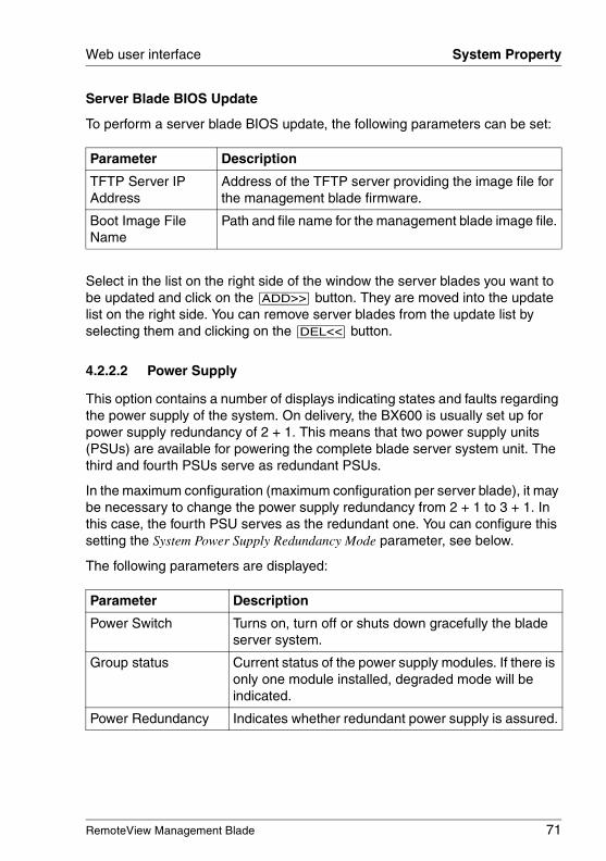
RemoteView Management Blade 71
Web user interface System Property
Server Blade BIOS Update
To perform a server blade BIOS update, the following parameters can be set:
Select in the list on the right side of the window the server blades you want to be updated and click on the [ADD>>] button. They are moved into the update list on the right side. You can remove server blades from the update list by selecting them and clicking on the [DEL<<] button.
4.2.2.2 Power Supply
This option contains a number of displays indicating states and faults regarding the power supply of the system. On delivery, the BX600 is usually set up for power supply redundancy of 2 + 1. This means that two power supply units (PSUs) are available for powering the complete blade server system unit. The third and fourth PSUs serve as redundant PSUs.
In the maximum configuration (maximum configuration per server blade), it may be necessary to change the power supply redundancy from 2 + 1 to 3 + 1. In this case, the fourth PSU serves as the redundant one. You can configure this setting the System Power Supply Redundancy Mode parameter, see below.
The following parameters are displayed:
Parameter Description
TFTP Server IP Address
Address of the TFTP server providing the image file for the management blade firmware.
Boot Image File Name
Path and file name for the management blade image file.
Parameter Description
Power Switch Turns on, turn off or shuts down gracefully the blade server system.
Group status Current status of the power supply modules. If there is only one module installed, degraded mode will be indicated.
Power Redundancy Indicates whether redundant power supply is assured.
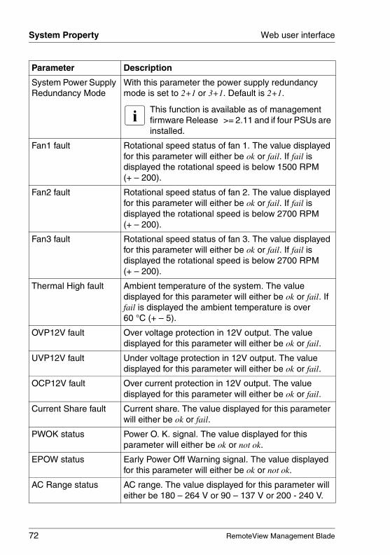
72 RemoteView Management Blade
System Property Web user interface
© c
ogn
itas.
Ge
sells
chft
für
Tech
nik-
Dok
um
enta
tion
mbH
200
7 P
fad
: H:\w
indo
ws\
_pro
jekt
e\A
KV
M\B
X_M
anag
emen
t\bx-
man
bla
de.k
04
System Power Supply Redundancy Mode
With this parameter the power supply redundancy mode is set to 2+1 or 3+1. Default is 2+1.
I This function is available as of management firmware Release >= 2.11 and if four PSUs are installed.
Fan1 fault Rotational speed status of fan 1. The value displayed for this parameter will either be ok or fail. If fail is displayed the rotational speed is below 1500 RPM (+ – 200).
Fan2 fault Rotational speed status of fan 2. The value displayed for this parameter will either be ok or fail. If fail is displayed the rotational speed is below 2700 RPM (+ – 200).
Fan3 fault Rotational speed status of fan 3. The value displayed for this parameter will either be ok or fail. If fail is displayed the rotational speed is below 2700 RPM (+ – 200).
Thermal High fault Ambient temperature of the system. The value displayed for this parameter will either be ok or fail. If fail is displayed the ambient temperature is over 60 °C (+ – 5).
OVP12V fault Over voltage protection in 12V output. The value displayed for this parameter will either be ok or fail.
UVP12V fault Under voltage protection in 12V output. The value displayed for this parameter will either be ok or fail.
OCP12V fault Over current protection in 12V output. The value displayed for this parameter will either be ok or fail.
Current Share fault Current share. The value displayed for this parameter will either be ok or fail.
PWOK status Power O. K. signal. The value displayed for this parameter will either be ok or not ok.
EPOW status Early Power Off Warning signal. The value displayed for this parameter will either be ok or not ok.
AC Range status AC range. The value displayed for this parameter will either be 180 – 264 V or 90 – 137 V or 200 - 240 V.
Parameter Description
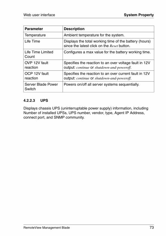
RemoteView Management Blade 73
Web user interface System Property
4.2.2.3 UPS
Displays chassis UPS (uninterruptable power supply) information, including Number of installed UPSs, UPS number, vendor, type, Agent IP Address, connect port, and SNMP community.
Temperature Ambient temperature for the system.
Life Time Displays the total working time of the battery (hours) since the latest click on the Reset button.
Life Time Limited Count
Configures a max value for the battery working time.
OVP 12V fault reaction
Specifies the reaction to an over voltage fault in 12V output: continue or shutdown-and-poweroff.
OCP 12V fault reaction
Specifies the reaction to an over current fault in 12V output: continue or shutdown-and-poweroff.
Server Blade Power Switch
Powers on/off all server systems sequentially.
Parameter Description
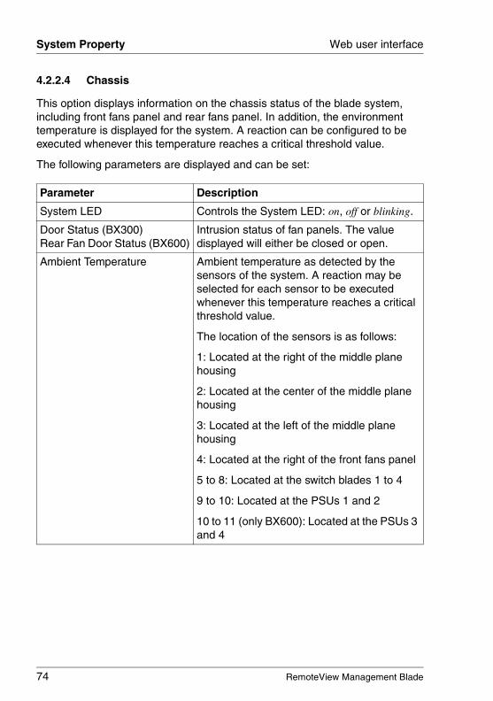
74 RemoteView Management Blade
System Property Web user interface
© c
ogn
itas.
Ge
sells
chft
für
Tech
nik-
Dok
um
enta
tion
mbH
200
7 P
fad
: H:\w
indo
ws\
_pro
jekt
e\A
KV
M\B
X_M
anag
emen
t\bx-
man
bla
de.k
04
4.2.2.4 Chassis
This option displays information on the chassis status of the blade system, including front fans panel and rear fans panel. In addition, the environment temperature is displayed for the system. A reaction can be configured to be executed whenever this temperature reaches a critical threshold value.
The following parameters are displayed and can be set:
Parameter Description
System LED Controls the System LED: on, off or blinking.
Door Status (BX300)Rear Fan Door Status (BX600)
Intrusion status of fan panels. The value displayed will either be closed or open.
Ambient Temperature Ambient temperature as detected by the sensors of the system. A reaction may be selected for each sensor to be executed whenever this temperature reaches a critical threshold value.
The location of the sensors is as follows:
1: Located at the right of the middle plane housing
2: Located at the center of the middle plane housing
3: Located at the left of the middle plane housing
4: Located at the right of the front fans panel
5 to 8: Located at the switch blades 1 to 4
9 to 10: Located at the PSUs 1 and 2
10 to 11 (only BX600): Located at the PSUs 3 and 4
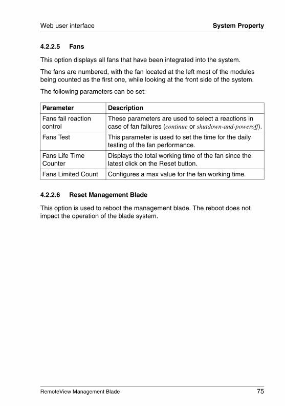
RemoteView Management Blade 75
Web user interface System Property
4.2.2.5 Fans
This option displays all fans that have been integrated into the system.
The fans are numbered, with the fan located at the left most of the modules being counted as the first one, while looking at the front side of the system.
The following parameters can be set:
4.2.2.6 Reset Management Blade
This option is used to reboot the management blade. The reboot does not impact the operation of the blade system.
Parameter Description
Fans fail reaction control
These parameters are used to select a reactions in case of fan failures (continue or shutdown-and-poweroff).
Fans Test This parameter is used to set the time for the daily testing of the fan performance.
Fans Life Time Counter
Displays the total working time of the fan since the latest click on the Reset button.
Fans Limited Count Configures a max value for the fan working time.
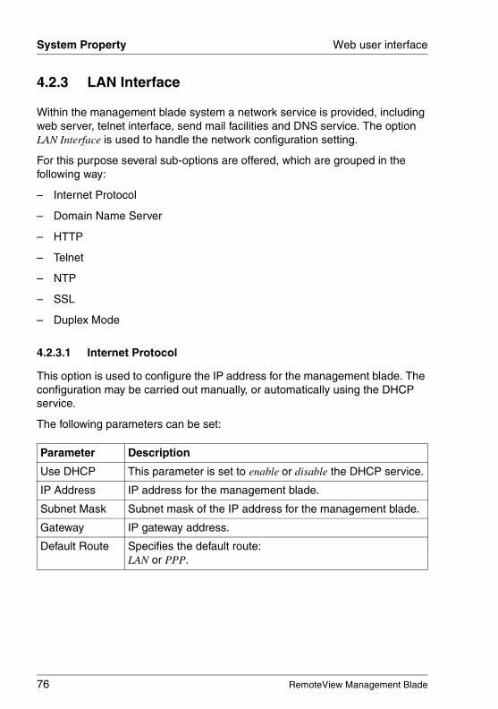
76 RemoteView Management Blade
System Property Web user interface
© c
ogn
itas.
Ge
sells
chft
für
Tech
nik-
Dok
um
enta
tion
mbH
200
7 P
fad
: H:\w
indo
ws\
_pro
jekt
e\A
KV
M\B
X_M
anag
emen
t\bx-
man
bla
de.k
04
4.2.3 LAN Interface
Within the management blade system a network service is provided, including web server, telnet interface, send mail facilities and DNS service. The option LAN Interface is used to handle the network configuration setting.
For this purpose several sub-options are offered, which are grouped in the following way:
– Internet Protocol
– Domain Name Server
– HTTP
– Telnet
– NTP
– SSL
– Duplex Mode
4.2.3.1 Internet Protocol
This option is used to configure the IP address for the management blade. The configuration may be carried out manually, or automatically using the DHCP service.
The following parameters can be set:
Parameter Description
Use DHCP This parameter is set to enable or disable the DHCP service.
IP Address IP address for the management blade.
Subnet Mask Subnet mask of the IP address for the management blade.
Gateway IP gateway address.
Default Route Specifies the default route: LAN or PPP.
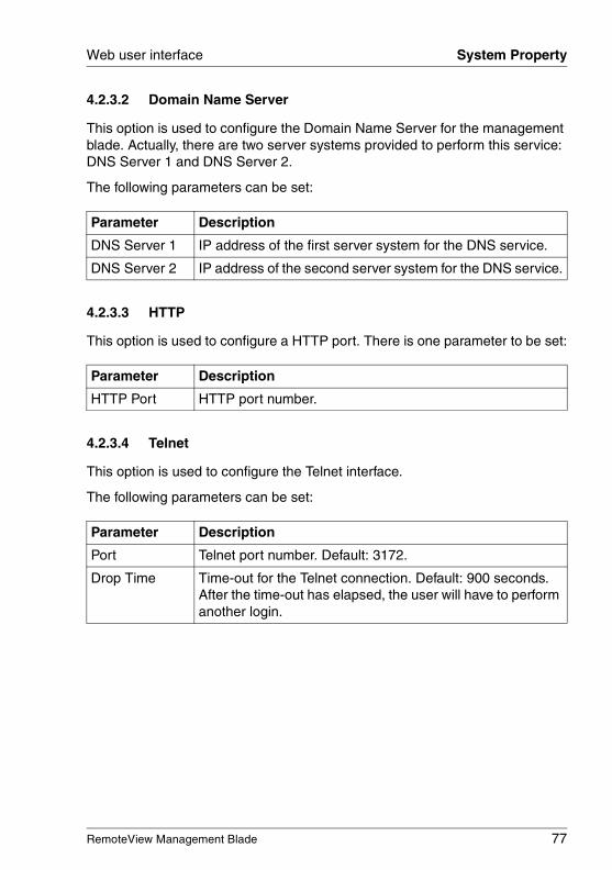
RemoteView Management Blade 77
Web user interface System Property
4.2.3.2 Domain Name Server
This option is used to configure the Domain Name Server for the management blade. Actually, there are two server systems provided to perform this service: DNS Server 1 and DNS Server 2.
The following parameters can be set:
4.2.3.3 HTTP
This option is used to configure a HTTP port. There is one parameter to be set:
4.2.3.4 Telnet
This option is used to configure the Telnet interface.
The following parameters can be set:
Parameter Description
DNS Server 1 IP address of the first server system for the DNS service.
DNS Server 2 IP address of the second server system for the DNS service.
Parameter Description
HTTP Port HTTP port number.
Parameter Description
Port Telnet port number. Default: 3172.
Drop Time Time-out for the Telnet connection. Default: 900 seconds. After the time-out has elapsed, the user will have to perform another login.
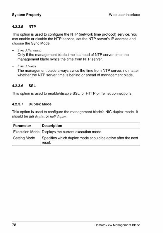
78 RemoteView Management Blade
System Property Web user interface
© c
ogn
itas.
Ge
sells
chft
für
Tech
nik-
Dok
um
enta
tion
mbH
200
7 P
fad
: H:\w
indo
ws\
_pro
jekt
e\A
KV
M\B
X_M
anag
emen
t\bx-
man
bla
de.k
04
4.2.3.5 NTP
This option is used to configure the NTP (network time protocol) service. You can enable or disable the NTP service, set the NTP server’s IP address and choose the Sync Mode:
– Sync AfterwardsOnly if the management blade time is ahead of NTP server time, the management blade syncs the time from NTP server.
– Sync AlwaysThe management blade always syncs the time from NTP server, no matter whether the NTP server time is behind or ahead of management blade,
4.2.3.6 SSL
This option is used to enable/disable SSL for HTTP or Telnet connections.
4.2.3.7 Duplex Mode
This option is used to configure the management blade’s NIC duplex mode. It should be full duplex or half duplex.
Parameter Description
Execution Mode Displays the current execution mode.
Setting Mode Specifies which duplex mode should be active after the next reset.
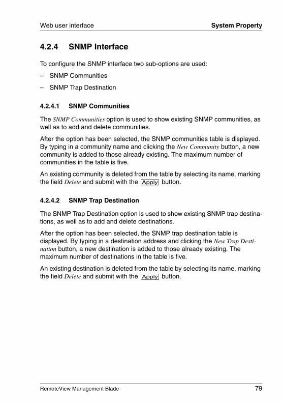
RemoteView Management Blade 79
Web user interface System Property
4.2.4 SNMP Interface
To configure the SNMP interface two sub-options are used:
– SNMP Communities
– SNMP Trap Destination
4.2.4.1 SNMP Communities
The SNMP Communities option is used to show existing SNMP communities, as well as to add and delete communities.
After the option has been selected, the SNMP communities table is displayed. By typing in a community name and clicking the New Community button, a new community is added to those already existing. The maximum number of communities in the table is five.
An existing community is deleted from the table by selecting its name, marking the field Delete and submit with the [Apply] button.
4.2.4.2 SNMP Trap Destination
The SNMP Trap Destination option is used to show existing SNMP trap destina-tions, as well as to add and delete destinations.
After the option has been selected, the SNMP trap destination table is displayed. By typing in a destination address and clicking the New Trap Desti-nation button, a new destination is added to those already existing. The maximum number of destinations in the table is five.
An existing destination is deleted from the table by selecting its name, marking the field Delete and submit with the [Apply] button.
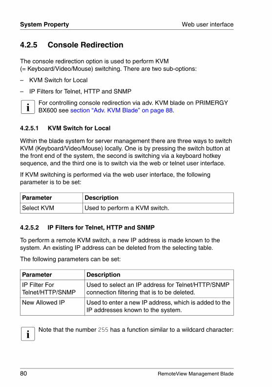
80 RemoteView Management Blade
System Property Web user interface
© c
ogn
itas.
Ge
sells
chft
für
Tech
nik-
Dok
um
enta
tion
mbH
200
7 P
fad
: H:\w
indo
ws\
_pro
jekt
e\A
KV
M\B
X_M
anag
emen
t\bx-
man
bla
de.k
04
4.2.5 Console Redirection
The console redirection option is used to perform KVM (= Keyboard/Video/Mouse) switching. There are two sub-options:
– KVM Switch for Local
– IP Filters for Telnet, HTTP and SNMP
I For controlling console redirection via adv. KVM blade on PRIMERGY BX600 see section “Adv. KVM Blade” on page 88.
4.2.5.1 KVM Switch for Local
Within the blade system for server management there are three ways to switch KVM (Keyboard/Video/Mouse) locally. One is by pressing the switch button at the front end of the system, the second is switching via a keyboard hotkey sequence, and the third one is to switch via the web or telnet user interface.
If KVM switching is performed via the web user interface, the following parameter is to be set:
4.2.5.2 IP Filters for Telnet, HTTP and SNMP
To perform a remote KVM switch, a new IP address is made known to the system. An existing IP address can be deleted from the selecting table.
The following parameters can be set:
I Note that the number 255 has a function similar to a wildcard character:
Parameter Description
Select KVM Used to perform a KVM switch.
Parameter Description
IP Filter For Telnet/HTTP/SNMP
Used to select an IP address for Telnet/HTTP/SNMP connection filtering that is to be deleted.
New Allowed IP Used to enter a new IP address, which is added to the IP addresses known to the system.

RemoteView Management Blade 81
Web user interface System Property
If for example the IP filter list contains the IP filter 255.255.255.255, the system handles all possible IP addresses as known. An IP filter like 192.168.255.255 would handle all IP addresses beginning with 192.168. as known.
82 RemoteView Management Blade
System Property Web user interface
© c
ogn
itas.
Ge
sells
chft
für
Tech
nik-
Dok
um
enta
tion
mbH
200
7 P
fad
: H:\w
indo
ws\
_pro
jekt
e\A
KV
M\B
X_M
anag
emen
t\bx-
man
bla
de.k
04
4.2.6 System Information
This option contains agent information, daylight saving time, controller time, and time-zone configuration.
Daylight Saving Time Format Example
● Start Date Example: M03.5.0/02
Meaning: set the clock ahead one hour at 02:00 am on the Sunday of the last week of the third month.
● End Date Example: M10.4.1/03
Meaning: set the clock back one hour at 03:00 am on the Monday of the fourth week of the tenth month.
4.2.7 User Accounts
Within the server management facilities there is a user database provided to enable user authentication control. New user accounts are added to this database via the Add New User Account option.
There is a static root user, who has full authorization to perform any activities in the user database and cannot be deleted. The default password for this root user is root.
M03 March (Month 03; range: M01-M12)
5 last week (range: 1-5)
0 Sunday (range: 0-6)
02 2:00 o'clock am (range: 00-23)
M10 October (Month 10; range: M01-M12)
4 the fourth week (range: 1-5)
1 Monday (range: 0-6)
03 3:00 o'clock am (range: 00-23)
RemoteView Management Blade 83
Web user interface System Property
When adding a new user account via the Add New User Account option the following parameters are to be set:
4.2.8 Deployment Table
This option is used to display and to set the deployment configuration for each server blade. The particular server blade can be selected from a pull-down list. The parameters are very similar to those of the corresponding Telnet option, thus you can refer to the description in 3.3.12 on page 46).
Parameter Description
Name User name.
Password User password.
Confirm password This field is used to confirm the password entered above.
Permissions The user access rights are set by clicking the options explained below:
Read Only – The user cannot change any settings exceptthe password.
Modify values – The user can change any setting, but is not allowed to add a new user account.
Configure users – The user can change any setting, and isalso allowed to add a new user account.
Reset/Switch off – The user can switch the system on/off.
Access EMP via CLI – The user can access the Emergency Management Port via CLI.
I The following settings refer to the adv. KVM blade, which is only supported by the PRIMERGY BX600.
Adv. KVM User (incl KVM configuration rights) – The user can configure the adv. KVM blade and access the server blades marked below.
blade 1 ... blade 10 – The user can access the marked server blades via Global Viewer.
KVM perm expiration date – Indicates the date when the adv. KVM blade user permissions expire.
84 RemoteView Management Blade
System Property Web user interface
© c
ogn
itas.
Ge
sells
chft
für
Tech
nik-
Dok
um
enta
tion
mbH
200
7 P
fad
: H:\w
indo
ws\
_pro
jekt
e\A
KV
M\B
X_M
anag
emen
t\bx-
man
bla
de.k
04
4.2.9 PPP and Modem Setting
This option is used to configure the settings for PPP connections and to configure the modem. The parameters are very similar to those of the corre-sponding Telnet option, thus you can refer to the description in 3.3.14 on page 51).
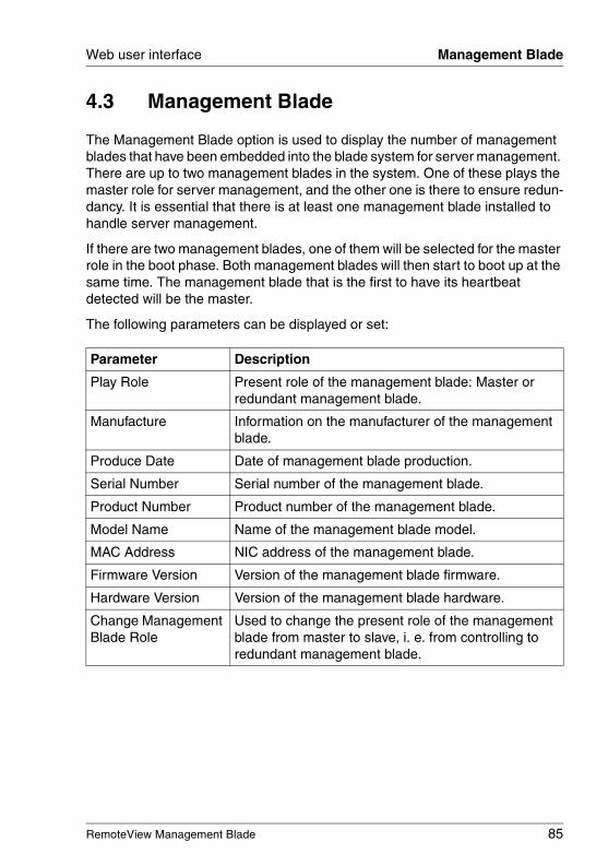
RemoteView Management Blade 85
Web user interface Management Blade
4.3 Management Blade
The Management Blade option is used to display the number of management blades that have been embedded into the blade system for server management. There are up to two management blades in the system. One of these plays the master role for server management, and the other one is there to ensure redun-dancy. It is essential that there is at least one management blade installed to handle server management.
If there are two management blades, one of them will be selected for the master role in the boot phase. Both management blades will then start to boot up at the same time. The management blade that is the first to have its heartbeat detected will be the master.
The following parameters can be displayed or set:
Parameter Description
Play Role Present role of the management blade: Master or redundant management blade.
Manufacture Information on the manufacturer of the management blade.
Produce Date Date of management blade production.
Serial Number Serial number of the management blade.
Product Number Product number of the management blade.
Model Name Name of the management blade model.
MAC Address NIC address of the management blade.
Firmware Version Version of the management blade firmware.
Hardware Version Version of the management blade hardware.
Change Management Blade Role
Used to change the present role of the management blade from master to slave, i. e. from controlling to redundant management blade.

86 RemoteView Management Blade
Switch Blade Web user interface
© c
ogn
itas.
Ge
sells
chft
für
Tech
nik-
Dok
um
enta
tion
mbH
200
7 P
fad
: H:\w
indo
ws\
_pro
jekt
e\A
KV
M\B
X_M
anag
emen
t\bx-
man
bla
de.k
04
4.4 Switch Blade
The Switch Blade option is used to display the number of switch blades that have been embedded into the blade system for server management.
There are two GB NIC ports for each server blade, which connect to two separate switch blades. This has been arranged to ensure LAN connection redundancy.
Up to four switch blades can be installed into the blade system for server management. In each switch blade there are 10 ports for interconnection to the server blades and three ports for outbound links.
4.4.1 Switch Blade Info
The following parameters are displayed for information on a switch blade:
Parameter Description
Located LED Switch on/off the located LED.
Manufacture Information on the manufacturer of the switch blade.
Produce Date Date of switch blade production.
Serial Number Serial number of the switch blade.
Product Number Product number of the switch blade.
Model Name Name of the switch blade model.
Board Version Version of the switch blade board.
Firmware Version Version of the switch blade firmware.
Network Setting Information on the network setting for the switch blade, including the URL address of its web home page.
Mac Address NIC address of the switch blade.
URL URL address of the web home page for the switch blade.
IP Address Setting Value:Specifies a new IP address for the switch blade.
Current Value:Displays the current IP address of the switch blade.
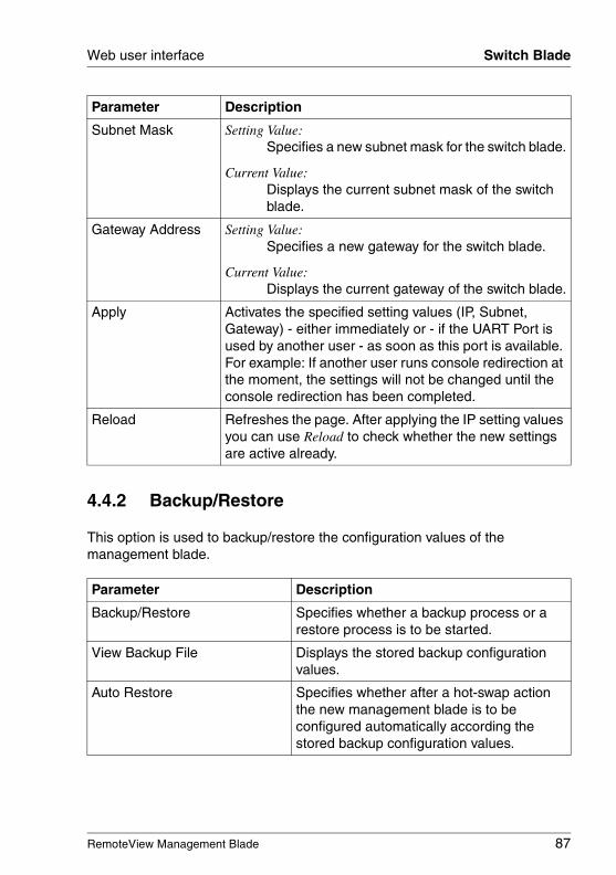
RemoteView Management Blade 87
Web user interface Switch Blade
4.4.2 Backup/Restore
This option is used to backup/restore the configuration values of the management blade.
Subnet Mask Setting Value:Specifies a new subnet mask for the switch blade.
Current Value:Displays the current subnet mask of the switch blade.
Gateway Address Setting Value:Specifies a new gateway for the switch blade.
Current Value:Displays the current gateway of the switch blade.
Apply Activates the specified setting values (IP, Subnet, Gateway) - either immediately or - if the UART Port is used by another user - as soon as this port is available. For example: If another user runs console redirection at the moment, the settings will not be changed until the console redirection has been completed.
Reload Refreshes the page. After applying the IP setting values you can use Reload to check whether the new settings are active already.
Parameter Description
Backup/Restore Specifies whether a backup process or a restore process is to be started.
View Backup File Displays the stored backup configuration values.
Auto Restore Specifies whether after a hot-swap action the new management blade is to be configured automatically according the stored backup configuration values.
Parameter Description
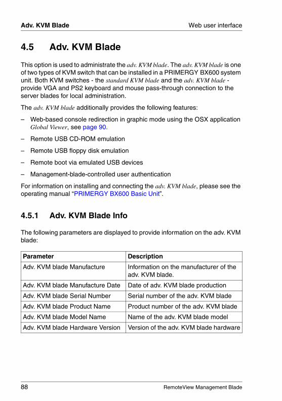
88 RemoteView Management Blade
Adv. KVM Blade Web user interface
© c
ogn
itas.
Ge
sells
chft
für
Tech
nik-
Dok
um
enta
tion
mbH
200
7 P
fad
: H:\w
indo
ws\
_pro
jekt
e\A
KV
M\B
X_M
anag
emen
t\bx-
man
bla
de.k
04
4.5 Adv. KVM Blade
This option is used to administrate the adv. KVM blade. The adv. KVM blade is one of two types of KVM switch that can be installed in a PRIMERGY BX600 system unit. Both KVM switches - the standard KVM blade and the adv. KVM blade - provide VGA and PS2 keyboard and mouse pass-through connection to the server blades for local administration.
The adv. KVM blade additionally provides the following features:
– Web-based console redirection in graphic mode using the OSX application Global Viewer, see page 90.
– Remote USB CD-ROM emulation
– Remote USB floppy disk emulation
– Remote boot via emulated USB devices
– Management-blade-controlled user authentication
For information on installing and connecting the adv. KVM blade, please see the operating manual “PRIMERGY BX600 Basic Unit”.
4.5.1 Adv. KVM Blade Info
The following parameters are displayed to provide information on the adv. KVM blade:
Parameter Description
Adv. KVM blade Manufacture Information on the manufacturer of the adv. KVM blade.
Adv. KVM blade Manufacture Date Date of adv. KVM blade production
Adv. KVM blade Serial Number Serial number of the adv. KVM blade
Adv. KVM blade Product Name Product number of the adv. KVM blade
Adv. KVM blade Model Name Name of the adv. KVM blade model
Adv. KVM blade Hardware Version Version of the adv. KVM blade hardware
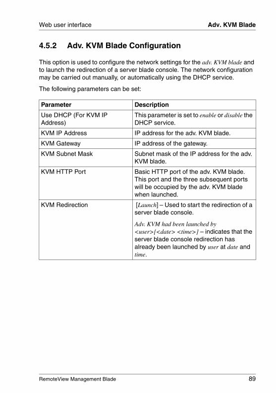
RemoteView Management Blade 89
Web user interface Adv. KVM Blade
4.5.2 Adv. KVM Blade Configuration
This option is used to configure the network settings for the adv. KVM blade and to launch the redirection of a server blade console. The network configuration may be carried out manually, or automatically using the DHCP service.
The following parameters can be set:
Parameter Description
Use DHCP (For KVM IP Address)
This parameter is set to enable or disable the DHCP service.
KVM IP Address IP address for the adv. KVM blade.
KVM Gateway IP address of the gateway.
KVM Subnet Mask Subnet mask of the IP address for the adv. KVM blade.
KVM HTTP Port Basic HTTP port of the adv. KVM blade. This port and the three subsequent ports will be occupied by the adv. KVM blade when launched.
KVM Redirection [Launch] – Used to start the redirection of a server blade console.
Adv. KVM had been launched by <user>[<date> <time>] – indicates that the server blade console redirection has already been launched by user at date and time.
90 RemoteView Management Blade
Adv. KVM Blade Web user interface
© c
ogn
itas.
Ge
sells
chft
für
Tech
nik-
Dok
um
enta
tion
mbH
200
7 P
fad
: H:\w
indo
ws\
_pro
jekt
e\A
KV
M\B
X_M
anag
emen
t\bx-
man
bla
de.k
04
4.5.3 Global Viewer
For the redirection of a server blade VGA screen, the adv. KVM blade provides the Global Viewer. The Global Viewer is an OSX application that will be downloaded from the adv. KVM blade when the user selects KVM Redirection – launch from the KVM Configuration menu. Via a drop-down menu, Global Viewer provides all the functions needed to select the server blades and emulated volumes and to configure the video screen redirection.
4.5.3.1 Requirements
Global Viewer requires the Microsoft Windows operating system running on the client computer. Internet Explorer must be used for the management blade web user interface session when launching Global Viewer.
Also make sure that ActiveX controls are enabled on the client computer before launching Global Viewer.
I For safety reasons it is recommended to restrict ActiveX controls to trusted sites. Proceed as follows to add the adv. KVM blade to the trusted sites and to enable ActiveX controls for the trusted sites.
Ê Go to the Internet Explorer menu Tools - Internet Options - Security.
Ê Select Trusted sites.
Ê Click Sites to open the Trusted sites menu.
Ê Enter http://address into the field Add this site to the zone, where address is the IP address of the adv. KVM blade.
Ê Click the Add button to confirm the entry.
Ê Click the Close button to exit the Trusted sites menu.
Ê Select Custom Level.
Ê Enable all the security options for downloading and executing ActiveX controls.
On the server blade to be redirected, the mouse pointer acceleration must be disabled. This is necessary for the synchronization of the server blade mouse and the client computer mouse. The settings for this purpose depend on the operating system of the redirected server blade.
RemoteView Management Blade 91
Web user interface Adv. KVM Blade
If Windows is running on the server blade, select the mouse properties menu from the control panel.
Win2000:
Ê Go to the Motion menu.
Ê Deactivate the mouse pointer acceleration.
Ê Set the mouse speed to the default of 50%.
Win2003/WinXP:
Ê Enter the Pointer Options menu.
Ê Disable Enhance pointer precision.
If a Linux X Window session is running on the server blade, enter the command xset m 1.
It is recommended that you insert this command in the /etc/profile of the server blade to automate this setting. Use the following statement for this setting:
if [ $DISPLAY ] ; then
xset m 1
fi
I When installing RedHat or SuSE Linux on a server blade via adv. KVM blade, you should use a text mode, keyboard-based installation program instead of a graphical installation program. This is why mouse synchro-nization is not feasible during that phase.
I You must disable mouse pointer acceleration for each server blade that is to be redirected via adv. KVM blade.
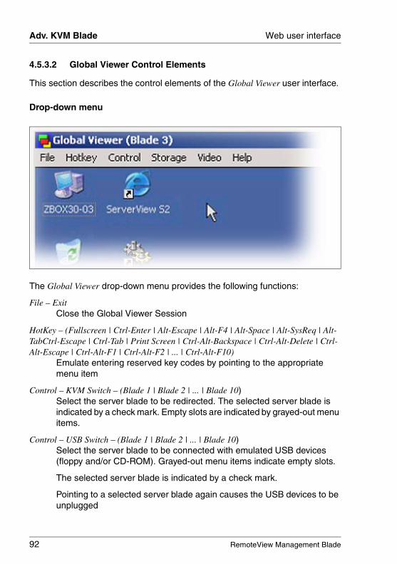
92 RemoteView Management Blade
Adv. KVM Blade Web user interface
© c
ogn
itas.
Ge
sells
chft
für
Tech
nik-
Dok
um
enta
tion
mbH
200
7 P
fad
: H:\w
indo
ws\
_pro
jekt
e\A
KV
M\B
X_M
anag
emen
t\bx-
man
bla
de.k
04
4.5.3.2 Global Viewer Control Elements
This section describes the control elements of the Global Viewer user interface.
Drop-down menu
The Global Viewer drop-down menu provides the following functions:
File – ExitClose the Global Viewer Session
HotKey – (Fullscreen | Ctrl-Enter | Alt-Escape | Alt-F4 | Alt-Space | Alt-SysReq | Alt-TabCtrl-Escape | Ctrl-Tab | Print Screen | Ctrl-Alt-Backspace | Ctrl-Alt-Delete | Ctrl-Alt-Escape | Ctrl-Alt-F1 | Ctrl-Alt-F2 | ... | Ctrl-Alt-F10)
Emulate entering reserved key codes by pointing to the appropriate menu item
Control – KVM Switch – (Blade 1 | Blade 2 | ... | Blade 10)Select the server blade to be redirected. The selected server blade is indicated by a check mark. Empty slots are indicated by grayed-out menu items.
Control – USB Switch – (Blade 1 | Blade 2 | ... | Blade 10)Select the server blade to be connected with emulated USB devices (floppy and/or CD-ROM). Grayed-out menu items indicate empty slots.
The selected server blade is indicated by a check mark.
Pointing to a selected server blade again causes the USB devices to be unplugged
RemoteView Management Blade 93
Web user interface Adv. KVM Blade
Control – Image Response Time – (Fast | High | Middle | Low)Select the video image response time. Higher frame rates require more LAN bandwidth.
Control – Image Sampling – (4:1:1 | 4:4:4).Select the color depth. The default value is 4:1:1 and requires lower bandwidth.
Control – Image Quality – (Best | High | Better | Normal)Select the image quality (sharpness, etc.). Better quality requires more LAN bandwidth or results in lower frame rates.
Control – Connection timeout setting Timeout for reconnecting Global Viewer if the connection would be lost. The default timeout value is 30 seconds.
Control – Mouse SyncSynchronize the mouse pointer between client and server blade.
Storage – USB CDROM – CDROM EmulationSelect a CD-ROM drive of the client to be connected to the selected server blade as an emulated USB device.
Select No Emulation for no CD-ROM emulation.
Storage – USB Floppy – Floppy EmulationSelect a floppy drive of the client or HDD stored floppy image. The contents of the selected floppy or floppy image will be loaded into the adv. KVM blade. Then the adv. KVM blade is able to emulate the floppy for the selected server blade.
Select No Emulation for no floppy emulation.
Storage – USB Floppy – Mount Floppy DrivePlug in the emulated USB floppy drive. The selected server blade gets access to the floppy image stored in the adv. KVM blade. The text of the menu item toggles to Unmount Floppy Drive.
Storage – USB Floppy – Unmount Floppy DriveUnplug the emulated USB floppy drive. Now the local USB floppy drive can be accessed by the server blade. The text of the menu item toggles to Mount Floppy Drive.
Storage – USB Floppy – Save Image ToSave the contents of the emulated floppy. This will cause the floppy image to be saved from the adv. KVM blade to a selected floppy drive or as an image file to the specified file on an HDD of the client.
94 RemoteView Management Blade
Adv. KVM Blade Web user interface
© c
ogn
itas.
Ge
sells
chft
für
Tech
nik-
Dok
um
enta
tion
mbH
200
7 P
fad
: H:\w
indo
ws\
_pro
jekt
e\A
KV
M\B
X_M
anag
emen
t\bx-
man
bla
de.k
04
Video – BrightnessOpens a menu for adjusting the brightness of the Global Viewer window by means of scale bars for base signal and red, green and blue separately.
Video – ContrastOpens a menu for adjusting the contrast of the Global Viewer window by means of scale bars for base signal and red, green and blue separately.
Video – Auto AdjustVideo settings will be adjusted automatically. This will require ten seconds, during which Global Viewer will be locked.
Video – Load Default SettingThe factory settings will be loaded.
Video – Save ConfigurationThe current video settings will be stored permanently.
Help – AboutDisplays the Global Viewer firmware version.
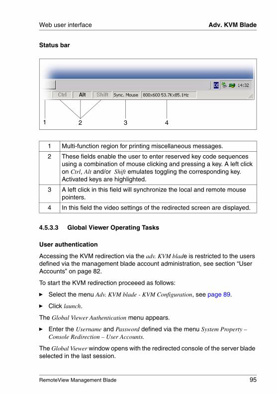
RemoteView Management Blade 95
Web user interface Adv. KVM Blade
Status bar
4.5.3.3 Global Viewer Operating Tasks
User authentication
Accessing the KVM redirection via the adv. KVM blade is restricted to the users defined via the management blade account administration, see section “User Accounts” on page 82.
To start the KVM redirection proceeed as follows:
Ê Select the menu Adv. KVM blade - KVM Configuration, see page 89.
Ê Click launch.
The Global Viewer Authentication menu appears.
Ê Enter the Username and Password defined via the menu System Property – Console Redirection – User Accounts.
The Global Viewer window opens with the redirected console of the server blade selected in the last session.
1 Multi-function region for printing miscellaneous messages.
2 These fields enable the user to enter reserved key code sequences using a combination of mouse clicking and pressing a key. A left click on Ctrl, Alt and/or Shift emulates toggling the corresponding key. Activated keys are highlighted.
3 A left click in this field will synchronize the local and remote mouse pointers.
4 In this field the video settings of the redirected screen are displayed.
2 3 41
96 RemoteView Management Blade
Adv. KVM Blade Web user interface
© c
ogn
itas.
Ge
sells
chft
für
Tech
nik-
Dok
um
enta
tion
mbH
200
7 P
fad
: H:\w
indo
ws\
_pro
jekt
e\A
KV
M\B
X_M
anag
emen
t\bx-
man
bla
de.k
04
Synchronizing the mouse
To operate the redirected console smoothly, you must synchronize the mouse pointer of server blade ( ) with the mouse pointer of the management client ( ).
V CAUTION!
Make sure that mouse pointer acceleration is disabled on the server blade to be redirected, see section “Requirements” on page 90. With mouse pointer acceleration enabled, mouse synchronization is not feasible.
There are four ways to synchronize the mouse:
– Select Control – Mouse Sync from the Global Viewer drop-down menu.
– Left-click in the Sync. Mouse field of the Global Viewer status bar.
– Double-click the left and right mouse buttons simultaneously.
– Move the mouse pointer over any boundary (menu bar, scroll bar or status bar) of the activated Global Viewer window.
I You must synchronize the mouse every time you activate the Global Viewer window.
How to select a server blade for console redirection
Ê Select the menu Control – KVM Switch.
Ê Select the server blade to be redirected.
How to select a server blade for USB volume emulation
Ê Select the menu Control – USB Switch.
Ê Select the server blade to be connected to a CD-ROM drive or floppy disk drive of the remote client via USB volume emulation.
How to specify a remote CD-ROM drive to be connected to a server blade
Ê Select the menu Storage – CDROM Emulation.
Ê Select the CD-ROM drive to be emulated as a remote USB volume.
Ê If no CD-ROM drive is to be emulated, select No Emulation.
RemoteView Management Blade 97
Web user interface Adv. KVM Blade
How to specify a remote floppy disk drive to be connected to a server blade
Ê Select the menu Storage – USB Floppy – Floppy Emulation.
Ê Select the floppy disk drive or the floppy disk image to be emulated as a remote USB volume of a server blade.
The selected floppy disk drive or floppy disk image will be copied into the memory of the adv. KVM blade to be emulated as a remote USB floppy of a specified server blade until the end of the Global Viewer session.
To connect the emulated USB floppy drive to a selected server blade you must execute the function Mount Floppy Drive, see below.
Ê Select Mount Floppy Drive to emulate plugging the remote floppy in the specified server blade.
Ê Select Unmount Floppy Drive to emulate unplugging the remote floppy from the specified server blade.
Ê Select Save Image to ... to save the emulated floppy from the adv. KVM blade to the specified floppy drive or an image file on a hard disk.
4.5.4 Adv. KVM Blade Update
This option is used to perform a firmware update for the adv. KVM blade. The upgrade is performed via the TFTP service. The current adv. KVM blade firmware version is printed at the top of the menu.
To perform an adv. KVM blade update, you can set the following parameters:
Parameter Description
Image Name File name of the adv. KVM blade image file.
TFTP Server IP Address
Address of the TFTP server providing the image file for the adv. KVM blade firmware.
Update Firmware Used to start the firmware update process.
Firmware Update Status
Used to display the progress of the update process in a new window.
98 RemoteView Management Blade
Server Blade Web user interface
© c
ogn
itas.
Ge
sells
chft
für
Tech
nik-
Dok
um
enta
tion
mbH
200
7 P
fad
: H:\w
indo
ws\
_pro
jekt
e\A
KV
M\B
X_M
anag
emen
t\bx-
man
bla
de.k
04
4.6 Server Blade
The web user interface for server management provides a number of options to display information on the server blades that have been embedded into the system. The maximum number of server blades that can be embedded is 20 for BX300 Systems and 10 for BX600 Systems.
In front of each server blade system that is displayed on the web page there is an icon showing the power status of the server blade and the KVM (= Keyboard/Video/Mouse) location.
The following icons are used for this purpose:
Means that the server blade is in power off state.
Means that the server blade is in power on state.
Means that the server blade is in power off state and KVM is located at this blade.
Means that the server blade is in power on state and KVM is located at this blade.
There are two parameters that can be set to activate or deactivate the server blades collectively:
Parameter Description
Turn on all server blades
Power on all server blades sequentially.
Turn off all server blades
Power off all server blades sequentially.
RemoteView Management Blade 99
Web user interface Server Blade
4.6.1 Recovery
The recovery options provided by the system for server management have been arranged into four groups:
– Automatic Server Restart (ASR)
– Auto Configuration
– Power Control
– Boot Option
4.6.1.1 Automatic Server Restart (ASR)
Using this option the Boot Watchdog timer can be enabled or disabled and a time-out can be configured. When the time-out has been reached, the Watchdog Action is executed. The restart is retried until the boot is successful or until the value Maximum restart retries is reached.
4.6.1.2 Auto Configuration
There is one parameter that can be set to backup the CMOS configuration of the server blades, and another one to restore it:
Parameter Description
CMOS Backup Used to generate a backup of the BIOS parameters for the server blade. The server blade must be powered up, before the backup can be generated. If the backup has been generated successfully, it will appear in the CMOS file selecting table.
CMOS Restore
Used to restore the server blade parameters. To do this, a CMOS file is selected and the Restore Policy parameter is set. If the special option smart Restore is selected, the server blade parameters will be restored with MAC address and slot ID.
100 RemoteView Management Blade
Server Blade Web user interface
© c
ogn
itas.
Ge
sells
chft
für
Tech
nik-
Dok
um
enta
tion
mbH
200
7 P
fad
: H:\w
indo
ws\
_pro
jekt
e\A
KV
M\B
X_M
anag
emen
t\bx-
man
bla
de.k
04
4.6.1.3 Power Control
Using this option, the power on/off procedure can be configured for the server blades. It is then performed according to a schedule table, instead of having power on and off performed manually.
4.6.1.4 Boot Option
Using this option, a boot option can be selected for the server blade. If the PXE boot option is selected, the server blade will try to boot up from the PXE server.
4.6.2 Blade Info
The Blade Info options have been arranged into four groups:
– Blade Info
– Memory Module
– Voltage
– Temperature
This option is used to display information on the server blades and their config-uration.
4.6.2.1 Blade Info
The following parameters are displayed:
Parameter Description
Blade Status Displays the server blade health status.
Server LED Configuration of the LED control at the front of the blade server: blinking or off.
OS Type Displays the OS platform currently running on the server blade.
OS Version Displays the version of the OS currently running on the server blade.
Model Name of the server blade model.
Serial Number Serial number of the server blade.
BIOS Version Version of the server blade BIOS.
RemoteView Management Blade 101
Web user interface Server Blade
4.6.2.2 Memory Module
The following parameters are displayed:
Firmware Version Version of the server blade firmware.
KME Version Version of the keyboard/mouse emulation.
Hardware Version Displays server blade hardware version information.
Product Name Displays server blade product name information.
Product Version Displays server blade product version information.
Manufacture Date Displays server blade manufacture date information.
PCI Add-In Card Displays whether a PCI card is installed.
FSC Daughter Card
Displays whether a FC (Fibre Channel) daughter card is installed (only relevant for BX600 Blade Server Systems).
Processors Information on the CPUs, including type, frequency, CPU stepping, and socket type.
Network Interface Card
Displays physical addresses and IP address of the server blade’s network interface cards.
Parameter Description
Status Displays the status of the memory module. Possible values: ok or not-available.
Module Size Displays memory module size.
Type Displays the type of the memory module (e.g. ECC.DIMM.SDRAM).
Speed Displays the speed of the memory module (e.g. 133).
Socket Designation Displays the designation of the memory module (e.g. DIMM1).
Parameter Description
102 RemoteView Management Blade
Server Blade Web user interface
© c
ogn
itas.
Ge
sells
chft
für
Tech
nik-
Dok
um
enta
tion
mbH
200
7 P
fad
: H:\w
indo
ws\
_pro
jekt
e\A
KV
M\B
X_M
anag
emen
t\bx-
man
bla
de.k
04
4.6.2.3 Voltage
This option is used to display a voltage summary of the server blade.
4.6.2.4 Temperature
This option is used to display a voltage summary of the server blade.
RemoteView Management Blade 103
Related publicationsPRIMERGY manuals are available in PDF format on the ServerBooks CD. The ServerBooks CD is part of the ServerStart Bundle delivered with each server system.
The PDF files for the manuals can also be downloaded free of charge from the Internet. The overview page showing the online documentation available in the Internet can be found via the URL:
http://manuals.fujitsu-siemens.com
I You will find further useful information in the documentation for your operating system.
[1] PRIMERGY BX 300 Blade Server System Operating Manual
[2] PRIMERGY BX600 Basic UnitOperating Manual
[3] PRIMERGY BX Blade Server SystemsLAN Switch Blade - User Interface Description User Guide
[4] RemoteDeployUser Manual
[5] BIOS-Setup Reference Manual
[6] ServerStart User Guide
[7] RemoteView User Guide
[8] ServerView User Guide

© c
ogn
itas.
Ge
sells
chft
für
Tech
nik
-Do
kum
enta
tion
mbH
200
7
Pfa
d: H
:\win
dow
s\_p
roje
kte
\AK
VM
\BX
_M
anag
em
ent\b
x-m
anbl
ade.
lit
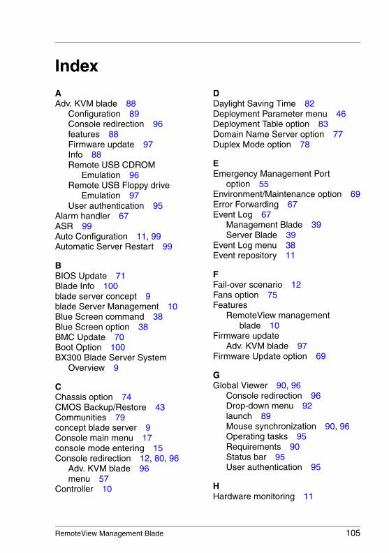
RemoteView Management Blade 105
IndexAAdv. KVM blade 88
Configuration 89Console redirection 96features 88Firmware update 97Info 88Remote USB CDROM
Emulation 96Remote USB Floppy drive
Emulation 97User authentication 95
Alarm handler 67ASR 99Auto Configuration 11, 99Automatic Server Restart 99
BBIOS Update 71Blade Info 100blade server concept 9blade Server Management 10Blue Screen command 38Blue Screen option 38BMC Update 70Boot Option 100BX300 Blade Server System
Overview 9
CChassis option 74CMOS Backup/Restore 43Communities 79concept blade server 9Console main menu 17console mode entering 15Console redirection 12, 80, 96
Adv. KVM blade 96menu 57
Controller 10
DDaylight Saving Time 82Deployment Parameter menu 46Deployment Table option 83Domain Name Server option 77Duplex Mode option 78
EEmergency Management Port
option 55Environment/Maintenance option 69Error Forwarding 67Event Log 67
Management Blade 39Server Blade 39
Event Log menu 38Event repository 11
FFail-over scenario 12Fans option 75Features
RemoteView management blade 10
Firmware updateAdv. KVM blade 97
Firmware Update option 69
GGlobal Viewer 90, 96
Console redirection 96Drop-down menu 92launch 89Mouse synchronization 90, 96Operating tasks 95Requirements 90Status bar 95User authentication 95
HHardware monitoring 11
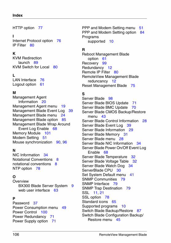
106 RemoteView Management Blade
Index
© c
ogn
itas.
Ges
ells
chft
für
Tech
nik-
Dok
um
enta
tion
mbH
200
7 P
fad
: H:\w
indo
ws\
_pr
oje
kte\
AK
VM
\BX
_Ma
nag
eme
nt\b
x-m
anbl
ade
.six
HTTP option 77
IInternet Protocol option 76IP Filter 80
KKVM Redirection
launch 89KVM Switch for Local 80
LLAN Interface 76Logout option 61
MManagement Agent
Information 20Management Agent menu 19Management Blade Event Log 39Management Blade menu 24Management Blade option 85Management Blade Wrap Around
Event Log Enable 68Memory Module 101Modem Setting 51Mouse synchronization 90, 96
NNIC Information 34Notational Conventions 8notational conventions 8NTP option 78
OOverview
BX300 Blade Server System 9web user interface 63
PPassword 37Power Consumption menu 49Power Control 100Power Redundancy 71Power Supply option 71
PPP and Modem Setting menu 51PPP and Modem Setting option 84Programs
supported 10
RReboot Management Blade
option 61Recovery 99Redundancy 12Remote IP Filter 80RemoteView Management Blade
reduncancy 12Reset Management Blade 75
SServer Blade 98Server Blade BIOS Update 71Server Blade BMC Update 70Server Blade CMOS Backup/Restore
menu 43Server Blade Control Information 28Server Blade Event Log 39Server Blade Information 29Server Blade Memory 31Server Blade menu 28Server Blade NIC Information 34Server Blade Power On/Off Event Log
Enable 68Server Blade Temperature 32Server Blade Voltage Table 32Server Blade Watch Dog 34ServerBlade CPU 30Set System Default menu 41SNMP Communities 79SNMP Interface 79SNMP Trap Destination 79SSL 11, 21SSL option 78Standard icons 65Supported programs 10Switch Blade Backup/Restore 87Switch Blade Configuration Backup/
Restore menu 45
RemoteView Management Blade 107
Index
Switch Blade menu 35Switch Blade option 86System Events Log 66System Information 82System Information Dump option 62System Information menu 26System Property option 66
TTarget Group 8Telnet interface 15Telnet option 77Temperature 102TFTP Update menu 59Trap Destination 79
UUPS option 73User Accounts 82Username and Password menu 37
VVoltage 102
WWatch Dog 34Web user interface 63

© c
ogn
itas.
Ges
ells
chft
für
Tech
nik-
Dok
um
enta
tion
mbH
200
7 P
fad
: H:\w
indo
ws\
_pr
oje
kte\
AK
VM
\BX
_Ma
nag
eme
nt\b
x-m
anbl
ade
.six


![û6^BX]BX M±K - pku.edu.cn](https://img.pdfslide.net/doc/110x75/61736064a433c678797cd078/6bxbx-mk-pkueducn.jpg)