Embed Size (px)
Citation preview
.A D-,752 792
THE DEVELOPMENT OF. A NAVY, !BUOYANT,ANTI-"FRAGMENT, :BULLETPRQOF VEST: PRO--TECTION AGAINST LOW-VELOCITY FRAGMENTS,SECONDARY (SPALL) FRAGMENT DAMAG:E, AND30-CALIBER-BALL PROJECTILES
John ,bilvia, et al
Navy Clothing and Textile Reselarch UnitNatick, Massachusetts,
November 1972
DISTRIBUTED BY:
National Technic'al Information ServiceU. S. DEPARTMENT OF COMMERC5285 Port Royal Road, Springfield Va. 22151'
4'•
THE DEVELOPMENT OF A NAVY, NOYANT, ANTI-FRAGMENT, BULLETPROOF VEST:PrOTE AGAINST LOW-V FROCIAYGMENTS, SECONDARY (SPAII)
FRAGMENT DAMAGE, AND 30-CALIBER-BALL PROJECTILES
21
NAVY CLOTHING AND TEXTILE RESEARCH UNITNATICK, MASSACHUSETTS -D 0
Approved for public release;
distribution unlimited. TECHNICAL REPORT NO. 105
r~
NAVY CLOTHING AND TEXTILE RESEARCH UNITNATICK, MASSACHUSETTS
THE DEVELOPMENT OF A NAVY, BUOYANT, ANTI-FRAGMENT,
BULLETPROOF VEST
Protection Against Low-Velocity Fragments,Secondary (Spall) Fragment Damage, and30-Caliber-Ball Projectiles
by J. Silvia, D.A.Reins, and J.C.Shampine
Work Unit No. Technical Report No.523-003-21 105
Approved for public release; November 1972distribution unlimited
UiNCLASSI.LEDSecurity Classification
DOCUMENT CONTROL DATA- R & D(Security claesificationof tIleM , body of abstract and Indexing annotatlion must be tneted when the overall rep, t Is classitied)
1. ORIGINATING ACTIVITY (Coporete author) i28. REPORT SECUNITY CLASSIFICATION
Navy Clothing and Textile Research Unit UNCLASSIFIEDNatick Laboratories 2b. GROUP
Natick, Massachus-tts 017603. REPORT TITLE
THE DEVELOPMENT OF A NAVY, BUOYANT, ANTI-FRACMENT, BULLETPROOF VEST
4. DESCRIPTIVE NOTES (7ype of repoet end incluelve dotes)
TECHNICAL REPORTS. AUTHOR(S) (Frsht 1ame, middle initial. last name)
John Silvia, Dale A. Reins, and James C. Shampine
6. REPORT DATE 7a. TOTAL NO. OF PAGES 7b. NO. OF REFS
November 1972 1, 2< 9 98&. CONTRACT OR GRANT NO. 9A. ORIGINATORCS REPORT NUIMrIRS)
b. PROJKE'T NO, 523-003-21 105
C. Sb. OTHER REPORT NO(S) (Any Othet nuilbelS 11eti ay be a •lsgnedthis teporl)
2-72
10. DISTRIBUTION STATEMENT
Approved for public release; distribution unlimited.
11 SUPPLMMENTAnY NOTES Detoais c! illustration5 in J,2. SIONSORING MILITARY ACTIVITY
Navy Clothing and Textile Researoh Unitthis docunwn! mt,.v b8 ew Na.ick Laboratoriesiaudied on rnicrofti, "Natick, Massachusetts 01760
1. ABSTRACT
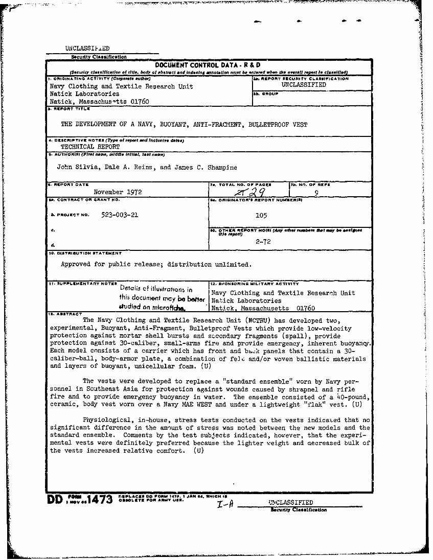
The Navy Clothing and Textile Research Unit (NCTRU) has developed two,experimental, Buoyant, Anti-Fragment, Bulletprcof Vests which provide low-velocityprotection against mortar shell bursts and scecondary fragments (spall), provideprotection against 30-caliber, small-arms fire and provide emergency, inherent buoyancy.Each model consists of a carrier which has front and bhck panels that contain a 30-caliber-ball, body-armor plate, a combination of fe]G and/or woven ballistic materialsand layers of buoyant, unicellular foam. (U)
The vests were developed to replace a "standard ensemble" worn by Navy per-sonnel in Southeast Asia for protection against wounds caused by shrapnel and riflefire and to provide emergency buoyancy in water. The ensemble consisted of a 40-pound,ceramic, body vest worn over a Navy MAE WEST and under a lightweight "flak" vest. (U)
Physiological, in-house, stress tests conducted on the vests indicated that nosignificant difference in the amount of stress was noted between the new models and thestandard ensemble. Comments by the test subjects indicated, however, that the experi-mental vests were definitely preferred because the lighter weight and aecreased bulk ofthe vests increased relative comfort. (U)
DD ,o., 7 PLAC90 DORM 147P. 1 JAN 04. WHICH of FD I_ No *4 3 09LT O AM •.UCLASSIFIEDS•k'Lseuriy% l assif.*" i |1ca tion
UNCLASSIFIEDSecurity Classification
1-4. 'K.E.Y WORDS LIN A LINK 8 LINK CROLE WT ROLE WT ROLE WT
Bnoyant, Anti-Fragment, Bulletproof VestLow-Velocity ProtectionMortar-Shell BurstsSecondary (Spall) Fragments30-Caliber-Ball Projectiles30-Caliber-Ball, Body-Armor PlateBuoyant, Unicellular FoamBuoyancy TestsPhysiological Stress Tests
?)
E
I- 6• UNCLASSIFIEDSecurity Classifletion

TABLE OF CONTENTSPage
List of Illustrations................... ... ........ . ..
List of Tab3es ....................... ................. v
Abstract io......................................................... vii
Introduction . . . . . . . . .............. ........................... 1
Design and Construction ............................................... 2
Standard Ensemble .................................................. 2
Model I, Buoyant, Armor-Piercing, Protective Vest .................... 3
Models II and II-A, Buoyant, Anti-Fragment, Bulletproof Vest ......... 3
Ballistic Protection Characteristics ................................... 4
Buoyancy ............................................................. 5
Description of Test Procedures ...................................... 5
Test Results ....................................................... 6
Discussion of Buoyancy ................................................ 8
Weight ............................................................... 9
Discussionof Weights .................................................. 9
Physiological Stress of the Standard vs. Models II and II-A ............ 9
Activity Levels ...................................................... 10
Test Results and Discussion ........................................... 12
Subjective Comments .................................................... 14
Conclusions and Recommendations ........................................ 14
Appendix A. Illustrations .......................................... A-1
Appendix B. References ................................................ B-I
iii
Preceding page blank
LIST OF ILLUSTRATIONS
Figure Page
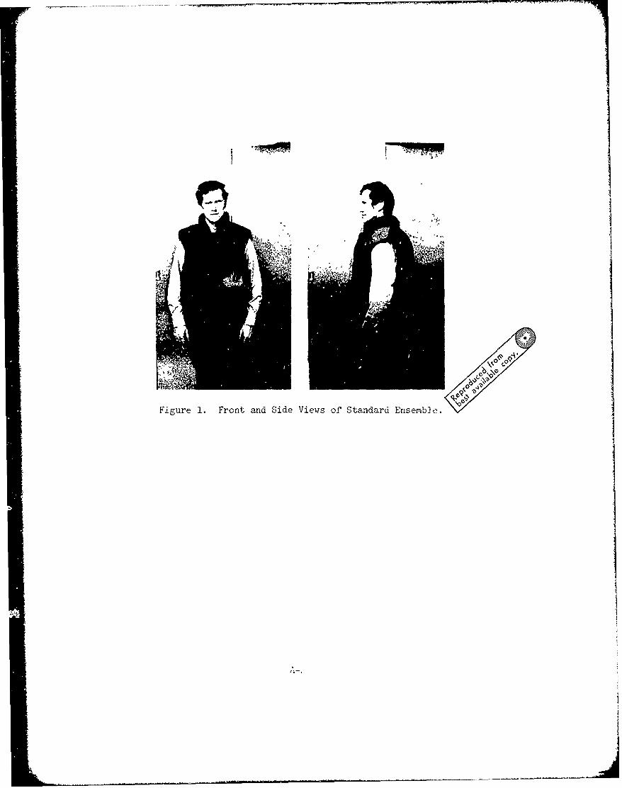
1 Front and Side Views of Standard Ensemble ........................ A-2
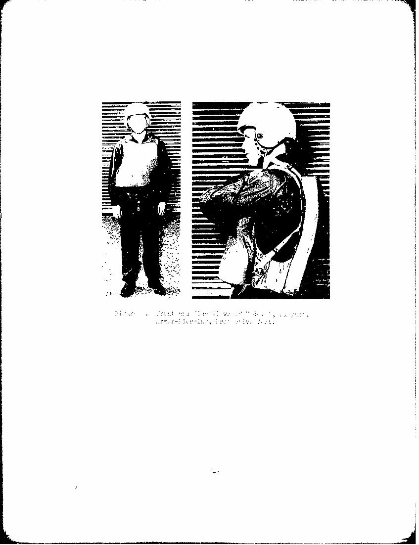
2 Model I, Buoyant, Armor-Piercing, Protective Vest ................ A-3
3 Front and Side Views of Model II, Buoyant, Anti-FragmentBulletproof Vest ................................................. A-h
4 Front and Side Views of Model I-A., Buoyant, Anti-FragmentBulletproof Vest ................................................. A-5
LIST OF TABLES
Table Page
I Buoyancy of Standard Ensemble and Model I, II and II-AVests ........................................................... 7
II Static-Buoyancy Test Results of the Perforated Vest inNCTRU Pool ...................................................... 8
III Summary of Physiological Data ................................... 13 z
Preceding page blank
THE DEVELOPMENT OF A NAVY, BUOYANT, ANTI-FRAGMENT, BULLETPROOF VEST
INTRODUCTION
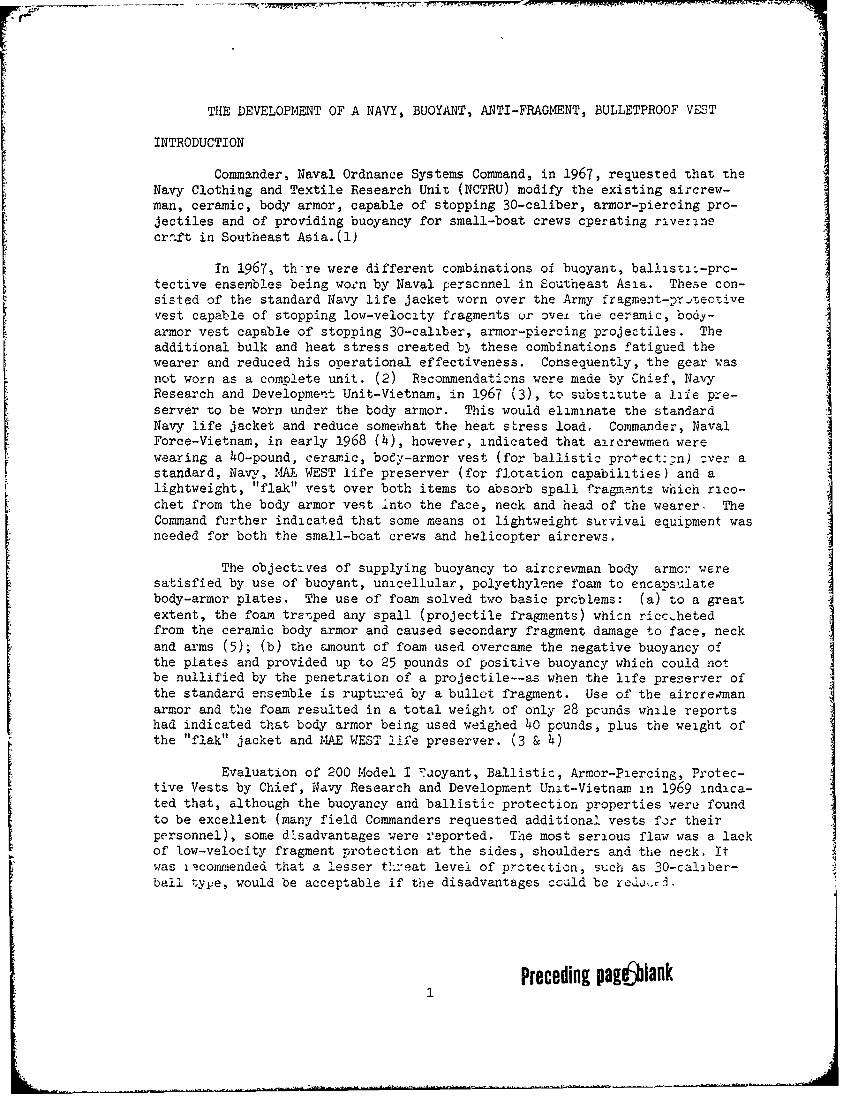
Commander, Naval Ordnance Systems Command, in 1967, requested that theNavy Clothing and Textile Research Unit (NCTRU) modify the existing aircrew-man, ceramic, body armor, capable of stopping 30-caliber, armor-piercing pro-jectiles and of providing buoyancy for small-boat crews operating riverinecraft in Southeast Asia.(l)
In 1967, th-re were different combinations of buoyant, ballisti--prc-tective ensembles being woen by Naval perscnnel in Southeast Asia. These con-sisted of the standard Navy life jacket worn over the Army fragment-prisectivevest capable of stopping low-velocity fragments ur oveL the ceramic, body-armor vest capable of stopping 30-caliber, armor-piercing projectiles. Theadditional bulk and heat stress created bý these combinations fatigued thewearer and reduced his operational effectiveness. Consequently, the gear wasnot worn as a complete unit. (2) Recommendaticns were made by Chief, NavyResearch and Development Unit-Vietnam, in 1967 (3), to substitute a lafe pre-server to be worn under the body armor. This would eliminate the standardNavy life jacket and reduce somewhat the heat stress load. Commander, NavalForce-Vietnam, in early 1968 (4), however, indicated that aircrewmen werewearing a 4 0-pound, ceramic, body-armor vest (for ballistic pro+ect::n) zver astandard, Navy, 1,WA WEST life preserver (for flotation capabilities) and alightweight, "flak" vest over both items to absorb spall fragrnints which rico-chet from the body armor vest into the face, neck and head of the wearer. TheCommand further indicated that some means ol lightweight survival equipment wasneeded for both the small-boat crews and helicopter aircrews.
The objectives of supplying buoyancy to aircrewman body armor weresatisfied by use of buoyant, unicellular, polyethylene foam to encapsulatebody-armor plates. The use of foam solved two basic prcblems: (a) to a greatextent, the foam tre'.ped any spall (projectile fragments) whicn ricchetedfrom the ceramic body armor and caused secondary fragment damage to face, neckand arms (5); (b) the amount of foam used overcame the negative buoyancy ofthe plates and provided up to 25 pounds of positive buoyancy which could notbe nullified by the penetration of a projectile--as when the life preoerver of
the standard ensemble is ruptured by a bullet fragment. Use of the aircrennanarmor and the foam resulted in a total weight of only 28 pounds while reportshad indicated that body armor being used weighed 40 pounds, plus the weight ofthe "flak" jacket and MAE WEST life preserver. (3 & 4)
Evaluation of 200 Model i 'Xaoyant, Ballistic, Armor-Piercing, Protec-tive Vests by Chief, Navy Research and Development Unit-Vietnam in 1969 indica-ted that, although the buoyancy and ballistic protection properties were foundto be excellent (many field Commanders requested additional vests for theirpersonnel), some disadvantages were reported. The most serious flaw was a lackof low-velocity fragment protection at the sides, shoulders and the neck, Itwas iicoavqended that a lesser th..at level of protection, such as 30-calmber-ball type, would be acceptable if the disadvantages could be redi,.J.
Preceding page lank
Tnis rey•jrt w.±± cover tne aesign and conszruciotOi o! •e eazx•±erbuoyant, balli Aic, protective items and the two newer modelo, .. discussion ofthe various items' protective and physical characteristics, inc`-,ding test
data and results, and a physiological stress test of the earlie, 2tandard
ensemble and ;be latest ;:r o3e.'s.
DESIGN AND CONSTRUCTION
;tandard Ensemble
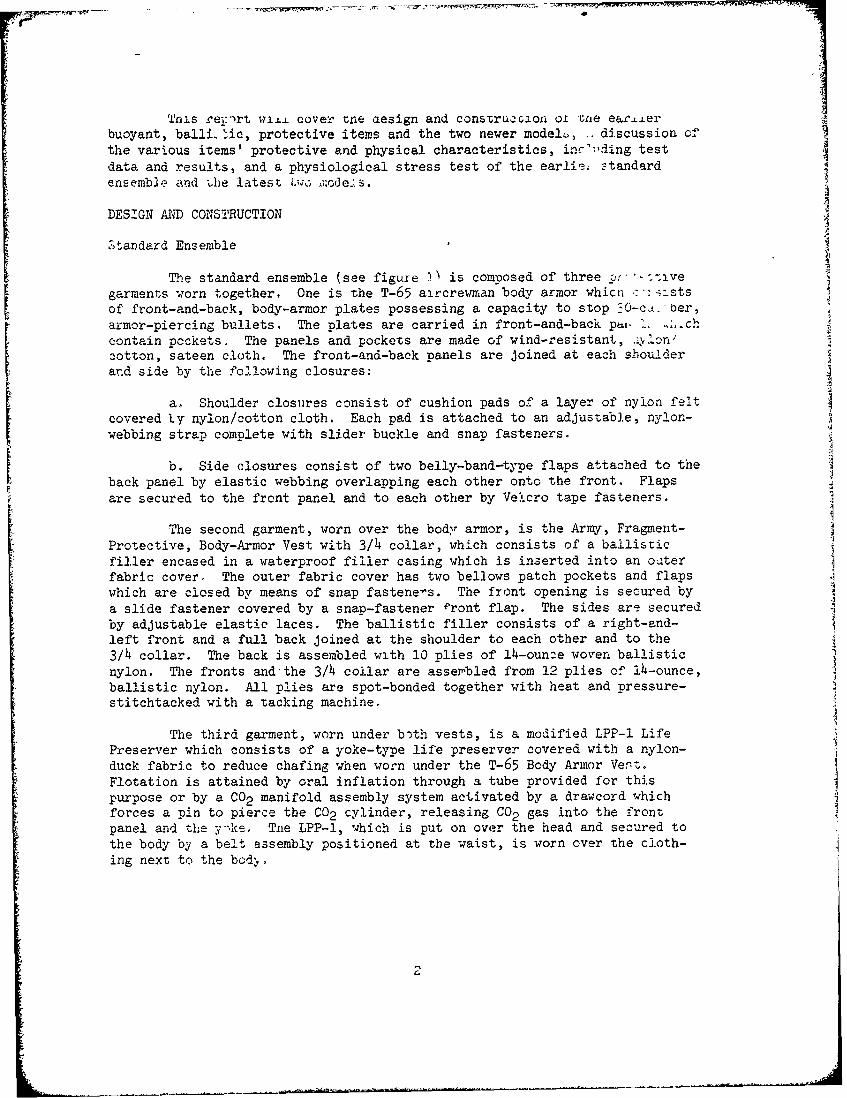
The standard ensemble (see figure • is composed of three p:r-;ivegarments worn together, One is the T-65 aircrewman body armor whicti -:stsof front-and-back, body-armor plates possessing a capacity to stop -0-ci.-ber,armor-piercing bullets. The plates are carried in front-and-back phi. I.ch
contain pockets. The panels and pockets are made of wind-resistant,.:".n'cotton, sateen cloth. The front-and-back panels are joined at each shoulderand side by the following closures:
a. Shoulder closures consist of cushion pads of a layer of nylon felt
covered ty nylon/cotton cloth. Each pad is attached to an adjusTable, nylon-
webbing strap complete with slider buckle and snap fasteners.
b. Side closures consist of two belly-band-type flaps attached to the
back panel by elastic webbing overlapping each other onto the front. Flapsare secured to the front panel and to each other by Velcro tape fasteners.
The second garment, worn over the bodyr armor, is the Army, Fragment-
Protective, Body-Armor Vest with 3/h collar, which consists of a ballistic
filler encased in a waterproof filler casing which is inserted into an oaterfabric cover. The outer fabric cover has two bellows patch pockets and flaps
which are closed by means of snap fastene-s. The front opening is secured by
a slide fastener covered by a snap-fastener Pront flap. The sides are securedby adjustable elastic laces. The ballistic filler consists of a right-and-left front and a full back joined at the shoulder to each other and to the3/h collar. The back is assembled with 10 plies of 14-ounce woven ballistic
nylon. The fronts and'the 3/h collar are assembled from 12 plies of lh-ounce,ballistic nylon. All plies are spot-bonded together with heat and pressure-stitchtacked with a tacking machine.
The third garment, worn under both vests, is a modified LPP-1 LifePreserver which consists of a yoke-type life preserver covered with a nylon-
duck fabric to reduce chafing when worn under the T-65 Body Armor Vesrt
Flotation is attained by oral inflation through a tube provided for thispurpose or by a C02 manifold assembly system activated by a drawcord which
forces a pin to pierce the C02 cylinder, releasing CO2 gas into the frontpanel and the y:keo The LPP-l, which is put on over the head and secured to
the body by a belt assembly positioned at the waist, is worn over the cloth-ing next to the bodý,
Model 1, Buoyant, Armor-Piercing, Protective Vest
The Model I, buoyant, Armor-Pier , protective vest consists of
foam-covered, front-and-back, body-armor plates carried in pozkets of thevest. (See figure 2.)
The plates are made of outer layers of boron-carbide, ceramic platesbonded to a fiberglass laminate with a spall cover cemented over the ceramic.A one-inch strip of 3/h-iuch, unicellular, polyethylene foan is attachedaround the outer periphery of each plate. One layer of 3/i-inch foam isattached to both sides of each plate. Each layer extends one inch beyond theouter periphery of the plate and is securely bonded to the on.:-inch strip offoam to prevent water penetration. The foam conforms to the inner and outercontours of the body-armor plates.
The vest is made of nylon/cotton, wind-resistant sateep and has anouter front-and-back pocket into which the foam-covered plates a.'e inserted.Each pocket has a bottom opening secured by Velcro tape. The pockets form anintegral part of the front-and-back vest panels wnich are joined by closuresat each shoulder and side. The shoulder closures consist of cushion padsmade of 2 layers of the 1/4-inch foam covered by nylon-cotton sateen. Eachpad is attached to an adjustable, nylon-webbing strap complete with buckle-and-snap fastener. The right-side closure consists of two flaps secl.:ed byan elastic lacing and snap fasteners. The left-side closure consists of twooverlapping flaps. The flaps are secured by Velcro tape and snap fasteners.A fragment-protective groin cover made of 12 layers of lh-ounce, woven,
ballistic nylon covered by the nylon-cotton sateen is attached to the bottomof the vests. Hold-down straps are attached to the bottom and sides of thevest.
Model II and II-A, Buoyant, Anti-Fragment, Bulletproof Vests
The Model II, buoyant, anti-fragment, bulletproof vest consists offront-and-back panels which contain ballistic, fragment-protective materialsand layers of buoyant foam. The panels are made of an outer ply of ballisticnylon and an inner ply of cotton sateen and are joined to the collar at theneckline. A pocket made of nylon-cotton sateen, into which foam-covered,body-armor plates are inserted, is positioned on the inside of each panel.The left sides of the vest are permanently closed by a hinged flap made cfnylon-cotton sateen joined to front-and-back panels. The right side of theback panel of the vest, which is the entry side, is joined to two rows ofelastic webbing which are attached to a belly-band flap made of foam coveredby nylon-cotton sateen. The left side of the back panel also has a belly-band flap made of foam covered by nylon-cotton sateen which is attached tothe foam by two rows of elastic webbing. The vest is closed around thewearer when the right belly-band flap is threaded through a belly-band (belt)loop made of nylon-cotton sateen and overlapped cnto the left belly-bandflap. (See figure 3.)
3
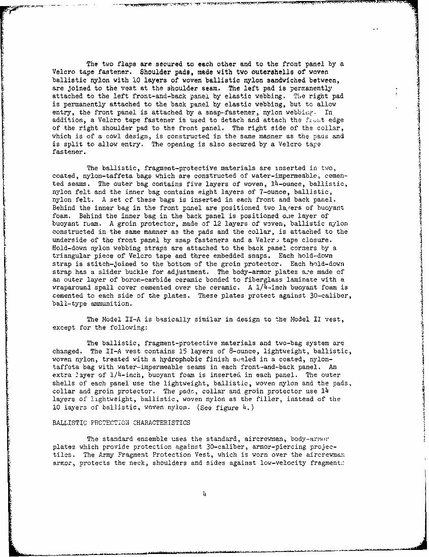
The two flaps are secured to each other and to the front panel by aVelcro tape fastener. Shoulder pads, made with two outershells of wovenballistic nylon with 10 layers of woven ballistic nylon sandwiched between,are joined to the vest at the shoulder seam. The left pad is permanentlyattached to the left front-and-back panel by elastic webbing. Tile right padis permanently attached to the back panel by elastic webbing, but to allowentry, the front panel is attached by a snap-fastener, nylon webbiiq'. Inaddition, a Velcro tape fastener is used to detach and attach the fLz,t edgeof the right shoulder pad to the front panel. The right side of the collar,which is of a cowl design, is constructed in the same manner as the Dads andis split to allow entry. The opening is also secured by a Velcro tapefastener.
The ballistic, fragment-protective materials are inserted in two,coated, nylon-taffeta bags which are constructed of water-impermeable, cemen-ted seams. The outer bag contains five layers of woven, ±4-ounce, ballistic,nylon felt and the inner bag contains eight layers of 7-ounce, ballistic,nylon felt. A set of these bags is inserted in each front and back panel.Behind the inner bag in the front panel are positioned two larers of buoyantfoam. Behind the inner bag in the back panel is positioned o.ie layer ofbuoyant roam. A groin protector, made of 12 layers of woven, ballistic nylonconstructed in the same manner as the pads and the collar, is attached to theunderside of the front panel by snap fasteners and a Velcr) tape closure.Hold-down nylon webbing straps are attached to the back panel corners by a
triangular piece of Velcro tape and three embedded snaps. Each hold-downstrap is stitch-joined to the bottom of the groin protector. Each hold-downstrap has a slider buckle for adjustment. The body-armor plates a^e made ofan outer layer of boron-carbide ceramic bonded to fiberglass laminate with awraparound spall cover cemented over the ceramic. A 1/4-inch buoyant foam iscemented to each side of the plates. These plates protect against 30-caliber,ball-type ammunition.
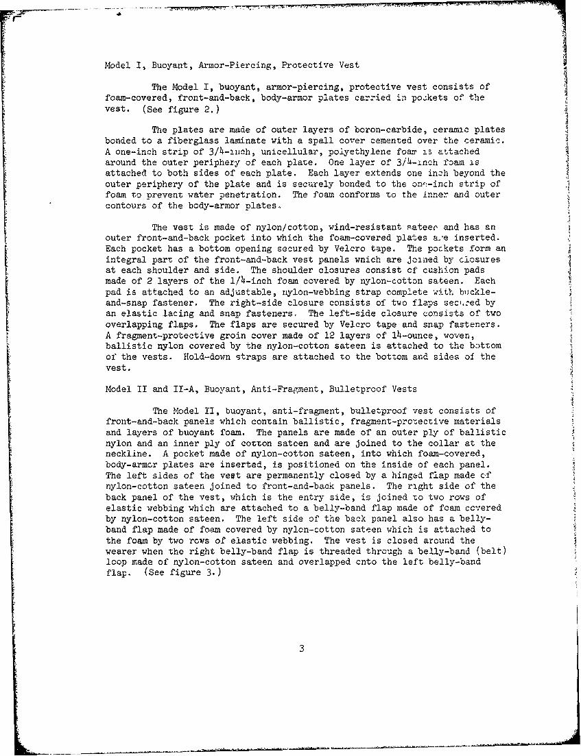
The Model II-A is basically similar in design to the Model II vest,except for the following:
The ballistic, fragment-protective materials and two-bag system arechanged. The II-A vest contains 15 layers of 8-ounce, lightweight, ballistic,woven nylon, treated with a hydrophobic finish s,:aled in a coated, nylon-taffeta bag with water-impermeable seams in each front-and-back panel. Anextra 2ayer of 1/h-inch, buoyant foam is inserted in each panel. The outershells of each panel use the lightweight, ballistic, woven nylon and the pads,collar and groin protector. The pad&, collar and groin protector use 14layers of lightweight, ballistic, woven nylon as the filler, instead of the10 layers of ballistic, woven nylon. (See figure 4.)
BALLISTIC PROTECTION CHARACTERISTICS
The standard ensemble uses the standard, aircrewnan, body-arr(',mplates which provide protection against 30-caliber, armor-piercing projec-tiles. The Army Fragment Frotection Vest, which is worn over the aircrewmanarmor, protects the neck, shoulders and sides against low-velocity fragment::
4
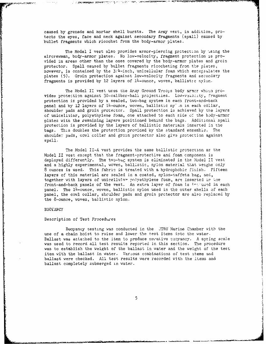
caused by grenade and mortar shell bursts. The Army vest, in addition, pro-tects the eyes, face and neck against secondary fragments (spall) caused bybullet fragments which ricochet from the body-armor plates.
The Model I vest also provides armor-piercing protection by using theaircrewman, body-armor plates. No low-velocity, fragment protection is pro-
vided in areas other than the ones covered by the body-armor plates and groinprotector. Spall caused by bullet fragments ricocheting from the plates,however, is contained by the 3/ 4 -inch, unicellular foam which en'.s"lae'es theplates (5). Groin protection against low-velocity fragments and sezondaryfragments is provided by 12 layers of 14 -ounce, woven, ballistic nylon.
The Model II vest uses the Army Ground Troocs body armor whanh pro-vides protection against 30-caliber-ball projectiles. Low-vý±oc:ty, fragmentprotection is provided by a sealed, two-bag system in each front-and-backpanel and by 12 layers of 14-ounce, woven, ballistic ny ,n in each collar,shoulder pads and groin protector. Spall protection is achieved by the layersof unicellualar, polyethylene foam, one attached to each side o' the body-armorplates with the remaining layers positioned behind the bags. Additional spallprotection is provided by the layers of ballistic materials inserted in thebags. This doubles the protection provided by the standard ensemble. Theshoulder pads, cowl collar and groin protector also give protection against
spall.
The Model II-A vest provides the same ballistic protection as theModel II vest except that the fragment-protective and foam component isdeployed differently. The two-b4G system is eliminated in the Model II vestand a highly experimental, woven, ballistic, nylon material that weighs only8 ounces is used. This fabric is treated with a hydrophobic finish. Fifteenlayers of this material are sealed in a coated, nylon-taffeta bag, and,together with layers of unicellu½a- polyethylene foam, are inserted ir hnefront-and-back panels of the vest. An extra layer of foam is i- ud&d in eachpanel. The 14-ounce, woven, ballistic nylon used in the outer shells of eachpanel, the cowl collar, shoulder pads and groin prctector are also replaced bythe 8-ounce, woven, ballistic nylon.
BUOYALNCY
Description of Test Procedures
Buoyancy testing was conducted in the 2TRU Marine Chamber with theuse of a chain hoist to raise and lower the test items into the water.Ballast was attached to the item to produce nerative -uoyancy. A spring scalewas used to record all test results renorted in this section. The procedurewas to establish the weight of the ballast in water and the weight of the testitem with the ballast in water. Various combinations of test items andballast were checked. All test results were recorded with the items andballast completely submerged in water.
5
Test Results
Table I is a tabulation-of test results using the above test pro-cedures to determine the relative buoyancy of the standard ensemble and theModel I, II and II-A vests.
4A
6a
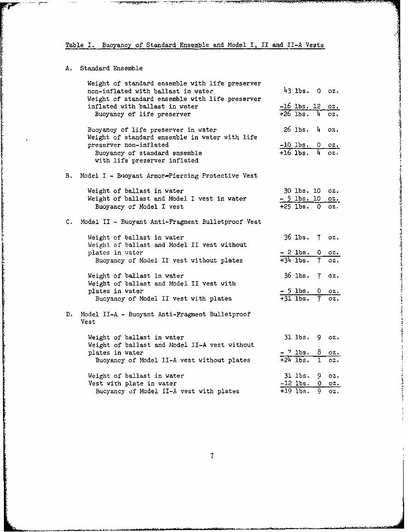
Table I. Buoyancy of Standard Ensemble and Model I, II and II-A Vests
A. Standard Ensemble
Weight of standard ensemble with life preservernon-inflated with ballast in water 43 lbs. 0 oz.Weight of standard ensemble with life preserverinflated with ballast in water -16 lbs. 12 oz.
Buoyancy of life preserver +26 lbs. 4 oz.
Buoyancy of life preserver in water 26 lbs. 4 oz.Weight of standard ensemble in water with lifepreserver non-inflated -10 lbs. 0 oz.
Buoyancy of standard ensemble +16 lbs. 4 oz.with life preserver inflated
B. Model I - Buoyant Armor-Piercing Protective Vest
Weight of ballast in water 30 lbs. 10 oz.Weight of ballast and Model I vest in water - 5 lbs. 10 oz.
Buoyancy of Model I vest +25 lbs. 0 oz,
C. Model II - Buoyant Anti-Fragment Bulletproof Vest
Weight of ballast in water 36 lbs. 7 oz.Weight of ballast and Model II vest withoutolates in water - 2 lbs. 0 oz.
Buoyancy of Model II vest without plates +34 lbs. 7 oz.
Weight of ballast in water 36 lbs. 7 oz.Weight of ballast and Model II vest withplates in water - 5 lbs. 0 oz.
Bucyancy of Model II vest with plates +31 lbs. 7 oz.
D. Model II-A - Buoyant Anti-Fragment BulletproofVest
Weight of ballast in water 31 lbs. 9 oz.Weight of ballast and Model II-A vest withoutplates in water - 7 lbs. 8 oz.
Buoyancy of Model II-A vest without plates +24 lbs. 1 oz.
Weight of ballast in water 31 lbs. 9 oz.Vest with plate in water -12 lbs. 0 oz.
Buoyancy of Model II-A vest with plates +19 lbs. 9 oz.
7
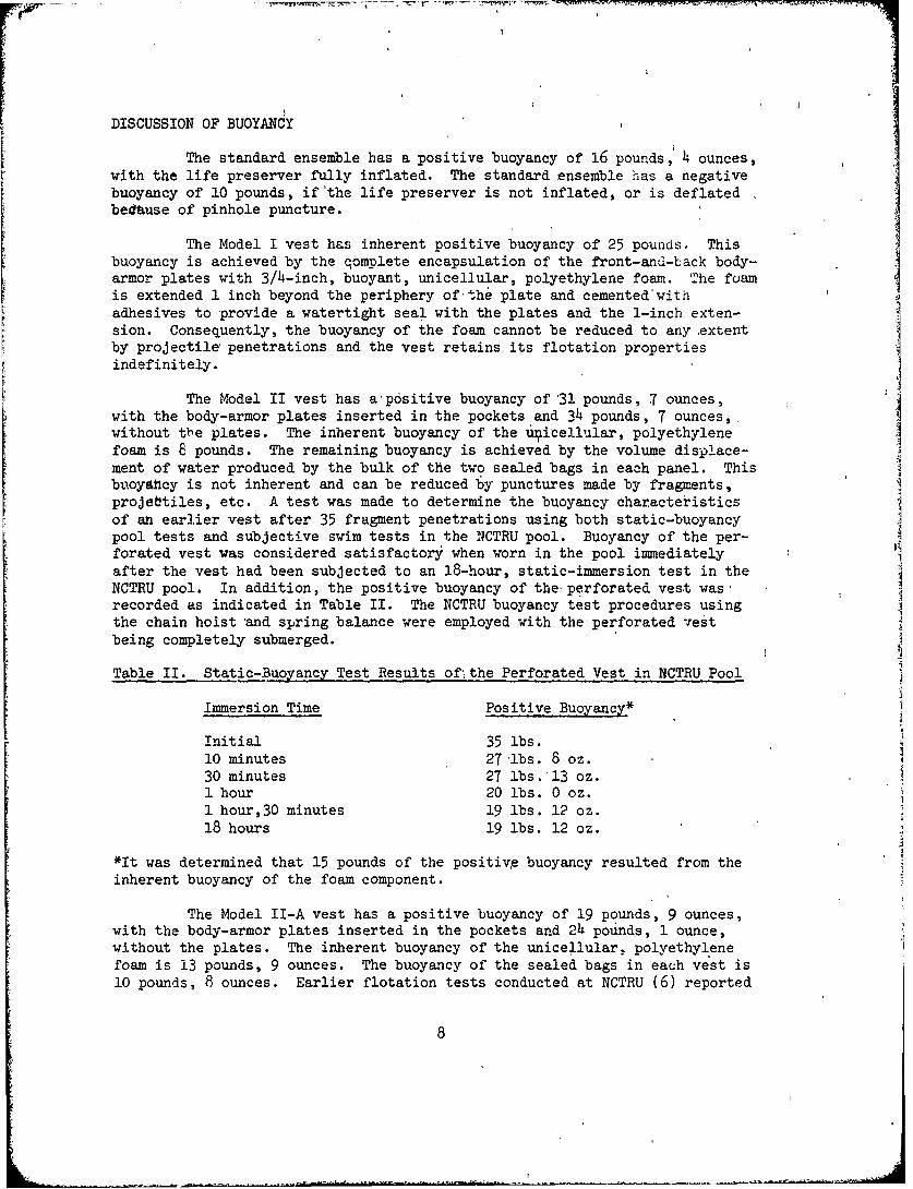
DISCUSSION OF BUOYANCY
The standard ensemble has a positive buoyancy of 16 pounds, 4 ounces,with the life preserver fully inflated. The standard ensemble has a negativebuoyancy of 10 pounds, if'the life preserver is not inflated, or is deflatedbedause of pinhole puncture.
The Model I vest has inherent positive buoyancy of 25 pounds. Thisbuoyancy is achieved by the qomplete encapsulation of the front-and-back body-armor plates with 3/4-inch, buoyant, unicellular, polyethylene foam. The fomunis extended 1 inch beyond the periphery of the plate and cemented'withadhesives to provide a watertight seal with the plates and the 1-inch exten-sion. Consequently, the buoyancy of the foam cannot be reduced to any extentby projectile penetrations and the vest retains its flotation propertiesindefinitely.
The Model II vest has a p6sitive buoyancy of 31 pounds, 7 ounces,with the body-armor plates inserted in the pockets and 34 pounds, 7 ounces,,without the plates. The inherent buoyancy of the 4iicellular, polyethylenefoam is 8 pounds. The remaining buoyancy is achieved by the volume displace-ment of water produced by the bulk of the two sealed bags in each panel. Thisbuoyatcy is not inherent and can be reduced by punctures made by fragments,projebtiles, etc. A test was made to determine the buoyancy characteristicsof an earlier vest after 35 fragment penetrations using both static-buoyancypool tests and subjective swim tests in the NCTRU pool. Buoyancy of the per-forated vest was considered satisfactory when worn in the pool immediatelyafter the vest had been subjected to an 18-hour, static-immersion test in theNCTRU pool. In addition, the positive buoyancy of the perforated vest was-recorded as indicated in Table II. The NCTRU buoyancy test procedures usingthe chain hoist and spring balance were employed with the perforated vestbeing completely submerged.
Table II. Static-Buoyancy Test Results of* the Perforated Vest in NCTRU Pool
Immersion Time Positive Buoyancy*
Initial 35 lbs.10 minutes 27 lbs. 8 oz.30 minutes 27 lbs. 13 oz.1 hour 20 lbs. 0 oz.1 hour,30 minutes 19 lbs. 12 oz.18 hours 19 lbs. 12 oz.
*It was determined that 15 pounds of the positive buoyancy resulted from the
inherent buoyancy of the foam component.
The Model II-A vest has a positive buoyancy of 19 pounds, 9 ounces,with the body-armor plates inserted in the pockets and 24 pounds, 1 ounce,without the plates. The inherent buoyancy of the unicellular, polyethylenefoam is 13 pounds, 9 ounces. The buoyancy of the sealed bags in each vest is10 pounds, 8 ounces. Earlier flotation tests conducted at NCTRU (6) reported
8
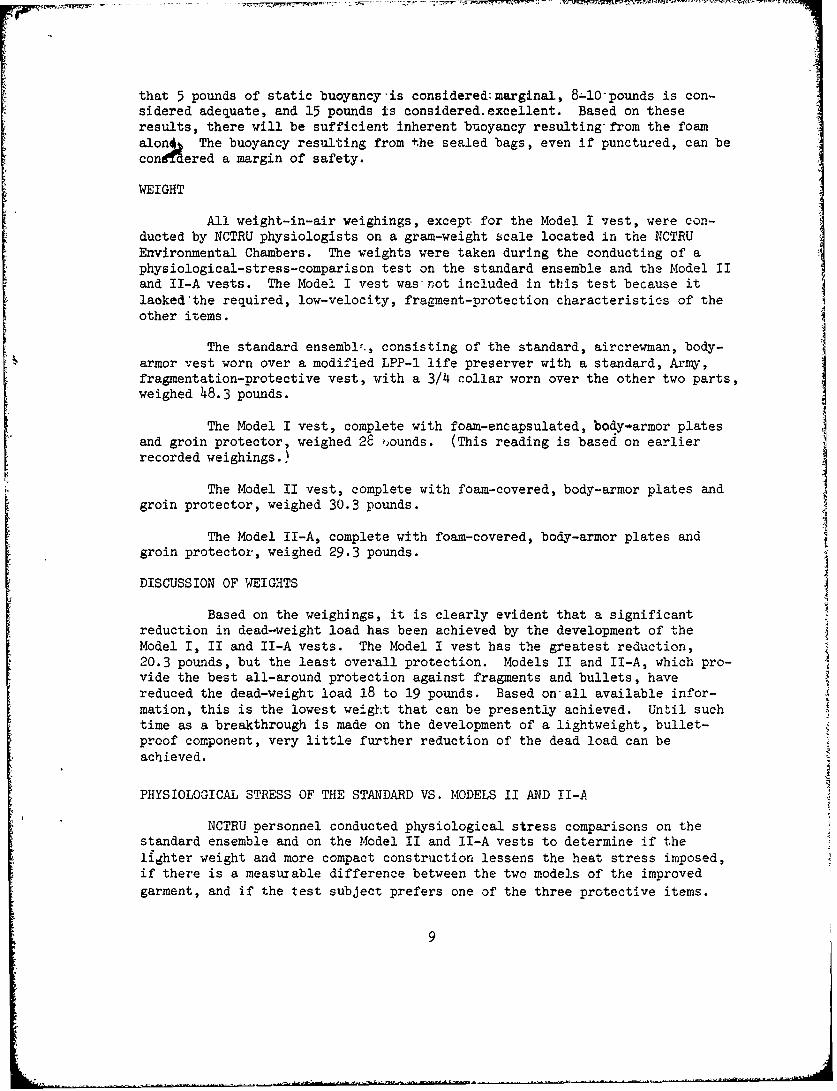
that 5 pounds of static buoyancy is considered:marginal, 8-10 pounds is con-sidered adequate, and 15 pounds is considered.excellent. Based on theseresults, there will be sufficient inherent buoyancy resulting from the foamalon4 The buoyancy resulting from the sealed bags, even if punctured, can beconffdered a margin of safety.
WEIGHT
All weight-in-air weighings, except for the Model I vest, were con-ducted by NCTRU physiologists on a gram-weight scale located in the NCTRUEnvironmental Chambers. The weights were taken during the conducting of aphysiological-stress-comparison test on the standard ensemble and the Model IIand II-A vests. The Model I vest was-not included in this test because itlaoked the required, low-velocity, fragment-protection characteristics of theother items.
The standard ensembl1., consisting of the standard, aircrewman, body-armor vest worn over a modified LPP-1 life preserver with a standard, Army,fragmentation-protective vest, with a 3/4 collar worn over the other two parts,weighed 48.3 pounds.
The Model I vest, complete with foam-encapsulated, body-armor platesand groin protector, weighed 28 )ounds. (This reading is based on earlierrecorded weighings.)
The Model II vest, complete with foam-covered, body-armor plates andgroin protector, weighed 30.3 pounds.
The Model II-A, complete with foam-covered, body-armor plates and
groin protector, weighed 29.3 pounds.
DISCUSSION OF WEIGHTS
Based on the weighings, it is clearly evident that a significantreduction in dead-weight load has been achieved by the development of theModel I, II and II-A vests. The Model I vest has the greatest reduction,20.3 pounds, but the least overall protection. Models II and II-A, which pro-vide the best all-around protection against fragments and bullets, havereduced the dead-weight load 18 to 19 pounds. Based on-all available infor-mation, this is the lowest weight that can be presently achieved. Until suchtime as a breakthrough is made on the development of a lightweight, bullet-proof component, very little further reduction of the dead load can beachieved.
PHYSIOLOGICAL STRESS OF THE STANDARD VS. MODELS II AND II-A
NCTRU personnel conducted physiological stress comparisons on thestandard ensemble and on the Model II and II-A vests to determine if thelighter weight and more compact construction lessens the heat stress imposed,if there is a measurable difference between the two models of the improvedgarment, and if the test subject prefers one of the three protective items.
9
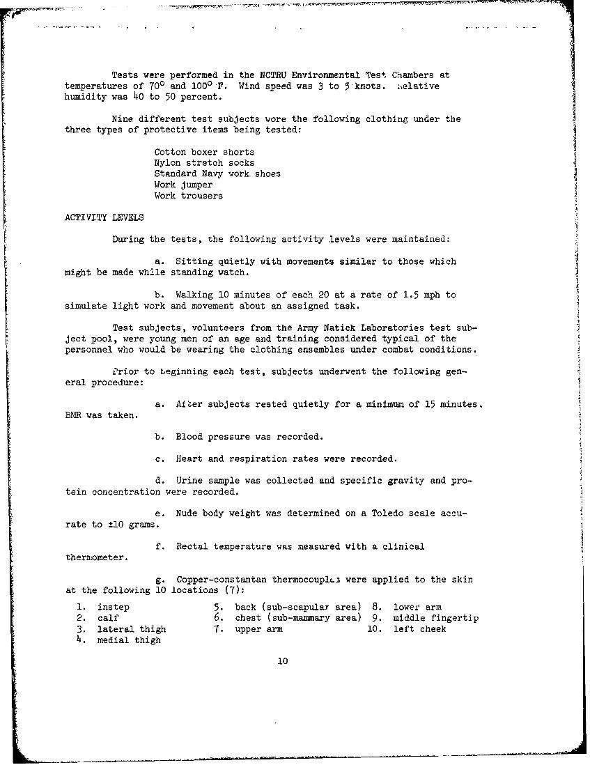
Tests were performed in the NCTRU Environmental Test Chambers attemperatures of 700 and 1000 F. Wind speed was 3 to 5-knots. tielativehumidity was 40 to 50 percent.
Nine different test subjects wore the following clothing- under thethree types of protective items being tested:
Cotton boxer shortsNylon stretch socksStandard Navy work shoesWork jumperWork trousers
ACTIVITY LEVELS
During the tests, the following activity levels were maintained:
a. Sitting quietly with movements similar to those which
might be made while standing watch.
b. Walking 10 minutes of each 20 at a rate of 1.5 mph tosimulate light work and movement about an assigned task.
Test subjects, volunteers from the Army Natick Laboratories test sub-ject pool, were young men of an age and training considered typical of thepersonnel who would be wearing the clothing ensembles under combat conditions.
Prior to beginning each test, subjects underwent the following gen-eral procedure:
a. AIýer subjects rested quietly for a minimum of 15 minutes,
BMR was taken.
b. Blood pressure was recorded.
c. Heart and respiration rates were recorded.
d. Urine sample was collected and specific gravity and pro-tein concentration were recorded.
e. Nude body weight was determined on a Toledo scale accu-rate to ±10 grams.
f. Rectal temperature was measured with a clinicalthermometer.
g. Copper-constantan thermocouplf• were applied to the skinat the following 10 locations (7):
1. instep 5. back (sub-scapular area) 8. lower arm2. calf 6. chest (sub-mammary area) 9. middle fingertip3. lateral thigh 7. upper arm 10. left cheek4. medial thigh
10
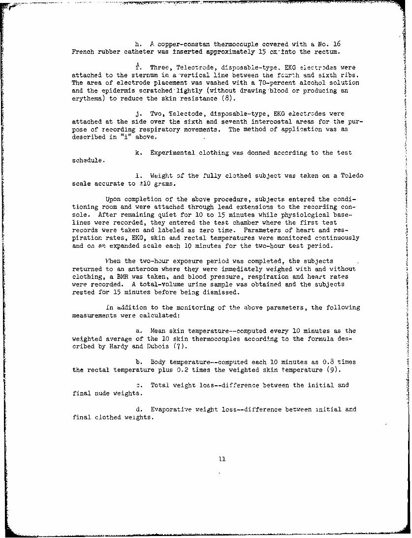
h. A copper-constan thermocouple covered with a No. 16French rubber catheter was inserted approximately 15 cz-into the rectum.
i•. Three, Telectrode, disposable-type. EKG electr~des were
attached to the sternum in a'vertical line between the fourth and sixth ribs.The area of electrode placement was washed with a 70-percent alcohol solutionand the epidermis scratched-lightly (without drawing-blood or producing anerythema) to reduce the skin resistance (8).
j. Two, Telectode, disposable-type, EKG electrcodes wereattached at the side over the sixth and seventh intercostal areas for the pur-pose of recording respiratory movements. The method of application was asdescribed in "i" above,
k. Experimental clothing was donned according to the testschedule.
1. Weight of the fully clothed subject was taken on a Toledoscale accurate to ±10 grams.
Upon completion of the above procedure, subjects entered the condi-tioning room and were attached through lead extensions to the recording con-sole. After remaining quiet for 10 to 15 minutes while physiological base-lines were recorded, they entered the test chamber where the first testrecords were taken and labeled as zero time. Parameters of heart and res-piration rates, EKG, skin and rectal temperatures were monitored continuouslyand on an expanded scale each 10 minutes for the two-hour test period.
When the two-hour exposure period was completed, the subjectsreturned to an anteroom where they were immediately weighed with and withoutclothing, a BMR was taken, and blood pres3ure, respiration and heart rateswere recorded. A total-volume urine sample was obtained and the subjectsrested for 15 minutes before being dismissed.
In Kddition to the monitoring of the above parameters, the followingmeasurements were calculated:
a. Mean skin temperature--computed every 10 minutes as theweighted average of the J.0 skin thermocouples according to the formula des-cribed by Hardy and Dubois (7).
b. Body temperature--computed each 10 minutes as 0.8 timesthe rectal temperature plus 0.2 times the weighted skin temperature (9).
c. Total weight loss--difference between the initial andfinal nude weights.
d. Evaporative weight loss--difference between initial andfinal clothed weights.
11
/i
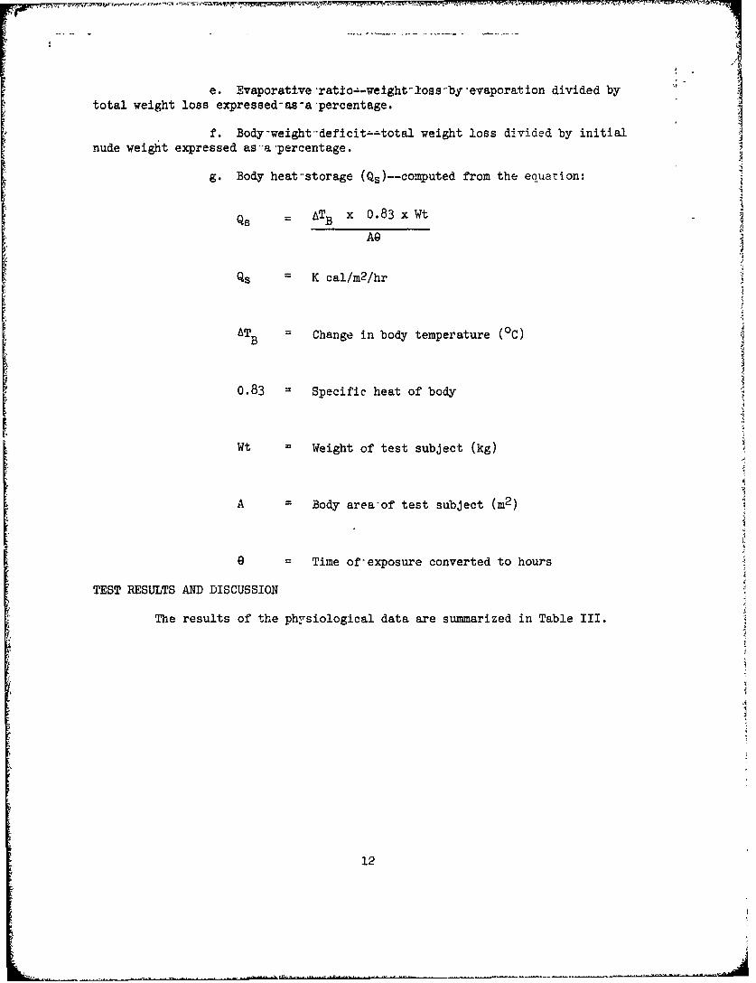
e. Evaporative-rat±o-.-weight-loss-by-evaporation divided bytotal weight loss expressed-as-a-percentage.
f. Body-weight-deficitz-total weight loss divided by initialnude weight expressed as'a-percentage.
g. Body heat*storage (Qs)--computed from the equation:
Qs = ATB x 0.83 x Wt
AG
Qs = K cal/m2 /hr
ATB Change in body temperature (0c)
0.83 Specific heat of body
Wt Weight of test subject (kg)
A Body area'of test subject (m2 )
9 = Time of-exposure converted to hours
TEST RESULTS AND DISCUSSION
The results of the physiological data are summarized in Table III.
12

H M U- I \
-*-'.* (y~k Oltc0 0 0I
(V ~~ 1..\ .t .ar.C.q o: -; d (Y 0 (I 0io; )C)C 4 o0 0 001
I- Z) r.CD X a\
+1~ 'E-1~. E-1I(4
PL4~~~~~sIZ E- (NJQC 0- _z C)"",C-0 cý\
t"'0 \0 H f f L 40u'
oo C; 0 I)0 r C 0- 01oo oc cjc QL O C'jC- ZC) '7 - J,\ c \C. -: C\J ('.3 o c) "
+1
004~I C) UN40\ 0,L :-t*0* * .1 . -,"0 Cfl 00 0C, r- -4 0 ' t-1 ý \
!0t It f o ot z i w, 'z to ti -'.r,'C' tz t"' IH o br. I: fI- C: r I 13 - -C . c
I-I I I ; "1 , 11 r
I- '- .: - + -1 -
U))
0 0 0 L [C C, 0 iI 10 C) 'Q)0 0l 0 )
Ii: I (\a 0-
coo
xrmm
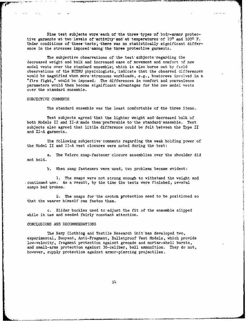
Nine test subjects wore -each of the three types of body-armor protec-tive garments at two levels of-activity-and at temperatures-of 700 and 1000 F.Under conditions of these-tests;-there was no statistically significant differ-ence in the stresses imposed'among~thethree protective garments.
The subjective observations of the test subjectsregarding thedecreased weight and bulk and increased ease of movement and comfort of newmodel vests over the standard ensemble; which is also borne out by fieldobservations of the NCTRU physiologists, indicate that the observed differenceswould be magnified when more--strenuous workloads, e.g., boatcrews involved in a"fire fight," would be imposed; The differences in comfort and convenienceparameters would then become significant advantages for the new model vestsoer the standard ensemble.
SUBJECTIVE COMMENTS
The standard ensemble was the least comfortable of the three items.
Test subjects agreed- that the lighter weight and-decreased bulk ofboth Models II and II-Akmade them-preferable to-the standard-ensemble. Testsubjects also agreed that little difference could be felt between the Type IIand II-A garments.
The following subjective- comments regarding the weak holding power ofthe Model II and II-A vest closures were noted during the test:
a. The Velcro snap-fastener closure assemblies over the shoulder didnot hold.
b. When snap fasteners were-used' two problems became evident:
1. The snaps were not strong enough to withstand the weight and.continued use. As a result, by the time the tests were finished, severalsnaps had broken.
2. The-snaps for'the crotch protection need to-be positioned sothat the wearer himself can fasten them.
c. Slider buckles used to-adjust the fit of the ensemble slippedwhile in use and needed fairly-constant attention.
CONCLUSIONS AND RECOMMENDATIONS
The Navy Clothing and Textile Research Unit-has developed two,experimental, Buoyant, Anti-Fragment, Bulletproof Vest Models, which providelow-velocity, fragment protection against grenade and-mortar-shell bursts,and small-arms protection against 30-caliber, ball ammunition. They do not,however, supply protection against armor-piercing projectiles.
14
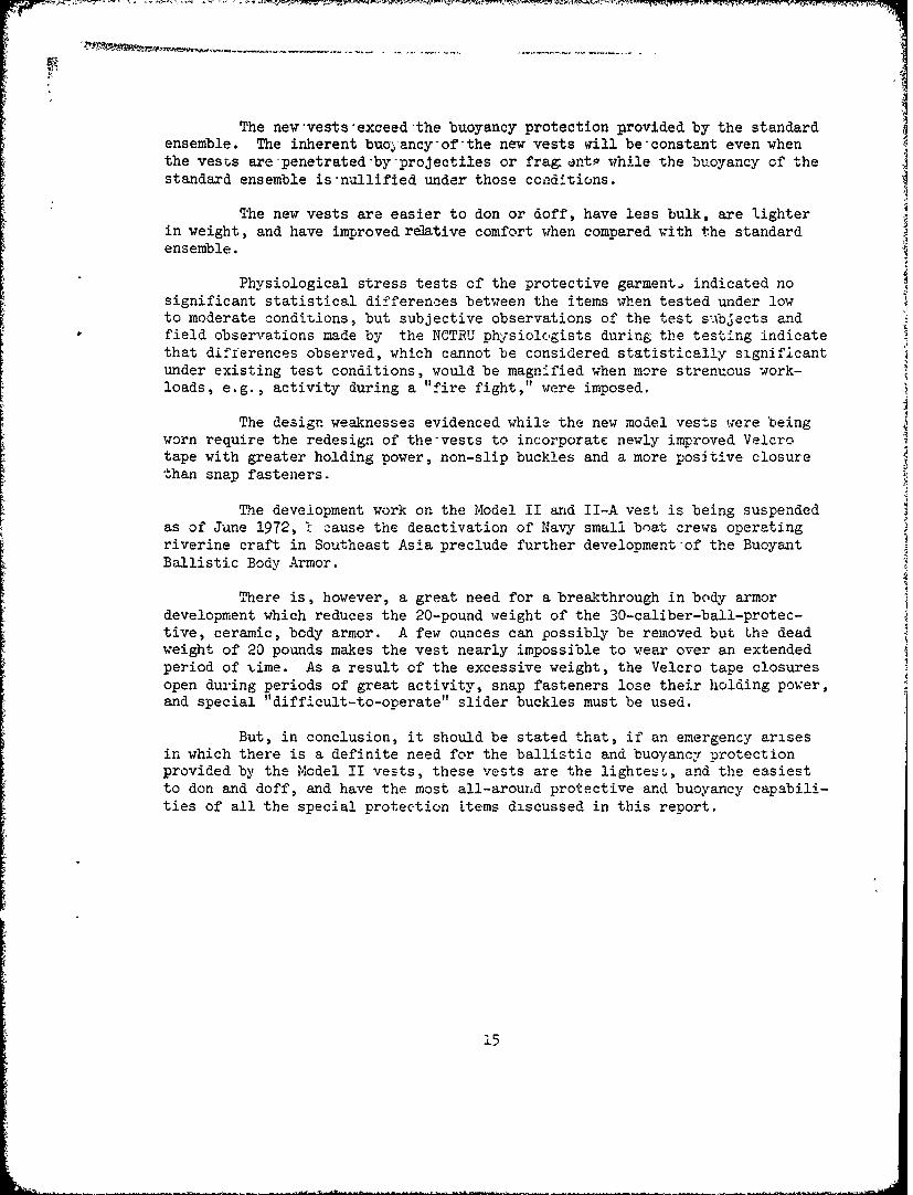
The new'vests-exceed-the buoyancy protection provided by the standardensemble. The inherent buoyancy-ofthe new vests will be'constant even whenthe vests are-penetrated-by-projectiles or frag antp while the buoyancy of thestandard ensemble is'nullified under those conditions.
The new vests are easier to don or doff, have less bulk, are lighterin weight, and have improved relative comfort when compared vith the standardensemble.
Physiological stress tests of the protective garment, indicated no
significant statistical differences between the items when tested under lowto moderate conditions, but subjective observations of the test subjects andfield observations made by the NCTRU physiologists during the testing indicatethat differences observed, which cannot be considered statistically significantunder existing test conditions, would be magnified when more strenuous work-loads, e.g., activity during a "fire fight," were imposed.
The design weaknesses evidenced while the new model vests were beingworn require the redesign of the-vests to incorporate newly improved Velcrotape with greater holding power, non-slip buckles and a more positive closurethan snap fasteners.
The development work on the Model II and II-A vest is being suspendedas of June 1972, 1 cause the deactivation of Navy small boat crews operatingriverine craft in Southeast Asia preclude further development-of the BuoyantBallistic Body Armor.
There is, however, a great need for a breakthrough in body armordevelopment which reduces the 20-pound weight of the 30-caliber-ball-protec-tive, ceramic, body armor. A few ounces can possibly be removed but the deadweight of 20 pounds makes the vest nearly impossible to wear over an extendedperiod of time. As a result of the excessive weight, the Velcro tape closuresopen during periods of great activity, snap fasteners lose their holding power,and special "difficult-to-operate" slider buckles must be used.
But, in conclusion, it should be stated that, if an emergency arisesin which there is a definite need for the ballistic and buoyancy protectionprovided by the Model II vests, these vests are the lighre!., and the easiestto don and doff, and have the most all-around protective and buoyancy capabili-ties of all the special protection items discussed in this report.
15
.&.ic�.iw � ,w'. v�. .,. p � �
- ,-- - - -� - ii
r 'II
.1
J
II
APPEI�IX A;� ILLUSTRATIONS
-5
'A
A-i
/4
T M9
Figure 1. Front and Side Views of Standard Ensemble.
|j
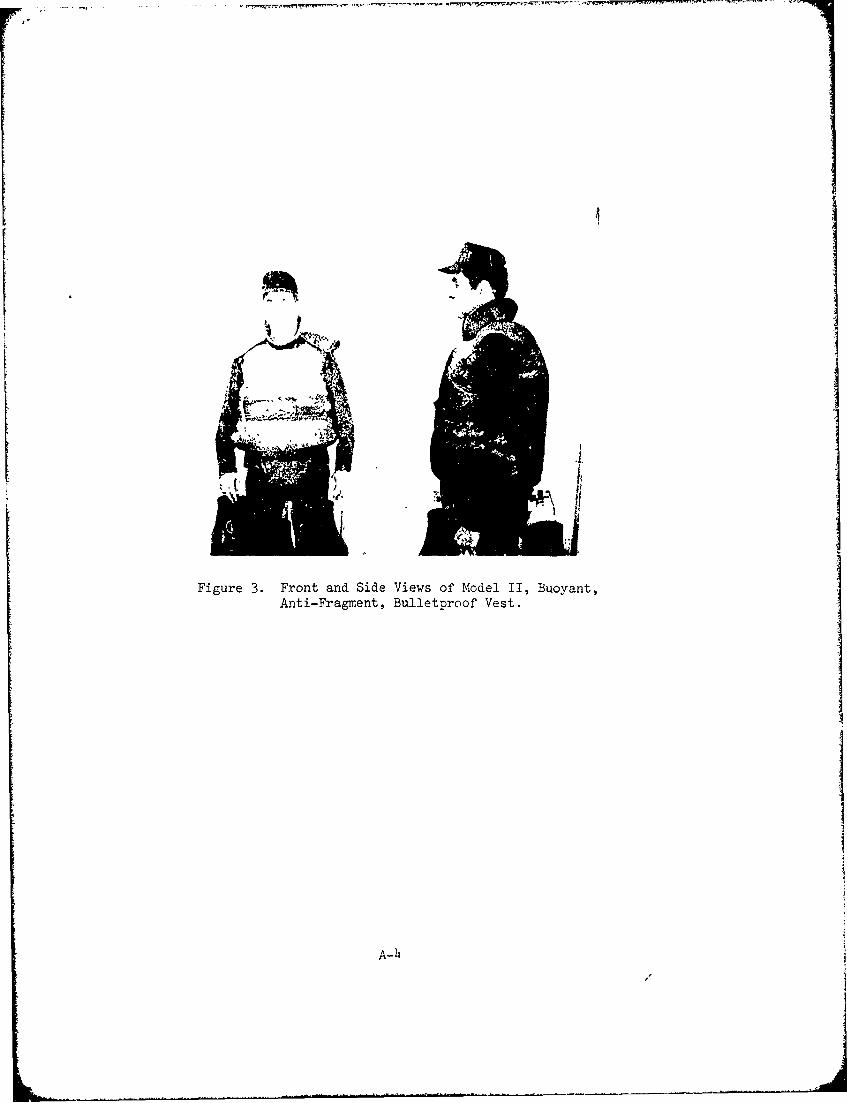
Figure 3. Front and Side Views of Model II, Buoyant,Anti-Fragment, Bulletproof Vest.
A-4
I-r - m- r
n-cm- -
-S_-Sm.
t
a-
t
- I t
__________________________________________________
a
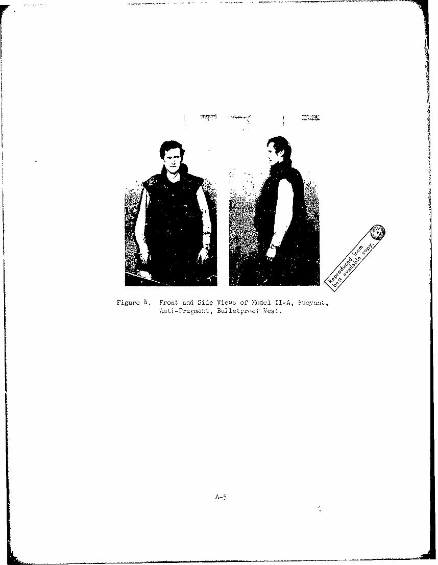
Fil-ure 11 Front and Side Views of %,.odei I.-,, 1-uoyamlt,,ai]ti-Fragment, Bul let-proof Vest.
A-5

Appendix B. References
1. Commander, Naval Ordnance Systems Command letter, ORD:UV31l:RDG, of26 July 1967.
2. Chief, Naval Research and Development Unit - Vietnam !ec. 3910, Ser 41,of February 1968.
3. Chief, Naval Research and Development Unit - Vietnam letter 3900,Ser 107, of 10 August 1967.
4. Commander, Naval Force - Vietnam letter 3910, Ser 810, of 9 March 1968.
5. Learned, A.W. III, An Investigation of Ballistic Characteristics of the
Navy Buoyant Armor Piercing Protective Body Armor, Contract N00298-68-C-0192, Proj. TF-015-2203-012, Norton Company, Worcester, Massachusetts,January 1968.
6. Weinstock, L., Buoyant and Flotation Characteristics of Buoyant FoamInsulated Cold Weather Clothing; NCTRU Technical Report No. 79, June 1965.
7. Hardy, J., and Dubois, E., "Basal Metabolism Radiation, Convection andEvaporization at Temperatures 220 and 350 C," Journal of Nutrition,15:461 (1938).
8. Byers, B., Biopotential Skin Electrode Instruction Manual, Spinco DivisionTechnical Publications Department; Cat. OTB 002, Dee Tozer Advertising,Redwood City, California.
9. Stolwijk, J. A., Hardy, J. D., "Partitional Calorimetric Studies ofResponses of Man to Thermal Transients," Journal of Applied Physiology,21:967 (1966).
B-1
Department of the Nav
Commander, Naval Supply Systems Command (OlAl), Navy Department,Washington, D. C. 20360 (3)
Chief of Naval Operations (OP-721:OP7TX), NavyDepartment,Washington, D. C. 20360 ,1)
Commander, Naval Air SystemsCommand (Code AIR-53,l), Fiavy] Departmsnt, ,Wasbington, D, C0 20360 (i)
Commander, Naval Ships Systems Commandi Navy Department,Washington, D. C. 20360 (1)
Commaen.ing Officer, Naval Air Development Center, Aero Space CrewEquipment Department. Johnsville, Warminster, PA 18974 (1)
Commanding Officer and Director, Naval Research and Development Laboratory,Applied Sciences Department, Annapolis, Maryland 21402 (1)
Commander, Naval Ships Engineering Center,.Center Building, Prince GeorgesPlaza, Hyattsville, Maryland 20782 (Attn: Code 6134) (1)
Chief, Damage Control Section, Naval Ships Engineering Center, CenterBuilding, Prince Georges Plaza, Hyattsville, Maryland 20782(Attn: Code 6105) (1)
Commanding Officer, Office of Naval Research Branch Office, 495 SumaerStreet, Boston, MA 02210 (Attn: Patent Council) (1)
Commandar.t of the Marine Corps (Code A0hd), Headquarters, U.s. MarineCorps, Navy Department, Washington, D. C. 20360 (1)
Chief, Bureau of M4edicine and S~rgery, Navy Department (Code 71),Washington, D. C 20390 (I)
Commander, Naval Facilities Engineering Comnand, Department of the Navy,Washington, D. C. 20390 (1)
Chipf of Naval Material (MAT 034D), Department of the Navy,Washington, D. C. 20360 (1)
Director, Naval Research Laboratory, Washington, D. C. 20390(Attn: Code 6130:DDW) (1)
Commander, Naval Weapons Laboratory, Dahlgren'o VA 22448(Attn: Code FCV) (1)
Commanding Officer, Naval Explosive Oidnance Disposal Facility,Indian Head, Maryland 20640 (1)
Commander, Naval Coastal Systems Laboratory, Panama City, Florida 32401(Attn: Technical Library) (1)
Comman&ing Officer, Naval Medical Research institute, National NavalMedical Center, Bethesda, RD 20014 (Attn: Chief, Physiology ResesrchGroirp) (i)
Officer in Charge, Nav,,a Submarine Medical. Research Laboratory, NavalSubmarine Med-ca.o. Center, Groton, Connecticut 06340 11)
Officer in Chaj-ge, Nia7,-y Expevimental Diving Unit, Washington Navy Yard,Washington, Y). C. 20390 (1)
Supervisor of DJv-.,g (00C), Naval Ships Systems. Command,Washington, D. C. 2036o (W)
/ r
Department of Defense
Commander, Defense Personnel Support Center, 2800 South 20th Street,Philadelphia, Penrsylvania 19101 (Attn: Catalog and StandardizationOffice) (6)
Director, Defense Documentation Center (TIMA), Cameron Station,Alexandria, Virginia 22314 (12)
Department of the Army
Commanding General, U.S. Army Natick Laboratories, Natick, MA 01760(Attn: Technical Library) (2)
Commanding General, U.S. Army Natick Laboratories, Natick, MA 01760(Attn: Clothing and Organic Materials Division) (1)
Commanding General, U.S. Army Natick Laboratories, Natick, MA 01760(Attn: Advanced Projects Branch of Clothing and Organic MaterialsDivision) (1)
Commanding General, U.S. Army Material Command, Washington, D. C. 20315(Attn: Director for Research, Development and Engineering) (1)
Department of the Air Force
Director, Crew and Age Subsystems Engineering, Aeronautical SystemLcDivision, Wright-Patterson Air Force Base, Ohio 45433 (Attn: ENCU--Clothing Division) (1)
Others
Munitions Research Member, BDSW (R&D), British Embassy, 3100 MassachusettsAvenue, N.W., Washington, D. C. 20008 (1)
Chief, Canadian Defense Research Staff, 2450 Massachusetts Avenue, N.W.,Washington, D. C. 20008 (1)
Chief of the Defense Staff, Canadian Forces Headquarters, Department ofNational Defense, Ottawa (KIA 0K2), Ontario, Canada (Attn: DCGE) (1)
Director-General, Defense Research Establishment Ottawa, Shirley Bay,Ottawa, 4, Ontario, Canada (Attn: Technical Library) (1)
U.S. Department of Labor, Occupational Safety and Health Administration,Office of Standards, Railway Labor Building, Room 305, 400 First Street,N.W., Washington, D. C. 20210 (Attn: Chief, Division of MaritimeStandards) (1)
2