Embed Size (px)
Citation preview

CNC TURNINGMTAB CONTROL PROGRAMMING MANUAL
[1]
CNC TURNING PROGRAMMINGMANUAL
BYMTAB TECHNOLOGY CENTER PVT (LTD)
#133, Developed plots, Electrical & Electronics Industrial Estate, Chennai 96.Ph.: +91-44-43111114, Email id: [email protected]
Website: www.mtabtraining.com

[2]

[3]
1. PART PROGRAMMING FUNDAMENTALS:
The following are the basic steps which involved in the CNC procedure.
o Process planning
o Part programming
o Part program entry
o Proving part programs
o Program preparation methods
1.1 Process Planning:
The part programmer will often carry out the task of process planning. Process planning is
the procedure of deciding what operation are to be done on the component, in what order
and with what tooling and work holding facilities. Both the process planning and part
programming aspects of manufacturer occur after the detail drawings of a component have
been prepared. The following procedure maybe used as a guide to assist the programmer by
describing each step required in preparing the method of production.
Receive the part drawing from the part drawing information and check the suitability
of part to be machined against the machine capacity.
Determine a method to driving the component (Chuck type, chuck size, type of jaw,
collect size, face driver etc.) and the method of machining.
Determine the tooling required to suit the method of machining and utilize as much
as possible which are permanently in the turret set upon the machine.
Determine the order of machining and tooling stations
Determine the planned stop (Cycle interrupt procedure, incorporating block delete
codes) for checking dimensional sizes where required by operator.
Determine the cutting speed based on i) component material, method of driving,
rigidity of the component. ii) The tooling selected for roughing and finishing tool
holders with carbide drills, HSS drills and ceramics.
Determine the depth of cut and feed rate for roughing operation based on the
horsepower available for cutting and rigidity of the part.
[4]
Determine form surface finish requirements the cutter nose radius most suited for
finishing operations and determine feed rates.
Allocates tool offsets as required
Complete planning sheet
1.2 Part Programming:
After completing the planning sheet, draw the component showing the cutter paths.
Select a component datum and carryout the necessary calculations at slopes and
arcs.
Prepare tooling layout sheet showing tools to be used in the program and indicate
the station number for each tool.
Indicate the ordering code for each tool, grade and type of inserts to be used.
Write the part program according to the sequence of operations.
1.3 Part Program Entry:
The part program is prepared and then feed into the machine control unit (MCU) in order to
prepare a component of interest on machine tool. The input to the system can be done
through two ways.
o Manual Data Input
o Direct Numerical Input
1.3.1 Manual Data Input (MDI)
Complete part programs are entered into CNC control unit via the console keyboard. It is
suited only for relatively simple jobs the most common application for MDI is the editing of
part programs already resident in the controllers memory.
MDI concept is also called as “Conversational Programming” most of the CNC machines are
programmed via a question and answer technique whereby a resident of software program
asks the operator a series of questions. In response to the operators input, and by accessing
a pre-programmed data file in the computer control by
Select numerical values for use within machining calculations
[5]
Perform calculations to optimize machining conditions
Identify standard tools and coordinates
Calculate cutter paths and coordinates
Generate the part program to machine the component
1.3.2 Direct Numerical Control (DNC)
The process of transferring part programs into the memory of a CNC machine tool from a
host computer is called direct numerical control.
1.4 Proving Part Programs
It is a safe practice to check the programmed path for any interference between the tool
and the work before using the part program for production this process is known as proving
part program. This process is done in several ways as follow:
i) Visual Inspection:
It represents the methods of checking visually the program present in the memory of the
CNC machine. In this actual program is run and the program movements in all axes to be
checked along with ensuring the tool offset of cutter compensation features. This method
represents the least form of verification and should not be relied entirely.
ii) Single Step Execution:
Before running the part program it should be executed in a single step mode i.e., block by
block. During execution the spindle speed, feed rate override facilities are used to monitor
the axes movement easily. This operation maybe carried out with or without mounting the
component in the machine.
iii) Dry Run:
A dry run consists of running the part program in auto mode. During this, the component is
not inserted in the machine table and the cutting is done in air. The purpose of dry run is to
verify the programmed path of the tool under continuous operation and to check whether
the adequate clearance exist between clamping arrangement and other projections with the
setup. Feed rate override facilities are used to slow down the speed of program execution.
[6]
iv) Graphical Simulation:
A graphical simulation package emulates the machine tool and using computer graphics,
plots out the machine movement on a visual display unit (VDU) screen. Machine movement
often takes the form of a cutting tool shape moving around the screen according to the
programmed movements. When the tool shape passes over a shaded representation of the
component it erases that part of the finished component and any gross deviations from the
intended tool path can be observed any potential interference can be highlighted.

[7]
2. PART PROGRAMMING GEOMETRY:
2.1 Coordinate System for a CNC Lathe:
Machining of a workpiece by a CNC program requires a coordinate system to be applied to
the machine tool. As all machine tools have more than one slide, it is important that each
slide is identified individually. There are three planes in which movement can take place.
Each place is assigned a letter and is referred as an axis,
o Longitudinal plane (AXIS X)
o Transverse plane (AXIS Z)
The two axis is identified by the upper case X and Z and the direction of movement along
each axis is specified in plus (+) or minus (-) and the Z axis is always parallel to the main
spindle of the machine, as shown in the below figure.
The coordinate system for designating the axes is the conventional ‘Right hand coordinate
system’ as shown in figure. A labeling of the axes is a right hand coordinate system
whenever the fingers of the right hand are aligned with the positive X axis and are then
rotated (through the smaller angle) toward the positive Y axis then the thumb of the right
hand points in the direction of the positive Z axis. Otherwise, the orientation is a ‘Left Hand
coordinate system’.
[10]
The right hand coordinate system is also known as ‘Clockwise rotating coordinate system’.
The reason for this is the sequence of the axis definitions. If the X axis is rotating in the
direction of the Y axis, the movement is the name as if a screw is turned in the Z direction as
shown.
In programming it must be assumed that the workpiece is stationary and the tools move in
the coordinate system. The workpiece is positioned within the coordinate system so that
the Z axis coincides with the turning center line (axis of rotation) and the X and Y
coordinates always have the same values. Therefore Y is not used in turning.
2.2 Zero Point and Reference Point:
The CNC machines, tool traverse are controlled by the coordinating systems. Their accurate
position within the machine tool is established by ‘Zero Point’.

[11]
2.3 Machine Zero Point (M):
Machine zero point (M) is specified by the manufacturer of the machine. This is the zero
point for the coordinate systems and reference points in the machine as shown in below.
The main spindle axis (Center line) represents the Z axis whereas the face determines the X
axis. The directions of the positive X and Z axes point toward the working area when the tool
transverses in the positive direction, it moves away from the workpiece.
2.4 Reference Point (R):
This point serves for calibrating and for controlling the measuring system of the slides and
tool traverses. The position of the reference point is accurately predetermined in every
traverse axis by the trip dogs and limit switches. Therefore, the reference point coordinates
always have the same, precisely known numerical value in relation to the machine zero
point. After initiating the control system, the reference point must always be approached
from all axes to calibrate the traverse measuring system. If current slide and tool position
data should be lost in control system as for example through an electrical failure the
machine must against be positioned to the reference point to re-establish the proper
position valves.

[12]
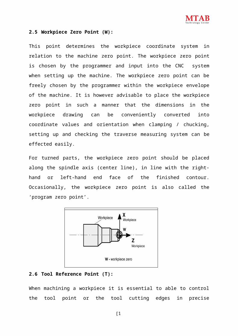
2.5 Workpiece Zero Point (W):
This point determines the workpiece coordinate system in relation to the machine zero
point. The workpiece zero point is chosen by the programmer and input into the CNC
system when setting up the machine. The workpiece zero point can be freely chosen by the
programmer within the workpiece envelope of the machine. It is however advisable to place
the workpiece zero point in such a manner that the dimensions in the workpiece drawing
can be conveniently converted into coordinate values and orientation when clamping /
chucking, setting up and checking the traverse measuring system can be effected easily.
For turned parts, the workpiece zero point should be placed along the spindle axis (center
line), in line with the right-hand or left-hand end face of the finished contour. Occasionally,
the workpiece zero point is also called the ‘program zero point’.
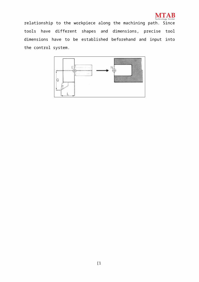
2.6 Tool Reference Point (T):
When machining a workpiece it is essential to able to control the tool point or the tool
cutting edges in precise relationship to the workpiece along the machining path. Since tools
have different shapes and dimensions, precise tool dimensions have to be established
beforehand and input into the control system.

3P6P5
2
P4P3
1P2
P1(0, 0)
302010
[13]
The tool dimensions are related to a fixed tool setting point during pre-setting. The tool
setting point E is located at a certain point on the tool holder. This setting point permits
measuring of tools away from the CNC machine. The data thus measured such as tool
length, tool point offset or tool radius are input into the tool data storage (memory) of the
control system. The mate of the tool settings point is the socket point N on the tool carrier.
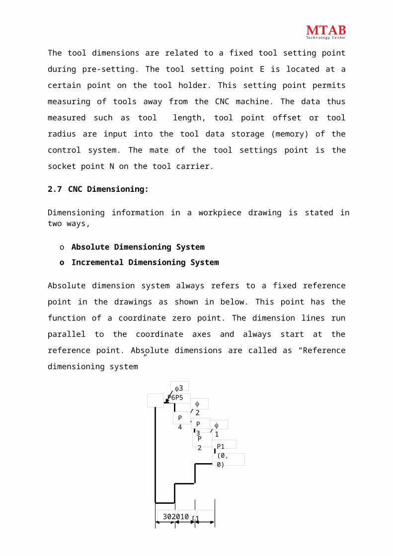
2.7 CNC Dimensioning:
Dimensioning information in a workpiece drawing is stated in two ways,
o Absolute Dimensioning System
o Incremental Dimensioning System
Absolute dimension system always refers to a fixed reference point in the drawings as
shown in below. This point has the function of a coordinate zero point. The dimension lines
run parallel to the coordinate axes and always start at the reference point. Absolute
dimensions are called as “Reference dimensioning system”
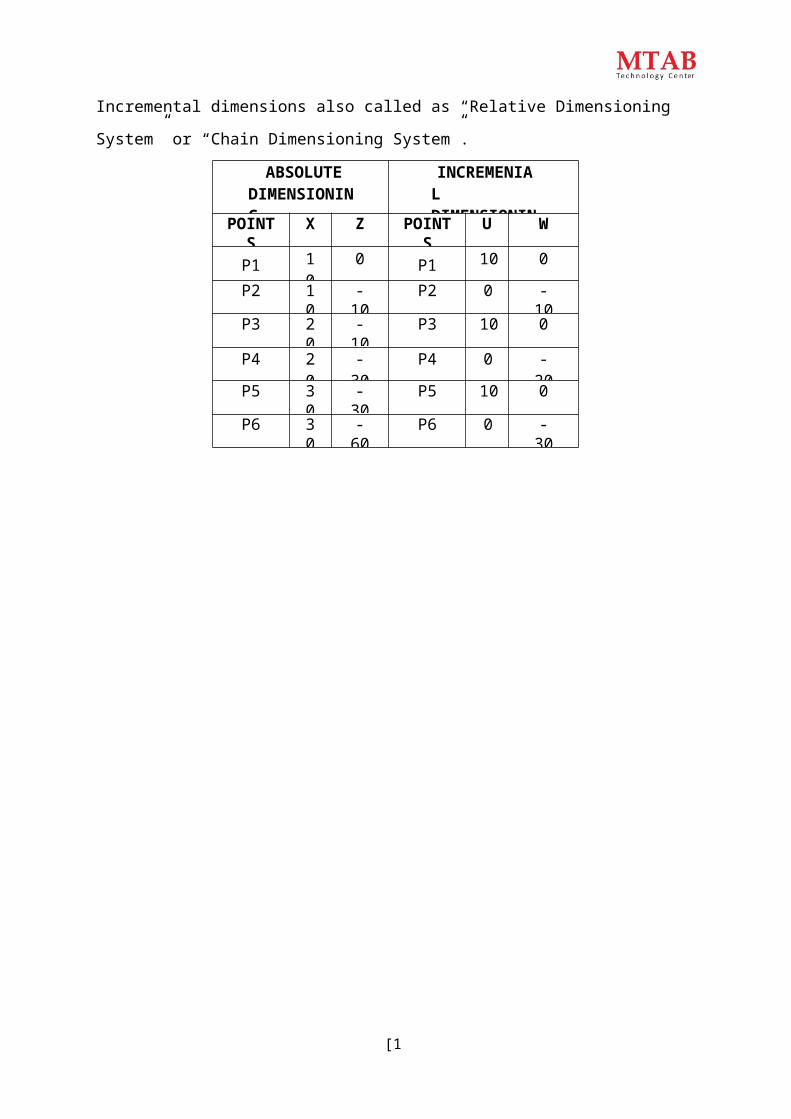
When using incremental dimension system every measurement refers to a previously
dimensioned position. Incremental dimensions are distance between adjacent points. These
distances are converted into incremental coordinates by accepting the last dimension point
as the coordinate origin for the new point. This may be compared to a small coordinate
system, i.e., shifted consequently from point to point (P1… P2… through P6) as shown.

[14]
Incremental dimensions also called as “Relative Dimensioning System” or “Chain
Dimensioning System”.
ABSOLUTE DIMENSIONING
INCREMENIAL DIMENSIONING
POINTS X Z POINTS U W
P1 10 0 P1 10 0
P2 10 -10 P2 0 -10
P3 20 -10 P3 10 0
P4 20 -30 P4 0 -20
P5 30 -30 P5 10 0
P6 30 -60 P6 0 -30

[15]
3. CNC PROGRAM BULID UP:
In a CNC program, the machining steps (operations) for producing a part on the machine
tool are laid down in a form that the control system can understand. A program is composed
of several blocks. A block is a collection of CNC word which address letter and a sequence of
number, refer the given below table.
Address Characters As Per DIN 66025Character Meaning
A Rotation about, X- axisB Rotation about, Y- axisC Rotation about, Z axis
D&E Rotation about additional axesF FeedG Preparatory function, identifying the action to be
executedH UnassignedI Interpolation Parameter / Thread pitch parallel to X-axisJ Interpolation Parameter / Thread pitch parallel to Y-axisK Interpolation Parameter / Thread pitch parallel to Z-axisM Machine function / Auxiliary functionN Block numberO Program Number
P,Q,R Parameters are used in cyclesS Spindle speedT Tool Function
U,V,W Second movement parallel to X, Y, Z axes respectivelyX Movement in X-axisY Movement in Y-axisZ Movement in Z -axis
:

[16]
3.2 Miscellaneous Function (M Codes)
When a 3-digit figure the M-code address is specified, a 3-digit BCD code signal and a strobe
signal are transmitted. This signal is used for ON / OFF control of the machine function such
as tool change, spindle rotation, coolant ON and OFF etc. M code can be specified in one
block for the function of varies machine tool builder

[17]
Miscellaneous Function (M Codes)M Codes Description
M00 Program StopM01 Optional StopM02 Program EndM03 Spindle Rotation ClockwiseM04 Spindle Rotation Counter ClockwiseM05 Spindle StopM06 Tool ChangeM08 Coolant OnM09 Coolant OffM10 Chuck OpenM11 Chuck CloseM30 Program Stop and RewindM62 Output 1 OnM63 Output 2 OnM64 Output 1 OffM65 Output 2 OffM66 Wait input 1 OnM67 Wait input 2 OnM76 Wait input 1 OffM77 Wait input 2 OffM98 Sub-program CallM99 Sub-program Exit
3.3 Preparatory Functions (G Codes):
A 2-digit number following the address G determines the meaning of command used in the
block. G codes are divided into two types,
i) One shot G code: The G code is effective only in the block in which it is specified.
ii) Modal G code: The G code is effective until another G code of the same group is
specified.
Notes:
G codes marked with * are initial G codes when turning program ON, for G20 and
G21, the G code before turning power off remains.
G codes of group 00 are not modal. They are only effective in the block in which they
are specified.
[18]
G CODE Group FunctionG00* 01 Positioning (Rapid traverse)
G0l Linear interpolation (Cutting feed)G02 Circular interpolation (Clockwise)G03 Circular interpolation ( Counter Clockwise)G04 00 Dwell
G17* 02 XY plane selectionG18 ZX plane selectionG19 YZ plane selectionG20 06 Input in inch
G21 Input in mmG28 00 Return to reference point
G40* 07 Tool Nose Radius compensation cancelG41 Tool Nose Radius compensation leftG42 Tool Nose Radius compensation rightG70 04 Finishing CycleG71 Multiple Turning CycleG72
00
Multiple Facing CycleG73 Pattern Repeating CycleG74 Drilling CycleG75 Grooving Cycle
G76 Multiple Threading CycleG90 01 Turning CycleG92 Threading CycleG94 Facing Cycle
G96 02 Constant Surface Speed ControlG97* Constant Surface Speed Control CancelG98 11 Feed Per MinuteG99 Feed Per Revolution
If any G code of group 01 is specified in a canned cycle mode, the canned cycle is
automatically cancelled and the G80 condition is entered. However a G code of
group 01 is not affected by any of the canned cycle G codes.
All the G codes may not apply to each machine.
[19]
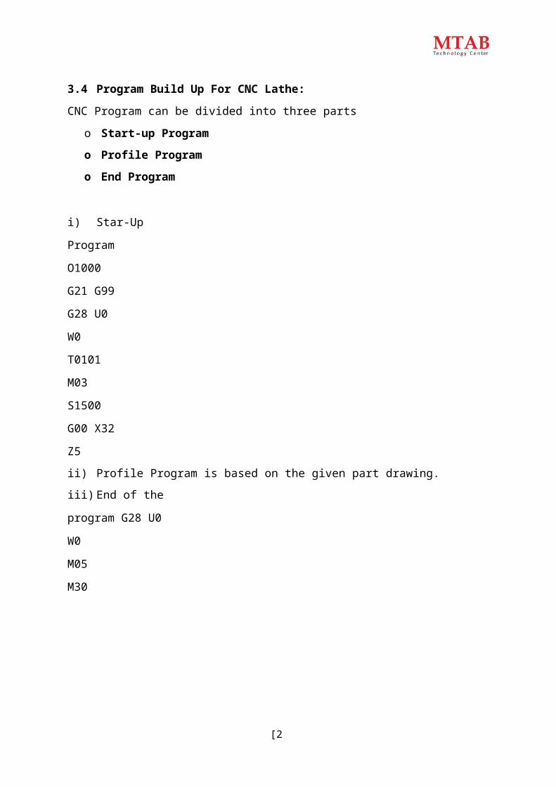
3.4 Program Build Up For CNC Lathe:
CNC Program can be divided into three parts
o Start-up Program
o Profile Program
o End Program
i) Star-Up
Program O1000
G21 G99
G28 U0 W0
T0101
M03 S1500
G00 X32 Z5
ii) Profile Program is based on the given part drawing.
iii) End of the
program G28 U0 W0
M05
M30
[20]
4. PROGRAMMING EXAMPLES:
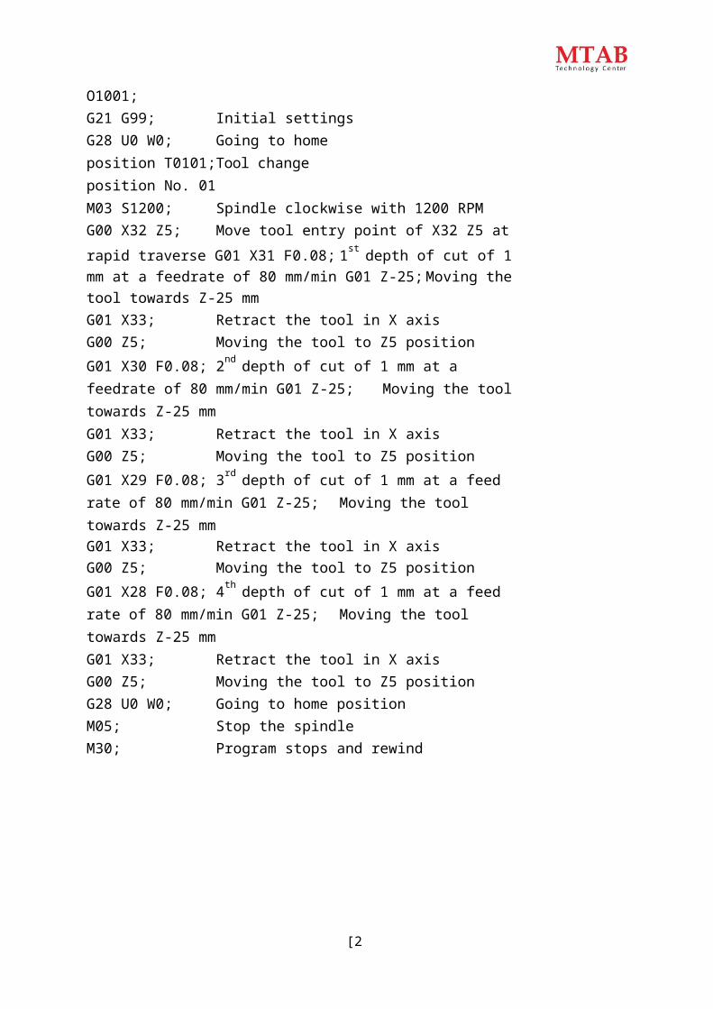
4.1 Programming for turning operation using linear command:
[21]
O1001;G21 G99; Initial settingsG28 U0 W0; Going to home position T0101; Tool change position No. 01M03 S1200; Spindle clockwise with 1200 RPMG00 X32 Z5; Move tool entry point of X32 Z5 at rapid traverse G01 X31 F0.08; 1st depth of cut of 1 mm at a feedrate of 80 mm/min G01 Z-25; Moving the tool towards Z-25 mmG01 X33; Retract the tool in X axisG00 Z5; Moving the tool to Z5 positionG01 X30 F0.08; 2nd depth of cut of 1 mm at a feedrate of 80 mm/min G01 Z-25; Moving the tool towards Z-25 mmG01 X33; Retract the tool in X axisG00 Z5; Moving the tool to Z5 positionG01 X29 F0.08; 3rd depth of cut of 1 mm at a feed rate of 80 mm/min G01 Z-25; Moving the tool towards Z-25 mmG01 X33; Retract the tool in X axisG00 Z5; Moving the tool to Z5 positionG01 X28 F0.08; 4th depth of cut of 1 mm at a feed rate of 80 mm/min G01 Z-25; Moving the tool towards Z-25 mmG01 X33; Retract the tool in X axisG00 Z5; Moving the tool to Z5 positionG28 U0 W0; Going to home positionM05; Stop the spindleM30; Program stops and rewind
[22]

[23]
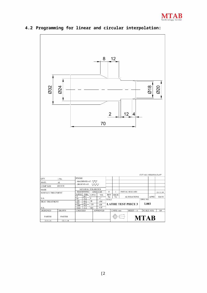
4.2 Programming for linear and circular interpolation:
[24]
NOTE: This Program is for Simulation only (not for Machining Practice) O1003;G21 G99; Initial settingsG28 U0 W0; Going to home position T0101; Tool change position No. 01M03 S1200; Spindle clockwise with 1200 RPMG00 X32 Z5; Move tool entry point of X32 Z5 at rapid traverse G01 X18 F0.08; First point in X axis at a feed rate of 80 mm/min G01 Z0; Defining Z axisG01 X20 Z-4 F0.08; Moving the tool both X and Z axes G01 Z-16; Moving the tool to Z-16 mm positionG03 X24 Z-18 R4; Tool movement in circular interpolation with CCW G01 Z-30; Tool Movement along Z-30 mmG01 X32 Z-38; Tool movement both X and Z axes G28 U0 W0; Going to home positionM05; Stop the spindleM30; Program Stop & Rewind

[25]
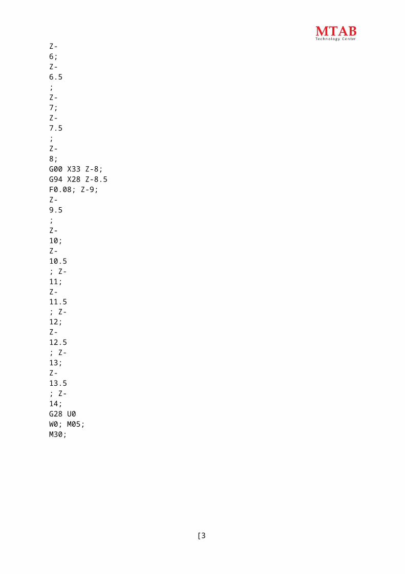
4.3 Programming for facing cycle (G94):

[30]
Facing Cycle (G94): This cycle is used for stock removal in parallel tool path. It is equivalent of
Rapid to Z position Feed to X position Feed to start Z position Rapid to start X position
Format:
X – Diameter to which the movement is being made.Z – Z-axis coordinate to which the movement is being made. F – Feed Rate.O1004;G21 G99; Initial settingsG28 U0 W0; Going to home positionT0101; Tool change position No. 01M03 S1200; Spindle clockwise with 1200 RPMG00 X33 Z5; Move tool entry point of X33 Z5 at rapid traverse G94 X22 Z-0.5 F0.08; Calling G94 Cycle and defining first depth of cut Z-1; Defining Second Depth of cutZ-1.5; Z-2;Z-2.5; Z-3;Z-3.5; Z-4;Z-4.5; Z-5;Z-5.5; Z-6;Z-6.5; Z-7;Z-7.5; Z-8;G00 X33 Z-8;G94 X28 Z-8.5 F0.08; Z-9;Z-9.5; Z-10;Z-10.5; Z-11;Z-11.5; Z-12;Z-12.5; Z-13;Z-13.5; Z-14;G28 U0 W0; M05;M30;
G94 X Z F;

[27]
4.4 Programming for Turning Cycle (G90):
[28]
Turning Cycle (G90): This cycle is used for stock removal in parallel tool path. This cycle performs four distinct moves with one line of information. It is equivalent of
Rapid to X position. Feed to Z position. Feed to start X position. Rapid to start Z position.
Format:
X – Diameter to which the movement is being made.Z – Z-axis coordinate to which the movement is being made. F – Feed Rate.
O1006;G21 G99; Initial settingsG28 U0 W0; Going to home position T0101; Tool change position No. 01M03 S1200; Spindle clockwise with 1200 RPMG00 X33 Z5; Move tool entry point of X33 Z5 at rapid traverse G90 X31 Z-26 F0.01; Calling G90 Cycle and defining first depth of cut X30; Defining second depth of cutX29; X28;G90 X27 Z-14 F0.01; X26;X25; X24; X23; X22;G28 U0 W0; M05;M30;
G90 X Z F;

[29]
4.5 Programming for multiple turning cycle (G71):
G71G71
U (Δd)R (e);P (A')Q (B) U (Δu) W(Δw)F;
[30]
Multiple Turning Cycle (G71): Multiple turning cycles is used when the major direction of cut is along the ‘Z’ axis. This cycle requires two blocks are needed to specify all the parameters.
Format:
W – Depth of cut in X axis. R – Relief amount.P – Starting block of the profile. Q – Finishing block of the profile. U – Finishing allowance in X axis. W – Finishing allowance in Z axis. F – Feed Rate.
O1007;G21 G99; Initial settingsG28 U0 W0; Going to home position T0101; Tool change position No. 01M03 S1200; Spindle clockwise with 1200 RPMG00 X32 Z5; Move tool entry point X32 Z5 at rapid traverseG71 U0.5 R1; Calling G71 Cycle and defining Cycle Parameters G71 P1 Q2 U0.1 W0.1 F0.01; Defining Cycle ParametersN1 G01 X18; G01 Z0;G01 X20 Z-4; G01 Z-16;G03 X24 Z-18 R4; G01 Z-30;N2 G01 X32 Z-38; G28 U0 W0;M06 T2; M03 S1500; G00 X32 Z5;G70 P1 Q2 S1500 F0.08; G28 U0 W0;M05; M30;

[31]
4.6 Programming for grooving Cycle (G75):
[40]
G75G75
R (e);X Z PQ F;
Grooving Cycle (G75): This cycle is designated for grooving. This cycle also requires two blocks are needed to specify all the parameters.
Format:
R – Return amount, mm.X – Total depth along X axis, mm. Z – Total width along Z axis, mm.P – Depth of cut in X axis (in Micron, in mm).Q – Stepping distance in Z axis (in Micron, in mm). F – Feed Rate, rev/min.
O1009;G21 G99; Initial SettingsG28 U0 W0; Going to home position T0101; Tool Change Position No. 01M03 S500; Spindle clockwise with 500 RPMG00 X33 Z-18; Move tool entry point X33 Z-18 at rapid TraversG75 R1; Calling G75 Cycle and defining Cycle Parameters G75 X28 Z-20 P0.05 Q0.1 F0.04; Defining Cycle ParametersG28 U0 W0; M05;M30;

[41]
4.7 Programming for multiple threading cycle (G76):

M30
G76G71
P (m) (r) (a)Q (Δd min)R (d);X Z P (k) Q (Δd) F;
Minor Diameter Calculationd= Minor Diameter D= Minor Diameter P= Thread Height d= D – 2 (P)d= 32 – 2 (0.613)d= 32 – 1.226d= 30.774Thread Height, P = 0.613 x Pitch of the Thread= 0.613 x 1P = 0.613
[42]
Multiple Threading Cycles (G76): Thread cutting cycle can be commanded by the G76 command as shown in the figure. This cycle also requires two blocks are needed to specify all the parameters. Format:
m – No. of repeats for finishing operation. r – Chamfering amount.a – Tool angle, degree.Q – Minimum cutting depth, (in Micron, in mm). R – Finishing allowance, (in mm).X – Minor Diameter, m.Z – Thread length, mm.P (k) – Thread height, (in Micron, in mm).Q (Δd) – Depth of cut for first pass (in Micron, in mm). F – Pitch of the thread, mm.
O1010;G21 G99; Initial settingsG28 U0 W0; Going to home position T0101; Tool change position No. 01M03 S500; Spindle clockwise with 500 RPMG00 X32.5 Z5; Move to tool entry X32.5 Z5 at rapid traverse G76 P030060 Q0.05 R0.02; Calling G76 Cycle and defining cycle parameters G76 X30.774 Z-14 P0.613 Q0.1 F1;G28 U0 W0; M05;M30;

[43]
4.8 Programming for drilling cycle (G74):
[44]
Drilling Cycle (G74): This cycle is designed for deep hole drilling, the drill entering the workpiece by a predetermined amount then backing off by another set amount to provide breaking and allowing swarf to clear the drill flutes. This cycle is commanded by two distinct lines of parameters. Format:
G74 R (e);G74 X Z Q(Δk) F;
R (e) – Return amount, mm. X – Always zero, mm.Z – Drilling depth, mm.Q – Depth of cut in Z axis (in Micron). F – Feed Rate,mm.
O1011;G21 G99; - Initial settingsG28 U0 W0; - Going to home positionT0101; - Tool change position no. 01M03 S500; - Spindle clockwise with 500 rpmG00 X0 Z5; - Moving to tool entry point of X0 Z5 at rapid traverse G74 R1; - Calling G74 cycle and defining parametersG74 X0 Z-5 Q0.5 F0.1; G28 U0 W0;T0202; - Tool change position no. 02 M03 S500;G00 X0 Z5;G74 R1; - Calling G74 cycle and defining parameters G74 X0 Z-24 Q0.5 F0.08;G28 U0 W0;T0303; - Tool change position no. 03 M03 S500;G00 X0 Z5;G74 R1; - Calling G74 cycle and defining parameters G74 X0 Z-24 Q0.5 F0.06;G28 U0 W0; M05;M30;

[45]
4.9 Programming for boring operation:

[46]
O1012;G21 G99; - Initial settingsG28 U0 W0; - Going to home positionT0101; - Tool change position no. 01M03 S500; - Spindle clockwise with 500 rpmG00 X0 Z5; - Moving to tool entry point of X0 Z5 at rapid traverse G74 R1; - Calling G74 cycle and defining parametersG74 X0 Z-5 Q0.5 F0.1; G28 U0 W0;T0202; - Tool change position no. 02 M03 S1000;G00 X0 Z5;G74 R1; - Calling G74 cycle and defining parameters G74 X0 Z-24 Q0.5 F0.08;G28 U0 W0;T0303; - Tool change position no.03 M03 S1000;G00 X0 Z5;G74 R1; - Calling G74 cycle and defining parameters G74 X0 Z-24 Q0.5 F0.06;G28 U0 W0;T0404; - Tool change position no. 04 M03 S1000;G00 X12 Z5;G71 U0.5 R1; - Calling G71 cycle and defining parameters G71 P1 Q2 U-0.1 W0.1 F0.08; -“U” inner finishing allowanceN1 G01 X26; G01 Z0;G02 X22 Z-2 R4; G01 Z-14;G01 X16 Z-20; N2 G01 X12;G70 P1 Q2 S1200 F0.06; G28 U0 W0;M05; M30;

[47]
4.10 Programming for internal threading operation:

[48]
O1013;G21 G99; Initial SettingsG28 U0 W0; Going to home positionT0101; Tool change position no. 01M03 S1200; Spindle clockwise with S1200 rpmG00 X0 Z5; Moving to tool entry point of X0 Z5 at rapid traverse G74 R1; Calling G74 Cycle and defining parametersG74 Z-5 Q0.5 F0.1; G28 U0 W0;T0202; Tool change position no. 02 M03 S1200;G00 X0 Z5;G74 R1; Calling G74 cycle and defining parameters G74 Z-30 Q0.5 F0.08;G28 U0 W0;T0303; Tool change position no. 03 M03 S1200;G00 X0 Z5;G74 R1; Calling G74 cycle and defining parameters G74 Z-30 Q0.5 F0.06;G28 U0 W0;T0404; Tool change position no. 04 M03 S1200;G00 X12 Z5;G90 X13 Z-24 F0.08; Calling G90 cycle and defining parameters X14;X15; X16;X17 Z-18; X18; X19; X20; X21; X22; X23; X24; X24.162;G28 U0 W0; T0505;M03 S500;G76 P030060 Q0.05 R0.03;G76 X26 Z-14 P0.919 Q0.1 F1.5; G28 U0 W0;M05; M30;

[49]

[51]

[52]

MTAB Technology Center PVT LTD#133, Developed Plot, Electrical & Electronics Industrial Estate Perungudi, Chennai - 600096.
Tamilnadu, INDIA. Tel: +91-44-43111114E-mail : [email protected] Visit us at : www.mtabtraining.com
MTC reserves the rights to alter any parts of this publications without prior notice.