Embed Size (px)
Citation preview
Additives & InstrumentsA member of
Measure what you see.
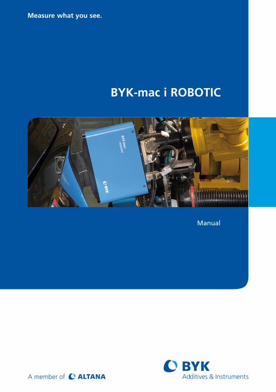
BYK-mac i ROBOTIC
Manual
1
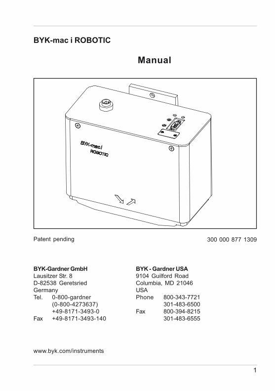
BYK-mac i ROBOTIC
Manual
Patent pending 300 000 877 1309
BYK-Gardner GmbHLausitzer Str. 8D-82538 GeretsriedGermanyTel. 0-800-gardner
(0-800-4273637)+49-8171-3493-0
Fax +49-8171-3493-140
BYK - Gardner USA9104 Guilford RoadColumbia, MD 21046USAPhone 800-343-7721
301-483-6500Fax 800-394-8215
301-483-6555
www.byk.com/instruments

2
Dear customer,thank you for having decided for a BYK-Gardnerproduct. BYK-Gardner is committed to providing youwith quality products and services. We offercomplete system solutions to solve your problemsin areas of color, appearance and physicalproperties. As the basis of our worldwide business,we strongly believe in total customer satisfaction.Therefore, in addition to our products, we offer manyVALUE-ADDED services:· Technical Sales Force· Technical & Application Support· Application and Technical Seminars· Repair & Certification Service
BYK-Gardner is part of Altana AG and a directsubsidiary of BYK-Chemie GmbH, a leading supplierof additives for coatings and plastics. Together, weoffer complete and unique solutions for you, ourcustomer.
Thank you for your trust and confidence. If there isanything we can do better to serve your needs, donot hesitate to let us know.
Your BYK-Gardner Team
3
Table of content
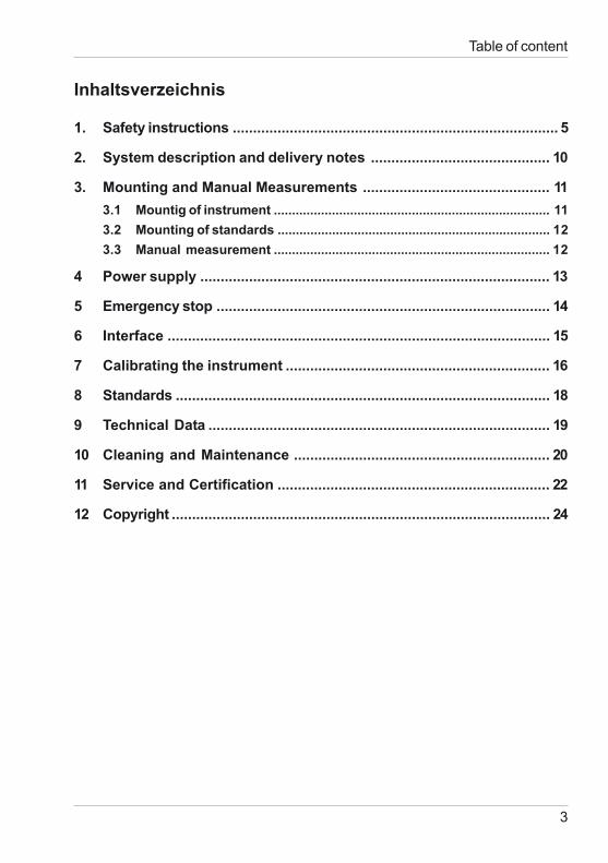
Inhaltsverzeichnis
1. Safety instructions ................................................................................ 5
2. System description and delivery notes ............................................ 10
3. Mounting and Manual Measurements .............................................. 113.1 Mountig of instrument ............................................................................ 113.2 Mounting of standards ........................................................................... 123.3 Manual measurement ............................................................................ 12
4 Power supply ...................................................................................... 13
5 Emergency stop .................................................................................. 14
6 Interface .............................................................................................. 15
7 Calibrating the instrument ................................................................. 16
8 Standards ............................................................................................ 18
9 Technical Data .................................................................................... 19
10 Cleaning and Maintenance ............................................................... 20
11 Service and Certification ................................................................... 22
12 Copyright ............................................................................................. 24

4
5
Safety instructions
1. Safety instructions • Before operating the instrument the first time,
please read the operating instructions and takeparticular notice of the safety instructions.
• If you use the unit and accessories properly,there are no hazards to fear.
• This product is equipped with safety features.Nevertheless, read the safety warnings carefullyand use the product only as described in theseinstructions to avoid accidental injury or damage.
• No claims of product liability or warranty can behonored if the device is not operated inaccordance with the operating instructions.
• Keep these instructions for future reference.
• If you pass this instrument to somebody else,make sure to include these instructions.
6
Safety instructions
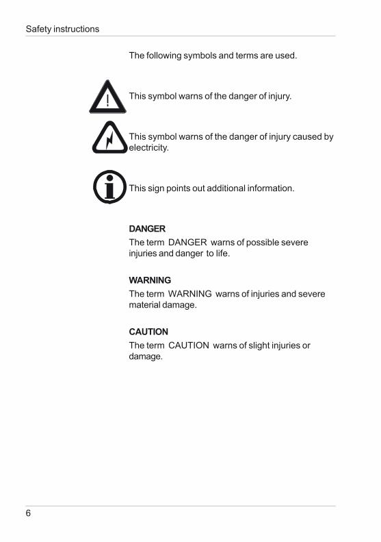
The following symbols and terms are used.
This symbol warns of the danger of injury.
This symbol warns of the danger of injury caused byelectricity.
This sign points out additional information.
DANGERThe term DANGER warns of possible severeinjuries and danger to life.
WARNINGThe term WARNING warns of injuries and severematerial damage.
CAUTIONThe term CAUTION warns of slight injuries ordamage.
7
DANGER injuries possible
• Defects and extraordinary loadsIf safe operation can no longer be presumed,shut down the device and secure it againstunintended operation.
The device must be presumed unsafe to operate:• if visible damage is evident• if the instrument is no longer working• if it has been stored for long periods under
adverse conditions• after harsh treatment during shipping.• For operation with the external power supply, care
should be taken to ensure the nominal voltage of thepower supply unit (see the manufacturer’s plate onthe power supply unit) matches the voltage suppliedby the power outlet.
• Do not perform any repairs on the unit yourself.The unit must be opened by trained professionalsonly. Please contact our customer servicedepartment in such cases.
• The measurement device and accessories maybe disconnected from the power supply asfollows:Instrument:by disconnecting the plug from the device.
Safety instructions
8
Safety instructions
WARNING severe material damage
• The measurement unit consists of sensitiveoptical and electronic precision parts. Prevent itfrom being dropped, bumped or shaken!
• Avoid exposure to continuous humidity andcondensation. Avoid splashing with water,chemicals or other liquids.
• Please use only accessories that are availablefor the unit.
• Only devices that meet the requirements for low-voltage safety may be connected to the RS 422interface.
CAUTION material damage
• Do not allow any foreign objects to get into themeasurement opening.
• Do not expose the unit to direct sunlight forextended periods of time. Do not store it in a hotor dusty environment. Use the instrument casefor storage.
9
• Avoid prolonged high relative humidity and do notallow condensation water.
• Do not use any acetone for cleaning theunit! The unit housing is resistant to manysolvents. For cleaning you should use a soft,moist cloth. Excessive dirt and dust can beremoved with ethanol or cleaning alcohol.
Additonal information on use:
• You will find the technical data for all systemcomponents such as the measurement unit andbattery compartment on the respectivemanufacturer’s plates and in the sectionTechnical Data
• This symbol means: Do not dispose of thisproduct together with your household waste.Please refer to the information of your localcommunity or contact our dealers regarding theproper handling of end-of life electric andelectronic equipment.Recycling of this product will help to conservenatural resources and prevent potential negativeconsequences for the environment and humanhealth caused by inappropriate waste handling.
Safety instructions
10
2. System description and Delivery notesBYK-mac i ROBOTIC measures color traditionallyat five aspecular angles (15°/25°/45°/75°/110°) with a45° illumination. Additional color measurement”behind” the gloss for color travel of interferencepigments is implemented at -15°. To simulatesparkle under direct sunlight additional illuminationsare used at 15° /45° and 75°. Diffused illuminationfor graininess evaluation is created by two whitecoated hemispheres. Detection is performed by ahigh resolution camera situated perpendicular to thesurface. Additional out-of-plane sensors detectfluorescent light excited in the visible range andquantify it by the Intensity Emission value.The instrument complies with the followingstandards: DIN 5033, 5036, 6174, 6175-2; DIN ENISO 11664, ISO 7724; ASTM D2244, E308, E2194,E 1164, SAE J1545.
BYK - mac i ROBOTIC 7036
Comes complete with:
Multi-angle spectrophotometer, white calibrationstandard with certificate, cyan and effect checkingreference, light protection cover, BYKWAREsmart-process software, communication software,installation kit, operating manual on CD, carryingcase, training.
Accessories and spare partsLight Protection Cover 6417BYKWARE smart-process 4831BYKWARE smart-lab 4862Manual Measurement Adapter 281 021 621
System description and Delivery notes
11
Mounting and Manual Measurements
3. Mounting and Manual MeasurementsBefore operating the instrument for the first time,please read the operating manual and takeparticular notice of the Safety Instructions.
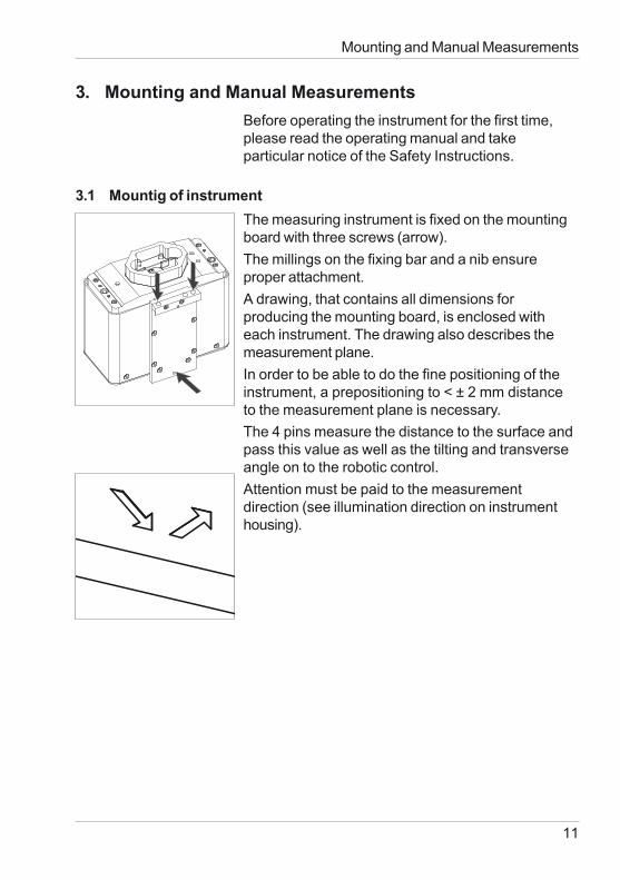
3.1 Mountig of instrumentThe measuring instrument is fixed on the mountingboard with three screws (arrow).The millings on the fixing bar and a nib ensureproper attachment.A drawing, that contains all dimensions forproducing the mounting board, is enclosed witheach instrument. The drawing also describes themeasurement plane.In order to be able to do the fine positioning of theinstrument, a prepositioning to < ± 2 mm distanceto the measurement plane is necessary.The 4 pins measure the distance to the surface andpass this value as well as the tilting and transverseangle on to the robotic control.Attention must be paid to the measurementdirection (see illumination direction on instrumenthousing).
12
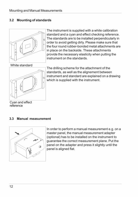
3.2 Mounting of standards
The instrument is supplied with a white calibrationstandard and a cyan and effect checking reference.The standards are to be installed perpendicularly inorder to avoid getting dirty. Please make sure thatthe four round rubber-bonded metal attachments arein place on the backside. These attachmentsprovide the necessary elasticity when putting theinstrument on the standards.
The drilling scheme for the attachment of thestandards, as well as the alignement betweeninstrument and standard are explained on a drawingwhich is supplied with the instrument.
3.3 Manual measurement
In order to perform a manual measurement e.g. on amaster panel, the manual measurement adapter(optional) has to be installed on the instrument toguarantee the correct measurement plane. Put thepanel on the adapter and press it slightly until thepanel is aligned flat.
Mounting and Manual Measurements
White standard
Cyan and effectreference
13
Power supply
4 Power supply
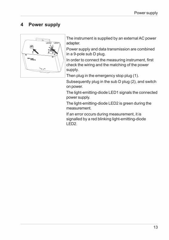
The instrument is supplied by an external AC poweradapter.Power supply and data transmission are combinedin a 9-pole sub D plug.In order to connect the measuring instrument, firstcheck the wiring and the matching of the powersupply.Then plug in the emergency stop plug (1).Subsequently plug in the sub D plug (2), and switchon power.The light-emitting-diode LED1 signals the connectedpower supply.The light-emitting-diode LED2 is green during themeasurement.If an error occurs during measurement, it issignalled by a red blinking light-emitting-diodeLED2.
LED2 LED1
12
14
5 Emergency stop
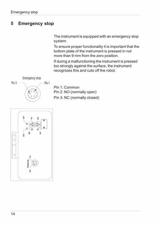
The instrument is equipped with an emergency stopsystem.To ensure proper functionality it is important that thebottom plate of the instrument is pressed in notmore than 9 mm from the zero position.If during a malfunctioning the instrument is pressedtoo strongly against the surface, the instrumentrecognizes this and cuts off the robot.
Pin 1: CommonPin 2: NO (normally open)Pin 3: NC (normally closed)
Emergency stop
E
merg
ency
stop
Pin 1
Pin 5
Pin 9
Pin 6
Pin 1
Pin 3
LED
1LE
D 2
Emergency stopPin 1Pin 3
15
Interface
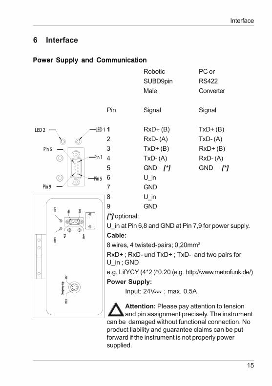
6 Interface
Power Supply and CommunicationPower Supply and CommunicationPower Supply and CommunicationPower Supply and CommunicationPower Supply and Communication
Robotic PC orSUBD9pin RS422Male Converter
Pin Signal Signal
1 RxD+ (B) TxD+ (B)2 RxD- (A) TxD- (A)3 TxD+ (B) RxD+ (B)4 TxD- (A) RxD- (A)5 GND [*] GND [*]6 U_in7 GND8 U_in9 GND[*] optional:U_in at Pin 6,8 and GND at Pin 7,9 for power supply.Cable:8 wires, 4 twisted-pairs; 0,20mm²RxD+ ; RxD- und TxD+ ; TxD- and two pairs forU_in ; GNDe.g. LifYCY (4*2 )*0.20 (e.g. http://www.metrofunk.de/)Power Supply:
Input: 24V ; max. 0.5A
E
merg
ency
stop
Pin 1
Pin 5
Pin 9
Pin 6
Pin 1
Pin 3
LED
1LE
D 2
Attention: Please pay attention to tensionand pin assignment precisely. The instrument
can be damaged without functional connection. Noproduct liability and guarantee claims can be putforward if the instrument is not properly powersupplied.
Pin 1
Pin 5Pin 9
Pin 6
LED 1LED 2
16
7 Calibrating the instrument
7.1 Calibration Information
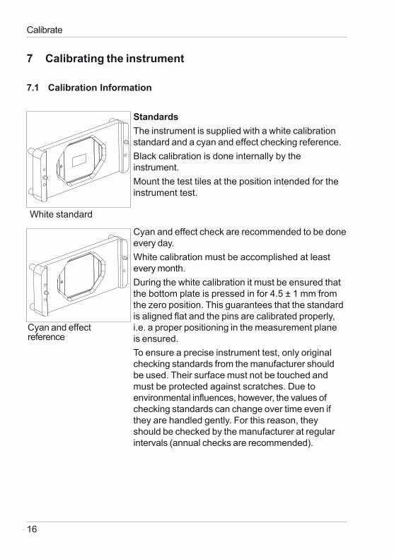
StandardsThe instrument is supplied with a white calibrationstandard and a cyan and effect checking reference.Black calibration is done internally by theinstrument.Mount the test tiles at the position intended for theinstrument test.
Cyan and effect check are recommended to be doneevery day.White calibration must be accomplished at leastevery month.During the white calibration it must be ensured thatthe bottom plate is pressed in for 4.5 ± 1 mm fromthe zero position. This guarantees that the standardis aligned flat and the pins are calibrated properly,i.e. a proper positioning in the measurement planeis ensured.To ensure a precise instrument test, only originalchecking standards from the manufacturer shouldbe used. Their surface must not be touched andmust be protected against scratches. Due toenvironmental influences, however, the values ofchecking standards can change over time even ifthey are handled gently. For this reason, theyshould be checked by the manufacturer at regularintervals (annual checks are recommended).
Calibrate
White standard
Cyan and effectreference
17
Calibrate
7.2 Calibration Notes
• The standards should be cleaned periodically.For cleaning procedure see section "Cleaningand Maintenance“. Please make sure that thestandards are not scratched.
• Do not move the instrument while taking acalibration measurement. If motion is detected,an error message will be displayed andcalibration is aborted.
• When moving from cold to warm environment,there is a danger of condensation. For thisreason, you should wait for an appropriateamount of time to allow the optical componentsto adjust before calibrating and using the unit.
18
8 Standards
DIN 5033 Colorimetry; basic concepts.
DIN 5036 Radiometric and photometric properties of materials;definitions characteristic.
DIN 6174 Colorimetric evaluation of colour differences ofsurface colours according to the CIELAB formula.
DIN 6175-2 Tolerances for automotive paintsPart 2: Goniochromatic paints
DIN EN ISO 11664 Colorimetry
ISO 7724 Paints and varnishes - Colorimetry
ASTM D 2244 Standard Test Method for Calculation of ColorDifferences From Instrumentally MeasuredColor Coordinates.
ASTM E 308 Standard Practice for Computing the Colors ofObjects by Using the CIE System.
ASTM E 1164 Standard Practice for Obtaining SpectrophotometricData for Object-Color Evaluation.
ASTM E 2194 Standard Practice for Multiangle Color Measurementof Metal Flake Pigmented Materials
SAE J 1545 Instrumental Color Difference Measurement forExterior Finishes, Textiles and Colored Trim
Standards
19
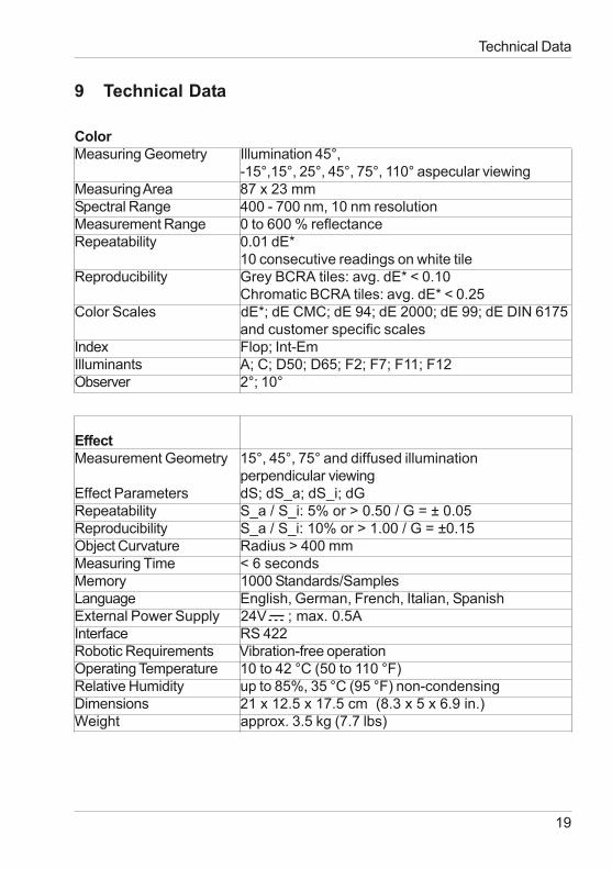
9 Technical Data
ColorMeasuring Geometry Illumination 45°,
-15°,15°, 25°, 45°, 75°, 110° aspecular viewingMeasuring Area 87 x 23 mmSpectral Range 400 - 700 nm, 10 nm resolutionMeasurement Range 0 to 600 % reflectanceRepeatability 0.01 dE*
10 consecutive readings on white tileReproducibility Grey BCRA tiles: avg. dE* < 0.10
Chromatic BCRA tiles: avg. dE* < 0.25Color Scales dE*; dE CMC; dE 94; dE 2000; dE 99; dE DIN 6175
and customer specific scalesIndex Flop; Int-EmIlluminants A; C; D50; D65; F2; F7; F11; F12Observer 2°; 10°
EffectMeasurement Geometry 15°, 45°, 75° and diffused illumination
perpendicular viewingEffect Parameters dS; dS_a; dS_i; dGRepeatability S_a / S_i: 5% or > 0.50 / G = ± 0.05Reproducibility S_a / S_i: 10% or > 1.00 / G = ±0.15Object Curvature Radius > 400 mmMeasuring Time < 6 secondsMemory 1000 Standards/SamplesLanguage English, German, French, Italian, SpanishExternal Power Supply 24V ; max. 0.5AInterface RS 422Robotic Requirements Vibration-free operationOperating Temperature 10 to 42 °C (50 to 110 °F)Relative Humidity up to 85%, 35 °C (95 °F) non-condensingDimensions 21 x 12.5 x 17.5 cm (8.3 x 5 x 6.9 in.)Weight approx. 3.5 kg (7.7 lbs)
Technical Data
20
Cleaning and Maintenance
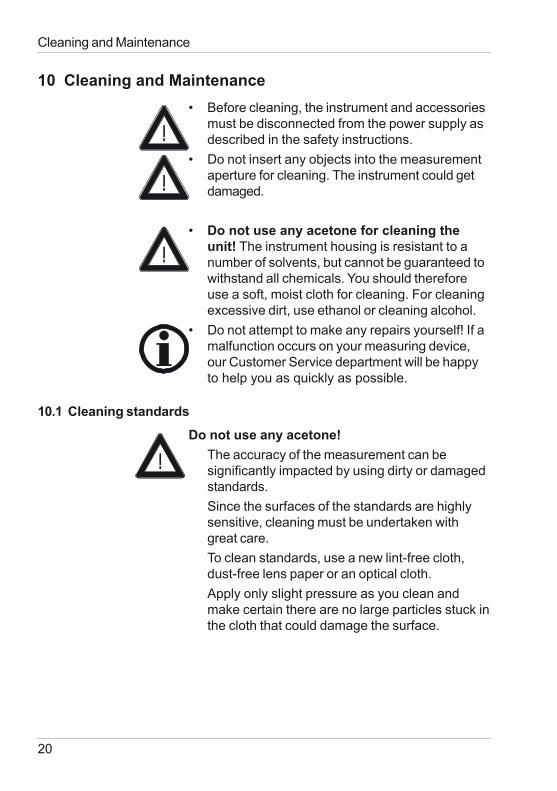
10 Cleaning and Maintenance• Before cleaning, the instrument and accessories
must be disconnected from the power supply asdescribed in the safety instructions.
• Do not insert any objects into the measurementaperture for cleaning. The instrument could getdamaged.
• Do not use any acetone for cleaning theunit! The instrument housing is resistant to anumber of solvents, but cannot be guaranteed towithstand all chemicals. You should thereforeuse a soft, moist cloth for cleaning. For cleaningexcessive dirt, use ethanol or cleaning alcohol.
• Do not attempt to make any repairs yourself! If amalfunction occurs on your measuring device,our Customer Service department will be happyto help you as quickly as possible.
10.1 Cleaning standards
Do not use any acetone!The accuracy of the measurement can besignificantly impacted by using dirty or damagedstandards.Since the surfaces of the standards are highlysensitive, cleaning must be undertaken withgreat care.To clean standards, use a new lint-free cloth,dust-free lens paper or an optical cloth.Apply only slight pressure as you clean andmake certain there are no large particles stuck inthe cloth that could damage the surface.
21
Cleaning and Maintenance
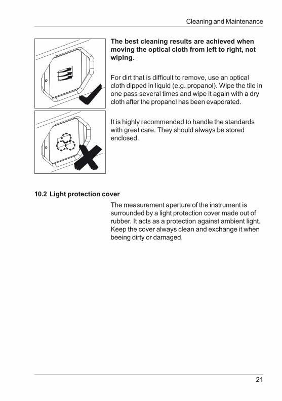
The best cleaning results are achieved whenmoving the optical cloth from left to right, notwiping.
For dirt that is difficult to remove, use an opticalcloth dipped in liquid (e.g. propanol). Wipe the tile inone pass several times and wipe it again with a drycloth after the propanol has been evaporated.
It is highly recommended to handle the standardswith great care. They should always be storedenclosed.
10.2 Light protection coverThe measurement aperture of the instrument issurrounded by a light protection cover made out ofrubber. It acts as a protection against ambient light.Keep the cover always clean and exchange it whenbeeing dirty or damaged.
22
11 Service and Certification
ServiceBesides the repair of your instrument we offer thefollowing additional services:First diagnosis on the telephone or by e-mailCall us or send us an e-mail and we will try to solveyour problem. If this is not successful, please sendus the instrument for repair.Preventive maintenance, calibration andrecertificationFor precautionary reasons we recommend regularpreventive maintenance. We carry out this preventivemaintenance automatically when you send us yourinstrument for maintenance and recertification. Weclean the optics, check all functions, test and, ifrequired, adjust the measured values by usingreference standards. You will receive a certificate,which includes the retraceability to internationalstandards.LoanersDuring the period of repair we furnish you with aloaner on request and availability.Maintenance agreementIn case you want to make sure that the necessarymaintenance is being done on a regular basis andon time, we recommend a maintenance agreement.Extended warranty contractsFurthermore, you can request an extended warrantycontract for additional 12 months.Ordering information:107207036 Preventive Maintenance BYK-mac i ROBOTIC107307036 Extended warranty BYK-mac i ROBOTIC
Service and Certification
23
Service and Certification
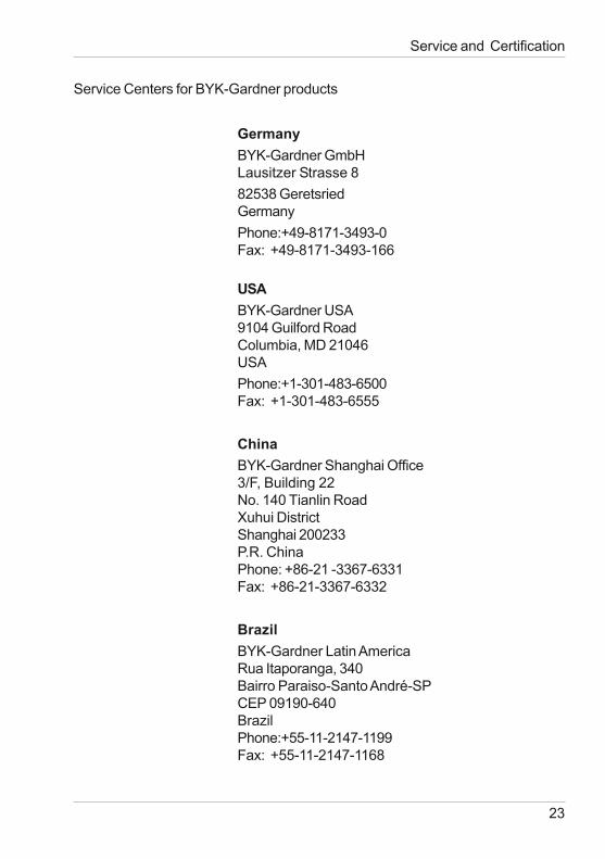
Service Centers for BYK-Gardner products
GermanyBYK-Gardner GmbHLausitzer Strasse 882538 GeretsriedGermanyPhone:+49-8171-3493-0Fax: +49-8171-3493-166
USABYK-Gardner USA9104 Guilford RoadColumbia, MD 21046USAPhone:+1-301-483-6500Fax: +1-301-483-6555
ChinaBYK-Gardner Shanghai Office3/F, Building 22No. 140 Tianlin RoadXuhui DistrictShanghai 200233P.R. ChinaPhone: +86-21 -3367-6331Fax: +86-21-3367-6332
BrazilBYK-Gardner Latin AmericaRua Itaporanga, 340Bairro Paraiso-Santo André-SPCEP 09190-640BrazilPhone:+55-11-2147-1199Fax: +55-11-2147-1168
24
12 Copyright
This instruction manual is an important part of this instrument. It contains es-sential information about setting up, placing in service and use. If you passthe device on to another user, please ensure that the instruction manual isincluded with the instrument. The manual must be studied carefully beforeworking with the equipment. Please contact your regional service office ifyou have any questions or require additional information about the device.
The technology and fittings are based on state-of-the art optic andelectronic technology. New developments and innovations are constantlybeing integrated into the equipment. Thus, the diagrams, dimensions, andtechnical data used in this manual may have changed as a result of adaptingthe device to new information and improvements.
© Copyright 2013 BYK-Gardner GmbHAll rights reserved
No portion of the software, documentation or other accompanying materialsmay be translated, modified, reproduced, copied or otherwise duplicated(with the exception of a backup copy), or distributed to a third party, withoutprior written authorization from BYK-Gardner GmbH. In any case, thisrequires the prior written consent of BYK-Gardner.
BYK-Gardner GmbH offers no guarantee that the software will functionwithout error or that the functions incorporated therein can be executed in allapplications and combinations selected by you.
No liability other than as provided by law is assumed for direct or indirectdamage sustained in association with the use of the instrument, the softwareor documentation.
BYK-Gardner GmbH reserves the right to update the software and writtendocumentation without prior notice.
Copyright

300 000 877 - 1309