Embed Size (px)
Citation preview
Additives & InstrumentsA member of
Measure what you see.
micro-wave-scan
Manual
1
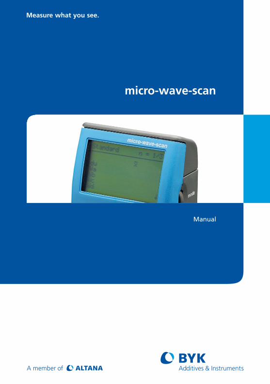
Manual
Patent pending 262 022 432 E 1111
BYK-Gardner GmbHLausitzer Str. 8D-82538 GeretsriedGermanyTel. 0-800-gardner (0-800-4273637) +49-8171-3493-0Fax +49-8171-3493-140
BYK - Gardner USA9104 Guilford RoadColumbia, MD 21046USAPhone 800-343-7721 301-483-6500Fax 800-394-8215 301-483-6555
www.byk.com/instruments
micro-wave-scan

2
Dear customer,thank you for having decided for a BYK-Gardner product. BYK-Gardner is committed to providing you with quality products and services. We offer complete system solutions to solve your problems in areas of gloss and physical properties. As the basis of our worldwide business, we strongly believe in total customer satisfaction. Therefore, in addition to our products, we offer many valueadded services: · Technical Sales Force· Technical & Application Support· Application and Technical Seminars· Repair&CertificationService BYK-Gardner is part of Altana AG and a direct subsidiary of BYK-Chemie GmbH, a leading supplier of additives for coatings and plastics. Together, we offer complete and unique solutions for you, our customer.
Thankyouforyourtrustandconfidence.Ifthereisanything we can do better to serve your needs, do not hesitate to let us know.
Your BYK-Gardner Team
3
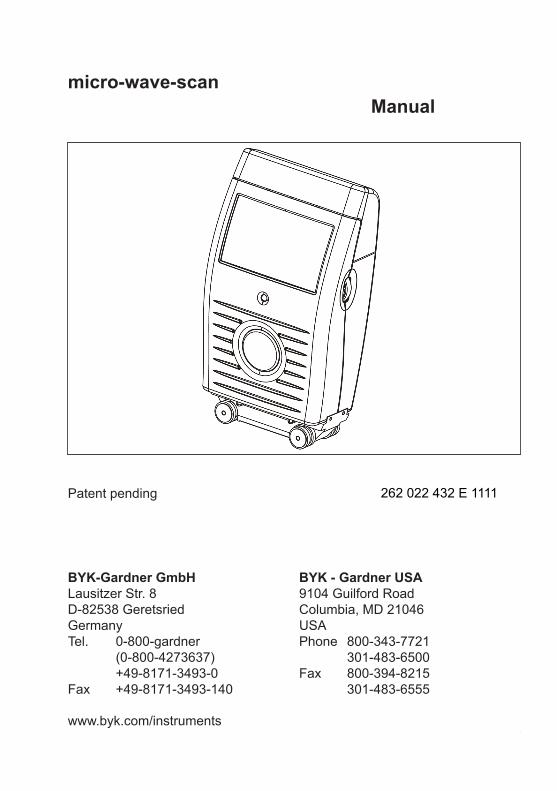
Table of content
1. Safety instructions ..................................................................................5
2. System description and Delivery notes ..............................................10
3. Power supply .........................................................................................143.1 Rechargeable battery pack .....................................................................153.2 Docking station power supply ...............................................................153.3 Charging the rechargeable battery ........................................................16
4. Controls ..................................................................................................17
5. Getting started .......................................................................................195.1 Turning the unit on and measuring .......................................................195.2 Display of measurement results ............................................................21
6. Testing the instrument ..........................................................................22
7. Menu operation ......................................................................................237.1 Navigation ................................................................................................237.2 Overview of main menu ..........................................................................247.3 Changing names and numbers ..............................................................25
8. Measure ..................................................................................................268.1 Measure ....................................................................................................268.2 MEMORY ...................................................................................................298.3 Organizer ..................................................................................................308.4 Memory with Parameter Input ................................................................32
9 Configuration .........................................................................................349.1 Number of Measurements ......................................................................359.2 Scanlength ...............................................................................................359.3 Scale .........................................................................................................369.4 Statistic .....................................................................................................39
10.AdvancedConfiguration ......................................................................4010.1 Correction ................................................................................................4010.2 Plausibility Control ..................................................................................4010.3 Interrupt ....................................................................................................41
Table of content
4
10.4 Input Parameter 2, 3 and Comment .......................................................4110.5 Input ID .....................................................................................................4110.6 Input Checkzone ......................................................................................41
11. Memory ...................................................................................................4211.1 ConfigurationNew ...................................................................................4211.2 ConfigurationChange .............................................................................4311.3 ConfigurationDelete ...............................................................................4311.4 Data View ..................................................................................................4411.5 Data Delete ...............................................................................................45
12. Setup ......................................................................................................4612.1 Beeper ......................................................................................................4612.2 Confirmwithmode ..................................................................................4612.3 Language ..................................................................................................4612.4 Info ............................................................................................................4712.5 Date / Time ...............................................................................................4712.6 Display Time ...........................................................................................47
13. Interface.................................................................................................4814.1 Connecting the measurement unit to a PC ...........................................48
14. Technical Data .......................................................................................49
15. Info and Error messages ......................................................................51
16. Cleaning and maintenance ...................................................................56Cleaning the test tile ........................................................................................57
17.ServiceandCertification .....................................................................58Service ...............................................................................................................58Service Centers for BYK-Gardner products ..................................................59
18. Copyright ...............................................................................................60
Table of content
5
1. Safety instructions• Beforeoperatingtheinstrumentthefirsttime,
please read the operating instructions and take particular notice of the safety instructions.
• Ifyouusetheunitandaccessoriesproperly,there are no hazards to fear.
• Thisproductisequippedwithsafetyfeatures.Nevertheless, read the safety warnings carefully and use the product only as described in these instructions to avoid accidental injury or damage.
• Noclaimsofproductliabilityorwarrantycanbe honored if the device is not operated in accordance with the operating instructions.
• Keeptheseinstructionsforfuturereference.
• Ifyoupassthisinstrumenttosomebodyelse,make sure to include these instructions.
Safety instructions
6
Safety instructions
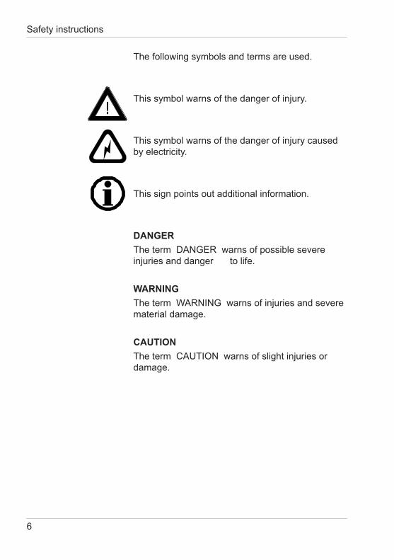
The following symbols and terms are used.
This symbol warns of the danger of injury.
This symbol warns of the danger of injury caused by electricity.
This sign points out additional information.
DANGERThe term DANGER warns of possible severe injuries and danger to life.
WARNINGThetermWARNINGwarnsofinjuriesandseverematerial damage.
CAUTIONThetermCAUTIONwarnsofslightinjuriesordamage.
7
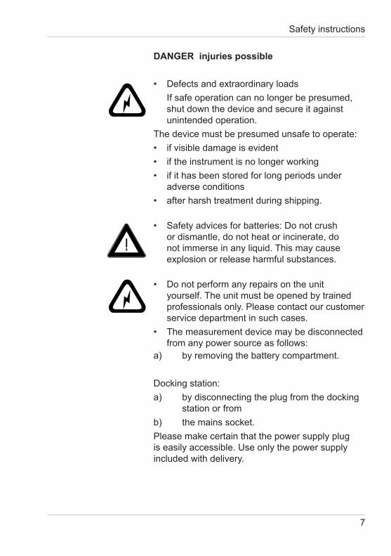
DANGER injuries possible
• Defectsandextraordinaryloads Ifsafeoperationcannolongerbepresumed,
shut down the device and secure it against unintended operation.
The device must be presumed unsafe to operate:• ifvisibledamageisevident• iftheinstrumentisnolongerworking• ifithasbeenstoredforlongperiodsunder
adverse conditions• afterharshtreatmentduringshipping.
• Safetyadvicesforbatteries:Donotcrushor dismantle, do not heat or incinerate, do not immerse in any liquid. This may cause explosion or release harmful substances.
• Donotperformanyrepairsontheunityourself. The unit must be opened by trained professionals only. Please contact our customer service department in such cases.
• Themeasurementdevicemaybedisconnectedfrom any power source as follows:
a) by removing the battery compartment.
Docking station:a) by disconnecting the plug from the docking station or fromb) the mains socket.Please make certain that the power supply plug is easily accessible. Use only the power supply included with delivery.
Safety instructions
8
Safety instructions
WARNING severe material damage
• Themeasurementunitconsistsofsensitiveoptical and electronic precision parts. Prevent it from being dropped, bumped or shaken!
• Avoidexposuretocontinuoushumidityandcon densation. Avoid splashing with water, chemicals or other liquids.
• Pleaseuseonlyaccessoriesthatareavailablefor the unit.
• Onlydevicesthatmeettherequirementsforlow voltage safety may be connected to the interface.
Great Britain:
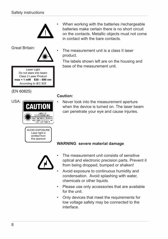
• Whenworkingwiththebatteries/rechargeablebatteries make certain there is no short circuit on the contacts. Metallic objects must not come in contact with the bare contacts.
• ThemeasurementunitisaclassIIlaserproduct.
The labels shown left are on the housing and base of the measurement unit.
Caution:• Neverlookintothemeasurementaperture
when the device is turned on. The laser beam can penetrate your eye and cause injuries.
(EN 60825)
USA:
Laser LightDo not stare into beamClass 2 Laser Product
max < 1 mW 630 – 690 nmAccordingtoIEC825
9
CAUTION material damage
• Donotallowanyforeignobjectstogetintothemeasurement opening.
• Donotexposetheunittodirectsunlightforextended periods of time. Do not store it in a hot or dusty environment. Use the instrument case for storage.
• RechargeableLi-Ionbatterypacks:Donotcharge at temperatures below 0°C. The allowable discharge temperature range is -20 to +60°C.
• Donotuseanyacetoneforcleaningtheunit! The unit housing is resistant to many solvents. For cleaning you should use a soft, moist cloth. Excessive dirt and dust can be removed with propanol.
• Incaseyouintendnottousetheinstrumentfora longer period of time, take out the batteries.
Additonal information on use:
• Youwillfindthetechnicaldataforallsystemcomponents on the respective manufacturer’s plates and in the section Technical Data
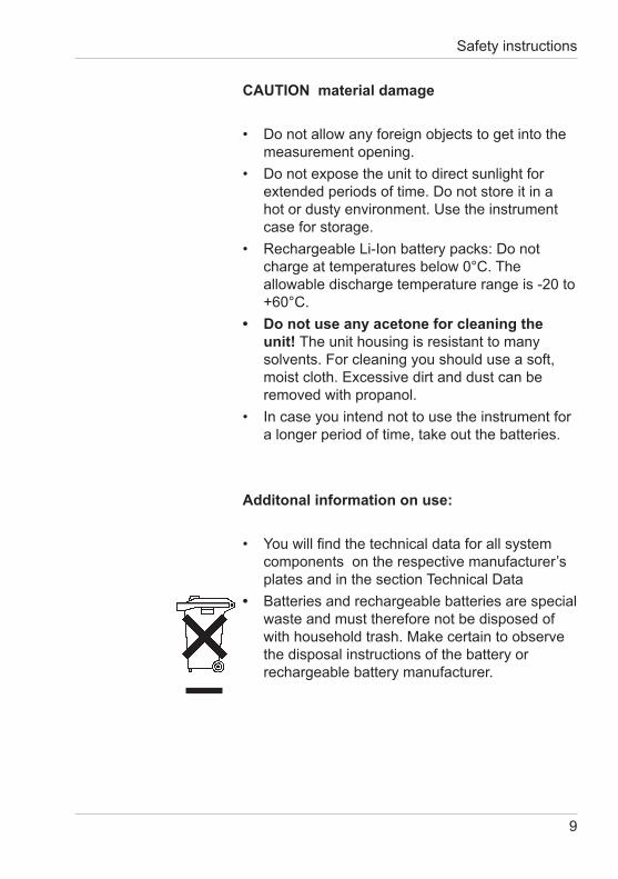
• Batteries and rechargeable batteries are special waste and must therefore not be disposed of with household trash. Make certain to observe the disposal instructions of the battery or rechargeable battery manufacturer.
Safety instructions
10
System description and Delivery notes
2. System description and Delivery notesPlease read the instruction manual before using the instrument and note the safety instructions.The measurement unit is used to evaluate the appearanceofhigh-qualitysurfaces(OrangePeel,DOI).The measurement system consists of the portable measurement device, docking station and the smart-chart program.
Depending on the application, the system can be used in various ways, from single measurements in R & D up to routine quality control procedures (e.g. automobile).
Inordertoguaranteeaflexibledataanalysis,itisessentialtoallocatethedatatoaclearlydefinedobject(identification).
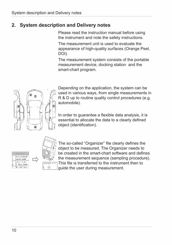
Theso-called“Organizer”fileclearlydefinestheobjecttobemeasured.TheOrganizerneedstobecreatedinthesmart-chartsoftwareanddefinesthe measurement sequence (sampling procedure). Thisfileistransferredtotheinstrumentthentoguide the user during measurement.
Organizer
Center Hood n=1/3 L 7.6 S 18.3
11
The saved results are transferred to the PC and displayed as a QC report.The data is saved in a database for further analysis over time. Pre-prepared test reports in the smart-chart software assist in analyzing the data.
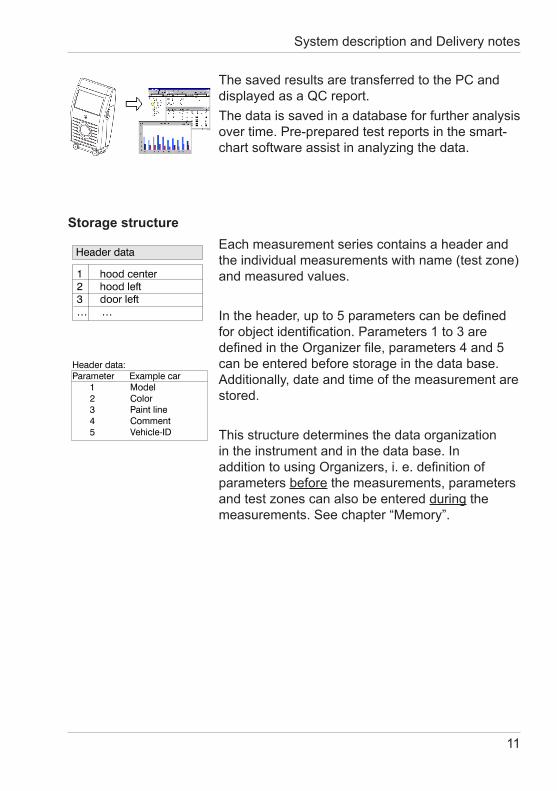
Storage structureEach measurement series contains a header and the individual measurements with name (test zone) and measured values.
Intheheader,upto5parameterscanbedefinedforobjectidentification.Parameters1to3aredefinedintheOrganizerfile,parameters4and5can be entered before storage in the data base. Additionally, date and time of the measurement are stored.
This structure determines the data organization intheinstrumentandinthedatabase.InadditiontousingOrganizers,i.e.definitionofparameters before the measurements, parameters and test zones can also be entered during the measurements.Seechapter“Memory”.
System description and Delivery notes
12
System description and Delivery notes
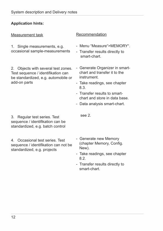
Application hints:
Measurement task
1. Single measurements, e.g. occasional sample-measurements
2.Objectswithseveraltestzones.Testsequence/identifikationcanbe standardized, e.g. automobile or add-on parts
3. Regular test series. Test sequence/identifikationcanbestandardized, e.g. batch control 4.Occasionaltestseries.Testsequence/identifikationcannotbestandardized, e.g. projects
Recommendation
-Menu“Measure“>MEMORY“.- Transfer results directly to smart-chart.
-GenerateOrganizerinsmart- chart and transfer it to the instrument.- Take readings, see chapter 8.3.- Transfer results to smart- chart and store in data base.- Data analysis smart-chart. see 2. - Generate new Memory (chapterMemory,Config. New).- Take readings, see chapter 8.2.- Transfer results directly to smart-chart.
13
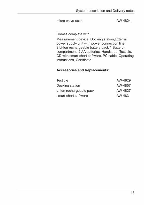
micro-wave-scan AW-4824 Comes complete with:Measurement device, Docking station,External power supply unit with power connection line, 2Li-Ionrechargeablebatterypack,1Battery-compartment, 2 AA batteries, Handstrap, Test tile, CDwithsmart-chartsoftware,PCcable,Operatinginstructions,Certificate
Accessories and Replacements:
Test tile AW-4829Docking station AW-4857Li-Ionrechargeablepack AW-4827smart-chart software AW-4831
System description and Delivery notes
14
Power supply
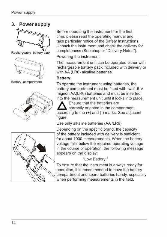
3. Power supplyBeforeoperatingtheinstrumentforthefirsttime, please read the operating manual and takeparticularnoticeoftheSafetyInstructions.Unpack the instrument and check the delivery for completeness(Seechapter“DeliveryNotes”).Powering the instrumentThe measurement unit can be operated either with rechargeable battery pack included with delivery or with AA (LR6) alkaline batteries.Battery:To operate the instrument using batteries, the batterycompartmentmustbefittedwithtwo1.5-Vmignon AA(LR6) batteries and must be inserted into the measurement unit until it locks into place. Ensure that the batteries are correctly oriented in the compartment according to the (+) and (-) marks. See adjacent figure.Use only alkaline batteries (AA /LR6)!Dependingonthespecificbrand,thecapacityofthebatteryincludedwithdeliveryissufficientfor about 1000 measurements. When the battery voltage falls below the required operating voltage in the course of operation, the following message appears on the display: “LowBattery!”To ensure that the instrument is always ready for operation, it is recommended to have the battery compartment and spare batteries handy, especially whenperformingmeasurementsinthefield.
Rechargeable battery pack
Battery compartment
15
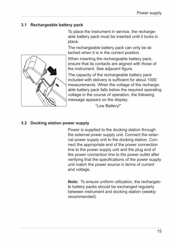
3.1 Rechargeable battery packTo place the instrument in service, the recharge-able battery pack must be inserted until it locks in place.The rechargeable battery pack can only be at-tached when it is in the correct position.When inserting the rechargeable battery pack, ensure that its contacts are aligned with those of theinstrument.Seeadjacentfigure.The capacity of the rechargeable battery pack includedwithdeliveryissufficientforabout1000measurements. When the voltage of the recharge-able battery pack falls below the required operating voltage in the course of operation, the following message appears on the display: “LowBattery!”
3.2 Docking station power supplyPower is supplied to the docking station through the external power supply unit. Connect the exter-nal power supply unit to the docking station. Con-nect the appropriate end of the power connection line to the power supply unit and the plug end of the power connection line to the power outlet after verifyingthatthespecificationsofthepowersupplyunit match the power source in terms of current and voltage.
Note: To ensure uniform utilization, the rechargeb-le battery packs should be exchanged regularly between instrument and docking station (weekly recommended).
Power supply
16
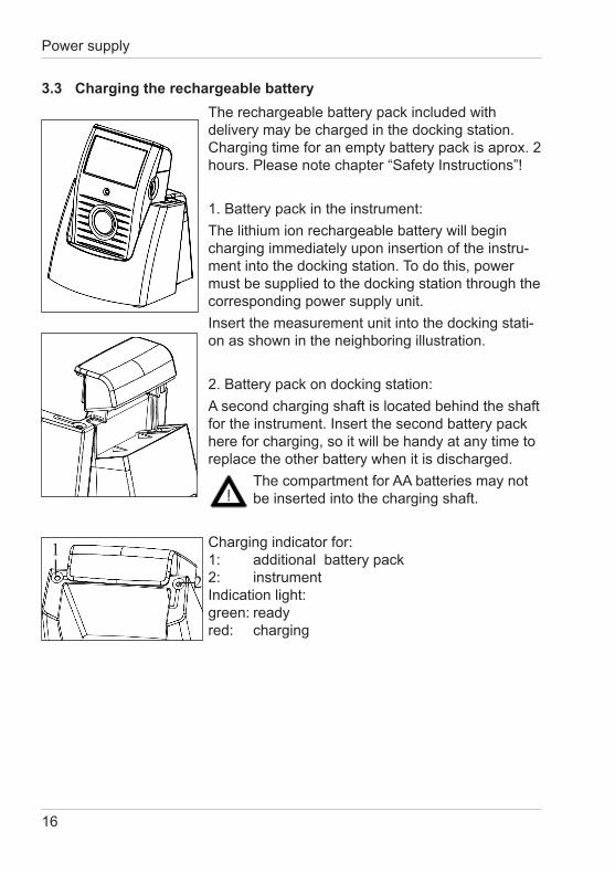
3.3 Charging the rechargeable batteryThe rechargeable battery pack included with delivery may be charged in the docking station. Charging time for an empty battery pack is aprox. 2 hours.Pleasenotechapter“SafetyInstructions”!
1. Battery pack in the instrument:The lithium ion rechargeable battery will begin charging immediately upon insertion of the instru-ment into the docking station. To do this, power must be supplied to the docking station through the corresponding power supply unit.Insertthemeasurementunitintothedockingstati-on as shown in the neighboring illustration.
2. Battery pack on docking station:A second charging shaft is located behind the shaft fortheinstrument.Insertthesecondbatterypackhere for charging, so it will be handy at any time to replace the other battery when it is discharged. The compartment for AA batteries may not be inserted into the charging shaft.
Charging indicator for: 1: additional battery pack 2: instrument Indicationlight: green: ready red: charging
Power supply
1
2
17
Controls
4. Controls
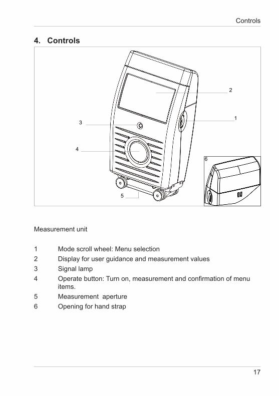
Measurement unit
1 Mode scroll wheel: Menu selection2 Display for user guidance and measurement values3 Signal lamp4 Operatebutton:Turnon,measurementandconfirmationofmenu items.5 Measurement aperture6 Openingforhandstrap
1
2
3
4
5
6
18
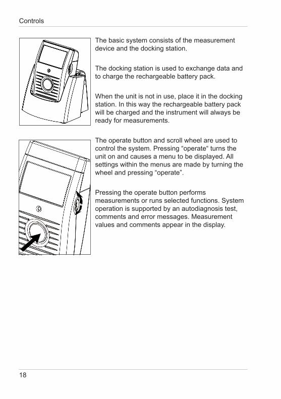
The basic system consists of the measurement device and the docking station.
The docking station is used to exchange data and to charge the rechargeable battery pack.
When the unit is not in use, place it in the docking station.Inthiswaytherechargeablebatterypackwill be charged and the instrument will always be ready for measurements.
The operate button and scroll wheel are used to control the system. Pressing “operate“ turns the unit on and causes a menu to be displayed. All settings within the menus are made by turning the wheelandpressing“operate”.
Pressing the operate button performs measurements or runs selected functions. System operation is supported by an autodiagnosis test, comments and error messages. Measurement values and comments appear in the display.
Controls
19
Getting started
5. Getting started
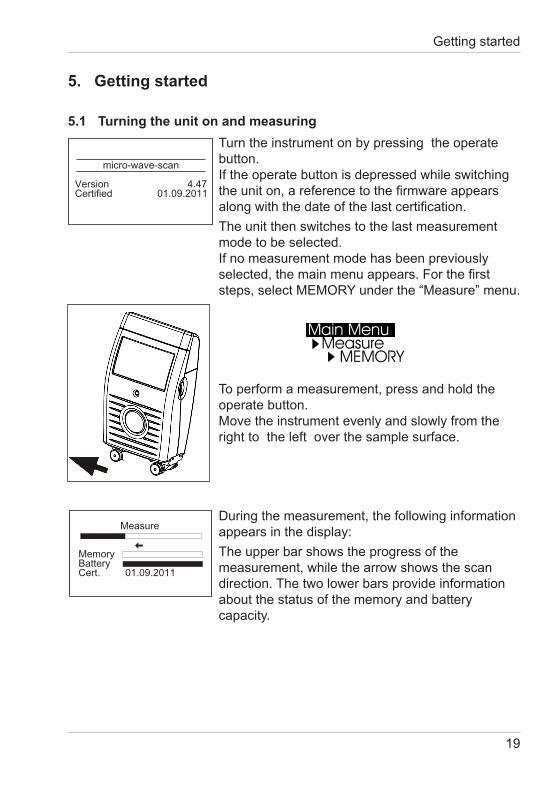
5.1 Turning the unit on and measuringTurn the instrument on by pressing the operate button. Iftheoperatebuttonisdepressedwhileswitchingtheuniton,areferencetothefirmwareappearsalongwiththedateofthelastcertification.The unit then switches to the last measurement mode to be selected. Ifnomeasurementmodehasbeenpreviouslyselected,themainmenuappears.Forthefirststeps,selectMEMORYunderthe“Measure”menu.
To perform a measurement, press and hold the operate button. Move the instrument evenly and slowly from the right to the left over the sample surface.
During the measurement, the following information appears in the display:The upper bar shows the progress of the measurement, while the arrow shows the scan direction. The two lower bars provide information about the status of the memory and battery capacity.
Measure
MemoryBatteryCert. 01.09.2011
micro-wave-scan
Version 4.47Certified 01.09.2011
20
Getting started
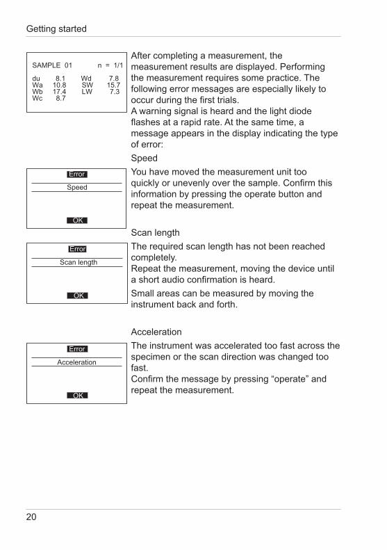
After completing a measurement, the measurement results are displayed. Performing the measurement requires some practice. The following error messages are especially likely to occurduringthefirsttrials. A warning signal is heard and the light diode flashesatarapidrate.Atthesametime,amessage appears in the display indicating the type of error:SpeedYou have moved the measurement unit too quicklyorunevenlyoverthesample.Confirmthisinformation by pressing the operate button and repeat the measurement.
Scan lengthThe required scan length has not been reached completely. Repeat the measurement, moving the device until ashortaudioconfirmationisheard.Small areas can be measured by moving the instrument back and forth.
AccelerationThe instrument was accelerated too fast across the specimen or the scan direction was changed too fast. Confirmthemessagebypressing“operate”andrepeat the measurement.
Scan length
Error
OK
Acceleration
Error
OK
Speed
Error
OK
SAMPLE 01 n = 1/1
du 8.1 Wd 7.8Wa 10.8 SW 15.7Wb 17.4 LW 7.3Wc 8.7
21
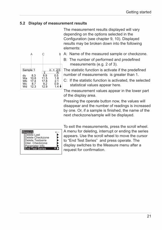
5.2 Display of measurement resultsThe measurement results displayed will vary depending on the options selected in the Configuration(seechapter9,10).Displayedresults may be broken down into the following elements:A: Name of the measured sample or checkzone.B:Thenumberofperformedandpredefined measurements (e.g. 2 of 3). Thestatisticfunctionisactivateifthepredefinednumber of measurements is greater than 1. C:Ifthestatisticfunctionisactivated,theselected statistical values appear here.The measurement values appear in the lower part of the display area.Pressing the operate button now, the values will disappear and the number of readings is increased byone.Or,ifasampleisfinished,thenameofthenext checkzone/sample will be displayed.
To exit the measurements, press the scroll wheel. A menu for deleting, interrupt or ending the series appears. Use the scroll wheel to move the cursor to“EndTestSeries”andpressoperate.Thedisplay switches to the Measure menu after a requestforconfirmation.
Getting started
Measure
End Test Series
Delete LastDelete CheckzoneDelete TestserieInter. CheckzoneParameter Info
*
22
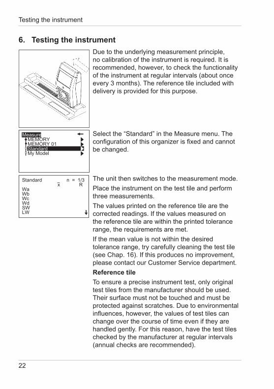
6. Testing the instrumentDue to the underlying measurement principle, nocalibrationoftheinstrumentisrequired.Itisrecommended, however, to check the functionality of the instrument at regular intervals (about once every 3 months). The reference tile included with delivery is provided for this purpose.
Selectthe“Standard”intheMeasuremenu.Theconfigurationofthisorganizerisfixedandcannotbe changed.
The unit then switches to the measurement mode. Place the instrument on the test tile and perform three measurements.The values printed on the reference tile are the correctedreadings.Ifthevaluesmeasuredonthe reference tile are within the printed tolerance range, the requirements are met. Ifthemeanvalueisnotwithinthedesiredtolerance range, try carefully cleaning the test tile (seeChap.16).Ifthisproducesnoimprovement,please contact our Customer Service department.Reference tileTo ensure a precise instrument test, only original test tiles from the manufacturer should be used. Their surface must not be touched and must be protected against scratches. Due to environmental influences,however,thevaluesoftesttilescanchange over the course of time even if they are handled gently. For this reason, have the test tiles checked by the manufacturer at regular intervals (annual checks are recommended).
Testing the instrument
Standard n = 1/3x R
WaWbWcWdSWLW
Measure
Standard
MEMORYMEMORY 01
My Model
23
Menu operation
7. Menu operation
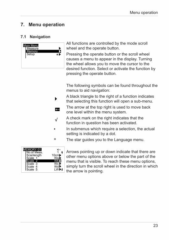
7.1 NavigationAll functions are controlled by the mode scroll wheel and the operate button.Pressing the operate button or the scroll wheel causes a menu to appear in the display. Turning the wheel allows you to move the cursor to the desired function. Select or activate the function by pressing the operate button.
The following symbols can be found throughout the menus to aid navigation:A black triangle to the right of a function indicates that selecting this function will open a sub-menu.The arrow at the top right is used to move back one level within the menu system.A check mark on the right indicates that the function in question has been activated.Insubmenuswhichrequireaselection,theactualsetting is indicated by a dot. The star guides you to the Language menu.
Arrows pointing up or down indicate that there are other menu options above or below the part of the menu that is visible. To reach these menu options, simply turn the scroll wheel in the direction in which the arrow is pointing.
*
•
24
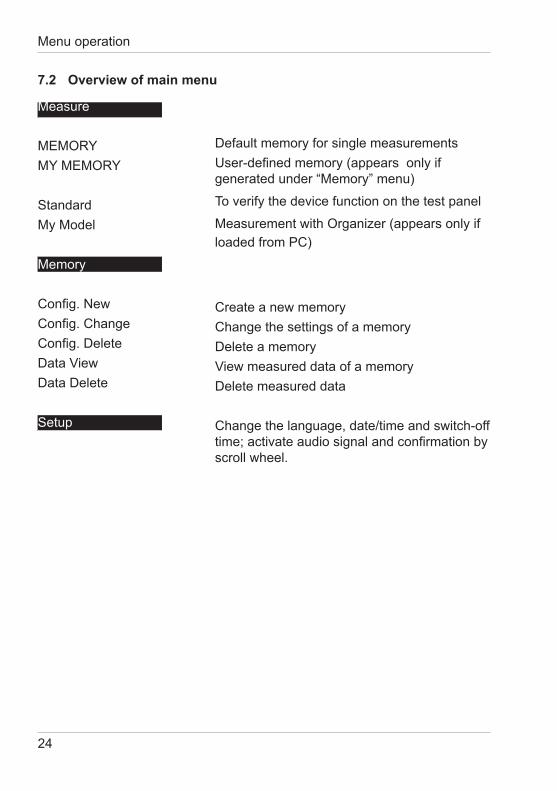
Measure
MEMORYMYMEMORY
StandardMy Model
Memory
Config.NewConfig.ChangeConfig.DeleteDataViewData Delete
Setup
Default memory for single measurementsUser-definedmemory(appearsonlyifgeneratedunder“Memory”menu)
To verify the device function on the test panel
MeasurementwithOrganizer(appearsonlyifloaded from PC) Create a new memoryChange the settings of a memory Delete a memory ViewmeasureddataofamemoryDelete measured data
Change the language, date/time and switch-off time;activateaudiosignalandconfirmationbyscroll wheel.
7.2 Overview of main menu
Menu operation
25
Menu operation
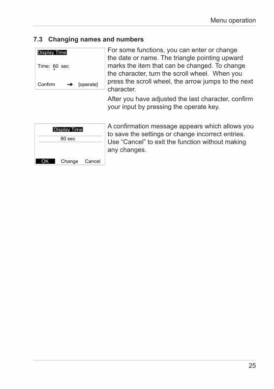
7.3 Changing names and numbersFor some functions, you can enter or change the date or name. The triangle pointing upward marks the item that can be changed. To change the character, turn the scroll wheel. When you press the scroll wheel, the arrow jumps to the next character.Afteryouhaveadjustedthelastcharacter,confirmyour input by pressing the operate key.
Aconfirmationmessageappearswhichallowsyouto save the settings or change incorrect entries. Use“Cancel”toexitthefunctionwithoutmakingany changes.
26
Measure
8. Measure
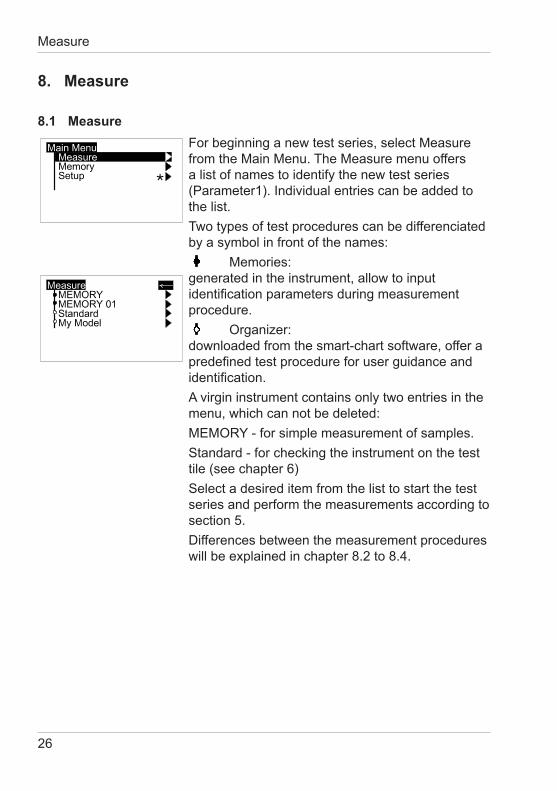
8.1 MeasureFor beginning a new test series, select Measure from the Main Menu. The Measure menu offers a list of names to identify the new test series (Parameter1).Individualentriescanbeaddedtothe list.Two types of test procedures can be differenciated by a symbol in front of the names: Memories: generated in the instrument, allow to input identificationparametersduringmeasurementprocedure. Organizer: downloaded from the smart-chart software, offer a predefinedtestprocedureforuserguidanceandidentification.A virgin instrument contains only two entries in the menu, which can not be deleted:MEMORY-forsimplemeasurementofsamples.Standard - for checking the instrument on the test tile (see chapter 6)Select a desired item from the list to start the test series and perform the measurements according to section 5.Differences between the measurement procedures will be explained in chapter 8.2 to 8.4.
27
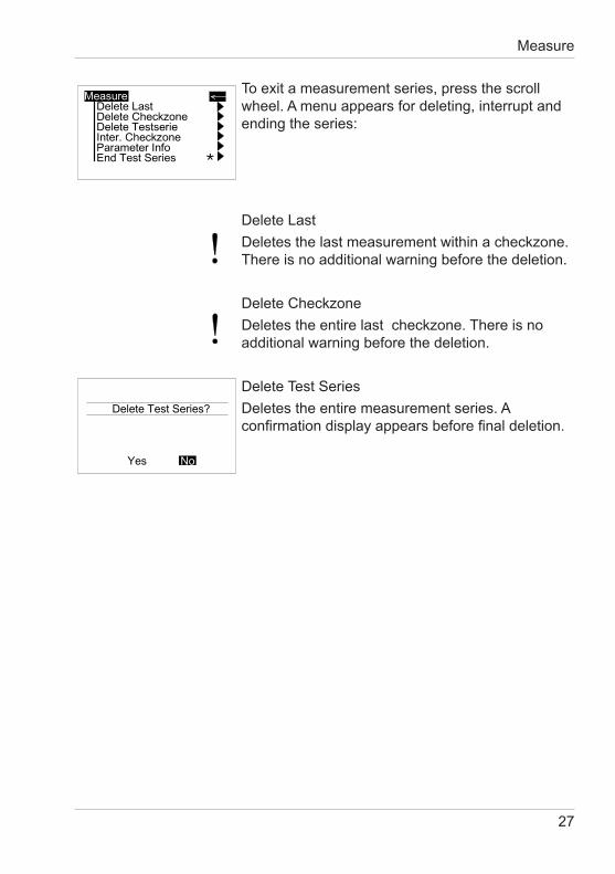
To exit a measurement series, press the scroll wheel. A menu appears for deleting, interrupt and ending the series:
Delete LastDeletes the last measurement within a checkzone.There is no additional warning before the deletion.
Delete CheckzoneDeletes the entire last checkzone. There is no additional warning before the de letion.
Delete Test SeriesDeletes the entire measurement series. A confirmationdisplayappearsbeforefinaldeletion.
Measure
28
Measure
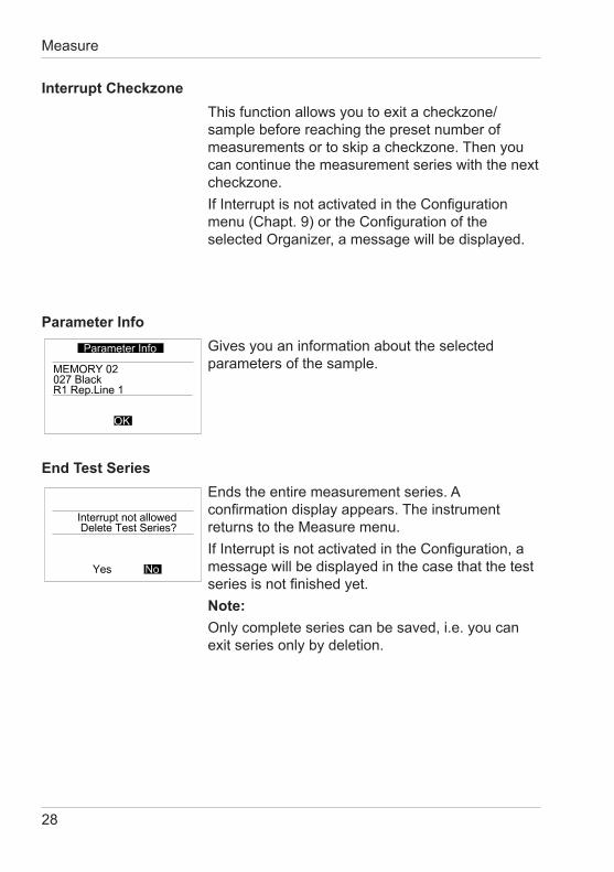
Interrupt CheckzoneThis function allows you to exit a checkzone/sample before reaching the preset number of measurements or to skip a checkzone. Then you can continue the measurement series with the next checkzone.IfInterruptisnotactivatedintheConfigurationmenu(Chapt.9)ortheConfigurationoftheselectedOrganizer,amessagewillbedisplayed.
Parameter InfoGives you an information about the selected parameters of the sample.
End Test SeriesEnds the entire measurement series. A confirmationdisplayappears.Theinstrumentreturns to the Measure menu.IfInterruptisnotactivatedintheConfiguration,amessage will be displayed in the case that the test seriesisnotfinishedyet.Note:Onlycompleteseriescanbesaved,i.e.youcanexit series only by deletion.
29
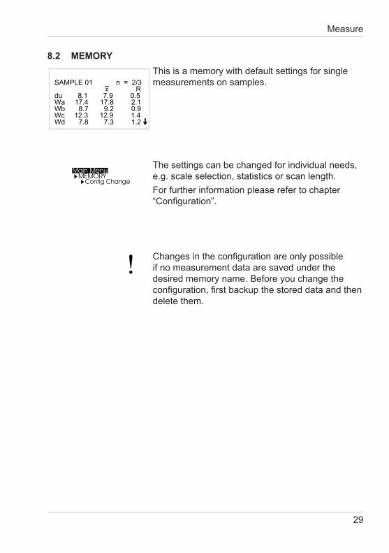
8.2 MEMORYThis is a memory with default settings for single measurements on samples.
The settings can be changed for individual needs, e.g. scale selection, statistics or scan length.For further information please refer to chapter “Configuration”.
Changesintheconfigurationareonlypossibleif no measurement data are saved under the desired memory name. Before you change the configuration,firstbackupthestoreddataandthendelete them.
Measure
30
Measure
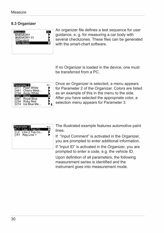
8.3 OrganizerAnorganizerfiledefinesatestsequenceforuserguidance, e. g. for measuring a car body with severalcheckzones.Thesefilescanbegeneratedwith the smart-chart software.
IfnoOrganizerisloadedinthedevice,onemustbe transferred from a PC.
OnceanOrganizerisselected,amenuappearsforParameter2oftheOrganizer.Colorsarelistedas an example of this in the menu to the side. After you have selected the appropriate color, a selection menu appears for Parameter 3.
The illustrated example features automotive paint lines.If“InputComment”isactivatedintheOrganizer,you are prompted to enter additional information.If“InputID”isactivatedintheOrganizer,youarepromptedtoenteracode,e.g.thevehicleID.Upondefinitionofallparameters,thefollowingmeasurementseriesisidentifiedandtheinstrument goes into measurement mode.
31
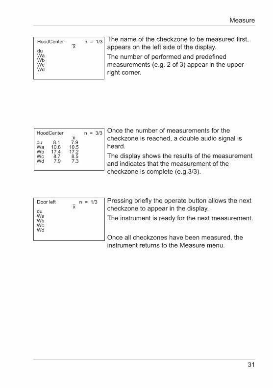
Thenameofthecheckzonetobemeasuredfirst,appears on the left side of the display.Thenumberofperformedandpredefinedmeasurements (e.g. 2 of 3) appear in the upper right corner.
Oncethenumberofmeasurementsforthecheckzone is reached, a double audio signal is heard.The display shows the results of the measurement and indicates that the measurement of the checkzone is complete (e.g.3/3).
Pressingbrieflytheoperatebuttonallowsthenextcheckzone to appear in the display.The instrument is ready for the next measurement.
Onceallcheckzoneshavebeenmeasured,theinstrument returns to the Measure menu.
Measure
HoodCenter n = 1/3x
duWaWbWcWd
HoodCenter n = 3/3x
du 8.1 7.9Wa 10.8 10.5Wb 17.4 17.2Wc 8.7 8.5Wd 7.9 7.3
Door left n = 1/3x
duWaWbWcWd
32
Measure
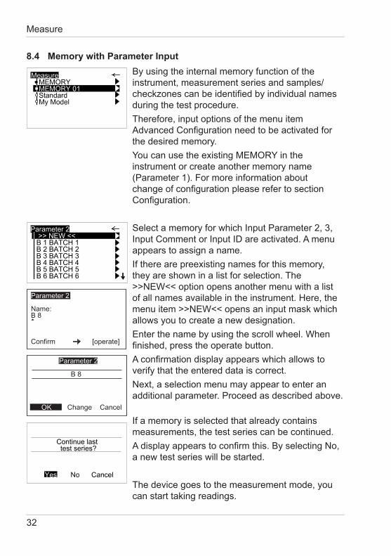
8.4 Memory with Parameter InputBy using the internal memory function of the instrument, measurement series and samples/checkzonescanbeidentifiedbyindividualnamesduring the test procedure.Therefore, input options of the menu item AdvancedConfigurationneedtobeactivatedforthe desired memory.YoucanusetheexistingMEMORYintheinstrument or create another memory name (Parameter 1). For more information about changeofconfigurationpleaserefertosectionConfiguration.
SelectamemoryforwhichInputParameter2,3,InputCommentorInputIDareactivated.Amenuappears to assign a name.Iftherearepreexistingnamesforthismemory,they are shown in a list for selection. The >>NEW<< option opens another menu with a list of all names available in the instrument. Here, the menu item >>NEW<< opens an input mask which allows you to create a new designation.Enter the name by using the scroll wheel. When finished,presstheoperatebutton.Aconfirmationdisplayappearswhichallowstoverify that the entered data is correct.Next, a selection menu may appear to enter an additional parameter. Proceed as described above. Ifamemoryisselectedthatalreadycontainsmeasurements, the test series can be continued. Adisplayappearstoconfirmthis.ByselectingNo,a new test series will be started.
The device goes to the measurement mode, you can start taking readings.
Parameter 2
Name:B 8
Confirm [operate]
B 8
Change Cancel
Parameter 2
OK
33
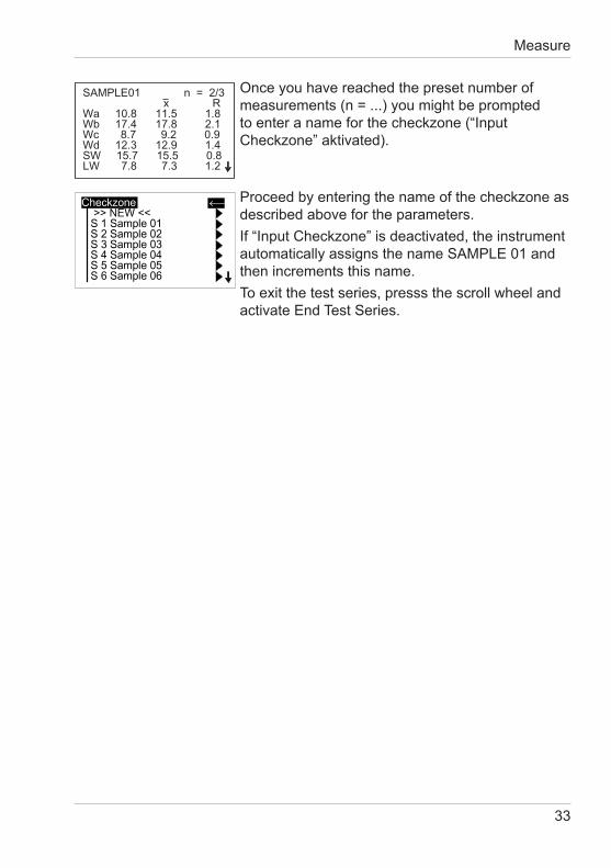
Onceyouhavereachedthepresetnumberofmeasurements (n = ...) you might be prompted toenteranameforthecheckzone(“InputCheckzone”aktivated).
Proceed by entering the name of the checkzone as described above for the parameters.If“InputCheckzone”isdeactivated,theinstrumentautomatically assigns the name SAMPLE 01 and then increments this name.To exit the test series, presss the scroll wheel and activate End Test Series.
Measure
SAMPLE01 n = 2/3x R
Wa 10.8 11.5 1.8Wb 17.4 17.8 2.1Wc 8.7 9.2 0.9Wd 12.3 12.9 1.4SW 15.7 15.5 0.8LW 7.8 7.3 1.2
34
Configuration
9 Configuration
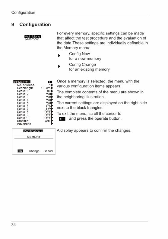
Foreverymemory,specificsettingscanbemadethat affect the test procedure and the evaluation of thedata.Thesesettingsareindividuallydefinableinthe Memory menu: ConfigNew for a new memory ConfigChange for an existing memory
Onceamemoryisselected,themenuwiththevariousconfigurationitemsappears.The complete contents of the menu are shown in the neighboring illustration.The current settings are displayed on the right side next to the black triangles. To exit the menu, scroll the cursor to and press the operate button.
Adisplayappearstoconfirmthechanges.
35
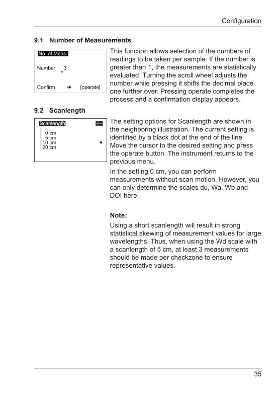
9.1 Number of MeasurementsThis function allows selection of the numbers of readingstobetakenpersample.Ifthenumberisgreater than 1, the measurements are statistically evaluated. Turning the scroll wheel adjusts the number while pressing it shifts the decimal place one further over. Pressing operate completes the processandaconfirmationdisplayappears.
9.2 ScanlengthThe setting options for Scanlength are shown in the neighboring illustration. The current setting is identifiedbyablackdotattheendoftheline. Move the cursor to the desired setting and press the operate button. The instrument returns to the previous menu.Inthesetting0cm,youcanperformmeasurements without scan motion. However, you can only determine the scales du, Wa, Wb and DOIhere.
Note:Using a short scanlength will result in strong statistical skewing of measurement values for large wavelengths. Thus, when using the Wd scale with a scanlength of 5 cm, at least 3 measurements should be made per checkzone to ensure representative values.
Configuration
Scanlength
0 cm5 cm
10 cm20 cm
l
36
Configuration
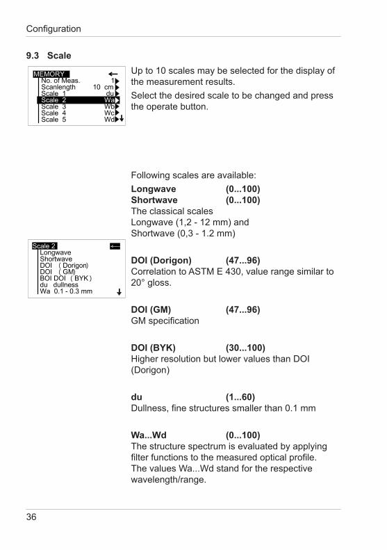
9.3 ScaleUp to 10 scales may be selected for the display of the measurement results.Select the desired scale to be changed and press the operate button.
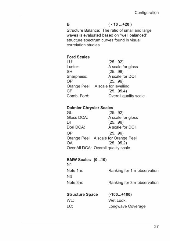
Following scales are available:Longwave (0...100) Shortwave (0...100) The classical scales Longwave (1,2 - 12 mm) and Shortwave (0,3 - 1.2 mm)
DOI (Dorigon) (47...96) Correlation to ASTM E 430, value range similar to 20° gloss.
DOI (GM) (47...96) GMspecification
DOI (BYK) (30...100) HigherresolutionbutlowervaluesthanDOI(Dorigon)
du (1...60) Dullness,finestructuressmallerthan0.1mm
Wa...Wd (0...100) The structure spectrum is evaluated by applying filterfunctionstothemeasuredopticalprofile.The values Wa...Wd stand for the respective wavelength/range.
37
B ( - 10 ...+20 )Structure Balance: The ratio of small and large waves is evaluated based on “well balanced“ structure spectrum curves found in visual correlation studies.
Ford Scales LU (25...92) Luster: A scale for gloss SH (25...96) Sharpness: AscaleforDOI OP (25...96) OrangePeel: Ascaleforlevelling CF (25...95.4) Comb.Ford: Overallqualityscale
Daimler Chrysler Scales GL (25...92) Gloss DCA: A scale for gloss DI (25...96) DoriDCA: AscaleforDOIOP (25...96) OrangePeel: AscaleforOrangePeel OA (25...95.2) OverAllDCA:Overallqualityscale
BMW Scales (0...10) N1Note 1m: Ranking for 1m observationN3Note 3m: Ranking for 3m observation
Structure Space (-100...+100)WL: Wet Look LC: Longwave Coverage
Configuration
38
Configuration
Rating (3...10.5) OrangePeelbasedonACTpanels
Tension (6...24,5) ScaleforOrangePeel
GM-Tension (6...21) GMspecification
MB-Tension (6...20) MercedesBenzspecification
H-Tension (0...20) Hondaspecification
P-Tension (6...20) Hondaspecification
Hada (1...6) NoteforOrangePeel(outdated)
CR-overall (6...100) Ford correlation (outdated)
OFF Turns the Scale off.
39
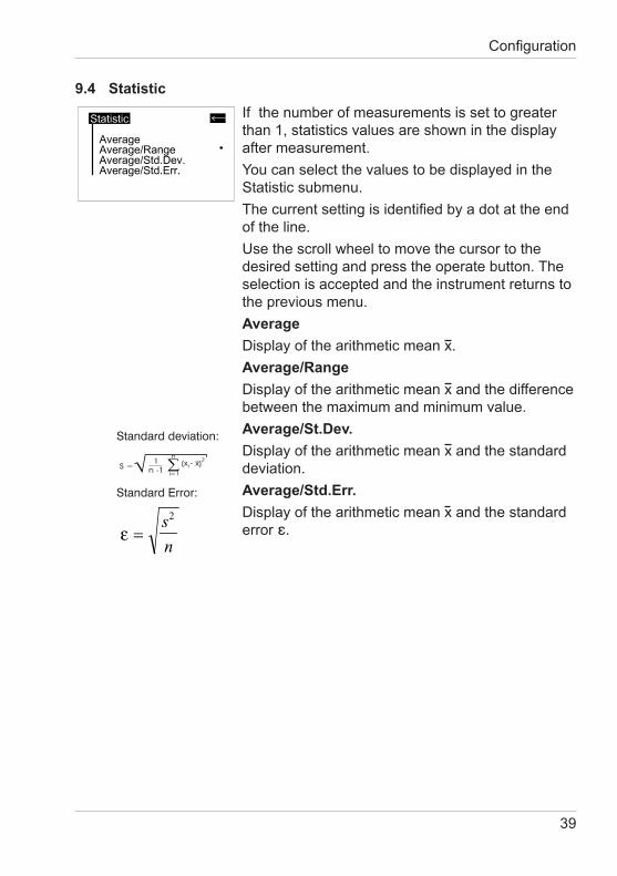
9.4 StatisticIfthenumberofmeasurementsissettogreaterthan 1, statistics values are shown in the display after measurement.You can select the values to be displayed in the Statistic submenu.Thecurrentsettingisidentifiedbyadotattheendof the line.Use the scroll wheel to move the cursor to the desired setting and press the operate button. The selection is accepted and the instrument returns to the previous menu.AverageDisplay of the arithmetic mean x.Average/RangeDisplay of the arithmetic mean x and the difference between the maximum and minimum value.Average/St.Dev.Display of the arithmetic mean x and the standard deviation.Average/Std.Err.Display of the arithmetic mean x and the standard error .
Standard deviation:
Standard Error:
Configuration
ε =s
n
2
40
AdvancedConfiguration
10.AdvancedConfiguration
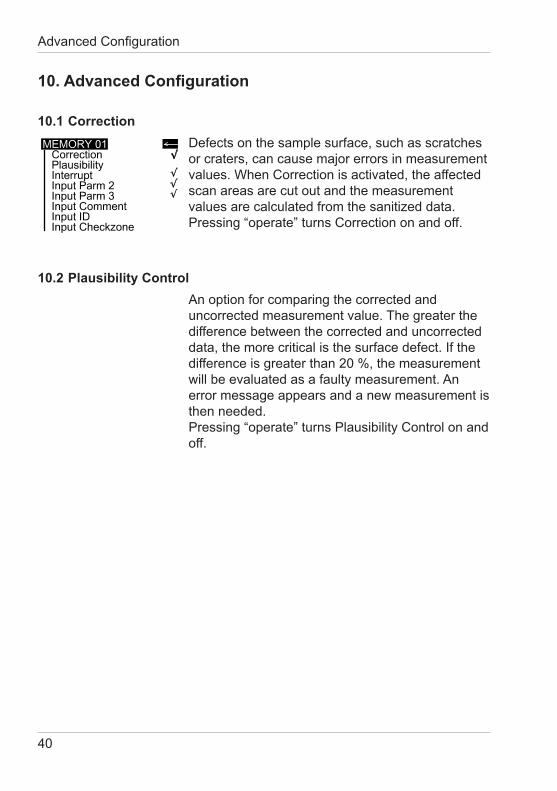
10.1 CorrectionDefects on the sample surface, such as scratches or craters, can cause major errors in measurement values. When Correction is activated, the affected scan areas are cut out and the measurement values are calculated from the sanitized data. Pressing“operate”turnsCorrectiononandoff.
10.2 Plausibility ControlAn option for comparing the corrected and uncorrected measurement value. The greater the difference between the corrected and uncorrected data,themorecriticalisthesurfacedefect.Ifthedifference is greater than 20 %, the measurement will be evaluated as a faulty measurement. An error message appears and a new measurement is then needed. Pressing“operate”turnsPlausibilityControlonandoff.
41
10.3 InterruptIfstatisticisactivatedintheconfigurationoftheselected memory (n > 1), you can interrupt a checkzone (sample) before reaching the preset number of measurements.
10.4 Input Parameter 2, 3 and CommentWhen active, these parameters allow to assign individualnamesforidentificationofanewtestseries.
10.5 Input IDWhen this function is active, you can enter an identificationcodee.g.vehicleIDnumberforeachnew test series.
10.6 Input CheckzoneWhen active, you can enter a designation for every sample during a test series. When deactivated, the instrument automatically assigns sample names incrementally, beginning with SAMPLE 01.
AdvancedConfiguration
42
Memory
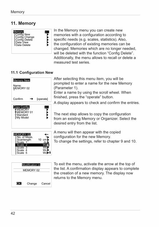
11. MemoryIntheMemorymenuyoucancreatenewmemorieswithaconfigurationaccordingtospecificneeds(e.g.scales,statistics).Also,theconfigurationofexistingmemoriescanbechanged. Memories which are no longer needed, willbedeletedwiththefunction“ConfigDelete”. Additionally, the menu allows to recall or delete a measured test series.
11.1ConfigurationNewAfter selecting this menu item, you will be prompted to enter a name for the new Memory (Parameter 1). Enter a name by using the scroll wheel. When finished,pressthe“operate”button.Adisplayappearstocheckandconfirmtheentries.
ThenextstepallowstocopytheconfigurationfromanexistingMemoryorOrganizer.Selectthedesired entry from the list.
A menu will then appear with the copied configurationforthenewMemory. To change the settings, refer to chapter 9 and 10.
To exit the menu, activate the arrow at the top of thelist.Aconfirmationdisplayappearstocompletethe creation of a new memory. The display now returns to the Memory menu.
43
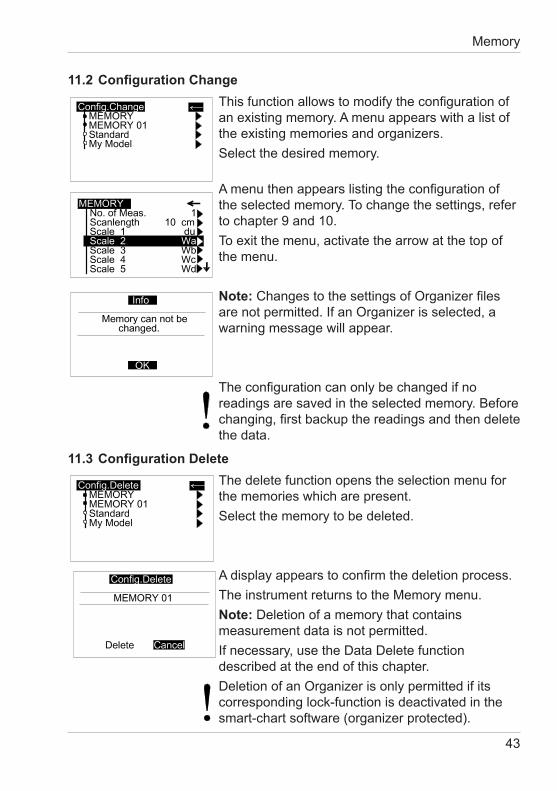
11.2ConfigurationChangeThisfunctionallowstomodifytheconfigurationofan existing memory. A menu appears with a list of the existing memories and organizers.Select the desired memory.
Amenuthenappearslistingtheconfigurationofthe selected memory. To change the settings, refer to chapter 9 and 10.To exit the menu, activate the arrow at the top of the menu.
Note:ChangestothesettingsofOrganizerfilesarenotpermitted.IfanOrganizerisselected,awarning message will appear.
Theconfigurationcanonlybechangedifnoreadings are saved in the selected memory. Before changing,firstbackupthereadingsandthendeletethe data.
11.3ConfigurationDeleteThe delete function opens the selection menu for the memories which are present.Select the memory to be deleted.
Adisplayappearstoconfirmthedeletionprocess.The instrument returns to the Memory menu.Note: Deletion of a memory that contains measurement data is not permitted.Ifnecessary,usetheDataDeletefunctiondescribed at the end of this chapter.DeletionofanOrganizerisonlypermittedifitscorresponding lock-function is deactivated in the smart-chart software (organizer protected).
Memory
44
Memory
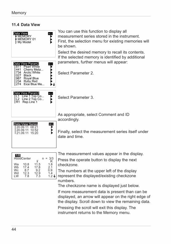
The measurement values appear in the display.Press the operate button to display the next checkzone.The numbers at the upper left of the display represent the displayed/existing checkzone numbers. The checkzone name is displayed just below.Ifmoremeasurementdataispresentthancanbedisplayed, an arrow will appear on the right edge of the display. Scroll down to view the remaining data.Pressing the scroll will exit this display. The instrument returns to the Memory menu.
11.4 Data ViewYou can use this function to display all measurement series stored in the instrument. First, the selection menu for existing memories will be shown.Select the desired memory to recall its contents. Iftheselectedmemoryisidentifiedbyadditionalparameters, further menus will appear:
Select Parameter 2.
Select Parameter 3.
Asappropriate,selectCommentandIDaccordingly.
Finally, select the measurement series itself under date and time.
Data View Series20.09.11 08:2120.09.11 10:5221.09.11 15:20
HoodCenter n = 3/3x R
Wa 10.8 11.5 1.8Wb 17.4 17.8 2.1Wc 8.7 9.2 0.9Wd 12.3 12.9 1.4LW 7.8 7.3 1.2
1/8
45
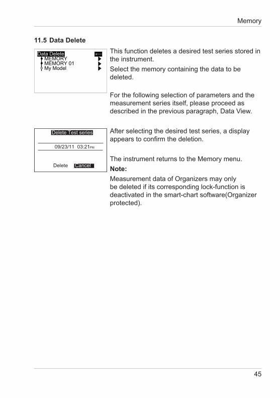
11.5 Data DeleteThis function deletes a desired test series stored in the instrument.Select the memory containing the data to be deleted. For the following selection of parameters and the measurement series itself, please proceed as describedinthepreviousparagraph,DataView.
After selecting the desired test series, a display appearstoconfirmthedeletion.
The instrument returns to the Memory menu.Note:MeasurementdataofOrganizersmayonlybe deleted if its corresponding lock-function is deactivatedinthesmart-chartsoftware(Organizerprotected).
Memory
09/23/11 03:21
Delete
PM
Delete Test series
Cancel
46
Setup
*
12. SetupIntheSetupmenuyoufindfunctionstoadjustthefollowing general settings of the instrument:
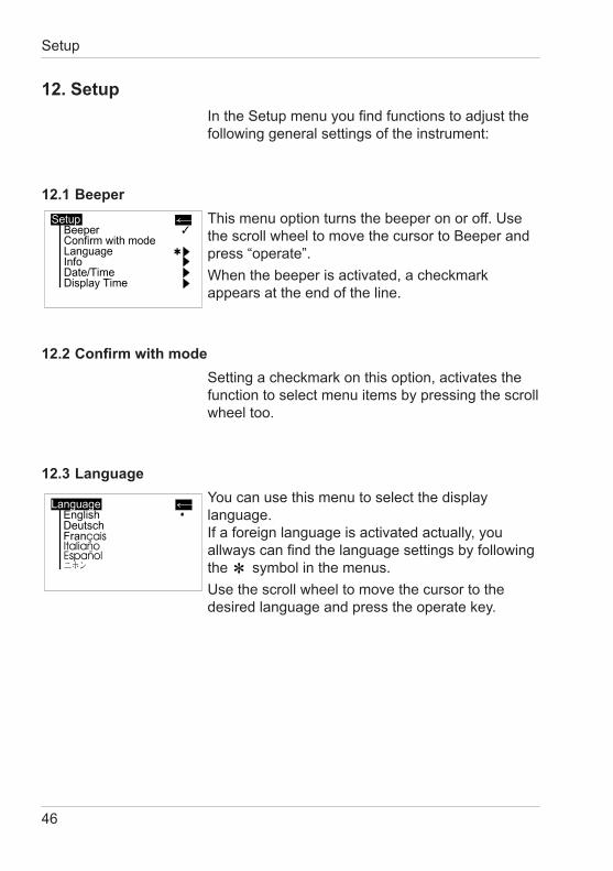
12.1 BeeperThis menu option turns the beeper on or off. Use the scroll wheel to move the cursor to Beeper and press“operate”.When the beeper is activated, a check mark appears at the end of the line.
12.2ConfirmwithmodeSetting a checkmark on this option, activates the function to select menu items by pressing the scroll wheel too.
12.3 LanguageYou can use this menu to select the display language. Ifaforeignlanguageisactivatedactually,youallwayscanfindthelanguagesettingsbyfollowingthe symbol in the menus.Use the scroll wheel to move the cursor to the desired language and press the operate key.
47
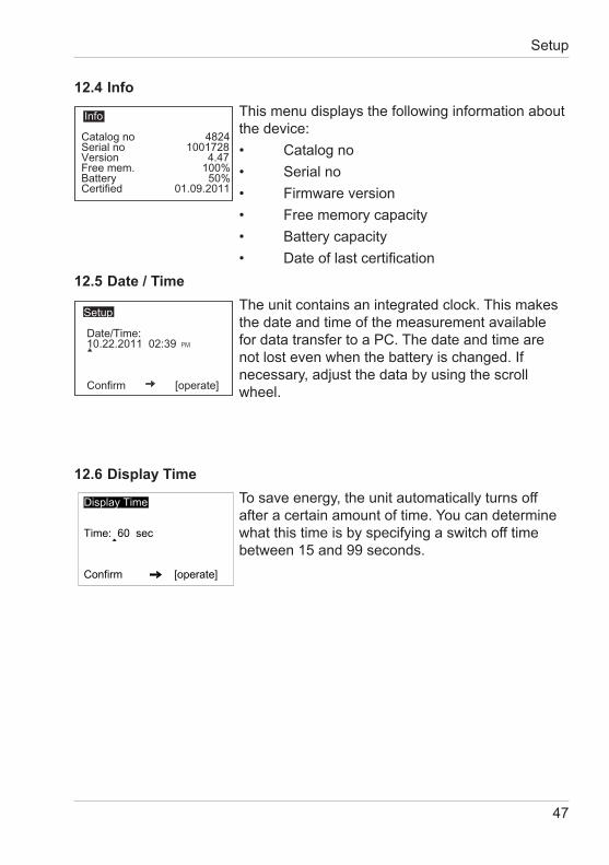
12.5 Date / TimeThe unit contains an integrated clock. This makes the date and time of the measurement available for data transfer to a PC. The date and time are notlostevenwhenthebatteryischanged.Ifnecessary, adjust the data by using the scroll wheel.
12.6 Display Time To save energy, the unit automatically turns off after a certain amount of time. You can determine what this time is by specifying a switch off time between 15 and 99 seconds.
12.4 InfoThis menu displays the following information about the device:• Catalogno• Serialno• Firmwareversion• Freememorycapacity• Batterycapacity• Dateoflastcertification
Setup
Catalog no 4824Serial no 1001728Version 4.47Free mem. 100%Battery 50%Certified 01.09.2011
Info
Date/Time:10.22.2011 02:39
Confirm [operate]
Setup
PM
48
Interface
13. Interface
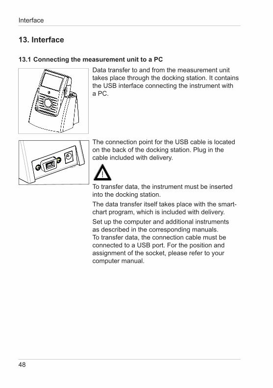
13.1 Connecting the measurement unit to a PCData transfer to and from the measurement unit takesplacethroughthedockingstation.Itcontainsthe USB interface connecting the instrument with a PC.
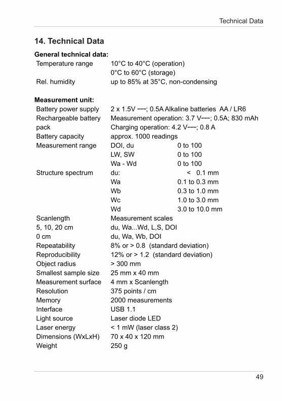
The connection point for the USB cable is located on the back of the docking station. Plug in the cable included with delivery.
To transfer data, the instrument must be inserted into the docking station. The data transfer itself takes place with the smart-chart program, which is included with delivery.Set up the computer and additional instruments as described in the corresponding manuals. To transfer data, the connection cable must be connected to a USB port. For the position and assignment of the socket, please refer to your computer manual.
49
Technical Data
14. Technical DataGeneral technical data: Temperature range 10°C to 40°C (operation) 0°C to 60°C (storage) Rel. humidity up to 85% at 35°C, non-condensing
Measurement unit:Batterypowersupply 2x1.5V ; 0.5A Alkaline batteries AA / LR6Rechargeablebattery Measurementoperation:3.7V ; 0.5A; 830 mAhpack Chargingoperation:4.2V ; 0.8 A Battery capacity approx. 1000 readingsMeasurementrange DOI,du 0to100 LW, SW 0 to 100 Wa - Wd 0 to 100 Structure spectrum du: < 0.1 mm Wa 0.1 to 0.3 mm Wb 0.3 to 1.0 mm Wc 1.0 to 3.0 mm Wd 3.0 to 10.0 mm Scanlength Measurement scales5,10,20cm du,Wa...Wd,L,S,DOI0cm du,Wa,Wb,DOI Repeatability 8% or > 0.8 (standard deviation) Reproducibility 12% or > 1.2 (standard deviation)Objectradius >300mm Smallest sample size 25 mm x 40 mm Measurement surface 4 mm x Scanlength Resolution 375 points / cm Memory 2000 measurementsInterface USB1.1 Light source Laser diode LED Laser energy < 1 mW (laser class 2) Dimensions (WxLxH) 70 x 40 x 120 mm Weight 250 g
50
Technical Data
Docking station:
Powersupply 5V ; 2.5 A Dimensions (WxLxH) 100x100x85mm Weight 315 g
External power supply:
Powersupply Input:100-240V;50/60Hz;800mA Output:5V;2.5A Dimensions (WxLxH) 95x55x35mm Weight 320 g
51
Infoanderrormessages
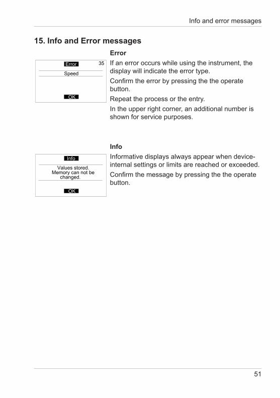
15. Info and Error messagesErrorIfanerroroccurswhileusingtheinstrument,thedisplay will indicate the error type.Confirmtheerrorbypressingthetheoperatebutton.Repeat the process or the entry.Intheupperrightcorner,anadditionalnumberisshown for service purposes.
InfoInformativedisplaysalwaysappearwhendevice-internal settings or limits are reached or exceeded.Confirmthemessagebypressingthetheoperatebutton.
52
Infoanderrormessages
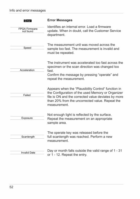
Identifiesaninternalerror.Loadafirmwareupdate. When in doubt, call the Customer Service department.
The measurement unit was moved across the sample too fast. The measurement is invalid and must be repeated.
The instrument was accelerated too fast across the specimen or the scan direction was changed too fast. Confirmthemessagebypressing“operate”andrepeat the measurement.
Appears when the “Plausibility Control“ function in theConfigurationoftheusedMemoryorOrganizerfileisONandthecorrectedvaluedeviatesbymorethan 20% from the uncorrected value. Repeat the measurement.
Notenoughlightisreflectedbythesurface.Repeat the measurement on an appropriate sample area.
The operate key was released before the full scanlength was reached. Perform a new measurement.
Day or month falls outside the valid range of 1 - 31 or 1 - 12. Repeat the entry.
Error Messages
53
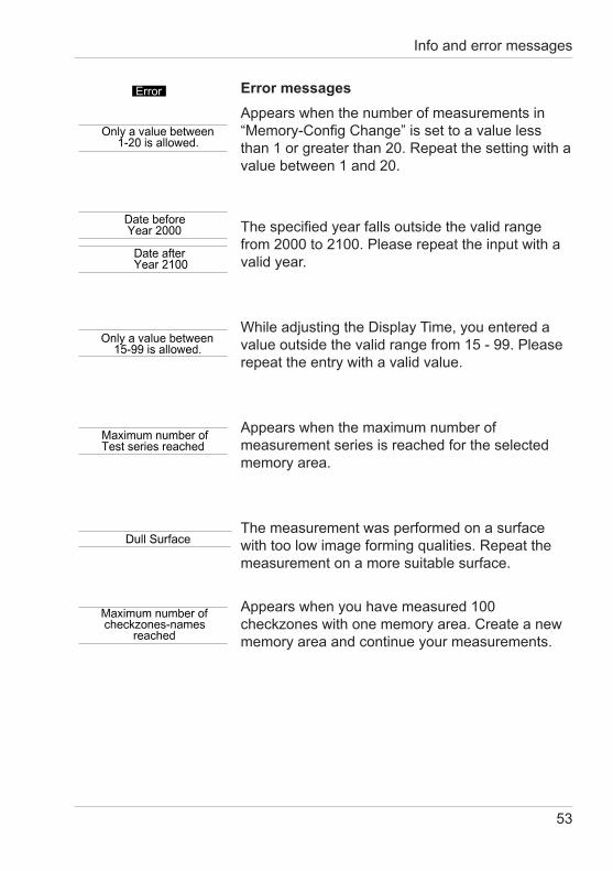
Appears when the number of measurements in “Memory-ConfigChange”issettoavaluelessthan 1 or greater than 20. Repeat the setting with a value between 1 and 20.
Thespecifiedyearfallsoutsidethevalidrangefrom 2000 to 2100. Please repeat the input with a valid year.
While adjusting the Display Time, you entered a value outside the valid range from 15 - 99. Please repeat the entry with a valid value.
Appears when the maximum number of measurement series is reached for the selected memory area.
The measurement was performed on a surface with too low image forming qualities. Repeat the measurement on a more suitable surface.
Appears when you have measured 100 checkzones with one memory area. Create a new memory area and continue your measurements.
Error messages
Infoanderrormessages
54
Infoanderrormessages
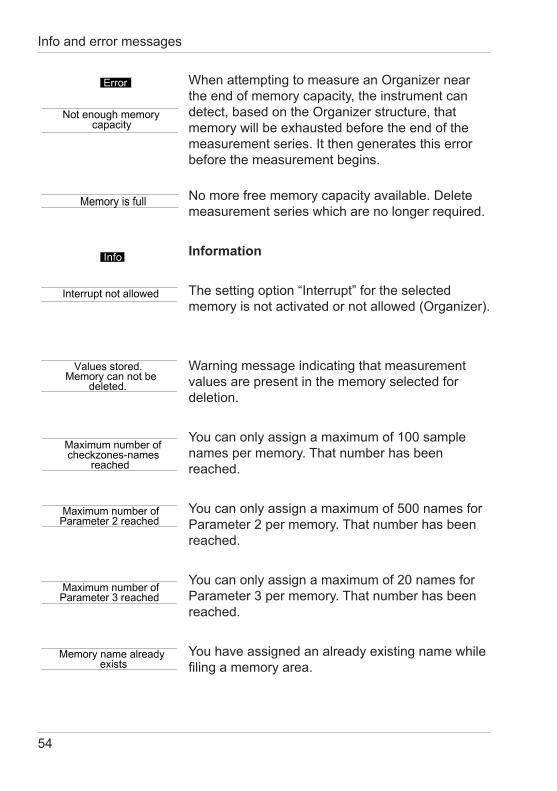
WhenattemptingtomeasureanOrganizernearthe end of memory capacity, the instrument can detect,basedontheOrganizerstructure,thatmemory will be exhausted before the end of the measurementseries.Itthengeneratesthiserrorbefore the measurement begins.
No more free memory capacity available. Delete measurement series which are no longer required.
Information
Thesettingoption“Interrupt”fortheselectedmemoryisnotactivatedornotallowed(Organizer).
Warning message indicating that measurement values are present in the memory selected for deletion.
You can only assign a maximum of 100 sample names per memory. That number has been reached.
You can only assign a maximum of 500 names for Parameter 2 per memory. That number has been reached.
You can only assign a maximum of 20 names for Parameter 3 per memory. That number has been reached.
You have assigned an already existing name while filingamemoryarea.
55
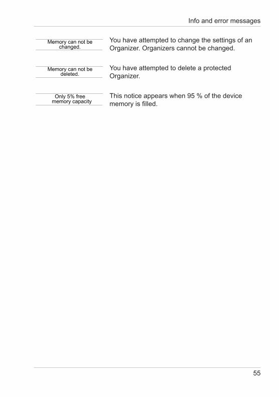
You have attempted to change the settings of an Organizer.Organizerscannotbechanged.
You have attempted to delete a protected Organizer.
This notice appears when 95 % of the device memoryisfilled.
Infoanderrormessages
56
16. Cleaning and maintenance
• Beforecleanig,theinstrumentandaccessoriesmust be disconnected from the power supply as described in the safety instructions.
• Donotinsertanyobjectsintothemeasurementaperture for cleaning. The instrument could get damaged - affecting a proper and safe operation.
• Do not use any acetone! The instrument housing is resistant to a number of solvents, but cannot be guaranteed to withstand all chemicals. You should therefore use a soft, moist cloth for cleaning. For cleaning excessive dirt, use propanol.
• Acleaningmattocleantheunit’swheelsissituated on top of the reference tile’s cover. Therefore, roll the wheels several times over the mat and then over a cleen sheet of paper. Dirt will stick to the mat and can be removed with clear water.
Cleaning and maintenance
57
Cleaning the test tile•Donotuseanyacetone!
The accuracy of the measurement can be significantlyimpactedbyusingdirtyordamagedstandards.Since the surfaces of the standards are highly sensitive, cleaning must be undertaken with great care.To clean standards, use a new lint-free cloth, dust-free lens paper or an optical cloth.Apply only slight pressure as you clean and make certain there are no large particles stuck in the cloth that could damage the surface. Fordirtthatisdifficulttoremove,useanopticalcloth dipped in liquid. Then wipe the surface with a dry optical cloth.Exact calibration is not possible unless the standardisinperfectcondition.Iftheconditionof the standard seems doubtful because of its appearance or measurement errors, we will be happy to check it for you.
Cleaning and maintenance
58
17.ServiceandCertification
ServiceBesides the repair of your instrument we offer the following additional services:First diagnosis on the telephone or by e-mailCall us or send us an e-mail and we will try to solve yourproblem.Ifthisisnotsuccessful,pleasesendus the instrument for repair.Preventive maintenance, calibration, and recertificationFor precautionary reasons we recommend regular preventive maintenance. We carry out this preventive maintenance automatically when you send us your instrument for maintenance andrecertification.Wecleantheoptics,checkall functions, test and, if required, adjust the measured values by using reference standards. Youwillreceiveacertificate,whichincludestheretraceability to international standards.LoanersDuring the period of repair we furnish you with a loaner on request and availability.Maintenance agreementIncaseyouwanttomakesurethatthenecessarymaintenance is being done on a regular basis and on time, we recommend a maintenance agreement.Extended warranty contractsFurthermore, you can request an extended warranty contract for additional 12 months.Ordering information:SE-4824 extended warranty
ServiceandCertification
59
Service Centers for BYK-Gardner products
GermanyBYK-Gardner GmbH Lausitzer Strasse 8 82538 Geretsried GermanyPhone:+49-8171-3493-0 Fax: +49-8171-3493-166USABYK-Gardner USA 9104 Guilford Road Columbia, MD 21046 USAPhone:+1-301-483-6500 Fax: +1-301-483-6555ChinaBYK-GardnerShanghaiOffice3/F, Building 22 No. 140 Tian Lin Road Xuhui District Shanghai 200233 P.R. ChinaPhone.: +86(021)3367-6331 Fax: +86(021)3367-6332BrazilBYK-Gardner Latin America RuaItaporanga,340 Bairro Paraíso -Santo André-SP CEP 09190-640 BrazilPhone.: +55-11-2147-1199 Fax: +55-11-2147-1168
Service Centers for BYK-Gardner products
60
18. Copyright
This instruction manual is an important part of this instrument. It contains es-sential information about setting up, placing in service and use. If you pass the device on to another user, please ensure that the instruction manual is included with the instrument. The manual must be studied carefully before working with the equipment. Please contact your regional service office if you have any questions or require additional information about the device.
The technology and fittings are based on state-of-the art optic and electro-nic technology. New developments and innovations are constantly being integrated into the equipment. Thus, the diagrams, dimensions, and techni-cal data used in this manual may have changed as a result of adapting the device to new information and improvements.
© Copyright 2011 BYK-Gardner GmbHAll rights reserved
No portion of the software, documentation or other accompanying materials may be translated, modified, reproduced, copied or otherwise duplicated (with the exception of a backup copy), or distributed to a third party, without prior written authorization from BYK-Gardner GmbH. In any case, this re-quires the prior written consent of BYK-Gardner.
BYK-Gardner GmbH offers no guarantee that the software will function wit-hout error or that the functions incorporated therein can be executed in all applications and combinations selected by you.
No liability other than as provided by law is assumed for direct or indirect damage sustained in association with the use of the instrument, the softwa-re or documentation.
BYK-Gardner GmbH reserves the right to update the software and written documentation without prior notice.
Copyright

262 022 432 E 1111