Embed Size (px)
Citation preview

BM 26 Technical Datasheet
Bypass Level Indicator
• Most compact bypass level indicator on the market• Robust, stainless steel design• Permanent, IP68 local indication without power supply
TD_BM26_EN_071112.book Page 1 Monday, November 12, 2007 11:19 AM

BM 26 nnnnnnnnnnnnnnnnnnnnnnnnnnnnnnnnnnnnnnnnnnnnnnnnnnnnnnnnnnnnnnn
www.krohne.com 2
The BM 26BM 26BM 26BM 26 is a simple, rugged instrument designed to indicate level or interface. It indicates level using a float magnetically coupled to an index or a column of rotating flaps. It is ideal for aggressive media stored in tanks when the PTFE lining option is used.For liquids with densities less than 0.5 kg/l / 31 lb/ft³, pressures more than 120 bar / 1740 psig and temperatures higher than 300°C / 570 °F, we recommend our BW 25 displacer-type level indicator.
Highlights
• Stainless steel design (optional NACE conformity)
• Proven technology
• Temperature range: -200…+300°C /-325…+570°F
• Pressure range: -1…120 bar / -14.5…1740 psig
• Density: 0.5…3 kg/l / 31…187 lb/ft³
• Float material options: 316L, 316 Ti and Titanium
• Stainless steel scale with wide choice of markings: m/cm, ft/in, %, volume etc.
• Less risk of leakage than a sight glass - little or no maintenance needed
• Easy to install
• Ideal for tanks with obstructed environments
• Optional indication of interface
• Optional approvals for EEx i or EEx d applications
Industries
• Chemical and Petrochemical
• Oil and Gas
• Power
Applications
• Boilers
• Condensators
• Hydrocarbons and Separators
• Liquid gas
• Process and storage tanks
• Steam cracking
1 Option: level transducer2 IP 68 level indicator (pyrex tube with an index or a column of ro-
tating flaps)3 Stainless steel bypass chamber (316 L or 316 Ti), with optional
PTFE lining for acids4 Option: drain with plug or flange connection5 Option: limit switches6 Versions: side or inline process connections (with loose or
welding neck flanges)7 Option: vent with plug or flange connection
The proven mechanical-based solution for level indication
TD_BM26_EN_071112.book Page 2 Monday, November 12, 2007 11:19 AM

nnnnnnnnnnnnnnnnnnnnnnnnnnnnnnnnnnnnnnnnnnnnnnnnnnnnnnnnnnnnnnn BM 26
www.krohne.com 3
An example of a typical industrial application
Level indication on large tanks often involves a complex arrangement of devices set up to indicate level and provide an analogue output.
1. Small bypass or displacer-type level indicators in a series arrangement
2. Sight glass3. Bypass chamber with analogue output4. Tank
KROHNE's all-in-one equivalent using the BM 26
The BM 26 is a bypass level indicator that provides you with an all-in-one alternative. You only need one BM 26 to read level locally or remotely, integrate the instrument into a network and receive alarms at critical points (tank full, sunk float etc).
1. Limit switches in high-high, high, low, low-low and sink detection positions. The user can adjust these positions on-site.
2. Bypass level indicator (magnetic)3. Level transducer with analogue or network out-
put4. Tank
1
1
1
1
2 3
4
4
3
2
1
1
1
1
1
A simpler and cheaper alternative for your application
TD_BM26_EN_071112.book Page 3 Monday, November 12, 2007 11:19 AM

BM 26 nnnnnnnnnnnnnnnnnnnnnnnnnnnnnnnnnnnnnnnnnnnnnnnnnnnnnnnnnnnnnnn
www.krohne.com 4
BM 26 A BM 26 PTFE-lined
InputDevice Magnetic level indicator
Function Float magnetically coupled to a mechanical level indicator
Parameter Level, interface, or volume
Max. measuring range 0.3…6 m / 1…20 ft 1 0.3…5.5 m / 1…18 ft 1
OutputOutput signal see "Technical data: optional level transducer" (if option fitted)
Error signal see "Technical data: optional level transducer" (if option fitted)
AccuracyRepeatability ±10 mm / ±0.4“
Accuracy ±10 mm / ±0.4"
Process conditions Ambient temperature -40…+85°C / -40…+185°F;
EEx i: see supplementary operating instructions or approval certificates
-20…+85°C / -4…+185°F
Storage temperature -40…+85°C / -40…+185°F
Process temperature -40…+200°C / -40…+390°F;EEx i: see supplementary operating instructions or approval certificates 2
-20…+200°C / -40…+390°F
Thermal resistance 100°C/min / 210°F/min
Operating pressure -1…40 bar / -14.5…580 psig 3 0…10 bar / 0…145 psig 3
Product density 0.5…3 kg/l / 31…187 lb/ft³
Viscosity ≤5000 mPas / ≤3.360 lb/fts
Protection category IP 68 equivalent to NEMA 6-6X
Technical data: general information
TD_BM26_EN_071112.book Page 4 Monday, November 12, 2007 11:19 AM

nnnnnnnnnnnnnnnnnnnnnnnnnnnnnnnnnnnnnnnnnnnnnnnnnnnnnnnnnnnnnnn BM 26
www.krohne.com 5
BM 26 A BM 26 PTFE-lined
MaterialChamber Stainless steel (1.4404 / 316L);
Stainless steel (1.4571 / 316Ti)Stainless steel (1.4404 / 316L)with PTFE lining
Float Stainless steel (1.4404 / 316L);Stainless steel (1.4571 / 316Ti); Titanium
Glass; PTFE
Indicator tube Pyrex glass
Scale Stainless steel
Process fitting Stainless steel (1.4404 / 316L);Stainless steel (1.4571/ 316Ti)
Stainless steel (1.4404 / 316L)with PTFE lining
Gaskets Klingerit; PTFE PTFE
Heater casing Stainless steel (1.4404 / 316L) 4 -
Insulation Glass fibre wool 5 -
Magnifier glass Plexitherm glass 6 -
Process connectionsLoose flange DN15…50 (PN40) 1 -
Welding Neck flange DN15…50 (PN40);½"…2" (150 lb / 300 lb) 1
DN25…50 (PN10);1"…2" (150 lb) 1
Drain and vent connectionsThread G or NPT 3/8; G or NPT 1/2; NPT 3/4 NPT 1/2
Flange DN15, 25 PN40; 1/2…1" (150 lb/300 lb) DN15…25 (PN16); 1/2"…1" (150 lb)
DisplayDisplay options Indicator column - magnetically-coupled floating index
Indicator column - magnetically coupled, yellow/black rotating flaps
Scale markings: m+cm; ft+in; or % 7
Design codesConformity to pressure equipment directives
PED 97/23/EC
Pressure vesselconstruction code
CODAP® 2005
Options NACE MR0175 / ISO 15156 -
TD_BM26_EN_071112.book Page 5 Monday, November 12, 2007 11:19 AM

BM 26 nnnnnnnnnnnnnnnnnnnnnnnnnnnnnnnnnnnnnnnnnnnnnnnnnnnnnnnnnnnnnnn
www.krohne.com 6
BM 26 A BM 26 PTFE-lined
ApprovalsATEX ATEX II 1/2 G EEx d IIC T3…T6;
ATEX II 1/2 G EEx d ia IIC T3…T6;ATEX II 1 G EEx ia IIC T3…T6
Variants, options and accessoriesVariants C: two side connections C: two side connections
D: two inline connections -
E: top side connection and bottom inline connection
-
F: top inline connection and bottom side connection
-
Sub-variants Standard
AG / long connection AG: low temperature(min -40°C / -40°F)
-
B: With heating/cooling system 8 -
TR: very low-temperature (min.-200°C / -330°F)
-
IC/TR: very low-temperature, with insulation jacket(min.-200°C / -330°F )
-
HR: high-temperature(+200…+300°C / +390…570°F)
-
IC/HR: high-temperature, with insulation jacket(+200…+300°C / +390…570°F)
-
Options Level transducer
Limit switches
Accessories Insulation jacket 9 -
1 other sizes on request2 Optional non-Ex -200…+300°C / -325…+570°F3 subject to process connection used and flange temperature; information on higher pressure levels available on request 4 for the heating/cooling system sub-variant (B)5 for the insulated high-temperature sub-variant (IC/HR) or the insulated very low-temperature sub-variant (IC/TR)6 for the low temperature sub-variant (AG)7 volume units on request8 2 DN15 connections - or optionally tubes for Ermeto 12 connectors - are provided for the heat transfer fluid9 for indicators with long process connections
TD_BM26_EN_071112.book Page 6 Monday, November 12, 2007 11:19 AM

nnnnnnnnnnnnnnnnnnnnnnnnnnnnnnnnnnnnnnnnnnnnnnnnnnnnnnnnnnnnnnn BM 26
www.krohne.com 7
PR 5343B4...20 mA output
PR 5350BPROFIBUS PA® or FF
outputPR 5335B
4...20 mA/HART® output
InputDevice Level transducer (column of reed resistors conected to a transmitter module)
mounted on the side of the BM 26 bypass chamber
Function Reed-chain magnetically actuated by float in BM 26 bypass chamber
Parameter Level
Max. measuring range 0.3…6 m / 1…20 ft
OutputOutput signal 4…20 mA PROFIBUS® PA protocol
Profile A&B, ver. 3.0 (EN 50710 vol.2) or FOUNDATION™ Fieldbus protocol
4…20 mA/HART
Error signal High: 23 mA; Low: 3.5 mA - High: 23 mA; Low: 3.5 mA
AccuracyRepeatability ±10 mm / ±0.4“
Accuracy ±10 mm / ±0.4"
Process conditions Ambient temperature -40…+85°C / -40…+185°F;
EEx i: see supplementary operating instructions or approval certificates
Process temperature -40…+200°C / -40…+390°F;EEx i: see supplementary operating instructions or approval certificates 1
Protection category IP 65 equivalent to NEMA 4-4X
Electromagnetic compatibility (EMC)
EN 61326
89/336/EEC (EMC Directive)
2006/95/EC (Low Voltage Directive)
MaterialTransmitter module housing Aluminium
Probe Stainless steel (1.4404 / 316L)
Bracket Aluminium (stainless steel for high-temperature versions)
Clamp Stainless steel
Electrical connectionsInstrument terminal - non Ex 8…35 VDC 2 9….32 VDC 8…35 VDC 2
Instrument terminal - EEx 8…30 VDC 2 9…30 VDC 8…30 VDC 2
Maximum safety values 3 See supplementary operating instructions or approval certificates
Cable entry M20 x 1.5, M25 x 1.5 or NPT¾ 4
Technical data: optional level transducer
TD_BM26_EN_071112.book Page 7 Monday, November 12, 2007 11:19 AM

BM 26 nnnnnnnnnnnnnnnnnnnnnnnnnnnnnnnnnnnnnnnnnnnnnnnnnnnnnnnnnnnnnnn
www.krohne.com 8
PR 5343B4...20 mA output
PR 5350BPROFIBUS PA® or FF
outputPR 5335B
4...20 mA/HART® output
ApprovalsATEX ATEX II 1/2 G EEx d IIC T3…T6 or ATEX II 1/2 G EEx d ia IIC T3…T6;
ATEX II 1 G EEx ia IIC T3…T6
1 for HR versions: +300°C / 570°F2 min./max. value for an output of 23 mA at the terminal3 for EEx i applications4 Cable fitting is not supplied: only use fittings and other components that are EEx-certified, if EEx i or EEx d approval is chosen
TD_BM26_EN_071112.book Page 8 Monday, November 12, 2007 11:19 AM

nnnnnnnnnnnnnnnnnnnnnnnnnnnnnnnnnnnnnnnnnnnnnnnnnnnnnnnnnnnnnnn BM 26
www.krohne.com 9
Standard (Non-Ex) switches
Type code
MS20STD/LC/PC/NN
/BT
MS15STD/LC/PC/NO
/BT
MS15STD/LC/AL/NN
/HT
MS15STD/LC/AL/NO/
HT
MS15STD/HC/PC/NN
/BT
MS15STD/HC/AL/NN
/HT
VersionLow price, standard NAMUR
High-temperature
NAMUR, high-temperature
High-power cut-out
High-power cut-out, high temperature
InputDevice Level switch mounted on the side of the BM 26 bypass chamber
Function Reed switch that is magnetically actuated by float in BM 26 bypass chamber
Parameter Level detection
Switching capacity
30 VA; 0.5 A;230 VAC
1 20 VA; 1.5 A;250 VAC
2 3…100VA1.5 A;250 VAC
3…100VA1.5 A;250 VAC
AccuracyHysteresis Not applicable
Process conditions Ambient temperature
-20…+120°C / -4…+250°F 3
Process temperature
-40…+250°C /-40…+480°F
-40…+250°C /-40…+480°F
-40…+300°C /-40…+570°F
-40…+300°C /-40…+570°F
-40…+250°C /-40…+480°F
-40…+300°C /-40…+570°F
Protection category
IP 65 equivalent to NEMA 4-4X
MaterialSwitch housing Polycarbonate Polycarbonate Aluminium Aluminium Polycarbonate Aluminium
Bracket Stainless steel
Clamp Stainless steel
Electrical connectionsCable entry PG 9 PG 13.5 M20 x 1.5 4 M20 x 1.5 4 PG 13.5 M20 x 1.5 5
1 according to NAMUR 19234. Connect to a NAMUR amplifier.2 according to NAMUR 19234. Connect to a NAMUR amplifier.3 specify temperature if an insulation jacket is used4 Optional: M25 x 1.5 or NPT¾. Cable fitting not supplied.5 Optional: M25 x 1.5 or NPT¾. Cable fitting not supplied.
Technical data: optional level switches
TD_BM26_EN_071112.book Page 9 Monday, November 12, 2007 11:19 AM

BM 26 nnnnnnnnnnnnnnnnnnnnnnnnnnnnnnnnnnnnnnnnnnnnnnnnnnnnnnnnnnnnnnn
www.krohne.com 10
Exi-approved switches
Type codeMS20
EXI/LC/PC/NN/BTMS15
EXI/LC/PC/NO/BTMS15
EXI/LC/AL/NN/HTMS15
EXI/LC/AL/NO/HT
Version low price, standard NAMUR high-temperatureNAMUR, high-temperature
InputDevice Level switch mounted on the side of the BM 26 bypass chamber
Function Reed switch that is magnetically actuated by float in BM 26 bypass chamber
Parameter Level detection
Switching capacity
0.5 A 1 2 1.5 A 1 2
AccuracyHysteresis Not applicable
Process conditions Ambient temperature
3
Process temperature
3 3 3 3
Protection category
IP 65 equivalent to NEMA 4-4X
MaterialSwitch housing Polycarbonate Polycarbonate Aluminium Aluminium
Bracket Stainless steel
Clamp Stainless steel
Electrical connectionsPower supply characteristics
See supplementary operating instructions or approval certificates.
Cable entry PG 9 PG 13.5 M20 x 1.5 4 M20 x 1.5 4
ApprovalsATEX ATEX II 1 G EEx ia IIC T3…T6
1 Only connect to a certified intrinsically-safe power supply. Safety values: see supplementary operating instructions or approval certi-ficates.
2 according to NAMUR 19234. Connect a NAMUR amplifier.3 Dependant on temperature class: see supplementary operating instructions or approval certificates.4 Optional: M25 x 1.5 or NPT¾. Cable fitting not supplied.
TD_BM26_EN_071112.book Page 10 Monday, November 12, 2007 11:19 AM

nnnnnnnnnnnnnnnnnnnnnnnnnnnnnnnnnnnnnnnnnnnnnnnnnnnnnnnnnnnnnnn BM 26
www.krohne.com 11
Exd-approved switches
Type codeMS15
EXD/LC/AL/NN/HTMS15
EXD/LC/AL/NO/HTMS15
EXD/HC/AL/NN/HT
Version high-temperature NAMUR, high-temperaturehigh-power cut-out, high-
temperature
InputDevice Level switch mounted on the side of the BM 26 bypass chamber
Function Reed switch that is magnetically actuated by float in BM 26 bypass chamber
Parameter Level detection
Switching capacity
20 VA; 1.5 A; 250 VAC 1 1.5 A 2
AccuracyHysteresis Not applicable
Process conditions Ambient temperature
3
Process temperature
4 4 4
Protection category
IP 65 equivalent to NEMA 4-4X
MaterialSwitch housing Aluminium Aluminium Aluminium
Bracket Stainless steel
Clamp Stainless steel
Electrical connectionsCable entry M20 x 1.5 5 M20 x 1.5 5 M20 x 1.5 5
ApprovalsATEX ATEX II 1/2 G EEx d ia IIC T3…T6
1 according to NAMUR 19234. Connect a NAMUR amplifier.2 Only connect to a certified intrinsically-safe power supply. Safety values: see supplementary operating instructions or approval certi-
ficates.3 Dependant on temperature class: see supplementary operating instructions or approval certificates. 4 Dependant on temperature class: see supplementary operating instructions or approval certificates.5 Optional: M25 x 1.5 or NPT¾. Cable fitting not supplied.
TD_BM26_EN_071112.book Page 11 Monday, November 12, 2007 11:19 AM

BM 26 nnnnnnnnnnnnnnnnnnnnnnnnnnnnnnnnnnnnnnnnnnnnnnnnnnnnnnnnnnnnnnn
www.krohne.com 12
Variant C: two side process connectionsVariant C: two side process connectionsVariant C: two side process connectionsVariant C: two side process connections
Standard, low-temperature (AG), and high-temperature (HR) sub-variantsStandard, low-temperature (AG), and high-temperature (HR) sub-variantsStandard, low-temperature (AG), and high-temperature (HR) sub-variantsStandard, low-temperature (AG), and high-temperature (HR) sub-variants
1 Optional drain or vent with flange connection2 Optional drain or vent with G or NPT plug3 Optional MS20 limit switch4 Optional MS15 limit switch for low-temperature applications5 Optional MS15 limit switch for high-temperature and Ex d applications6 Optional level transducer7 Low temperature sub-variant (AG): Indicating tube with plexitherm glass cover (prevents condenstion forming on indicating tube)
High-temperature sub-variant (HR): High-temperature indicating tube with floating index
Dimensions and Weights
TD_BM26_EN_071112.book Page 12 Monday, November 12, 2007 11:19 AM

nnnnnnnnnnnnnnnnnnnnnnnnnnnnnnnnnnnnnnnnnnnnnnnnnnnnnnnnnnnnnnn BM 26
www.krohne.com 13
Dimensions in mm
Dimensions in inches
Weight in kg and lbs
Dimensions [mm]
a X b L M c d e f g h p r s t u
Sub-variants:StandardAGHR
300 1 200 300 … 6000
2 72 3
115 4
375 116 116 150 … 170 5
146 6
100 7
98 8
Ø72 x 2.3
Ø130
1 Standard connections: according to process connection size. See the "Process connection dimension X" table at the end of this section. Long connections: 165 mm
2 this is the measuring range of the indicator column. It is equal to the dimension L.3 100 mm for low-temperature sub-variant4 165 mm for long connections5 with optional level transducer6 with optional MS15 limit switch for high-temperature and Ex d applications7 with optional MS15 limit switch for low-temperature applications8 with optional MS20 limit switch
Dimensions [inches]
a X b L M c d e f g h p r s t u
Sub-variants:StandardAGHR
12.0 1 7.9 12 … 236
2 2.8 3
4.5 4
14.8 4.6 4.6 6 … 6.7 5
5.7 6
4.0 7
3.9 8
Ø2.8 x 0.09
Ø5.1
1 Standard connections: according to process connection size. See the "Process connection dimension X" table at the end of this section. Long connections: 6.5"
2 this is the measuring range of the indicator column. It is equal to the dimension L.3 3.9" for low-temperature sub-variant4 6.5" for long connections5 with optional level transducer6 with optional MS15 limit switch for high-temperature and Ex d applications7 with optional MS15 limit switch for low-temperature applications8 with optional MS20 limit switch
Weightwhen L=1000 mm
Weightwhen L=40 inches
Weight for every additional 100 mm
Weight for every additional 4 inches
[kg] [lbs] [kg] [lbs]
Bypass chamber 14.5 32.0 0.5 1.1
Level transducer 2.3 5.1 0.1 0.2
MS15 BT limit switch 1 0.13 0.3
MS15 HT limit switch 2 1.2 2.6
MS20 limit switch 0.085 0.2
1 for low-temperature applications2 for high-temperature applications
TD_BM26_EN_071112.book Page 13 Monday, November 12, 2007 11:19 AM

BM 26 nnnnnnnnnnnnnnnnnnnnnnnnnnnnnnnnnnnnnnnnnnnnnnnnnnnnnnnnnnnnnnn
www.krohne.com 14
Heating/cooling system sub-variant (B)Heating/cooling system sub-variant (B)Heating/cooling system sub-variant (B)Heating/cooling system sub-variant (B)
1 Optional drain or vent with flange connection2 Optional drain or vent with G or NPT plug3 Optional MS20 limit switch4 Optional MS15 limit switch for low-temperature applications5 Optional MS15 limit switch for high-temperature and Ex d applications6 Heating system inlet/outlet. Options: DN15 PN40 flange connection or tube for Ermeto 127 Optional level transducer
TD_BM26_EN_071112.book Page 14 Monday, November 12, 2007 11:19 AM

nnnnnnnnnnnnnnnnnnnnnnnnnnnnnnnnnnnnnnnnnnnnnnnnnnnnnnnnnnnnnnn BM 26
www.krohne.com 15
Dimensions in mm
Dimensions in inches
Weight in kg and lbs
Dimensions [mm]
a X b L M c d e f g h j m p r s t u
Sub-variant:B
300 165 200 300 … 6000
1 76 165 375 116 116 150 … 170 2
L+304
165 3
146 4
100 5
98 6
Ø72 x 2.3
Ø130
1 this is the measuring range of the indicator column. It is equal to the dimension L.2 with optional level transducer3 100 mm for optional tube for Ermoto 12 connection4 with optional MS15 limit switch for high-temperature and Ex d applications5 with optional MS15 limit switch for low-temperature applications6 with optional MS20 limit switch
Dimensions [inches]
a X b L M c d e f g h j m p r s t u
Sub-variant:B
12.0 6.5 7.9 12 … 236
1 3.0 6.5 14.8 4.6 4.6 6 … 6.7 2
L+12.0
6.5 3
5.7 4
4.0 5
3.9 6
Ø2.8 x 0.09
Ø5.1
1 this is the measuring range of the indicator column. It is equal to the dimension L2 with optional level transducer3 4.0" for optional tube for Ermoto 12 connection4 with optional MS15 limit switch for high-temperature and Ex d applications5 with optional MS15 limit switch for low-temperature applications6 with optional MS20 limit switch
Weightwhen L=1000 mm
Weightwhen L=40 inches
Weight for every additional 100 mm
Weight for every additional 4 inches
[kg] [lbs] [kg] [lbs]
Bypass chamber 14.5 32.0 0.5 1.1
Level transducer 2.3 5.1 0.1 0.2
MS15 BT limit switch 1 0.13 0.3
MS15 HT limit switch 2 1.2 2.6
MS20 limit switch 0.085 0.2
1 for low-temperature applications2 for high-temperature applications
TD_BM26_EN_071112.book Page 15 Monday, November 12, 2007 11:19 AM

BM 26 nnnnnnnnnnnnnnnnnnnnnnnnnnnnnnnnnnnnnnnnnnnnnnnnnnnnnnnnnnnnnnn
www.krohne.com 16
Insulated high-temperature (IC/HR) and insulated very low-temperature (IC/TR) sub-variants Insulated high-temperature (IC/HR) and insulated very low-temperature (IC/TR) sub-variants Insulated high-temperature (IC/HR) and insulated very low-temperature (IC/TR) sub-variants Insulated high-temperature (IC/HR) and insulated very low-temperature (IC/TR) sub-variants
1 Optional drain or vent with flange connection2 Optional drain or vent with G or NPT plug3 Optional MS20 limit switch4 Optional MS15 limit switch for low-temperature applications5 Optional MS15 limit switch for high-temperature and Ex d applications6 Optional level transducer7 Optional insulation jacket8 Insulated high-temperature sub-variant (IC/HR): high-temperature indicating tube with floating index
Insulated very low-temperature sub-variant (IC/HR): indicating tube with plexitherm glass cover (magnifies indicator and prevents condensation forming on the indicating tube)
TD_BM26_EN_071112.book Page 16 Monday, November 12, 2007 11:19 AM

nnnnnnnnnnnnnnnnnnnnnnnnnnnnnnnnnnnnnnnnnnnnnnnnnnnnnnnnnnnnnnn BM 26
www.krohne.com 17
Dimensions in mm
Dimensions in inches
Weight in kg and lbs
Dimensions [mm]
a X b L M c d e f g h p r s t u v
Sub-variants:IC/HRIC/TR
300 165 200 300 … 6000
1 100 2
165 375 116 116 150…170 3
146 4
100 5
98 6
Ø72 x 2.3
Ø130 Ø200
1 this is the measuring range of the indicator column. It is equal to the dimension L.2 for IC/HR sub-variant. IC/TR sub-variant: 116 mm.3 with optional level transducer4 with optional MS15 limit switch for high-temperature and Ex d applications5 with optional MS15 limit switch for low-temperature applications6 with optional MS20 limit switch
Dimensions [inches]
a X b L M c d e f g h p r s t u v
Sub-variants:IC/HRIC/TR
12.0 6.5 7.9 12 … 236
1 4.0 2
6.5 14.8 4.6 4.6 6 … 6.7 3
5.7 4
4.0 5
3.9 6
Ø2.8 x 0.09
Ø5.1 Ø7.9
1 this is the measuring range of the indicator column. It is equal to the dimension L.2 for IC/HR sub-variant. IC/TR sub-variant: 4.6". 3 with optional level transducer4 with optional MS15 limit switch for high-temperature and Ex d applications5 with optional MS15 limit switch for low-temperature applications6 with optional MS20 limit switch
Weightwhen L=1000 mm
Weightwhen L=40 inches
Weight for every additional 100 mm
Weight for every additional 4 inches
[kg] [lbs] [kg] [lbs]
Bypass chamber 14.5 32.0 0.5 1.1
Level transducer 2.3 5.1 0.1 0.2
MS15 BT limit switch 1 0.13 0.3
MS15 HT limit switch 2 1.2 2.6
MS20 limit switch 0.085 0.2
1 for low-temperature applications2 for high-temperature applications
TD_BM26_EN_071112.book Page 17 Monday, November 12, 2007 11:19 AM
BM 26 nnnnnnnnnnnnnnnnnnnnnnnnnnnnnnnnnnnnnnnnnnnnnnnnnnnnnnnnnnnnnnn
www.krohne.com 18
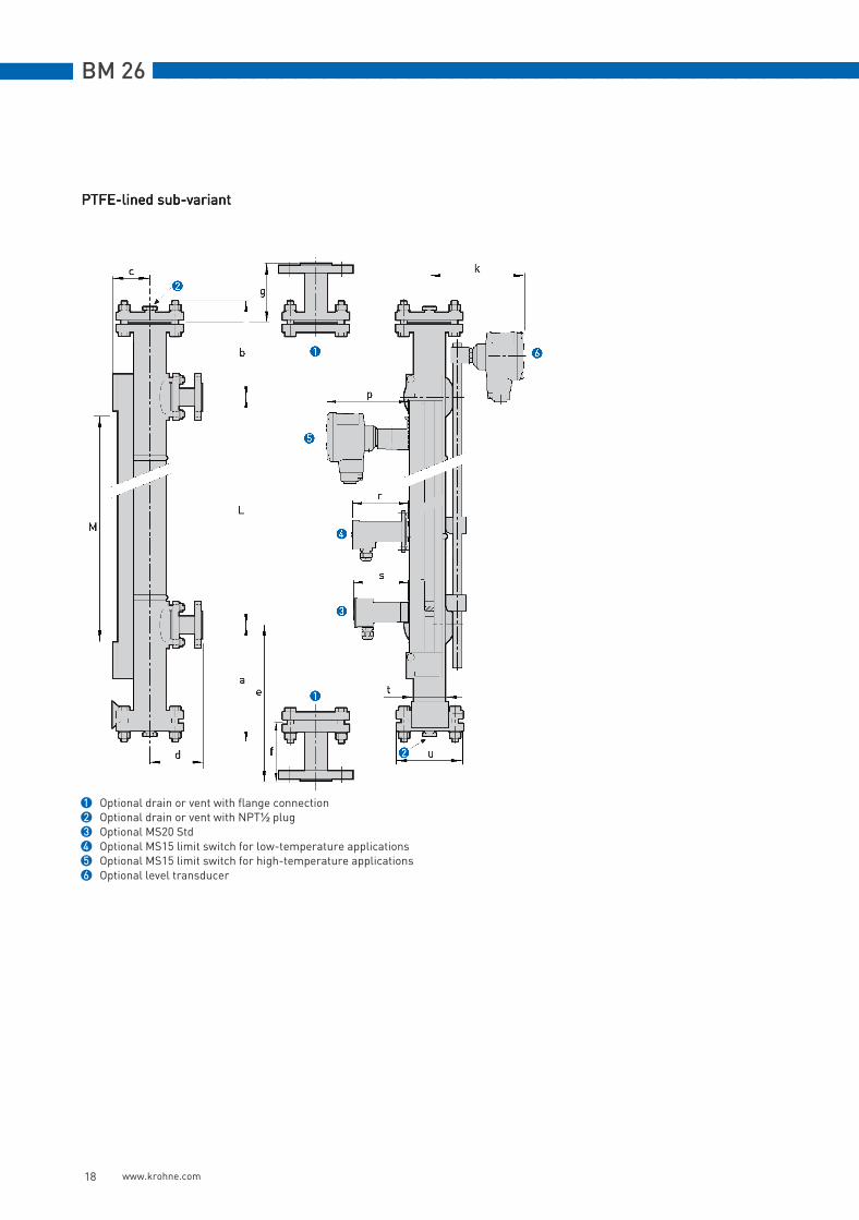
PTFE-lined sub-variantPTFE-lined sub-variantPTFE-lined sub-variantPTFE-lined sub-variant
1 Optional drain or vent with flange connection2 Optional drain or vent with NPT½ plug3 Optional MS20 Std4 Optional MS15 limit switch for low-temperature applications5 Optional MS15 limit switch for high-temperature applications6 Optional level transducer
TD_BM26_EN_071112.book Page 18 Monday, November 12, 2007 11:19 AM
nnnnnnnnnnnnnnnnnnnnnnnnnnnnnnnnnnnnnnnnnnnnnnnnnnnnnnnnnnnnnnn BM 26
www.krohne.com 19
Dimensions in mm
Dimensions in inches
Weight in kg and lbs
Dimensions [mm]
a X b L M c d e f g k p r s t u
Sub-variant:PTFE-lined
300 1 200 300 … 6000
2 72 130 375 80 80 189 3
146 4
100 5
98 6
Ø80 x 2
Ø165
1 according to process connection size. See the "Process connection dimension X" table at the end of this section.2 this is the measuring range of the indicator column. It is equal to the dimension L.3 with optional level transducer4 with optional MS15 limit switch for high-temperature applications5 with optional MS15 limit switch for low-temperature applications6 with optional MS20 limit switch
Dimensions [inches]
a X b L M c d e f g k p r s t u
Sub-variant:PTFE-lined
12.0 1 7.9 12 … 236
2 2.8 5.1 14.8 3.2 3.2 7.5 3
5.7 4
4.0 5
3.9 6
Ø3.2 x 0.08
Ø6.5
1 according to process connection size. See the "Process connection dimension" table at the end of the section.2 this is the measuring range of the indicator column. It is equal to the dimension L3 with optional level transducer4 with optional MS15 limit switch for high-temperature applications5 with optional MS15 limit switch for low-temperature applications6 with optional MS20 limit switch
Weightwhen L=1000 mm
Weightwhen L=40 inches
Weight for every additional 100 mm
Weight for every additional 4 inches
[kg] [lbs] [kg] [lbs]
Bypass chamber 15.5 34.2 1.2 2.6
Level transducer 2.3 5.1 0.1 0.2
MS15 limit switch BT 1 0.13 0.3
MS15 limit switch HT 2 1.2 2.6
MS20 limit switch 0.085 0.2
1 for low temperature applications2 for high temperature applications
TD_BM26_EN_071112.book Page 19 Monday, November 12, 2007 11:19 AM

BM 26 nnnnnnnnnnnnnnnnnnnnnnnnnnnnnnnnnnnnnnnnnnnnnnnnnnnnnnnnnnnnnnn
www.krohne.com 20
Variant D: two inline process connectionsVariant D: two inline process connectionsVariant D: two inline process connectionsVariant D: two inline process connections
Standard sub-variantStandard sub-variantStandard sub-variantStandard sub-variant
Note: Note: Note: Note:
• Low-temperature (AG), very low-temperature (IC/TR), high-temperature (HR & IC/HR) and heating/cooling system (B) variants are also available
1 Optional MS20 limit switch2 Optional MS15 limit switch for low-temperature applications3 Optional MS15 limit switch for high-temperature and Ex d applications4 Optional level transducer
TD_BM26_EN_071112.book Page 20 Monday, November 12, 2007 11:19 AM

nnnnnnnnnnnnnnnnnnnnnnnnnnnnnnnnnnnnnnnnnnnnnnnnnnnnnnnnnnnnnnn BM 26
www.krohne.com 21
Dimensions in mm
Dimensions in inches
Weight in kg and lbs
Dimensions [mm]
c L M k p r s t u
Variant:D
72 1 500…6000 L-480 2 185 3 146 4 100 5 98 6 Ø72 x 2.3 Ø130
1 100 mm for low-temperature sub-variant2 this is the measuring range of the indicator column3 with optional level transducer4 with optional MS15 limit switch for high-temperature and Ex d applications5 with optional MS15 limit switch for low-temperature applications6 with optional MS20 limit switch
Dimensions [inches]
c L M k p r s t u
Variant:D
2.8 1 20…236 L-18.9 2 7.3 3 5.7 4 4.0 5 3.9 6 Ø2.8 x 0.09
Ø5.1
1 3.9" for low-temperature sub-variant2 this is the measuring range of the indicator column3 with optional level transducer4 with optional MS15 limit switch for high-temperature and Ex d applications5 with optional MS15 limit switch for low-temperature applications6 with optional MS20 limit switch
Weightwhen L=1000 mm
Weightwhen L=40 inches
Weight for every additional 100 mm
Weight for every additional 4 inches
[kg] [lbs] [kg] [lbs]
Bypass chamber 14.5 32.0 0.5 1.1
Level transducer 2.3 5.1 0.1 0.2
MS15 BT limit switch 1 0.13 0.3
MS15 HT limit switch 2 1.2 2.6
MS20 limit switch 0.085 0.2
1 for low-temperature applications2 for high-temperature applications
TD_BM26_EN_071112.book Page 21 Monday, November 12, 2007 11:19 AM

BM 26 nnnnnnnnnnnnnnnnnnnnnnnnnnnnnnnnnnnnnnnnnnnnnnnnnnnnnnnnnnnnnnn
www.krohne.com 22
Variant E: top side and bottom inline process connectionsVariant E: top side and bottom inline process connectionsVariant E: top side and bottom inline process connectionsVariant E: top side and bottom inline process connections
Standard sub-variantStandard sub-variantStandard sub-variantStandard sub-variant
Note: Note: Note: Note:
• Low-temperature (AG), very low-temperature (IC/TR), high-temperature (HR & IC/HR) and heating/cooling system (B) variants are also available
1 Optional vent with flange connection2 Optional vent with G or NPT plug3 Optional MS20 limit switch4 Optional MS15 limit switch for low-temperature applications5 Optional MS15 limit switch for high-temperature and Ex d applications6 Optional level transducer
TD_BM26_EN_071112.book Page 22 Monday, November 12, 2007 11:19 AM

nnnnnnnnnnnnnnnnnnnnnnnnnnnnnnnnnnnnnnnnnnnnnnnnnnnnnnnnnnnnnnn BM 26
www.krohne.com 23
Dimensions in mm
Dimensions in inches
Weight in kg and lbs
Dimensions [mm]
X b c L M d g h p r s t u
Variant:E
1 200 72 2 500…6000
L-330 3
115 4 116 150…170 5
146 6 100 7 98 8 Ø72 x 2.3
Ø130
1 Standard connections: according to process connection size. See the "Process connection dimension X" table at the end of this section. Long connections: 165 mm
2 100 mm for low-temperature sub-variant3 this is the measuring range of the indicator column4 165 mm for long connections5 with optional level transducer6 with optional MS15 limit switch for high-temperature and Ex d applications7 with optional MS15 limit switch for low-temperature applications8 with optional MS20 limit switch
Dimensions [inches]
X b c L M d g h p r s t u
Variant:E
1 7.9 2.8 2 20…236
L-13.0 3
4.5 4 4.6 6…6.7 5
5.7 6 4.0 7 3.9 8 Ø2.8 x 0.09
Ø5.1
1 Standard connections: according to process connection size. See the "Process connection dimension X" table at the end of this section. Long connections: 6.5"
2 3.9" for low-temperature sub-variant3 this is the measuring range of the indicator column4 6.5" for long connections5 with optional level transducer6 with optional MS15 limit switch for high-temperature and Ex d applications7 with optional MS15 limit switch for low-temperature applications8 with optional MS20 limit switch
Weightwhen L=1000 mm
Weightwhen L=40 inches
Weight for every additional 100 mm
Weight for every additional 4 inches
[kg] [lbs] [kg] [lbs]
Bypass chamber 14.5 32.0 0.5 1.1
Level transducer 2.3 5.1 0.1 0.2
MS15 BT limit switch 1 0.13 0.3
MS15 HT limit switch 2 1.2 2.6
MS20 limit switch 0.085 0.2
1 for low-temperature applications2 for high-temperature applications
TD_BM26_EN_071112.book Page 23 Monday, November 12, 2007 11:19 AM

BM 26 nnnnnnnnnnnnnnnnnnnnnnnnnnnnnnnnnnnnnnnnnnnnnnnnnnnnnnnnnnnnnnn
www.krohne.com 24
Variant F: top inline and bottom side process connectionVariant F: top inline and bottom side process connectionVariant F: top inline and bottom side process connectionVariant F: top inline and bottom side process connection
Standard sub-variantStandard sub-variantStandard sub-variantStandard sub-variant
Note: Note: Note: Note:
• Low-temperature (AG), very low-temperature (IC/TR), high-temperature (HR & IC/HR) and heating/cooling system (B) variants are also available
1 Optional drain with flange connection2 Optional drain with G or NPT plug3 Optional MS20 limit switch4 Optional MS15 limit switch for low-temperature applications5 Optional MS15 limit switch for high-temperature and Ex d applications6 Optional level transducer
TD_BM26_EN_071112.book Page 24 Monday, November 12, 2007 11:19 AM

nnnnnnnnnnnnnnnnnnnnnnnnnnnnnnnnnnnnnnnnnnnnnnnnnnnnnnnnnnnnnnn BM 26
www.krohne.com 25
Dimensions in mm
Dimensions in inches
Weight in kg and lbs
Dimensions [mm]
a X L M c d e f h k p r s t u
Variant:F
300 1 500 … 6000
L-200 2
72 3 115 4
375 116 150 … 170 5
185 5
146 6
100 7
98 8 Ø72 x 2.3
Ø130
1 Standard connections: according to process connection size. See the "Process connection dimension X" table at the end of this section. Long connections: 165 mm
2 this is the measuring range of the indicator column3 100 mm for low-temperature sub-variant4 165 mm for long connections5 with optional level transducer6 with optional MS15 limit switch for high-temperature and Ex d applications7 with optional MS15 limit switch for low-temperature applications8 with optional MS20 limit switch
Dimensions [inches]
a X L M c d e f h k p r s t u
Variant:F
12.0 1 20 … 236
L-7.9 2
2.8 3
4.5 4
14.8 4.6 6 … 6.7 5
7.3 5
5.7 6
4.0 7
3.9 8
Ø2.8 x 0.09
Ø5.1
1 Standard connections: according to process connection size. See the "Process connection dimension X" table at the end of this section. Long connections: 6.5"
2 this is the measuring range of the indicator column3 3.9" for low-temperature sub-variant4 Long connections: 6.5"5 with optional level transducer6 with optional MS15 limit switch for high-temperature and Ex d applications7 with optional MS15 limit switch for low-temperature applications8 with optional MS20 limit switch
Weightwhen L=1000 mm
Weightwhen L=40 inches
Weight for every additional 100 mm
Weight for every additional 4 inches
[kg] [lbs] [kg] [lbs]
Bypass chamber 14.5 32.0 0.5 1.1
Level transducer 2.3 5.1 0.1 0.2
MS15 BT limit switch 1 0.13 0.3
MS15 HT limit switch 2 1.2 2.6
MS20 limit switch 0.085 0.2
1 for low-temperature applications2 for high-temperature applications
TD_BM26_EN_071112.book Page 25 Monday, November 12, 2007 11:19 AM

BM 26 nnnnnnnnnnnnnnnnnnnnnnnnnnnnnnnnnnnnnnnnnnnnnnnnnnnnnnnnnnnnnnn
www.krohne.com 26
Tables for process connection dimension XTables for process connection dimension XTables for process connection dimension XTables for process connection dimension X
Process connection length, X, in mm (EN welding neck flanges)
Process connection length, X, in inches (EN welding neck flanges)
Nominal size Pressure rating Process connection length, X
DN PN [mm]
15 40 79.5
20 40 81.5
25 40 81.5
40 40 86.5
50 40 89.5
Nominal size Pressure rating Process connection length, X
DN PN [inches]
15 40 3.13
20 40 3.21
25 40 3.21
40 40 3.41
50 40 3.52
TD_BM26_EN_071112.book Page 26 Monday, November 12, 2007 11:19 AM

nnnnnnnnnnnnnnnnnnnnnnnnnnnnnnnnnnnnnnnnnnnnnnnnnnnnnnnnnnnnnnn BM 26
www.krohne.com 27
Process connection length, X, in mm (ASME welding neck flanges flanges)
Process connection length, X, in inches (ASME welding neck flanges)
Nominal size Pressure rating Process connection length, X
ASME [mm]
½” 150LB 89.5
¾” 150LB 93.5
1” 150LB 97.5
1”½ 150LB 103.5
2” 150LB 104.5
½” 300LB 93.5
¾” 300LB 98.5
1” 300LB 103.5
1”½ 300LB 109.5
2” 300LB 111.5
Nominal size Pressure rating Process connection length, X
ASME [inches]
½” 150LB 3.52
¾” 150LB 3.84
1” 150LB 4.07
1”½ 150LB 4.11
2” 150LB 3.68
½” 300LB 3.68
¾” 300LB 3.88
1” 300LB 4.07
1”½ 300LB 4.31
2” 300LB 4.39
TD_BM26_EN_071112.book Page 27 Monday, November 12, 2007 11:19 AM

BM 26 nnnnnnnnnnnnnnnnnnnnnnnnnnnnnnnnnnnnnnnnnnnnnnnnnnnnnnnnnnnnnnn
www.krohne.com 28
Note:Note:Note:Note:Ensure that meters are used within their operating limits. Observe the following requirements.
Flanged connections for BM 26 chamber according to EN 1092-1:Flanged connections for BM 26 chamber according to EN 1092-1:Flanged connections for BM 26 chamber according to EN 1092-1:Flanged connections for BM 26 chamber according to EN 1092-1:Pressure / temperature de-rating for 316 L (1.4404) stainless steel metersPressure / temperature de-rating for 316 L (1.4404) stainless steel metersPressure / temperature de-rating for 316 L (1.4404) stainless steel metersPressure / temperature de-rating for 316 L (1.4404) stainless steel meters
Pressure / temperature de-rating for 316 Ti (1.4571) stainless steel metersPressure / temperature de-rating for 316 Ti (1.4571) stainless steel metersPressure / temperature de-rating for 316 Ti (1.4571) stainless steel metersPressure / temperature de-rating for 316 Ti (1.4571) stainless steel meters
1 Loose and Welding Neck PN40 flanges for sizes DN15 and DN202 Loose and Welding Neck PN40 flange for size DN253 Loose and Welding Neck PN40 flanges for sizes DN40 and DN50
1 Loose and Welding Neck PN40 flanges for sizes DN15, DN20, and DN252 Loose and Welding Neck PN40 flange for size DN503 Loose and Welding Neck PN40 flanges for sizes DN40
�
�
�
���� ���� �� ��� ��� ����
�
��
��
��
��
��
��
�
�
�� ���
��� ����
�
�
�
���� ���� �� ��� ��� ����
�
��
��
��
��
��
��
�
�
�� ���
��� ����
Guidelines for maximum operating pressure
TD_BM26_EN_071112.book Page 28 Monday, November 12, 2007 11:19 AM

nnnnnnnnnnnnnnnnnnnnnnnnnnnnnnnnnnnnnnnnnnnnnnnnnnnnnnnnnnnnnnn BM 26
www.krohne.com 29
Flanged connections for BM 26 chamber according to ASME:Flanged connections for BM 26 chamber according to ASME:Flanged connections for BM 26 chamber according to ASME:Flanged connections for BM 26 chamber according to ASME:Pressure / temperature de-rating for 316 L (1.4404) stainless steel metersPressure / temperature de-rating for 316 L (1.4404) stainless steel metersPressure / temperature de-rating for 316 L (1.4404) stainless steel metersPressure / temperature de-rating for 316 L (1.4404) stainless steel meters
Pressure / temperature de-rating for 316 Ti (1.4571) stainless steel metersPressure / temperature de-rating for 316 Ti (1.4571) stainless steel metersPressure / temperature de-rating for 316 Ti (1.4571) stainless steel metersPressure / temperature de-rating for 316 Ti (1.4571) stainless steel meters
1 ASME 300 lb flanges for sizes ½" and ¾"2 ASME 300 lb flange for size 1"3 ASME 300 lb flanges for sizes 1"½ and 2"4 ASME 150 lb flanges for sizes ½", ¾", 1, 1"½, and 2"
1 ASME 300 lb flanges for sizes ½", ¾", 1", and 1"½2 ASME 300 lb flange for size 2"3 No ASME flanges covered by this category4 ASME 150 lb flanges for sizes ½", ¾", 1, 1"½, and 2"
�
�
�
�
���� ���� �� ��� ��� ����
��
��
���
���
���
��
���
���
���
�� ���
��� ����
��
�
�
���� ���� �� ��� ��� ����
��
��
���
���
���
��
���
���
���
�� ���
��� ����
�
TD_BM26_EN_071112.book Page 29 Monday, November 12, 2007 11:19 AM

BM 26 nnnnnnnnnnnnnnnnnnnnnnnnnnnnnnnnnnnnnnnnnnnnnnnnnnnnnnnnnnnnnnn
www.krohne.com 30
Flanged connectionsfor BM 26 chamber according to EN 1092-1:Flanged connectionsfor BM 26 chamber according to EN 1092-1:Flanged connectionsfor BM 26 chamber according to EN 1092-1:Flanged connectionsfor BM 26 chamber according to EN 1092-1:Pressure / temperature de-rating for PTFE-lined 316 L (1.4404) stainless steel metersPressure / temperature de-rating for PTFE-lined 316 L (1.4404) stainless steel metersPressure / temperature de-rating for PTFE-lined 316 L (1.4404) stainless steel metersPressure / temperature de-rating for PTFE-lined 316 L (1.4404) stainless steel meters
Flanged connections for BM 26 chamber according to ASME:Flanged connections for BM 26 chamber according to ASME:Flanged connections for BM 26 chamber according to ASME:Flanged connections for BM 26 chamber according to ASME:Pressure / temperature de-rating for PTFE-lined 316 L (1.4404) stainless steel metersPressure / temperature de-rating for PTFE-lined 316 L (1.4404) stainless steel metersPressure / temperature de-rating for PTFE-lined 316 L (1.4404) stainless steel metersPressure / temperature de-rating for PTFE-lined 316 L (1.4404) stainless steel meters
1 PN10/16 flanges for sizes DN25, DN40, and DN502 No PN flanges covered by this category
1 No ASME flanges covered by this category2 ASME 150 lb flanges for sizes 1", 1"½, and 2"
��� � �� �� ��� ��� ����
�
�
�
��
��
�
��
��
��
�� ���
��� ����
�
�
�� �� ��� ��� ��� ������
���
���
���
���
���
���
���
���
��
���
���
���
�� ���
��� ����
���
�
�
TD_BM26_EN_071112.book Page 30 Monday, November 12, 2007 11:19 AM

nnnnnnnnnnnnnnnnnnnnnnnnnnnnnnnnnnnnnnnnnnnnnnnnnnnnnnnnnnnnnnn BM 26
www.krohne.com 31
Pressure de-rating for heating/cooling system (sub-variant B)Pressure de-rating for heating/cooling system (sub-variant B)Pressure de-rating for heating/cooling system (sub-variant B)Pressure de-rating for heating/cooling system (sub-variant B)
Where L is the height of the bypass chamber between process connection axes
Maximum pressure of heating/cooling system in bar (for a given bypass chamber length)
Maximum pressure of heating/cooling system in psig (for a given bypass chamber length)
L Pmax.
m bar
Sub-variant B:heating/cooling system
0…2 10
2…4 7
4…6 5
L Pmax.
ft. psig
Sub-variant B:heating/cooling system
0…6.5 145
6.5…13 101.5
13…19.5 72.5
TD_BM26_EN_071112.book Page 31 Monday, November 12, 2007 11:19 AM

BM 26 nnnnnnnnnnnnnnnnnnnnnnnnnnnnnnnnnnnnnnnnnnnnnnnnnnnnnnnnnnnnnnn
www.krohne.com
Addresses:
Germany
Northern sales office
KROHNE Messtechnik GmbH & Co. KG Bremer Str. 133D-21073 HamburgPhone:+49 (0)40 767 3340 Fax:+49 (0)40 767 33412 [email protected] ZIP code: 10000 - 29999, 49000 - 49999
Western and middle sales office
KROHNE Messtechnik GmbH & Co. KGLudwig-Krohne-StraßeD-47058 DuisburgPhone:+49 (0)203 301 416 Fax:+49 (0)203 301 10416 [email protected] ZIP code: 30000 - 34999, 37000 - 48000, 50000 - 53999, 57000 - 59999, 98000 - 99999
Southern sales office
KROHNE Messtechnik GmbH & Co. KG Landsberger Str. 392 D-81241 Munich Phone:+49 (0)89 121 5620 Fax:+49 (0)89 129 6190 [email protected] code: 0 - 9999, 80000 - 89999, 90000 - 97999
Southwestern sales office
KROHNE Messtechnik GmbH & Co. KG Rüdesheimer Str. 40 D-65239 Hochheim/Main Phone: +49(0)6146) 827 30 Fax:+49 (0)6146 827 312 [email protected] ZIP code: 35000 - 36999, 54000 - 56999, 60000 - 79999
Instrumentation and control equipment catalog
TABLAR Messtechnik GmbH Ludwig-Krohne-Straße 5D-47058 Duisburg Phone:+49 (0)2 03 305 880 Fax:+49 (0)2 03 305 8888 [email protected] www.tablar.de
KROHNE sales companies
International
AustraliaAustraliaAustraliaAustralia KROHNE Australia Pty LtdQuantum Business Park 10/287Victoria Rd Rydalmere NSW 2116 Phone: +61 2 8846 1700 Fax: +61 2 8846 1755 [email protected]
AustriaAustriaAustriaAustriaKROHNE Gesellschaft m.b.H.Modecenterstraße 14A-1030 ViennaPhone:+43 (0)1/203 45 32Fax:+43 (0)1/203 45 32 [email protected]
Belgium Belgium Belgium Belgium KROHNE Belgium N.V.Brusselstraat 320 B-1702 Groot Bijgaarden Phone:+32 (0)2 4 66 00 10 Fax:+32 (0)2 4 66 08 00 [email protected]
Brazil Brazil Brazil Brazil KROHNE Conaut Controles Automaticos Ltda. Estrada Das Águas Espraiadas, 230 C.P. 56 06835 - 080 EMBU - SP Phone:+55 (0)11-4785-2700 Fax:+55 (0)11 4785-2768 [email protected]
ChinaChinaChinaChinaKROHNE Measurement Instruments (Shanghai) Co. Ltd., (KMIC)Room 15011033 Zhaojiabang RoadShanghai 200030Phone: +86 21 6487 9611Fax:+86 21 6438 [email protected]
Czech RepublicCzech RepublicCzech RepublicCzech RepublicKrohne CZ, spol. s r.o.Sobìsická 15663800 BrnoPhone: +420 (0)545.242 627Fax: +420 (0)545 220 [email protected]
FranceFranceFranceFranceKROHNE S.A.S.Les Ors BP 98F-26103 ROMANS CedexPhone:+33 (0)4 75 05 44 00Fax:+33 (0)4 75 05 00 [email protected]
Great BritainGreat BritainGreat BritainGreat BritainKROHNE Ltd.Rutherford Drive Park Farm Industrial Estate WellingboroughNorthants NN8 6AEPhone:+44 (0)19 33 408 500Fax:+44 (0)19 33 408 [email protected]
CISCISCISCISKanex KROHNE Engineering AGBusiness-Centre PlanetaOffice 404 ul.Marxistskaja 3109147 Moscow/RussiaPhone:+7 (0)095 911 7165Fax:+7 (0)095 742 [email protected]
IndiaIndiaIndiaIndiaKrohne Marshall Ltd. A-34/35, M.I.D.C. Industrial Area,H-BlockPimpri Poona 411018Phone:+91 (0)202 744 2020Fax:+91 (0)202 744 [email protected]
IranIranIranIranKROHNE Liaison OfficeNorth Sohrevardi Ave. 26,Sarmad St., Apt. #9Tehran 15539Phone: +9821 8874 5973Fax: +9821 8850 [email protected]
ItalyItalyItalyItalyKROHNE Italia Srl. Via V. Monti 75I-20145 MilanPhone:+39 02 4300 661Fax:+39 02 4300 [email protected]
KoreaKoreaKoreaKoreaKROHNE KoreaRoom 508 Miwon Bldg 43Yoido-Dong Youngdeungpo-KuSeoul, KoreaPhone: 00-82-2-782-1900Fax: [email protected]
NetherlandsNetherlandsNetherlandsNetherlandsKROHNE Nederland B.V.Kerkeplaat 14NL-3313 LC DordrechtPhone:+31 (0)78 630 6200Fax:+31 (0)78 630 6405Service Direct: +31 (0)78 630 [email protected]
NorwayNorwayNorwayNorwayKROHNE Norway A.S. Ekholtveien 114NO-1521 MossPhone:+47 (0)69 264 860Fax:+47 (0)69 267 [email protected]
PolandPolandPolandPolandKROHNE Polska Sp.z.o.o.ul. Stary Rynek Oliwski 8a80-324 GdanskPhone: +48 (0)58 520 9211Fax.:+48 (0)58 520 [email protected]
SwitzerlandSwitzerlandSwitzerlandSwitzerlandKROHNE AGUferstr. 90CH-4019 BaselPhone:+41 (0)61 638 30 30Fax:+41 (0)61 638 30 [email protected]
SingaporeSingaporeSingaporeSingaporeTokyo Keiso - KROHNE (Singapore) Pte. Ltd.14, International Business Park, Jurong EastChiyoda Building, #01-01/02Singapore 609922Phone: (65) 6567 4548Fax : (65) 6567 [email protected]
Republic of South AfricaRepublic of South AfricaRepublic of South AfricaRepublic of South AfricaKROHNE Pty. Ltd.Bushbock CloseCorporate Park SouthMidrand, GautengP.O. Box 2069Midrand, 1685Tel.: +27 (0)11 314 1391Fax: +27 (0)11 314 [email protected]
SpainSpainSpainSpainI.I. KROHNE IBERIA, S.r.l.Poligono Industrial NiloCalle Brasil, nº. 528806 Alcalá de Henares MadridPhone: +34 (0)91 883 2152Fax: +34 (0)91 883 4854 [email protected]
USAUSAUSAUSAKROHNE, Inc.7 Dearborn RoadPeabody, MA 01960Phone: +1 (800) FLOWINGPhone: +1 (978) 535 6060 (in MA)[email protected]
Representatives
Algeria ArgentinaCameroonCanadaChileColumbiaCroatiaDenmarkEcuadorEgyptFinlandGabonGhanaGreeceHong KongHungaryIndonesiaIranIrelandIsraelIvory CoastJapanJordanKuwaitLibyaLithuaniaMalaysiaMauritiusMexicoMoroccoNew ZealandPeruPortugalRomaniaSaudi ArabiaSenegalSlovakiaSlovenia SwedenTaiwan ThailandTunisiaTurkeyVenezuelaYugoslavia
Other countries
KROHNE Messtechnik GmbH & Co. KGLudwig-Krohne-Str. 5D-47058 DuisburgPhone:+49 (0)203 301 0Fax:+49 (0)203 301 389 [email protected]
• Electromagnetic flowmeters • Level measuring instruments
• Variable area flowmeters • Pressure gauges
• Mass flowmeters • Temperature measuring instruments
• Ultrasonic flowmeters • Water solutions & analysis
• Vortex flowmeters • Oil and gas turnkey solutions
• Flow controllers
KROHNE Product Overview
© K
RO
HN
E11
/200
740
0014
0801
- T
D B
M26
R04
en
Subj
ect t
o ch
ange
wit
hout
not
ice
TD_BM26_EN_071112.book Page 32 Monday, November 12, 2007 11:19 AM


![Water level indicator [autosaved]](https://img.pdfslide.net/doc/110x75/587996bd1a28ab95318b6a91/water-level-indicator-autosaved.jpg)